EP3138710A1 - Module intégré avec un évaporateur et un dispositif de chauffage pour conditionneur d'air - Google Patents
Module intégré avec un évaporateur et un dispositif de chauffage pour conditionneur d'air Download PDFInfo
- Publication number
- EP3138710A1 EP3138710A1 EP16182545.0A EP16182545A EP3138710A1 EP 3138710 A1 EP3138710 A1 EP 3138710A1 EP 16182545 A EP16182545 A EP 16182545A EP 3138710 A1 EP3138710 A1 EP 3138710A1
- Authority
- EP
- European Patent Office
- Prior art keywords
- evaporator
- headers
- heater
- tubes
- heat
- Prior art date
- Legal status (The legal status is an assumption and is not a legal conclusion. Google has not performed a legal analysis and makes no representation as to the accuracy of the status listed.)
- Withdrawn
Links
Images


Classifications
-
- B—PERFORMING OPERATIONS; TRANSPORTING
- B60—VEHICLES IN GENERAL
- B60H—ARRANGEMENTS OF HEATING, COOLING, VENTILATING OR OTHER AIR-TREATING DEVICES SPECIALLY ADAPTED FOR PASSENGER OR GOODS SPACES OF VEHICLES
- B60H1/00—Heating, cooling or ventilating [HVAC] devices
- B60H1/00321—Heat exchangers for air-conditioning devices
-
- B—PERFORMING OPERATIONS; TRANSPORTING
- B60—VEHICLES IN GENERAL
- B60H—ARRANGEMENTS OF HEATING, COOLING, VENTILATING OR OTHER AIR-TREATING DEVICES SPECIALLY ADAPTED FOR PASSENGER OR GOODS SPACES OF VEHICLES
- B60H1/00—Heating, cooling or ventilating [HVAC] devices
- B60H1/00007—Combined heating, ventilating, or cooling devices
- B60H1/00021—Air flow details of HVAC devices
- B60H1/00035—Air flow details of HVAC devices for sending an air stream of uniform temperature into the passenger compartment
- B60H1/00042—Air flow details of HVAC devices for sending an air stream of uniform temperature into the passenger compartment the air passing only one heat exchanger
-
- B—PERFORMING OPERATIONS; TRANSPORTING
- B60—VEHICLES IN GENERAL
- B60H—ARRANGEMENTS OF HEATING, COOLING, VENTILATING OR OTHER AIR-TREATING DEVICES SPECIALLY ADAPTED FOR PASSENGER OR GOODS SPACES OF VEHICLES
- B60H1/00—Heating, cooling or ventilating [HVAC] devices
- B60H1/00007—Combined heating, ventilating, or cooling devices
- B60H1/00021—Air flow details of HVAC devices
- B60H1/00035—Air flow details of HVAC devices for sending an air stream of uniform temperature into the passenger compartment
- B60H1/0005—Air flow details of HVAC devices for sending an air stream of uniform temperature into the passenger compartment the air being firstly cooled and subsequently heated or vice versa
-
- B—PERFORMING OPERATIONS; TRANSPORTING
- B60—VEHICLES IN GENERAL
- B60H—ARRANGEMENTS OF HEATING, COOLING, VENTILATING OR OTHER AIR-TREATING DEVICES SPECIALLY ADAPTED FOR PASSENGER OR GOODS SPACES OF VEHICLES
- B60H1/00—Heating, cooling or ventilating [HVAC] devices
- B60H1/00321—Heat exchangers for air-conditioning devices
- B60H1/00328—Heat exchangers for air-conditioning devices of the liquid-air type
-
- B—PERFORMING OPERATIONS; TRANSPORTING
- B60—VEHICLES IN GENERAL
- B60H—ARRANGEMENTS OF HEATING, COOLING, VENTILATING OR OTHER AIR-TREATING DEVICES SPECIALLY ADAPTED FOR PASSENGER OR GOODS SPACES OF VEHICLES
- B60H1/00—Heating, cooling or ventilating [HVAC] devices
- B60H1/00321—Heat exchangers for air-conditioning devices
- B60H1/00335—Heat exchangers for air-conditioning devices of the gas-air type
-
- B—PERFORMING OPERATIONS; TRANSPORTING
- B60—VEHICLES IN GENERAL
- B60H—ARRANGEMENTS OF HEATING, COOLING, VENTILATING OR OTHER AIR-TREATING DEVICES SPECIALLY ADAPTED FOR PASSENGER OR GOODS SPACES OF VEHICLES
- B60H1/00—Heating, cooling or ventilating [HVAC] devices
- B60H1/02—Heating, cooling or ventilating [HVAC] devices the heat being derived from the propulsion plant
- B60H1/04—Heating, cooling or ventilating [HVAC] devices the heat being derived from the propulsion plant from cooling liquid of the plant
- B60H1/08—Heating, cooling or ventilating [HVAC] devices the heat being derived from the propulsion plant from cooling liquid of the plant from other radiator than main radiator
- B60H1/10—Heating, cooling or ventilating [HVAC] devices the heat being derived from the propulsion plant from cooling liquid of the plant from other radiator than main radiator the other radiator being situated in a duct capable of being connected to atmosphere outside vehicle
- B60H1/12—Heating, cooling or ventilating [HVAC] devices the heat being derived from the propulsion plant from cooling liquid of the plant from other radiator than main radiator the other radiator being situated in a duct capable of being connected to atmosphere outside vehicle using an air blower
-
- B—PERFORMING OPERATIONS; TRANSPORTING
- B60—VEHICLES IN GENERAL
- B60H—ARRANGEMENTS OF HEATING, COOLING, VENTILATING OR OTHER AIR-TREATING DEVICES SPECIALLY ADAPTED FOR PASSENGER OR GOODS SPACES OF VEHICLES
- B60H1/00—Heating, cooling or ventilating [HVAC] devices
- B60H1/32—Cooling devices
- B60H1/3233—Cooling devices characterised by condensed liquid drainage means
-
- F—MECHANICAL ENGINEERING; LIGHTING; HEATING; WEAPONS; BLASTING
- F25—REFRIGERATION OR COOLING; COMBINED HEATING AND REFRIGERATION SYSTEMS; HEAT PUMP SYSTEMS; MANUFACTURE OR STORAGE OF ICE; LIQUEFACTION SOLIDIFICATION OF GASES
- F25B—REFRIGERATION MACHINES, PLANTS OR SYSTEMS; COMBINED HEATING AND REFRIGERATION SYSTEMS; HEAT PUMP SYSTEMS
- F25B43/00—Arrangements for separating or purifying gases or liquids; Arrangements for vaporising the residuum of liquid refrigerant, e.g. by heat
- F25B43/003—Filters
-
- F—MECHANICAL ENGINEERING; LIGHTING; HEATING; WEAPONS; BLASTING
- F28—HEAT EXCHANGE IN GENERAL
- F28D—HEAT-EXCHANGE APPARATUS, NOT PROVIDED FOR IN ANOTHER SUBCLASS, IN WHICH THE HEAT-EXCHANGE MEDIA DO NOT COME INTO DIRECT CONTACT
- F28D1/00—Heat-exchange apparatus having stationary conduit assemblies for one heat-exchange medium only, the media being in contact with different sides of the conduit wall, in which the other heat-exchange medium is a large body of fluid, e.g. domestic or motor car radiators
- F28D1/02—Heat-exchange apparatus having stationary conduit assemblies for one heat-exchange medium only, the media being in contact with different sides of the conduit wall, in which the other heat-exchange medium is a large body of fluid, e.g. domestic or motor car radiators with heat-exchange conduits immersed in the body of fluid
- F28D1/0233—Heat-exchange apparatus having stationary conduit assemblies for one heat-exchange medium only, the media being in contact with different sides of the conduit wall, in which the other heat-exchange medium is a large body of fluid, e.g. domestic or motor car radiators with heat-exchange conduits immersed in the body of fluid with air flow channels
- F28D1/024—Heat-exchange apparatus having stationary conduit assemblies for one heat-exchange medium only, the media being in contact with different sides of the conduit wall, in which the other heat-exchange medium is a large body of fluid, e.g. domestic or motor car radiators with heat-exchange conduits immersed in the body of fluid with air flow channels with an air driving element
-
- F—MECHANICAL ENGINEERING; LIGHTING; HEATING; WEAPONS; BLASTING
- F28—HEAT EXCHANGE IN GENERAL
- F28D—HEAT-EXCHANGE APPARATUS, NOT PROVIDED FOR IN ANOTHER SUBCLASS, IN WHICH THE HEAT-EXCHANGE MEDIA DO NOT COME INTO DIRECT CONTACT
- F28D1/00—Heat-exchange apparatus having stationary conduit assemblies for one heat-exchange medium only, the media being in contact with different sides of the conduit wall, in which the other heat-exchange medium is a large body of fluid, e.g. domestic or motor car radiators
- F28D1/02—Heat-exchange apparatus having stationary conduit assemblies for one heat-exchange medium only, the media being in contact with different sides of the conduit wall, in which the other heat-exchange medium is a large body of fluid, e.g. domestic or motor car radiators with heat-exchange conduits immersed in the body of fluid
- F28D1/04—Heat-exchange apparatus having stationary conduit assemblies for one heat-exchange medium only, the media being in contact with different sides of the conduit wall, in which the other heat-exchange medium is a large body of fluid, e.g. domestic or motor car radiators with heat-exchange conduits immersed in the body of fluid with tubular conduits
- F28D1/0408—Multi-circuit heat exchangers, e.g. integrating different heat exchange sections in the same unit or heat exchangers for more than two fluids
- F28D1/0426—Multi-circuit heat exchangers, e.g. integrating different heat exchange sections in the same unit or heat exchangers for more than two fluids with units having particular arrangement relative to the large body of fluid, e.g. with interleaved units or with adjacent heat exchange units in common air flow or with units extending at an angle to each other or with units arranged around a central element
- F28D1/0435—Combination of units extending one behind the other
-
- F—MECHANICAL ENGINEERING; LIGHTING; HEATING; WEAPONS; BLASTING
- F28—HEAT EXCHANGE IN GENERAL
- F28D—HEAT-EXCHANGE APPARATUS, NOT PROVIDED FOR IN ANOTHER SUBCLASS, IN WHICH THE HEAT-EXCHANGE MEDIA DO NOT COME INTO DIRECT CONTACT
- F28D1/00—Heat-exchange apparatus having stationary conduit assemblies for one heat-exchange medium only, the media being in contact with different sides of the conduit wall, in which the other heat-exchange medium is a large body of fluid, e.g. domestic or motor car radiators
- F28D1/02—Heat-exchange apparatus having stationary conduit assemblies for one heat-exchange medium only, the media being in contact with different sides of the conduit wall, in which the other heat-exchange medium is a large body of fluid, e.g. domestic or motor car radiators with heat-exchange conduits immersed in the body of fluid
- F28D1/04—Heat-exchange apparatus having stationary conduit assemblies for one heat-exchange medium only, the media being in contact with different sides of the conduit wall, in which the other heat-exchange medium is a large body of fluid, e.g. domestic or motor car radiators with heat-exchange conduits immersed in the body of fluid with tubular conduits
- F28D1/053—Heat-exchange apparatus having stationary conduit assemblies for one heat-exchange medium only, the media being in contact with different sides of the conduit wall, in which the other heat-exchange medium is a large body of fluid, e.g. domestic or motor car radiators with heat-exchange conduits immersed in the body of fluid with tubular conduits the conduits being straight
- F28D1/0535—Heat-exchange apparatus having stationary conduit assemblies for one heat-exchange medium only, the media being in contact with different sides of the conduit wall, in which the other heat-exchange medium is a large body of fluid, e.g. domestic or motor car radiators with heat-exchange conduits immersed in the body of fluid with tubular conduits the conduits being straight the conduits having a non-circular cross-section
- F28D1/05366—Assemblies of conduits connected to common headers, e.g. core type radiators
- F28D1/05391—Assemblies of conduits connected to common headers, e.g. core type radiators with multiple rows of conduits or with multi-channel conduits combined with a particular flow pattern, e.g. multi-row multi-stage radiators
-
- F—MECHANICAL ENGINEERING; LIGHTING; HEATING; WEAPONS; BLASTING
- F28—HEAT EXCHANGE IN GENERAL
- F28F—DETAILS OF HEAT-EXCHANGE AND HEAT-TRANSFER APPARATUS, OF GENERAL APPLICATION
- F28F1/00—Tubular elements; Assemblies of tubular elements
- F28F1/10—Tubular elements and assemblies thereof with means for increasing heat-transfer area, e.g. with fins, with projections, with recesses
- F28F1/12—Tubular elements and assemblies thereof with means for increasing heat-transfer area, e.g. with fins, with projections, with recesses the means being only outside the tubular element
- F28F1/126—Tubular elements and assemblies thereof with means for increasing heat-transfer area, e.g. with fins, with projections, with recesses the means being only outside the tubular element consisting of zig-zag shaped fins
-
- F—MECHANICAL ENGINEERING; LIGHTING; HEATING; WEAPONS; BLASTING
- F28—HEAT EXCHANGE IN GENERAL
- F28F—DETAILS OF HEAT-EXCHANGE AND HEAT-TRANSFER APPARATUS, OF GENERAL APPLICATION
- F28F17/00—Removing ice or water from heat-exchange apparatus
- F28F17/005—Means for draining condensates from heat exchangers, e.g. from evaporators
-
- F—MECHANICAL ENGINEERING; LIGHTING; HEATING; WEAPONS; BLASTING
- F25—REFRIGERATION OR COOLING; COMBINED HEATING AND REFRIGERATION SYSTEMS; HEAT PUMP SYSTEMS; MANUFACTURE OR STORAGE OF ICE; LIQUEFACTION SOLIDIFICATION OF GASES
- F25B—REFRIGERATION MACHINES, PLANTS OR SYSTEMS; COMBINED HEATING AND REFRIGERATION SYSTEMS; HEAT PUMP SYSTEMS
- F25B39/00—Evaporators; Condensers
- F25B39/02—Evaporators
-
- F—MECHANICAL ENGINEERING; LIGHTING; HEATING; WEAPONS; BLASTING
- F28—HEAT EXCHANGE IN GENERAL
- F28D—HEAT-EXCHANGE APPARATUS, NOT PROVIDED FOR IN ANOTHER SUBCLASS, IN WHICH THE HEAT-EXCHANGE MEDIA DO NOT COME INTO DIRECT CONTACT
- F28D21/00—Heat-exchange apparatus not covered by any of the groups F28D1/00 - F28D20/00
- F28D2021/0019—Other heat exchangers for particular applications; Heat exchange systems not otherwise provided for
- F28D2021/008—Other heat exchangers for particular applications; Heat exchange systems not otherwise provided for for vehicles
- F28D2021/0085—Evaporators
Definitions
- the present invention relates to an automotive heat exchanger and, more particularly, to an integrated module of an evaporator core and a heater core for an automotive air conditioner whereby the integrated module can simplify an automotive air conditioner by integrating an evaporator for cooling and a heater core for heating in the automotive air conditioner.
- vehicles are equipped with an air-conditioning system for supplying fresh air into the interior, which is contaminated by the breath of passengers, the external atmospheric state, and a change in temperature of the external air, and for maintaining a pleasant internal environment by keeping the interior temperature at a level suitable for the bodies of passengers.
- These air-conditioning systems supply hot air by sending cooling water heated by an engine through a heater core to exchange heat with air from a fan in a heating process and supply cold air by cooling air from the fan through an evaporator included in a cooling cycle using a coolant in a process of cooling.
- an evaporator 30 and a heater core 32 are separated, so installation spaces and installation structures such as brackets for separately installing them are required.
- structures for installing an evaporator and a heater are spaced from each other and complicated in existing air-conditioning systems, so it is required to ensure an installation space including an engine room of a vehicle, whereby the entire volume and weight of the vehicle are increased.
- a heat exchanger such as a common evaporator or a heater core, as shown in FIGS. 2A and 2B , includes a pair of evaporator headers 1 through which fluid such as coolant or cooling water is circulated and supplied, tubes 2 that connect the evaporator headers 1 and guide the fluid in a zigzag pattern for heat exchange with air, and heat-dissipating fins 3 that are disposed among the tubes 2 to increase a heat exchange area.
- fluid such as coolant or cooling water
- heat exchanger For the heat exchanger, common automotive air-conditioning units are formed to receive a rectangular evaporator or heater core, so, as shown in FIGS. 2A and 2B , heat exchangers are generally formed in a laterally long rectangular shape.
- the heat exchanger formed in a rectangular shape has a larger heat transfer area W2 when the evaporator headers 1 are vertically arranged, as in FIG. 2B , than a heat exchange area W1 when the evaporator headers 1 are horizontally arranged, as in FIG. 2A .
- the maximum heat transfer area is provided.
- the evaporator circulates a coolant at lower temperature through the tubes 2 to exchange heat with air, so the air condensates into water on the surfaces of the tubes 2 or the heat-dissipating fins 3.
- the tubes 2 and the heat-dissipating fins 3 are vertically arranged in the evaporator, the condensate water produced on the surfaces of the tubes 2 is dropped and removed in the longitudinal direction of the tubes 2.
- the tubes 2 are horizontally arranged, condensate water is not removed but is scattered with cold air by the force generated by the fan, so the tubes 2 should be vertically arranged.
- Patent Document 1 Korean Patent Application Publication No. 10-2014-0114191
- the present invention has been made in an effort to solve the problems and an object of the present invention is to provide an integrated module of an evaporator core and a heater core for an automotive air conditioner whereby the integrated module can simplify an automotive air conditioner by integrating an evaporator for cooling and a heater core for heating.
- Another object of the present invention is to provide an integrated module of an evaporator core and a heater core for an automotive air conditioner whereby the integrated module can maximize a heat transfer area by being formed in a rectangular shape having a large aspect ratio with headers vertically arranged and that can prevent scattering of condensate water due to a fan even if tubes are horizontally arranged.
- an integrated module of an evaporator core and a heater core for an automotive air conditioner the integrated module being a heat exchanger disposed in the automotive air conditioner and providing cold air or hot air through heat exchange with air supplied by a fan.
- the integrated module includes: evaporator headers arranged to face each other and make a set in pairs with a gap therebtween, receiving a coolant supplied in a cooling cycle of a vehicle through a first side, providing a circulation path of the coolant, and discharging the coolant that has exchanged heat; evaporator tubes laterally arranged between the pair of evaporator headers to communicate with the evaporator headers, connected to each other with a regular interval in a longitudinal direction of the evaporator headers, and allowing a coolant flowing inside through the first side of the evaporator headers to cool air using heat of vaporization while flowing in a zigzag pattern through a second side of the evaporator headers; heater headers arranged to make a set in pairs in the same way as the evaporator headers to receive cooling water from an engine of the vehicle through a first side, provides a circulation channel for the cooling water, and discharges the cooling water that has exchanged heat; heater tubes laterally arranged between
- the evaporator headers and the heater headers may be vertically arranged, the evaporator tubes and the heater tubes may be horizontally arranged, and the evaporator tubes and the heater tubes may be longer than the evaporator headers and the heater headers to form a rectangle.
- the integrated module may further include a drain guide disposed close to the evaporator tubes or the heater tubes, opposite to the fan, and blocking and guiding down condensate water scattered away from the fan by force generated by the fan.
- the drain guide may include: guide bodies vertically disposed at sides of the evaporator tubes or the heater tubes with regular intervals therebetween and providing channels for air passing by the heat-dissipating fins through spaces among the guide bodies; and baffle boards protruding on both sides of the guide bodies alternately in the spaces among the guide bodies, and collecting and dropping condensate water included in cold air under the guide bodies by alternately blocking the cold air flowing through the spaces.
- the evaporator headers and heater headers are stacked and fixed in an integrated unit, so it is possible to simplify the automotive air conditioner. Accordingly, installation is easy and a volume can be reduced, as compared with the related art, whereby it is possible to reduce the weight of a vehicle.
- the guide bodies of the drain guide provide channels for cold air and the baffle boards collect and drop condensate water included in cold air by blocking the cold air, so it is possible to prevent scattering of condensate water even if tubes are horizontally arranged.
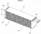
- An integrated module of an evaporator core and a heater core for an automotive air-conditioning system may include evaporator headers 100, evaporator tubes 200, heater headers 300, heater tubes 400, and heat-dissipating fins 500.
- the evaporator headers 100 which are parts for providing circulation paths of a coolant for cooling, are connected to an automotive cooling cycle (not shown), so a coolant at low temperature and low pressure flows into the evaporator headers 100 and is then discharged after exchanging heat with air supplied by a fan.
- the evaporator headers 100 are pipes and arranged to face each other in pairs with a gap therebetween, as shown in FIG. 3 , and a coolant of the cooling cycle flows inside through a first side, moves to a second side through the evaporator tubes 200 to be described below, exchanges heat with air, and is then discharged to the cooling cycle.
- the evaporator headers 100 as shown in FIG. 3 , have entrances 100a for a coolant at a side.
- the evaporator headers 100 may be stacked in a plurality of sets, depending on capacity, and have a separator therein by which the coolant flows to the second side through the separators.
- the evaporator headers 100 may be formed such that the number of tubes 200 through which the coolant flowing inside flows to the second side is gradually increased when the coolant is circulated.
- the evaporator headers 100 may be formed such that a coolant flowing to the first side flows to the second side through two tubes 200, returns to the first side through three tubes 200, and then flows back to the second side through four tubes 200.
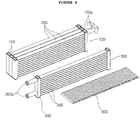
- the evaporator tubes 200 are laterally arranged between the pair of evaporator headers 100 to communicate with the evaporator headers 100, as shown in FIG. 4 , in order that the coolant flows in a zigzag pattern and cools the air supplied by the fan by exchanging heat with the air.
- the number of the evaporator tubes 200 may be changed in accordance with evaporation load, and as shown in FIG. 3 , the top may be covered and protected by a reinforcing plate 150.
- the heater headers 300 which are parts for providing circulation paths of cooling water of an engine for heating, are connected to an engine (not shown), so cooling water heated by the engine flows into the heater headers 300 and is then discharged after exchanging heat with air supplied by a fan
- the heater headers 300 are, as shown in FIG. 3 , similar to the evaporator headers 100, formed in pairs such that the pair makes a set, and cooling water flows inside through a first side, moves to a second side through the heater tubes 400 to be described below, exchanges heat with air, and is then discharged to the cooling cycle.
- the heater headers 300 as shown in FIG. 3 , have entrances 300a for cooling water at a side and have a separator therein to allow cooling water to flow to another side.
- the heater headers 300 may be formed in a single set, or may be stacked in a plurality of sets, depending on the capacity.
- the entrances 300a of the heater headers 300 and the entrances 100a of the evaporator headers 100 may be formed at opposite sides to minimize thermal interference, or may be formed at the same side, depending on the installation environment.
- the heater headers 300 as shown in FIG. 3 , have the same length as the evaporator headers 100 described above, so the heater headers 300 are stacked on the evaporator headers 100 in a single unit, thereby making an integrated module.
- the heater headers 300 are integrated with the evaporator headers 400 and provide individual fluid circulation channels, thereby reducing the volume of existing facilities.
- the heater headers 300 and the evaporator headers 100 may be separately manufactured and then stacked and welded or coupled by fasteners into an integrated unit, or may be may be stacked in an integrated unit.
- the heater tubes 400 are laterally arranged between the pair of heater headers 100 to communicate with the header pipes 100, as show in FIG. 4 , in order that the cooling water flows in a zigzag pattern and heats the air supplied by the fan using the heat of the cooling water by exchanging heat with the air.
- the heat-dissipating fins 500 are disposed among the evaporator tubes 200 and the heater tubes 400 in contact with them and transmit heat of the evaporator tubes 200 or heat of the heater tubes 400 to air.
- the heat-dissipating fins 500 may be continuously formed in the shape of waves, or may be formed in other shapes known in the art, for example, in a zigzag pattern.
- the heat-dissipating fins 500 may extend from the spaces among the evaporator tubes 200 to the spaces among the heater tubes 400, in an integrated unit.
- the heat-dissipating fins 500 are formed in an integrated unit having a length corresponding to the widths of the evaporator header 100 and the heater headers 300 and can extend from the spaces among the evaporator tubes 200 to the spaces among the heater tubes 400. Accordingly, the heat-dissipating fins 500 can increase the contact area with air for transmitting heat from the heater tubes 400 or cold from the evaporator tubes 200 and transmit cold or heat through a larger area, so the performance of cooling/heating of an air conditioner can be improved.
- the integrated module of an evaporator core and a heater core for an automotive air conditioner of the present invention may be formed in a structure in which the evaporator tubes 200 and the heater tubes 400 are horizontally arranged and the evaporator headers 100 and the heater headers 300 are vertically arranged. Further, the integrated module can be formed in a rectangular structure having a width larger than a height.
- the heat exchanger of the present invention can have a large heat transfer area, as compared with the case with the tubes 200 and 400 vertically arranged, as described above with reference to FIGS. 2A and 2B .
- the present invention may further include, as shown in FIG. 6 , a drain guide 700.
- the drain guide 700 is a part for preventing condensate water produced on the surfaces of the evaporator tubes 200 by heat of vaporization of the coolant from being scattered by force from the fan.
- the drain guide 700 is disposed opposite to the fan and is disposed close to the heater headers 300 and the heater tubes 400, as shown in FIGS. 6 and 7 , or disposed close to the evaporator headers 100 and the evaporator tubes 200, unlike the figures. Further, the drain guide 700 provides channels for cold air and prevents condensate water from being discharged with the cold air by collecting and dropping the condensate water discharged with the cold air.
- the drain guide 700 may include guide bodies 710 and baffle boards 720.
- the guide bodies 710 are formed in a plate shape and vertically disposed at sides of the tubes 200 with regular intervals, thereby providing channels, which are the spaces among them, for cold air.
- the guide bodies 710 may be fixed to the reinforcing plate 150 for protecting the tubes 200 and 400 by fixing members (not shown).
- the fixing members for fixing the guide bodies 710 may be brackets or bolts (not shown), and the guide bodies 710 may be coupled in a hook type or a clamp type.
- the guide bodies 710 as shown in FIG. 7 , each have bending portions in a zigzag pattern with inclined surfaces, so they can change the flow direction of cold air in a zigzag pattern.
- the guide bodies 710 may be formed in the shape of a flat plate without the bending portions.
- the baffle boards 720 are parts that block cold air discharged through the channels formed by the guide bodies 710 and collect and drop condensate water in the cold air.
- the baffle boards 720 protrude on both sides of the guide bodies 710 alternately in the spaces among the guide bodies 710, thereby alternately blocking the cold air flowing through the spaces and separating condensate water from the cold air.
- the air supplied from the fan is cooled by exchanging heat with a coolant while passing through the evaporator tubes 200 and the heat-dissipating fins 500, and is discharged with the condensate water produced in the surfaces of the evaporator tubes 200 or the heat-dissipating fins 500 through the spaces among the guide bodies 710.
- the condensate water that is discharged with the cold air is separated from the cold air by hitting against the baffle boards 720 protruding in the spaces, and is then dropped along the baffle boards 720 and discharged to a specific drain.
- baffle boards 720 may protrude at the bending portions of the guide bodies 710 and may protrude at the same angle as the inclined surfaces of the guide bodies 710 at the bending portions.
- water can be collected and dropped by the guide bodies 710 and the baffle boards 720 without scattering even through the tubes 200 are horizontally arranged, so the tubes 200 and 400 can be horizontally arranged. Accordingly, the heat transfer area can be increased, as compared with evaporators having the same size and capacity.
- the drain guide 700 of the present invention may further include a condensate water filter 730.
- the condensate water filter 730 is coupled to the exit ends of thee guide bodies 710 and covers the spaces among the guide bodies 710, that is, the channels for cold air, thereby filtering the condensate water remaining in the cold air.
- the condensate water filter 730 prevents condensate water from scattering by filtering the condensate water that is discharged through the spaces among the guide bodies 710 without being separated by the baffle boards 720.
- the evaporator headers 100 and the heater headers 300 are stacked and fixed in a single unit, it is possible to simplify the automotive air conditioner. Therefore, it is possible to more easily install the heat exchanger and reduce the volume, whereby it is possible to reduce the weight of a vehicle.
Landscapes
- Engineering & Computer Science (AREA)
- Physics & Mathematics (AREA)
- Thermal Sciences (AREA)
- Mechanical Engineering (AREA)
- General Engineering & Computer Science (AREA)
- Chemical & Material Sciences (AREA)
- Geometry (AREA)
- Combustion & Propulsion (AREA)
- Analytical Chemistry (AREA)
- Power Engineering (AREA)
- Air-Conditioning For Vehicles (AREA)
Applications Claiming Priority (1)
| Application Number | Priority Date | Filing Date | Title |
|---|---|---|---|
| KR1020150109561A KR20170016149A (ko) | 2015-08-03 | 2015-08-03 | 자동차 공조장치용 증발기 코어와 히터 코어의 일체형 모듈 |
Publications (1)
| Publication Number | Publication Date |
|---|---|
| EP3138710A1 true EP3138710A1 (fr) | 2017-03-08 |
Family
ID=56567516
Family Applications (1)
| Application Number | Title | Priority Date | Filing Date |
|---|---|---|---|
| EP16182545.0A Withdrawn EP3138710A1 (fr) | 2015-08-03 | 2016-08-03 | Module intégré avec un évaporateur et un dispositif de chauffage pour conditionneur d'air |
Country Status (5)
| Country | Link |
|---|---|
| US (1) | US20170036509A1 (fr) |
| EP (1) | EP3138710A1 (fr) |
| JP (1) | JP2017030742A (fr) |
| KR (1) | KR20170016149A (fr) |
| CN (1) | CN106403385A (fr) |
Cited By (1)
| Publication number | Priority date | Publication date | Assignee | Title |
|---|---|---|---|---|
| GB2558319A (en) * | 2016-12-22 | 2018-07-11 | Tata Motors European Technical Ct Plc | Heat exchange module, method of manufacturing heat exchange modules, vehicle cooling system, vehicle comprising the same, and method of manufacturing vehicle |
Families Citing this family (3)
| Publication number | Priority date | Publication date | Assignee | Title |
|---|---|---|---|---|
| CN108645077A (zh) * | 2018-08-13 | 2018-10-12 | 上海加冷松芝汽车空调股份有限公司 | 一种换热器 |
| US20220024281A1 (en) * | 2018-12-11 | 2022-01-27 | Denso Thermal Systems S.P.A. | Air conditioning system provided with a droplet separator, in particular for a motor vehicle |
| JP6933346B1 (ja) * | 2020-09-04 | 2021-09-08 | 三菱製鋼株式会社 | 空気調和装置 |
Citations (5)
| Publication number | Priority date | Publication date | Assignee | Title |
|---|---|---|---|---|
| US3306071A (en) * | 1965-08-26 | 1967-02-28 | Earl F Holyfield | Cooling coil with condensate director |
| EP0431917A1 (fr) * | 1989-12-07 | 1991-06-12 | Showa Aluminum Kabushiki Kaisha | Duplex échangeur de chaleur |
| FR2785978A1 (fr) * | 1998-11-16 | 2000-05-19 | Valeo Thermique Moteur Sa | Echangeur de chaleur multiple a intercalaires communs |
| US6170565B1 (en) * | 1996-12-04 | 2001-01-09 | Zexel Corporation | Heat exchanger |
| KR20140114191A (ko) | 2013-03-18 | 2014-09-26 | 한라비스테온공조 주식회사 | 차량용 공조 장치 |
Family Cites Families (14)
| Publication number | Priority date | Publication date | Assignee | Title |
|---|---|---|---|---|
| US1896656A (en) * | 1930-09-10 | 1933-02-07 | B F Sturtevant Co | Assembly of metal surfaces |
| US3659402A (en) * | 1970-03-30 | 1972-05-02 | Howard Alliger | Multiple screen construction |
| DE4119216C2 (de) * | 1991-06-11 | 1994-09-22 | Wurz Dieter | Tropfenabscheider |
| JP3687876B2 (ja) * | 1996-12-04 | 2005-08-24 | 株式会社ゼクセルヴァレオクライメートコントロール | 熱交換器 |
| FR2770898B1 (fr) * | 1997-11-10 | 2000-02-25 | Valeo Climatisation | Dispositif de retention de condensats pour evaporateur |
| US6561264B2 (en) * | 2000-03-16 | 2003-05-13 | Denso Corporation | Compound heat exhanger having cooling fins introducing different heat exhanging performances within heat exchanging core portion |
| KR100755376B1 (ko) * | 2000-12-30 | 2007-09-04 | 한라공조주식회사 | 일체형 열교환기 |
| JP2004060957A (ja) * | 2002-07-26 | 2004-02-26 | Sanyo Electric Co Ltd | 熱移動装置 |
| BE1015880A3 (nl) * | 2004-02-03 | 2005-10-04 | Atlas Copco Airpower Nv | Warmtewisselaar. |
| US7618472B2 (en) * | 2005-12-16 | 2009-11-17 | Uop Llc | Vane-type demister |
| JP2007192447A (ja) * | 2006-01-19 | 2007-08-02 | Showa Denko Kk | 蒸発器 |
| US7686862B1 (en) * | 2008-09-22 | 2010-03-30 | Peerless Mfg. Co. | Composite vane and method of manufacture |
| KR20110100002A (ko) * | 2010-03-03 | 2011-09-09 | 안황재 | 상변화 물질을 포함하는 이중 증발기 |
| JP2013113572A (ja) * | 2011-12-01 | 2013-06-10 | Keihin Corp | 熱交換器ユニット |
-
2015
- 2015-08-03 KR KR1020150109561A patent/KR20170016149A/ko active Application Filing
-
2016
- 2016-05-25 CN CN201610353101.6A patent/CN106403385A/zh active Pending
- 2016-08-03 JP JP2016152828A patent/JP2017030742A/ja active Pending
- 2016-08-03 US US15/227,376 patent/US20170036509A1/en not_active Abandoned
- 2016-08-03 EP EP16182545.0A patent/EP3138710A1/fr not_active Withdrawn
Patent Citations (5)
| Publication number | Priority date | Publication date | Assignee | Title |
|---|---|---|---|---|
| US3306071A (en) * | 1965-08-26 | 1967-02-28 | Earl F Holyfield | Cooling coil with condensate director |
| EP0431917A1 (fr) * | 1989-12-07 | 1991-06-12 | Showa Aluminum Kabushiki Kaisha | Duplex échangeur de chaleur |
| US6170565B1 (en) * | 1996-12-04 | 2001-01-09 | Zexel Corporation | Heat exchanger |
| FR2785978A1 (fr) * | 1998-11-16 | 2000-05-19 | Valeo Thermique Moteur Sa | Echangeur de chaleur multiple a intercalaires communs |
| KR20140114191A (ko) | 2013-03-18 | 2014-09-26 | 한라비스테온공조 주식회사 | 차량용 공조 장치 |
Cited By (1)
| Publication number | Priority date | Publication date | Assignee | Title |
|---|---|---|---|---|
| GB2558319A (en) * | 2016-12-22 | 2018-07-11 | Tata Motors European Technical Ct Plc | Heat exchange module, method of manufacturing heat exchange modules, vehicle cooling system, vehicle comprising the same, and method of manufacturing vehicle |
Also Published As
| Publication number | Publication date |
|---|---|
| US20170036509A1 (en) | 2017-02-09 |
| KR20170016149A (ko) | 2017-02-13 |
| JP2017030742A (ja) | 2017-02-09 |
| CN106403385A (zh) | 2017-02-15 |
Similar Documents
| Publication | Publication Date | Title |
|---|---|---|
| US20170038104A1 (en) | Evaporator having vertical arrangement of header pipe for vehicle air conditioner | |
| EP2171385B1 (fr) | Système de refroidissement auxiliaire | |
| EP3138710A1 (fr) | Module intégré avec un évaporateur et un dispositif de chauffage pour conditionneur d'air | |
| EP3008416B1 (fr) | Échangeur thermique destiné à un véhicule | |
| US9671128B2 (en) | Air conditioner having angled heat exchangers | |
| CN104995474B (zh) | 用于空气调节回路的具有制冷剂供给部的冷凝器 | |
| CN111928678A (zh) | 用于风冷式冷却器的热交换器 | |
| EP1998133A1 (fr) | Echangeur de chaleur et echangeur de chaleur de type integre | |
| KR100687637B1 (ko) | 열교환기 | |
| EP3137836B1 (fr) | Échangeur de chaleur amélioré | |
| EP2724107B1 (fr) | Échangeur de chaleur à enveloppe et à tubes avec microcanaux | |
| CN207702700U (zh) | 一种散热装置 | |
| KR20170041674A (ko) | 자동차 공조장치용 증발기 코어와 히터 코어의 일체형 모듈 | |
| KR102609386B1 (ko) | 열교환기 및 이를 포함하는 차량용 공조장치 | |
| US9834061B2 (en) | Assembly including a heat exchanger and a mounting on which said exchanger is mounted | |
| KR102078367B1 (ko) | 공기조화기 | |
| JP2006266114A (ja) | 熱交換装置 | |
| CN107806723B (zh) | 壳管式冷凝器 | |
| EP4198440A1 (fr) | Échangeur de chaleur | |
| EP4050292A1 (fr) | Échangeur de chaleur | |
| JP3861787B2 (ja) | 複合熱交換器及びこれを備える自動車 | |
| US20140182326A1 (en) | Heat Exchanger For A Heating, Ventilation And/Or Air-Conditioning Unit | |
| CN114894010A (zh) | 换热器 | |
| JP2024519392A (ja) | 複合熱交換器 | |
| KR20050019509A (ko) | 공기조화장치용 히터 |
Legal Events
| Date | Code | Title | Description |
|---|---|---|---|
| PUAI | Public reference made under article 153(3) epc to a published international application that has entered the european phase |
Free format text: ORIGINAL CODE: 0009012 |
|
| 17P | Request for examination filed |
Effective date: 20160803 |
|
| AK | Designated contracting states |
Kind code of ref document: A1 Designated state(s): AL AT BE BG CH CY CZ DE DK EE ES FI FR GB GR HR HU IE IS IT LI LT LU LV MC MK MT NL NO PL PT RO RS SE SI SK SM TR |
|
| AX | Request for extension of the european patent |
Extension state: BA ME |
|
| RBV | Designated contracting states (corrected) |
Designated state(s): AL AT BE BG CH CY CZ DE DK EE ES FI FR GB GR HR HU IE IS IT LI LT LU LV MC MK MT NL NO PL PT RO RS SE SI SK SM TR |
|
| 17Q | First examination report despatched |
Effective date: 20171122 |
|
| STAA | Information on the status of an ep patent application or granted ep patent |
Free format text: STATUS: THE APPLICATION IS DEEMED TO BE WITHDRAWN |
|
| 18D | Application deemed to be withdrawn |
Effective date: 20180404 |