EP3138530A2 - Scananordnung mit scankopf - Google Patents
Scananordnung mit scankopf Download PDFInfo
- Publication number
- EP3138530A2 EP3138530A2 EP16154692.4A EP16154692A EP3138530A2 EP 3138530 A2 EP3138530 A2 EP 3138530A2 EP 16154692 A EP16154692 A EP 16154692A EP 3138530 A2 EP3138530 A2 EP 3138530A2
- Authority
- EP
- European Patent Office
- Prior art keywords
- scan
- frame
- arrangement according
- scanning
- membrane
- Prior art date
- Legal status (The legal status is an assumption and is not a legal conclusion. Google has not performed a legal analysis and makes no representation as to the accuracy of the status listed.)
- Granted
Links
Images
Classifications
-
- A—HUMAN NECESSITIES
- A61—MEDICAL OR VETERINARY SCIENCE; HYGIENE
- A61B—DIAGNOSIS; SURGERY; IDENTIFICATION
- A61B1/00—Instruments for performing medical examinations of the interior of cavities or tubes of the body by visual or photographical inspection, e.g. endoscopes; Illuminating arrangements therefor
- A61B1/24—Instruments for performing medical examinations of the interior of cavities or tubes of the body by visual or photographical inspection, e.g. endoscopes; Illuminating arrangements therefor for the mouth, i.e. stomatoscopes, e.g. with tongue depressors; Instruments for opening or keeping open the mouth
-
- A—HUMAN NECESSITIES
- A61—MEDICAL OR VETERINARY SCIENCE; HYGIENE
- A61B—DIAGNOSIS; SURGERY; IDENTIFICATION
- A61B5/00—Measuring for diagnostic purposes; Identification of persons
- A61B5/68—Arrangements of detecting, measuring or recording means, e.g. sensors, in relation to patient
- A61B5/6801—Arrangements of detecting, measuring or recording means, e.g. sensors, in relation to patient specially adapted to be attached to or worn on the body surface
- A61B5/6813—Specially adapted to be attached to a specific body part
- A61B5/6814—Head
- A61B5/682—Mouth, e.g., oral cavity; tongue; Lips; Teeth
-
- A—HUMAN NECESSITIES
- A61—MEDICAL OR VETERINARY SCIENCE; HYGIENE
- A61B—DIAGNOSIS; SURGERY; IDENTIFICATION
- A61B1/00—Instruments for performing medical examinations of the interior of cavities or tubes of the body by visual or photographical inspection, e.g. endoscopes; Illuminating arrangements therefor
- A61B1/00163—Optical arrangements
- A61B1/00172—Optical arrangements with means for scanning
-
- A—HUMAN NECESSITIES
- A61—MEDICAL OR VETERINARY SCIENCE; HYGIENE
- A61B—DIAGNOSIS; SURGERY; IDENTIFICATION
- A61B5/00—Measuring for diagnostic purposes; Identification of persons
- A61B5/0059—Measuring for diagnostic purposes; Identification of persons using light, e.g. diagnosis by transillumination, diascopy, fluorescence
- A61B5/0062—Arrangements for scanning
-
- A—HUMAN NECESSITIES
- A61—MEDICAL OR VETERINARY SCIENCE; HYGIENE
- A61B—DIAGNOSIS; SURGERY; IDENTIFICATION
- A61B5/00—Measuring for diagnostic purposes; Identification of persons
- A61B5/0059—Measuring for diagnostic purposes; Identification of persons using light, e.g. diagnosis by transillumination, diascopy, fluorescence
- A61B5/0082—Measuring for diagnostic purposes; Identification of persons using light, e.g. diagnosis by transillumination, diascopy, fluorescence adapted for particular medical purposes
- A61B5/0084—Measuring for diagnostic purposes; Identification of persons using light, e.g. diagnosis by transillumination, diascopy, fluorescence adapted for particular medical purposes for introduction into the body, e.g. by catheters
-
- A—HUMAN NECESSITIES
- A61—MEDICAL OR VETERINARY SCIENCE; HYGIENE
- A61B—DIAGNOSIS; SURGERY; IDENTIFICATION
- A61B5/00—Measuring for diagnostic purposes; Identification of persons
- A61B5/103—Measuring devices for testing the shape, pattern, colour, size or movement of the body or parts thereof, for diagnostic purposes
- A61B5/107—Measuring physical dimensions, e.g. size of the entire body or parts thereof
- A61B5/1076—Measuring physical dimensions, e.g. size of the entire body or parts thereof for measuring dimensions inside body cavities, e.g. using catheters
-
- A—HUMAN NECESSITIES
- A61—MEDICAL OR VETERINARY SCIENCE; HYGIENE
- A61B—DIAGNOSIS; SURGERY; IDENTIFICATION
- A61B5/00—Measuring for diagnostic purposes; Identification of persons
- A61B5/103—Measuring devices for testing the shape, pattern, colour, size or movement of the body or parts thereof, for diagnostic purposes
- A61B5/107—Measuring physical dimensions, e.g. size of the entire body or parts thereof
- A61B5/1077—Measuring of profiles
-
- A—HUMAN NECESSITIES
- A61—MEDICAL OR VETERINARY SCIENCE; HYGIENE
- A61B—DIAGNOSIS; SURGERY; IDENTIFICATION
- A61B5/00—Measuring for diagnostic purposes; Identification of persons
- A61B5/103—Measuring devices for testing the shape, pattern, colour, size or movement of the body or parts thereof, for diagnostic purposes
- A61B5/107—Measuring physical dimensions, e.g. size of the entire body or parts thereof
- A61B5/1079—Measuring physical dimensions, e.g. size of the entire body or parts thereof using optical or photographic means
-
- G—PHYSICS
- G06—COMPUTING OR CALCULATING; COUNTING
- G06T—IMAGE DATA PROCESSING OR GENERATION, IN GENERAL
- G06T7/00—Image analysis
- G06T7/0002—Inspection of images, e.g. flaw detection
- G06T7/0012—Biomedical image inspection
-
- G—PHYSICS
- G06—COMPUTING OR CALCULATING; COUNTING
- G06T—IMAGE DATA PROCESSING OR GENERATION, IN GENERAL
- G06T7/00—Image analysis
- G06T7/50—Depth or shape recovery
- G06T7/521—Depth or shape recovery from laser ranging, e.g. using interferometry; from the projection of structured light
-
- G—PHYSICS
- G06—COMPUTING OR CALCULATING; COUNTING
- G06T—IMAGE DATA PROCESSING OR GENERATION, IN GENERAL
- G06T7/00—Image analysis
- G06T7/70—Determining position or orientation of objects or cameras
- G06T7/73—Determining position or orientation of objects or cameras using feature-based methods
- G06T7/74—Determining position or orientation of objects or cameras using feature-based methods involving reference images or patches
-
- H—ELECTRICITY
- H04—ELECTRIC COMMUNICATION TECHNIQUE
- H04N—PICTORIAL COMMUNICATION, e.g. TELEVISION
- H04N13/00—Stereoscopic video systems; Multi-view video systems; Details thereof
- H04N13/20—Image signal generators
- H04N13/204—Image signal generators using stereoscopic image cameras
- H04N13/207—Image signal generators using stereoscopic image cameras using a single 2D image sensor
- H04N13/221—Image signal generators using stereoscopic image cameras using a single 2D image sensor using the relative movement between cameras and objects
-
- A—HUMAN NECESSITIES
- A61—MEDICAL OR VETERINARY SCIENCE; HYGIENE
- A61C—DENTISTRY; APPARATUS OR METHODS FOR ORAL OR DENTAL HYGIENE
- A61C9/00—Impression cups, i.e. impression trays; Impression methods
- A61C9/004—Means or methods for taking digitized impressions
- A61C9/0046—Data acquisition means or methods
- A61C9/0053—Optical means or methods, e.g. scanning the teeth by a laser or light beam
-
- G—PHYSICS
- G06—COMPUTING OR CALCULATING; COUNTING
- G06T—IMAGE DATA PROCESSING OR GENERATION, IN GENERAL
- G06T2207/00—Indexing scheme for image analysis or image enhancement
- G06T2207/10—Image acquisition modality
- G06T2207/10004—Still image; Photographic image
- G06T2207/10012—Stereo images
-
- G—PHYSICS
- G06—COMPUTING OR CALCULATING; COUNTING
- G06T—IMAGE DATA PROCESSING OR GENERATION, IN GENERAL
- G06T2207/00—Indexing scheme for image analysis or image enhancement
- G06T2207/30—Subject of image; Context of image processing
- G06T2207/30004—Biomedical image processing
Definitions
- the invention relates to a scanning arrangement, according to the preamble of claims 1 and 14, and to a method for scanning a scanning area, according to the preamble of claim 13.
- the invention is therefore based on the object to provide a scanning arrangement according to the preamble of claim 1 and 14 and a method for scanning a scan area according to the preamble of claim 13, which are significantly improved in terms of the scan result without significant capital expenditure.
- the film-like or flat, elastically extensible material is applied to the scanning area. This can be done by mechanical means as appropriate configured frame elements be realized, or for example by adhesion between the scan area and the material.
- the material - or at least one frame element in a modified embodiment - a pattern that is particularly easy to scan.
- the good scannability results in a considerable advance in the area with an immediate scanning of the scan area, which is often low-contrast and usually unpatterned.
- the material which may be like a membrane, for example, or else net-like and which bears tightly against the scanning area, has the same thickness everywhere. This may be, for example, 50 .mu.m or even 100 .mu.m . Surprisingly, the accuracy of detection is not affected by the applied thickness of the material in any way; much more is it significantly higher than a direct scan of the scan area.
- the invention is also particularly suitable for combining captured images of the scan head via a three-dimensional juxtaposition, the so-called "stitching".
- the pattern can be selected in any suitable manner in order to enable a clear localization.
- the preloaded solution has the advantage that no wrinkles can occur, or any existing wrinkles are virtually automatically pulled away.
- the design of the pattern on the material can be adapted to the requirements in a wide range.
- a structure may be provided with elements that are very fine and close to the resolution of the scan head.
- Particularly favorable is the combination of pattern elements that are regular and pattern elements that are irregular.
- the pattern may be applied or formed on the side facing the scanning head, or else on the side facing the scanning region, in which case it is understood that the material is then transparent to the scanning radiation.
- the scanning device with frame elements which extend laterally next to or also on the scanning region and follow it.
- the elongate frame member may extend or extend on the vestibular and / or lingual of the edentulous ridge.
- the frame element then has, as viewed in the horizontal direction, a height profile that corresponds to the occlusal surface of the alveolar ridge, which in this embodiment forms the scanning region.
- frame elements of the frame extend along the scan area, in particular closely adjacent thereto. They have a height profile which corresponds to the height profile of the scan area, the frame elements having at least one two-dimensional or three-dimensional pattern. This pattern can also be provided in addition to the pattern on the material to improve the scan result.
- the frame member may be selected in any suitable manner. Preferably, it is very good plastically deformable.
- a soft metal such as tin or an alloy with tin may be used as the core of the frame member. This may be wrapped with a protective cover which prevents contact with the metallic core of the frame member.
- Another possibility is the realization of the frame element with a sheet that is particularly ductile and can be deformed well.
- the sheet thus provided then preferably extends distally-mesially in its main direction and with a width of a few millimeters in the lingual-vestibular direction. In this way, the sheet metal can be adjusted as accurately as possible to the height profile of the scanning area and bent accordingly.
- Another possibility is the realization of the core of the frame member made of a plastically deformable organic material, such as bitumen, which is in turn coated with a protective coating.
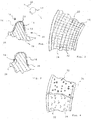
- a scanning assembly 10 includes a scan head 12, and a scan area 14 to be scanned by the scan head 12.
- the scanning region 14 is covered by a material 16, which forms a membrane 18 in the exemplary embodiment shown.
- the scan area 14 is part of a larger structure that extends in three dimensions. Overall, the structure can form a cavity which at least partially surrounds the scan head 12.
- the in Fig. 1 shown scanning region 14 is partially covered by the material 16 in the illustrated embodiment.
- the scan head 12 can be moved along the arrows 20, but also in any other three-dimensional direction, for example perpendicular to the plane of the drawing.
- the scan head 12 is directed onto the scan area 14 and thus onto the material 16 and detects its structure 22.
- the material 16 is bulged toward the scanning head 12. This is due to the corresponding shape of the scan area 14.
- the material 16 abuts the scanning region 14. In the illustrated embodiment, it is held taut between two frame members 26 and 28 of a frame 30 so that it fits snugly against the scan area 14.
- the material 16 can cover the entire scanning area, ie the area to be scanned. But it is also possible to move the material 16 along the scan area 14. This is also Fig. 2 visible; from the comparison of Figures 1 and 2 It follows that the extension of the material 16 is the same length, however, the frame member 26 according to Fig. 2 is arranged higher than the frame member 28 in this figure.
- the material 16 is formed in the illustrated embodiment as a thin membrane.
- the wall thickness of the membrane is, for example, 200 ⁇ m . Due to the tension between the frame elements 26 and 28, the wall thickness is further reduced, for example to 150 ⁇ m .
- the structure 22 of the membrane 18 is selected so that it is particularly visible from the scan head 12.
- An example of such a structure 22 is made Fig. 3 seen.
- the structure consists of a multiplicity of pattern elements 32, 34, which are regularly spaced apart from one another, but preferably also from pattern elements which are arranged irregularly relative to one another ( Fig. 4 ).
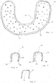
- Fig. 5 a modified version of the membrane 18 can be seen.
- the local frame 30 is circumferentially formed and biases the membrane 18.
- the frame 30 and thus the membrane 30 is three-dimensionally deformable.
- the shape of the frame forms according to Fig. 5 a U, and according to the FIGS. 6 to 8 is the frame 30 so deformable that in the side view in section also a U can be realized.
- One application would be, for example, scanning an already created prosthesis to detect its surface, or scanning a jaw in a patient's mouth.
- film hinges 40 and 42 may be provided between the base leg and the side legs of the U. These can be easily realized by diluting the material of which the frame 30 is made.
- a film hinge 40 is provided, which extends in the middle - approximately in the base of the U - and ensures the desired preformability, while the film hinge 40 adjacent areas of the frame 30 are thin and therefore flexible.
- any other structure with other pattern elements 32, 34 can be realized. It is also possible to adapt the reflection or absorption maximum of the pattern elements 32 and 34 to the detected wavelength range of the scan head 12. Further, instead of the frame 30, a releasable adhesive may be used which holds the membrane 18 on the scan area 14. This can also be done without further ado.
- a network or a structure having other recesses and having pattern elements can also be used in a modified embodiment. These can also be held adjacent to the scan area 14 via a frame 30, via an adhesive or via adhesion, depending on the application.
Landscapes
- Health & Medical Sciences (AREA)
- Life Sciences & Earth Sciences (AREA)
- Engineering & Computer Science (AREA)
- Physics & Mathematics (AREA)
- Surgery (AREA)
- General Health & Medical Sciences (AREA)
- Veterinary Medicine (AREA)
- Public Health (AREA)
- Animal Behavior & Ethology (AREA)
- Medical Informatics (AREA)
- Biophysics (AREA)
- Biomedical Technology (AREA)
- Heart & Thoracic Surgery (AREA)
- Pathology (AREA)
- Molecular Biology (AREA)
- Oral & Maxillofacial Surgery (AREA)
- Dentistry (AREA)
- Radiology & Medical Imaging (AREA)
- Nuclear Medicine, Radiotherapy & Molecular Imaging (AREA)
- Optics & Photonics (AREA)
- Theoretical Computer Science (AREA)
- Computer Vision & Pattern Recognition (AREA)
- General Physics & Mathematics (AREA)
- Epidemiology (AREA)
- Signal Processing (AREA)
- Quality & Reliability (AREA)
- Multimedia (AREA)
- Dental Tools And Instruments Or Auxiliary Dental Instruments (AREA)
- Endoscopes (AREA)
- Ultra Sonic Daignosis Equipment (AREA)
- Apparatus For Radiation Diagnosis (AREA)
- Toys (AREA)
- Length Measuring Devices By Optical Means (AREA)
- Ink Jet (AREA)
- Facsimile Scanning Arrangements (AREA)
- Media Introduction/Drainage Providing Device (AREA)
- Instruments For Viewing The Inside Of Hollow Bodies (AREA)
- Microscoopes, Condenser (AREA)
- Studio Devices (AREA)
- Analysing Materials By The Use Of Radiation (AREA)
Abstract
Description
- Die Erfindung betrifft eine Scananordnung, gemäß dem Oberbegriff von Anspruch 1 sowie 14, sowie ein Verfahren zum Scannen eines Scanbereichs, gemäß dem Oberbegriff von Anspruch 13.
- Für das Scannen des Mundinnenraums - oder auch für das Scannen von Mundinnenraumabformungen, also Modellen oder Abdruckmassen, die die Form des Mundinnenraums wiedergeben - ist es bekannt, im Mundinnenraum oder auf dem Modell Referenzpunkte anzubringen. Diese sollen der Orientierung dienen, aber auch die Qualität des sogenannten "Stitching" verbessern, anhand dessen verschiedene Aufnahmebereiche zur Bereitstellung eines dreidimensionalen Gesamtbildes zueinander ausgerichtet werden.
- Auch wenn bereits beträchtliche Fortschritte bei den Scanergebnissen zu verzeichnen sind, bestehen nach wie vor gewisse Probleme. So muss der Scankopf dreidimensional geführt werden, was entsprechende Fehlereinflüsse hinsichtlich der Präzision induziert. Auch ist der Kontrast der Scanbereiche, die erfasst werden sollen, recht unterschiedlich. Zur Erfassung kleinerer Erhebungen und Vertiefungen ist vorgeschlagen worden, mit einem schrägen Lichteinfall und der entsprechenden Schattenwirkung zu arbeiten.
- Zur Eliminierung von Erkennungsfehlern muss dann aber auch mit Gegenlicht gearbeitet werden, also Lichteinfall aus der Gegenrichtung. Schräger Lichteinfall bedingt jedoch je nach Anordnung des Scanbereiches auch Abdeckungen.
- Um diese Nachteile zu verhindern, ist es auch bekannt geworden, mindestens zwei Scanner im Abstand voneinander anzuordnen und auf den gleichen Scanbereich zu richten und so das Höhenprofil stereometrisch zu erfassen. Dies führt jedoch zu erheblichen Kostennachteilen und auch gegebenenfalls räumlichen Problemen gerade in beengten Hohlräumen dem Mundraum.
- In der europäischen Patentanmeldung
15 180 555.3 - Demgegenüber wäre es jedoch wünschenswert, eine noch flexiblere Lösung zur Verfügung zu stellen.
- Um kompliziert geformte Hohlräume scannen zu können, hat man die Scanstrahlung und deren Zuleitung durch den Scankopf zu verbessern versucht. So ist es bereits vorgeschlagen worden, mit unterschiedlichen Frequenzbereichen der elektromagnetischen Strahlungen zu arbeiten. Bei einer feuchten Oberfläche kann es beispielsweise günstig sein, sichtbares Licht oder UV-Licht zu verwenden. Hingegen sind die Reflekionseigenschaften bestimmter Materialien, aus denen der Hohlraum bestehen kann, einerseits bei Ultraschallstrahlung, andererseits aber bei Röntgenstrahlungen besser.
- Nachteilig hierbei ist es, dass Scanner mit unterschiedlichen Frequenzbereichen bereitgestellt werden müssen, was die Lösung insgesamt verteuert und teilweise auch unpraktikabel macht.
- Daher liegt der Erfindung die Aufgabe zu Grunde, eine Scananordnung gemäß dem Oberbegriff von Anspruch 1 sowie 14 sowie ein Verfahren zum Scannen eines Scanbereichs gemäß dem Oberbegriff von Anspruch 13 zu schaffen, die hinsichtlich des Scanergebnisses ohne nennenswerten Investitionsaufwand deutlich verbessert sind.
- Diese Aufgabe wird erfindungsgemäß durch Anspruch 1, 13 bzw. 14 gelöst. Vorteilhafte Weiterbildungen ergeben sich aus den Unteransprüchen.
- Besonders günstig ist es, dass sich das folienartige oder flächige, elastisch dehnbare Material an den Scanbereich anlegt. Dies kann durch mechanische Mittel wie geeignet ausgestaltete Rahmenelemente realisiert sein, oder beispielsweise durch Adhäsion zwischen dem Scanbereich und dem Material.
- Erfindungsgemäß trägt das Material - oder in modifizierter Ausgestaltung mindestens ein Rahmenelement - ein Muster, das besonders gut scanbar ist. Durch die gute Scanbarkeit ergibt sich ein erheblicher Fortschritt im Bereich mit einem unmittelbaren Scannen des Scanbereichs, der häufig kontrastschwach und in aller Regel ungemustert ist.
- Besonders günstig ist es in diesem Zusammenhang, wenn sich das Material zum Scankopf hin vorgewölbt erstreckt. Hierdurch lassen sich besonders gut Konturen des entsprechend vorgewölbten Scanbereichs erfassen, und zwar auch dann, wenn der Scanbereich selbst einfarbig und unstrukturiert ist.
- Besonders günstig ist es, wenn das Material, das beispielsweise nach der Art einer Membran folienartig oder aber auch netzartig sein kann und eng an dem Scanbereich anliegt, überall die gleiche Dicke aufweist. Diese kann beispielsweise 50 µm oder auch 100 µm betragen. Überraschend wird die Genauigkeit der Erfassung durch die auftragende Dicke des Materials in keiner Weise beeinträchtigt; viel mehr ist sie signifikant höher als bei einem direkten Scan des Scanbereichs.
- Die Erfindung ist auch besonders geeignet, erfasste Bilder des Scankopfes über eine dreidimensionale Aneinanderreihung, das sogenannte "Stitching" miteinander zu verbinden. Hierbei lässt sich erfindungsgemäß das Muster in beliebiger geeigneter Weise auswählen, um eine eindeutige örtliche Lokalisierung zu ermöglichen.
- Während ein Spannen des Materials zwischen Rahmenelementen, gegebenenfalls gepaart mit oder abgelöst durch Adhäsion, bevorzugt ist, ist es in modifizierter Ausgestaltung der Erfindung vorgesehen, das Material über einen lösbaren Kleber an dem Scanbereich zu fixieren. Diese Lösung hat den Vorteil, dass auch bei Erschütterungen und Bewegungen keine Relativbewegung zwischen dem Scanbereich und dem Material stattfindet.
- Demgegenüber hat die vorgespannte Lösung den Vorteil, dass keine Falten entstehen können, bzw. etwaige bestehende Falten gleichsam automatisch weggezogen werden.
- Es versteht sich, dass die Ausgestaltung des Musters auf dem Material in weiten Bereichen an die Erfordernisse anpassbar ist. So kann eine Struktur mit Elementen vorgesehen sein, die sehr fein ist und der Auflösung des Scankopf nahe kommt. Besonders günstig ist die Kombination von Musterelementen, die regelmäßig sind, und Musterelementen, die unregelmäßig sind.
- Das Muster kann auf der dem Scankopf zugewandten Seite angebracht oder ausgebildet sein, oder aber auch auf der dem Scanbereich zugewandten Seite, wobei es sich in diesem Falle versteht, dass das Material dann für die Scanstrahlung transparent ist.
- In einer weiteren bevorzugten Ausgestaltung der Erfindung ist es vorgesehen, die Scanvorrichtung mit Rahmenelementen zu versehen, die sich seitlich neben oder auch auf dem Scanbereich erstrecken und diesem folgen. Wenn der Scanbereich beispielsweise ein Kieferkamm ist, kann das längliche Rahmenelement sich vestibulär und/oder lingual des unbezahnten Kieferkamms erstrecken, oder auf diesem verlaufen. Das Rahmenelement hat dann - in der horizontalen Richtung betrachtet - einen Höhenverlauf, der der okklusalen Fläche des Kieferkamms entspricht, die in dieser Ausführungsform den Scanbereich bildet.
- Günstigerweise ist es vorgesehen, dass sich Rahmenelemente des Rahmens entlang des Scanbereichs erstrecken, insbesondere diesem eng benachbart. Sie weisen einen Höhenverlauf auf, der dem Höhenverlauf des Scanbereichs entspricht, wobei die Rahmenelemente mindestens ein zweidimensionales oder dreidimensionales Muster aufweisen. Dieses Muster kann zur Verbesserung des Scanergebnisses auch zusätzlich zum Muster auf dem Material vorgesehen sein.
- Eine entsprechende Realisierung ist auch bei einer unbezahnten Prothese möglich.
- Das Rahmenelement kann in beliebiger geeigneter Weise ausgewählt werden. Bevorzugt ist es sehr gut plastisch verformbar. Beispielsweise kann ein weiches Metall wie Zinn oder eine Legierung mit Zinn als Kern des Rahmenelements verwendet werden. Diese kann mit einem Schutzüberzug umhüllt sein, der eine Berührung mit dem metallischen Kern des Rahmenelements unterbindet.
- Eine weitere Möglichkeit ist die Realisierung des Rahmenelements mit einem Blech, das besonders duktil ist und sich gut verformen lässt.
- Das so vorgesehen Blech erstreckt sich dann bevorzugt distal-mesial in seiner Hauptrichtung und mit einer Breite von wenigen Millimetern in lingual-vestibulärer Richtung. Auf diese Weise lässt sich das Blech möglichst genau dem Höhenverlauf des Scanbereichs anpassen und entsprechend verbiegen.
- Es kann kurzerhand auf den Scanbereich aufgedrückt und dann gescannt werden.
- Auch in diesem Fall ist die Realisierung eines Schutzüberzugs möglich, der die plastische Biegbarkeit des Blechs jedoch nicht beeinträchtigen sollte.
- Eine weitere Möglichkeit ist die Realisierung des Kerns des Rahmenelements aus einem plastisch verformbaren organischen Material, beispielsweise aus Bitumen, das widerum mit einem Schutzüberzug umhüllt ist.
- Weitere Vorteile, Einzelheiten und Merkmale ergeben sich aus der nachfolgenden Beschreibung mehrerer Ausführungsbeispiele der Erfindung anhand der Zeichnung:
- Es zeigen:
- Fig. 1
- eine schematische Anordnung einer Scanvorrichtung in teilweiser Schnittansicht;
- Fig. 2
- die Anordnung gemäß
Fig. 1 , jedoch mit einem anders angeordneten Material; - Fig. 3
- die Ausführungsform der Scanvorrichtung gemäß
Fig. 1 und Fig. 2 , mit einem beispielhaften Muster; - Fig. 4
- eine weitere Ausführungsform des Materials;
- Fig. 5
- eine weitere Ausführungsform des Materials, das von Rahmenelementen eines Rahmens gespannt gehalten ist;
- Fig. 6
- eine Schnittansicht einer weiteren Ausführungsform des Rahmens gemäß
Fig. 5 ; - Fig. 7
- eine Schnittansicht einer weiteren Ausführungsform des Rahmens gemäß
Fig. 6 ; und - Fig. 8
- eine Schnittansicht einer weiteren Ausführungsform des Rahmens gemäß
Fig. 7 . - Wie aus
Fig. 1 schematisch ersichtlich ist, ist es bei der dargestellten Ausführungsform vorgesehen, dass eine Scananordnung 10 einen Scankopf 12 umfasst, sowie einen Scanbereich 14, der vom Scankopf 12 gescannt werden soll. - Erfindungsgemäß ist der Scanbereich 14 von einem Material 16 abgedeckt, das in dem dargestellten Ausführungsbeispiel eine Membran 18 bildet.
- Der Scanbereich 14 ist Teil einer größeren Struktur, die sich dreidimensional erstreckt. Insgesamt kann die Struktur einen Hohlraum bilden, der den Scankopf 12 mindestens teilweise umgibt.
- Der in
Fig. 1 dargestellte Scanbereich 14 ist in dem dargestellten Ausführungsbeispiel teilweise von dem Material 16 abgedeckt. Für das Scannen kann der Scankopf 12 entlang der Pfeile 20 bewegt werden, aber auch in einer beliebigen anderen dreidimensionalen Richtung, beispielsweise senkrecht zur Zeichnungsebene. Der Scankopf 12 ist auf den Scanbereich 14 und damit auf das Material 16 gerichtet und erfasst dessen Struktur 22. - Wie aus
Fig. 1 ersichtlich ist, ist das Material 16 zum Scankopf 12 hin vorgewölbt. Dies liegt in der entsprechenden Form des Scanbereich 14 begründet. Das Material 16 liegt an dem Scanbereich 14 an. Im dargestellten Ausführungsbeispiel ist es zwischen zwei Rahmenelementen 26 und 28 eines Rahmens 30 gespannt gehalten, so dass es eng an dem Scanbereich 14 anliegt. - In dem Zustand gemäß
Fig. 1 sind die Rahmenelemente 26 und 28 etwa auf gleicher Höhe. - Das Material 16 kann den gesamten Scanbereich abdecken, also den Bereich, der gescannt werden soll. Es ist aber auch möglich, das Material 16 entlang des Scanbereichs 14 zu verschieben. Dies ist auch
Fig. 2 ersichtlich; aus dem Vergleich derFiguren 1 und 2 ergibt sich, dass die Erstreckung des Materials 16 gleich lang ist, jedoch das Rahmenelement 26 gemäßFig. 2 höher angeordnet ist als das Rahmenelement 28 in dieser Figur. - Das Material 16 ist in dem dargestellten Ausführungsbeispiel als dünne Membran ausgebildet. Die Wandstärke der Membran beträgt beispielsweise 200 µm. Durch die Spannung zwischen den Rahmenelementen 26 und 28 ist die Wandstärke weiter reduziert, beispielsweise auf 150 µm.
- Die Struktur 22 der Membran 18 ist so ausgewählt, dass sie von dem Scankopf 12 besonders gut erkennbar ist. Ein Beispiel für eine derartige Struktur 22 ist aus
Fig. 3 ersichtlich. Die Struktur besteht aus einer Vielzahl von Musterelementen 32, 34, die voneinander regelmäßig beabstandet sind, aber bevorzugt auch aus Musterelementen, die unregelmäßig zueinander angeordnet sind (Fig. 4 ). - Durch die Verformung der Membran 18 ergibt sich eine entsprechend der Dehnung der Membran geänderte Anordnung der Musterelemente 34 und 32 zueinander, aus welcher sich die Form des Scanbereichs 14 bestimmen lässt.
- Besonders günstig lässt sich dies realisieren, wenn regelmäßig zueinander angeordnete und unregelmäßig zueinander angeordnete Musterelemente 32 und 34 miteinander kombiniert sind. Ein Beispiel für derartige unregelmäßig angeordnete Musterelemente ist aus
Fig. 4 ersichtlich. - Aus
Fig. 5 ist eine modifizierte Version der Membran 18 ersichtlich. Bei dieser Version ist der dortige Rahmen 30 umlaufend ausgebildet und spannt die Membran 18 auf. - Der Rahmen 30 und damit die Membran 30 ist dreidimensional verformbar. In der Draufsicht bildet die Form des Rahmens gemäß
Fig. 5 ein U, und gemäß denFiguren 6 bis 8 ist der Rahmen 30 so verformbar, dass in der Seitenansicht im Schnitt sich ebenfalls ein U realisieren lässt. - Eine Anwendung wäre beispielsweise das Scannen einer bereits erzeugten Prothese, um deren Oberfläche festzustellen, oder aber das Scannen eines Kiefers im Mund eines Patienten.
- Um die Spannung in der Membran aufrecht zu erhalten und zu erreichen, dass auch kleinste Unebenheiten des Scanbereichs erfasst werden, ist es vorgesehen, die in
Fig. 6 dargestellte Anordnung aus dem Rahmen 30 und der nicht ersichtlichen und in dem Rahmen gespannten Membran 18 anzudrücken oder in beliebiger anderer Weise dafür zu sorgen, dass der Kontakt zwischen dem Scanbereich und der Membran 18 sicher aufrechterhalten bleibt. - Um das erwünschte doppelte Abkippen des Rahmens 30 sicherzustellen, kann gemäß
Fig. 6 die Realisierung von Filmscharnieren 40 und 42 zwischen dem Basisschenkel und den Seitenschenkeln des U vorgesehen sein. Diese lassen sich durch Verdünnung des Materials, aus dem der Rahmen 30 besteht, leicht realisieren. - Gemäß
Fig. 8 ist lediglich ein Filmscharnier 40 vorgesehen, das sich mittig - etwa in der Basis des U - erstreckt und die erwünschte Vorformbarkeit gewährleistet, während die dem Filmscharnier 40 benachbarten Bereiche des Rahmens 30 dünn ausgebildet sind und daher flexibel sind. - Es versteht sich, dass die Erfindung nicht auf die dargestellten Ausgestaltungen beschränkt ist. Beispielsweise kann anstelle der Struktur 22 eine beliebige andere Struktur mit anderen Musterelementen 32, 34 realisiert sein. Es ist auch möglich, das Reflektions- bzw. Absorbtionsmaximum der Musterelemente 32 und 34 an den erfassten Wellenlängenbereich des Scankopfs 12 anzupassen. Ferner kann anstelle des Rahmens 30 ein lösbarer Kleber verwendet werden, der die Membran 18 auf dem Scanbereich 14 hält. Dies kann auch kurzerhand durch Adhäsion erfolgen.
- Anstelle der folienartigen Membran kann in modifizierter Ausgestaltung auch ein Netz oder eine sonstige Ausnehmungen aufweisende Struktur, die Musterelemente aufweist, verwendet werden. Auch diese kann je nach Anwendungsfall über einen Rahmen 30, über einen Kleber oder über Adhäsion an dem Scanbereich 14 anliegend gehalten sein.
Claims (15)
- Scananordnung mit einem Scankopf und einer dreidimensionalen räumlichen Struktur, die einen Scanbereich bildet, dadurch gekennzeichnet, dass der Scanbereich (14) mindestens teilweise von einem flächigen, oder einem folienartigen, eine Membran (18) bildenden, Material (16) abgedeckt ist, und dass das Material (16) flächig, an dem Scanbereich anliegend, gehalten ist, sei es durch Spannung zwischen Rahmenelementen (26, 28) eines Rahmens (30) oder durch Adhäsion, und dass das Material (16) sich zum Scankopf (12) vorgewölbt erstreckt.
- Scananordnung nach Anspruch 1, dadurch gekennzeichnet, dass das Material (16) elastisch dehnbar ist und der dreidimensionalen Oberflächenform des Scanbereichs (14) bei Anlage an diesem folgt.
- Scananordnung nach Anspruch 2, dadurch gekennzeichnet, dass das elastisch dehnbare Material (16) an dem Scanbereich (14) über den gesamten Scanbereich (14) hinweg, in mindestens einer Richtung unter einer vorgegebenen Vorspannung vorgespannt, anliegt.
- Scananordnung nach einem der vorhergehenden Ansprüche, dadurch gekennzeichnet, dass das elastisch dehnbare Material (16) zwischen zwei Rahmenelementen (26, 28) gehalten ist, zwischen denen es vorgespannt ist, und dass die Vorspannung insbesondere eine Materialdehnung zwischen 1 Prozent und 20 Prozent in Richtung zwischen den Rahmenelementen (26, 28) auslöst.
- Scananordnung nach einem der vorhergehenden Ansprüche, dadurch gekennzeichnet, dass das elastisch dehnbare Material (16), aus Sicht des Scanbereichs (14) betrachtet, sich konkav um diesen herum erstreckt.
- Scananordnung nach einem der vorhergehenden Ansprüche, dadurch gekennzeichnet, dass die Membran (18) und/oder mindestens ein Rahmenelement (26,28) ein zweidimensionales oder dreidimensionales Muster aufweist, das sich im wesentlichen über die gesamte Erstreckung der Membran (18) und damit über den Scanbereich (14) erstreckt, wobei das Muster insbesondere eine Struktur (22) mit Elementen aufweist, deren Abstand höchstens das 10-fache der Auflösung des Scankopfes (12) beträgt.
- Scananordnung nach Anspruch 6, dadurch gekennzeichnet, dass das Muster eine dreidimensionale Struktur (22) mit Musterelementen (32, 34) aufweist, die mindestens teilweise eine Regelmäßigkeit und/oder periodische Abfolgen aufweist.
- Scananordnung nach Anspruch 6 oder Anspruch 7, dadurch gekennzeichnet, dass das Muster eine zwei- oder dreidimensionale Struktur (22) aufweist, deren Musterelemente (32, 34) unregelmäßig angeordnet sind.
- Scananordnung nach einem der vorhergehenden Ansprüche, dadurch gekennzeichnet, dass die Membran (18) eine Wandstärke von weniger als 0,5 mm, insbesondere von etwa 200 µm in unverformten Zustand aufweist, und mit dem Muster auf einer Seite, insbesondere der dem Scankopf (12) zugewandten Seite, aufgebracht ist.
- Scananordnung nach einem der vorhergehenden Ansprüche, dadurch gekennzeichnet, dass der Scankopf (12) an eine Auswerteinrichtung mit einer Bildverarbeitungsvorrichtung angeschlossen ist, die insbesondere per Stitching aneinander angrenzende Bilder der verformten Membran (18) zu einem Gesamtbild zusammenfügt.
- Scananordnung nach einem der vorhergehenden Ansprüche, dadurch gekennzeichnet, dass die Rahmenelemente (26, 28) zur Bildung eines Rahmens (30) an Stirnseiten der Membran (18) miteinander verbunden sind, insbesondere, im Querschnitt betrachtet, in U-Form vorgespannt.
- Scananordnung nach Anspruch 11, dadurch gekennzeichnet, dass die Rahmenelemente (26, 28) an der Stirnseite der Membran (18) gelenkig miteinander verbunden sind.
- Verfahren zum Scannen eines Scanbereichs, insbesondere von unbezahnten Bereichen eines Kieferkamms eines Patienten, wobei ein Scankopf (12) geführt ist, um den Scanbereich (14) abzuscannen, dadurch gekennzeichnet, dass der Scanbereich (14) von einer Membran (18) abgedeckt ist, und dass der Scankopf (12) an eine Auswerteinrichtung angeschlossen ist, die, basierend auf der Verformung der Membran (18), die über ein auf dieser aufgebrachtes Muster erkannt wird, die Form des Scanbereichs (14) erfasst.
- Scananordnung, mit einem Scankopf und einer dreidimensionalen räumlichen Struktur, die einen Scanbereich bildet, dadurch gekennzeichnet, dass sich Rahmenelemente (26, 28) eines Rahmens (30) entlang des Scanbereichs erstrecken, insbesondere diesem eng benachbart, und mit einem Höhenverlauf, der dem Höhenverlauf des Scanbereichs entspricht, wobei die Rahmenelemente mindestens ein zweidimensionales oder dreidimensionales Muster aufweisen.
- Scananordnung nach Anspruch 14, dadurch gekennzeichnet, dass das Rahmenelement plastisch verformbar ausgebildet ist und aus einem duktilen Werkstoff besteht, insbesondere aus einem weichen Metall wie Zinn, das insbesondere mit einem Schutzüberzug versehen ist, und dass das Rahmenelement seitlich neben oder auf dem Scanbereich angeordnet ist und dem Höhenverlauf des Scanbereichs folgt.
Priority Applications (1)
| Application Number | Priority Date | Filing Date | Title |
|---|---|---|---|
| PCT/EP2017/052651 WO2017137398A1 (de) | 2016-02-08 | 2017-02-07 | Scananordnung mit scankopf |
Applications Claiming Priority (1)
| Application Number | Priority Date | Filing Date | Title |
|---|---|---|---|
| EP15180555.3A EP3130885A1 (de) | 2015-08-11 | 2015-08-11 | Scanvorrichtung, ballon für den betrieb mit einer scanvorrichtung, verfahren zum betrieb einer scanvorrichtung sowie steuerprogramm für eine scanvorrichtung |
Publications (3)
| Publication Number | Publication Date |
|---|---|
| EP3138530A2 true EP3138530A2 (de) | 2017-03-08 |
| EP3138530A3 EP3138530A3 (de) | 2017-05-31 |
| EP3138530B1 EP3138530B1 (de) | 2025-04-02 |
Family
ID=53794148
Family Applications (3)
| Application Number | Title | Priority Date | Filing Date |
|---|---|---|---|
| EP15180555.3A Withdrawn EP3130885A1 (de) | 2015-08-11 | 2015-08-11 | Scanvorrichtung, ballon für den betrieb mit einer scanvorrichtung, verfahren zum betrieb einer scanvorrichtung sowie steuerprogramm für eine scanvorrichtung |
| EP16154692.4A Active EP3138530B1 (de) | 2015-08-11 | 2016-02-08 | Scananordnung mit scankopf |
| EP16181975.0A Active EP3130286B1 (de) | 2015-08-11 | 2016-07-29 | Aufnahmevorrichtung |
Family Applications Before (1)
| Application Number | Title | Priority Date | Filing Date |
|---|---|---|---|
| EP15180555.3A Withdrawn EP3130885A1 (de) | 2015-08-11 | 2015-08-11 | Scanvorrichtung, ballon für den betrieb mit einer scanvorrichtung, verfahren zum betrieb einer scanvorrichtung sowie steuerprogramm für eine scanvorrichtung |
Family Applications After (1)
| Application Number | Title | Priority Date | Filing Date |
|---|---|---|---|
| EP16181975.0A Active EP3130286B1 (de) | 2015-08-11 | 2016-07-29 | Aufnahmevorrichtung |
Country Status (7)
| Country | Link |
|---|---|
| US (1) | US20180303330A1 (de) |
| EP (3) | EP3130885A1 (de) |
| JP (1) | JP2018526658A (de) |
| KR (1) | KR20180038454A (de) |
| CN (2) | CN107923733A (de) |
| RU (1) | RU2018104940A (de) |
| WO (1) | WO2017025540A1 (de) |
Families Citing this family (9)
| Publication number | Priority date | Publication date | Assignee | Title |
|---|---|---|---|---|
| CN107174388B (zh) * | 2017-06-26 | 2019-09-13 | 郑州大学第一附属医院 | 智能急救开口器 |
| KR101959942B1 (ko) * | 2018-03-05 | 2019-03-19 | 울산과학기술원 | 개인용 탑승형 이동 장치 및 그의 제어 방법 |
| CN110645870B (zh) * | 2019-09-20 | 2021-05-18 | 湖南航硕体育用品有限公司 | 一种球类质量检测仪 |
| CN112504159B (zh) * | 2020-10-27 | 2022-04-08 | 成都飞机工业(集团)有限责任公司 | 一种变截面筒状零件内腔三维形貌测量装置及方法 |
| CN113712698B (zh) * | 2021-09-07 | 2024-01-05 | 苏州喆安医疗科技有限公司 | 一种分层可抛弃式口腔数字印模仪扫描头 |
| EP4338661B1 (de) * | 2022-09-19 | 2025-04-23 | Ivoclar Vivadent AG | Vakuumfolie zum scannen einer mundhöhle |
| CN117848256A (zh) * | 2023-03-27 | 2024-04-09 | 李能桂 | 一种物流用箱体体积测量系统及其测量方法 |
| CN116579362B (zh) * | 2023-07-13 | 2023-09-08 | 长春职业技术学院 | 一种电子商务用条码扫描装置 |
| CN118699515B (zh) * | 2024-08-28 | 2024-11-05 | 深圳泰思特半导体有限公司 | 一种固态硬盘加工用焊接装置 |
Family Cites Families (29)
| Publication number | Priority date | Publication date | Assignee | Title |
|---|---|---|---|---|
| DE3400781A1 (de) * | 1984-01-12 | 1985-07-25 | Fritz 5220 Waldbröl Rödder | Zahn-abdruckloeffel |
| NL9201724A (nl) | 1991-10-07 | 1993-05-03 | Medrad Inc En The Trustees Of | Sonde voor mri-beeldvorming en spectroscopie, in het bijzonder in het cervicale gebied. |
| US5785051A (en) * | 1996-06-21 | 1998-07-28 | University Of Rochester | Signal generating endotracheal tube apparatus |
| US5980485A (en) * | 1998-03-13 | 1999-11-09 | Medtronics Ave, Inc. | Pressure-sensitive balloon catheter |
| JP2000126122A (ja) * | 1998-10-21 | 2000-05-09 | Olympus Optical Co Ltd | 体腔内診断装置 |
| US6193658B1 (en) * | 1999-06-24 | 2001-02-27 | Martin E Wendelken | Method and kit for wound evaluation |
| US6402707B1 (en) * | 2000-06-28 | 2002-06-11 | Denupp Corporation Bvi | Method and system for real time intra-orally acquiring and registering three-dimensional measurements and images of intra-oral objects and features |
| WO2002021894A2 (en) * | 2002-01-21 | 2002-03-21 | Phonak Ag | Method for the reconstruction of the geometry of the inner surface of a cavity |
| NL1020394C2 (nl) * | 2002-04-15 | 2003-10-17 | Care 4 Feet Internat B V | Inrichting voor het digitaliseren van gekromde en platte vlakken. |
| CA2514600C (en) * | 2003-01-30 | 2011-07-05 | Sumitomo Bakelite Co., Ltd. | Endoscope-equipped puncture balloon |
| EP1921432A4 (de) * | 2005-08-31 | 2009-02-18 | Jms Co Ltd | Sonde zur messung des drucks innerhalb einer mundhöhle, vorrichtung zur messung des drucks innerhalb einer mundhöhle, trainingsvorrichtung zur wiederherstellung der mundhöhlenpunktüm |
| US8313601B2 (en) * | 2007-08-06 | 2012-11-20 | Bard Peripheral Vascular, Inc. | Non-compliant medical balloon |
| US8116853B2 (en) * | 2008-07-24 | 2012-02-14 | Massachusetts Institute Of Technology | Three-dimensional imaging using an inflatable membrane and an intensity ratio based on differential light absorption at two wavelengths |
| US9291565B2 (en) * | 2008-07-24 | 2016-03-22 | Massachusetts Institute Of Technology | Three dimensional scanning using membrane with optical features |
| JP5642090B2 (ja) * | 2009-01-15 | 2014-12-17 | メデンティック ソシエテ アノニム | 印象用トレー、および口腔内または人体における構造、配置または形状を捉える方法 |
| US8774903B2 (en) * | 2010-03-26 | 2014-07-08 | Headwater Partners Ii Llc | Medical imaging apparatus and method |
| US11337707B2 (en) * | 2010-05-25 | 2022-05-24 | Miracor Medical Sa | Treating heart tissue |
| ES2627878T3 (es) * | 2011-06-27 | 2017-07-31 | Massachusetts Institute Of Technology | Membrana inflable para ser usada en la formación de imágenes tridimensionales |
| CN104080418B (zh) * | 2011-07-26 | 2018-06-12 | 安福拉医药公司 | 调节骨盆神经组织的设备及方法 |
| JP6080838B2 (ja) * | 2012-03-14 | 2017-02-15 | テルモ株式会社 | バルーンカテーテルおよびステントデリバリーシステム |
| US9198627B2 (en) * | 2012-04-16 | 2015-12-01 | Biomet 3i | System and method for improved intra-oral scanning protocol and calibration |
| US9668829B2 (en) * | 2012-12-19 | 2017-06-06 | Align Technology, Inc. | Methods and systems for dental procedures |
| US20140276094A1 (en) * | 2013-03-15 | 2014-09-18 | Roy Herman Lidtke | Apparatus for optical scanning of the foot for orthosis |
| US20140276105A1 (en) * | 2013-03-15 | 2014-09-18 | Lantos Technologies Inc. | Scanning techniques for probing and measuring anatomical cavities |
| EP2789354A1 (de) * | 2013-04-13 | 2014-10-15 | IPPyramids GmbH | Mit Mikrobohrungen und einem Metallnetz versehener Katheterballon |
| US9788858B2 (en) * | 2013-04-15 | 2017-10-17 | Transseptal Solutions Ltd. | Fossa ovalis penetration using probing elements |
| US10219724B2 (en) * | 2013-05-02 | 2019-03-05 | VS Medtech, Inc. | Systems and methods for measuring and characterizing interior surfaces of luminal structures |
| WO2015013536A2 (en) * | 2013-07-24 | 2015-01-29 | Shifamed Holdings, Llc | Heart valve sizing |
| US10111714B2 (en) * | 2014-01-27 | 2018-10-30 | Align Technology, Inc. | Adhesive objects for improving image registration of intraoral images |
-
2015
- 2015-08-11 EP EP15180555.3A patent/EP3130885A1/de not_active Withdrawn
-
2016
- 2016-02-08 EP EP16154692.4A patent/EP3138530B1/de active Active
- 2016-07-29 EP EP16181975.0A patent/EP3130286B1/de active Active
- 2016-08-09 KR KR1020187003552A patent/KR20180038454A/ko not_active Withdrawn
- 2016-08-09 JP JP2018527006A patent/JP2018526658A/ja active Pending
- 2016-08-09 RU RU2018104940A patent/RU2018104940A/ru not_active Application Discontinuation
- 2016-08-09 WO PCT/EP2016/068971 patent/WO2017025540A1/de not_active Ceased
- 2016-08-09 US US15/751,271 patent/US20180303330A1/en not_active Abandoned
- 2016-08-09 CN CN201680046887.5A patent/CN107923733A/zh active Pending
-
2017
- 2017-07-25 CN CN201780045794.5A patent/CN109640815A/zh active Pending
Also Published As
| Publication number | Publication date |
|---|---|
| RU2018104940A (ru) | 2019-09-12 |
| JP2018526658A (ja) | 2018-09-13 |
| EP3138530B1 (de) | 2025-04-02 |
| EP3130885A1 (de) | 2017-02-15 |
| CN107923733A (zh) | 2018-04-17 |
| KR20180038454A (ko) | 2018-04-16 |
| WO2017025540A1 (de) | 2017-02-16 |
| US20180303330A1 (en) | 2018-10-25 |
| EP3130286B1 (de) | 2024-06-05 |
| CN109640815A (zh) | 2019-04-16 |
| EP3138530A3 (de) | 2017-05-31 |
| EP3130286A1 (de) | 2017-02-15 |
Similar Documents
| Publication | Publication Date | Title |
|---|---|---|
| EP3138530B1 (de) | Scananordnung mit scankopf | |
| DE102004044242A1 (de) | Kompressionsmembran und Spannvorrichtung zum Komprimieren von Gewebe für medizinische bildgebende Zwecke | |
| EP1961502A2 (de) | Verfahren sowie Vorrichtung zum Biegen von Werkstücken | |
| EP0611548A1 (de) | Sensoreinrichtung zum Messen von vitalen Parametern eines Feten während der Geburt | |
| DE102008055737A1 (de) | Tomosynthesegerät | |
| DE4126778C2 (de) | Vorrichtung und Verfahren zur mammographischen Punktkompression und Vergrößerung | |
| DE102014112161A1 (de) | Biaxiale Messvorrichtung und Verfahren zur Bestimmung von normal- und schubspannungskorrelierten Werkstoffparametern | |
| DE202010000996U1 (de) | Sockelleiste, die eine Profilschiene aufweist | |
| DE102009036579A1 (de) | Röntgendetektorvorrichtung | |
| WO2017137398A1 (de) | Scananordnung mit scankopf | |
| WO2011086044A1 (de) | Verfahren und vorrichtung zum optimieren der relativposition zumindest zweier druckwerkszylinder | |
| DE60129732T2 (de) | Dehnungs/elektropotential-umwandler | |
| EP3215284B1 (de) | Biegewerkzeug mit biegegeometrie-messvorrichtung | |
| EP3669020A1 (de) | Karde mit einer einstellvorrichtung für den kardierspalt | |
| DE10221634B4 (de) | Vorrichtung zur örtlichen Modulation eines zweidimensionalen Röntgenstrahlenfeldes und Röntgenbildsystem mit einer solchen Vorrichtung, sowie deren Verwendung | |
| WO2007056782A1 (de) | Sportgerät, insbesondere ski, snowboard oder wassersportgerät | |
| WO2018019826A1 (de) | Aufnahmevorrichtung | |
| DE3139639A1 (de) | "vorrichtung zum verschliessen von aus waerm- unnachgiebigem werkstoff bestehenden behaeltern | |
| DE102022120596B9 (de) | Verfahren und Vorrichtung zur nicht-invasiven Blutdruckmessung | |
| EP2509496B1 (de) | Thermoplastisch verformbare folie zur herstellung einer aufbissschiene für zahnärztliche diagnostische untersuchungen, aufbissschiene für zahnärztliche diagnostische untersuchungen, verfahren zum ermitteln von für zahnärztliche diagnosen relevanten parametern unter verwendung von aufbissschienen | |
| DE102015016096B4 (de) | Verfahren zur Messung der auf die Zähne durch kieferothopädische Vorrichtungen ausgeübten Kräfte | |
| DE2428396C2 (de) | PreBwerkzeug zum Verformen von flächigen Werkstücken aus nachgiebig verformbaren Werkstoffen | |
| DE4419881A1 (de) | Zylindereinrichtung zum Bewegen von Fasermaterial in einer Kämmaschine | |
| DE102017108706B3 (de) | Messung des Drucks in druckgefüllten Behältern mit flexibler Wandung, insbesondere Reifen | |
| DE4130248A1 (de) | Hilfsmittel fuer einen bildschirmarbeitsplatz |
Legal Events
| Date | Code | Title | Description |
|---|---|---|---|
| PUAI | Public reference made under article 153(3) epc to a published international application that has entered the european phase |
Free format text: ORIGINAL CODE: 0009012 |
|
| STAA | Information on the status of an ep patent application or granted ep patent |
Free format text: STATUS: THE APPLICATION HAS BEEN PUBLISHED |
|
| AK | Designated contracting states |
Kind code of ref document: A2 Designated state(s): AL AT BE BG CH CY CZ DE DK EE ES FI FR GB GR HR HU IE IS IT LI LT LU LV MC MK MT NL NO PL PT RO RS SE SI SK SM TR |
|
| AX | Request for extension of the european patent |
Extension state: BA ME |
|
| PUAL | Search report despatched |
Free format text: ORIGINAL CODE: 0009013 |
|
| AK | Designated contracting states |
Kind code of ref document: A3 Designated state(s): AL AT BE BG CH CY CZ DE DK EE ES FI FR GB GR HR HU IE IS IT LI LT LU LV MC MK MT NL NO PL PT RO RS SE SI SK SM TR |
|
| AX | Request for extension of the european patent |
Extension state: BA ME |
|
| RIC1 | Information provided on ipc code assigned before grant |
Ipc: A61C 19/04 20060101AFI20170426BHEP Ipc: G01B 11/24 20060101ALI20170426BHEP Ipc: A61B 5/107 20060101ALI20170426BHEP |
|
| STAA | Information on the status of an ep patent application or granted ep patent |
Free format text: STATUS: REQUEST FOR EXAMINATION WAS MADE |
|
| 17P | Request for examination filed |
Effective date: 20171110 |
|
| RBV | Designated contracting states (corrected) |
Designated state(s): AL AT BE BG CH CY CZ DE DK EE ES FI FR GB GR HR HU IE IS IT LI LT LU LV MC MK MT NL NO PL PT RO RS SE SI SK SM TR |
|
| STAA | Information on the status of an ep patent application or granted ep patent |
Free format text: STATUS: EXAMINATION IS IN PROGRESS |
|
| 17Q | First examination report despatched |
Effective date: 20200709 |
|
| REG | Reference to a national code |
Ref country code: DE Ref legal event code: R079 Free format text: PREVIOUS MAIN CLASS: A61C0019040000 Ipc: A61B0005107000 Ref document number: 502016016935 Country of ref document: DE |
|
| GRAP | Despatch of communication of intention to grant a patent |
Free format text: ORIGINAL CODE: EPIDOSNIGR1 |
|
| STAA | Information on the status of an ep patent application or granted ep patent |
Free format text: STATUS: GRANT OF PATENT IS INTENDED |
|
| RIC1 | Information provided on ipc code assigned before grant |
Ipc: A61C 9/00 20060101ALN20230515BHEP Ipc: A61B 1/24 20060101ALI20230515BHEP Ipc: A61B 5/107 20060101AFI20230515BHEP |
|
| INTG | Intention to grant announced |
Effective date: 20230613 |
|
| GRAJ | Information related to disapproval of communication of intention to grant by the applicant or resumption of examination proceedings by the epo deleted |
Free format text: ORIGINAL CODE: EPIDOSDIGR1 |
|
| STAA | Information on the status of an ep patent application or granted ep patent |
Free format text: STATUS: EXAMINATION IS IN PROGRESS |
|
| INTC | Intention to grant announced (deleted) | ||
| GRAP | Despatch of communication of intention to grant a patent |
Free format text: ORIGINAL CODE: EPIDOSNIGR1 |
|
| STAA | Information on the status of an ep patent application or granted ep patent |
Free format text: STATUS: GRANT OF PATENT IS INTENDED |
|
| RIC1 | Information provided on ipc code assigned before grant |
Ipc: A61C 9/00 20060101ALN20240910BHEP Ipc: A61B 1/24 20060101ALI20240910BHEP Ipc: A61B 5/107 20060101AFI20240910BHEP |
|
| INTG | Intention to grant announced |
Effective date: 20240926 |
|
| GRAS | Grant fee paid |
Free format text: ORIGINAL CODE: EPIDOSNIGR3 |
|
| RIN1 | Information on inventor provided before grant (corrected) |
Inventor name: FERILLI, ANTONIO Inventor name: SENTI, THERESA Inventor name: WATZKE, RONNY Inventor name: ROHNER, GOTTFRIED |
|
| GRAA | (expected) grant |
Free format text: ORIGINAL CODE: 0009210 |
|
| STAA | Information on the status of an ep patent application or granted ep patent |
Free format text: STATUS: THE PATENT HAS BEEN GRANTED |
|
| AK | Designated contracting states |
Kind code of ref document: B1 Designated state(s): AL AT BE BG CH CY CZ DE DK EE ES FI FR GB GR HR HU IE IS IT LI LT LU LV MC MK MT NL NO PL PT RO RS SE SI SK SM TR |
|
| REG | Reference to a national code |
Ref country code: GB Ref legal event code: FG4D Free format text: NOT ENGLISH |
|
| REG | Reference to a national code |
Ref country code: CH Ref legal event code: EP |
|
| REG | Reference to a national code |
Ref country code: DE Ref legal event code: R096 Ref document number: 502016016935 Country of ref document: DE |
|
| REG | Reference to a national code |
Ref country code: IE Ref legal event code: FG4D Free format text: LANGUAGE OF EP DOCUMENT: GERMAN |
|
| P01 | Opt-out of the competence of the unified patent court (upc) registered |
Free format text: CASE NUMBER: APP_22074/2025 Effective date: 20250508 |
|
| REG | Reference to a national code |
Ref country code: NL Ref legal event code: MP Effective date: 20250402 |
|
| PG25 | Lapsed in a contracting state [announced via postgrant information from national office to epo] |
Ref country code: NL Free format text: LAPSE BECAUSE OF FAILURE TO SUBMIT A TRANSLATION OF THE DESCRIPTION OR TO PAY THE FEE WITHIN THE PRESCRIBED TIME-LIMIT Effective date: 20250402 |
|
| PG25 | Lapsed in a contracting state [announced via postgrant information from national office to epo] |
Ref country code: ES Free format text: LAPSE BECAUSE OF FAILURE TO SUBMIT A TRANSLATION OF THE DESCRIPTION OR TO PAY THE FEE WITHIN THE PRESCRIBED TIME-LIMIT Effective date: 20250402 Ref country code: PT Free format text: LAPSE BECAUSE OF FAILURE TO SUBMIT A TRANSLATION OF THE DESCRIPTION OR TO PAY THE FEE WITHIN THE PRESCRIBED TIME-LIMIT Effective date: 20250804 Ref country code: FI Free format text: LAPSE BECAUSE OF FAILURE TO SUBMIT A TRANSLATION OF THE DESCRIPTION OR TO PAY THE FEE WITHIN THE PRESCRIBED TIME-LIMIT Effective date: 20250402 |
|
| REG | Reference to a national code |
Ref country code: LT Ref legal event code: MG9D |
|
| PG25 | Lapsed in a contracting state [announced via postgrant information from national office to epo] |
Ref country code: GR Free format text: LAPSE BECAUSE OF FAILURE TO SUBMIT A TRANSLATION OF THE DESCRIPTION OR TO PAY THE FEE WITHIN THE PRESCRIBED TIME-LIMIT Effective date: 20250703 Ref country code: NO Free format text: LAPSE BECAUSE OF FAILURE TO SUBMIT A TRANSLATION OF THE DESCRIPTION OR TO PAY THE FEE WITHIN THE PRESCRIBED TIME-LIMIT Effective date: 20250702 |
|
| PG25 | Lapsed in a contracting state [announced via postgrant information from national office to epo] |
Ref country code: PL Free format text: LAPSE BECAUSE OF FAILURE TO SUBMIT A TRANSLATION OF THE DESCRIPTION OR TO PAY THE FEE WITHIN THE PRESCRIBED TIME-LIMIT Effective date: 20250402 |
|
| PG25 | Lapsed in a contracting state [announced via postgrant information from national office to epo] |
Ref country code: BG Free format text: LAPSE BECAUSE OF FAILURE TO SUBMIT A TRANSLATION OF THE DESCRIPTION OR TO PAY THE FEE WITHIN THE PRESCRIBED TIME-LIMIT Effective date: 20250402 |
|
| PG25 | Lapsed in a contracting state [announced via postgrant information from national office to epo] |
Ref country code: HR Free format text: LAPSE BECAUSE OF FAILURE TO SUBMIT A TRANSLATION OF THE DESCRIPTION OR TO PAY THE FEE WITHIN THE PRESCRIBED TIME-LIMIT Effective date: 20250402 |
|
| PG25 | Lapsed in a contracting state [announced via postgrant information from national office to epo] |
Ref country code: RS Free format text: LAPSE BECAUSE OF FAILURE TO SUBMIT A TRANSLATION OF THE DESCRIPTION OR TO PAY THE FEE WITHIN THE PRESCRIBED TIME-LIMIT Effective date: 20250702 |
|
| PG25 | Lapsed in a contracting state [announced via postgrant information from national office to epo] |
Ref country code: IS Free format text: LAPSE BECAUSE OF FAILURE TO SUBMIT A TRANSLATION OF THE DESCRIPTION OR TO PAY THE FEE WITHIN THE PRESCRIBED TIME-LIMIT Effective date: 20250802 |
|
| PG25 | Lapsed in a contracting state [announced via postgrant information from national office to epo] |
Ref country code: LV Free format text: LAPSE BECAUSE OF FAILURE TO SUBMIT A TRANSLATION OF THE DESCRIPTION OR TO PAY THE FEE WITHIN THE PRESCRIBED TIME-LIMIT Effective date: 20250402 |
|
| PG25 | Lapsed in a contracting state [announced via postgrant information from national office to epo] |
Ref country code: SM Free format text: LAPSE BECAUSE OF FAILURE TO SUBMIT A TRANSLATION OF THE DESCRIPTION OR TO PAY THE FEE WITHIN THE PRESCRIBED TIME-LIMIT Effective date: 20250402 Ref country code: DK Free format text: LAPSE BECAUSE OF FAILURE TO SUBMIT A TRANSLATION OF THE DESCRIPTION OR TO PAY THE FEE WITHIN THE PRESCRIBED TIME-LIMIT Effective date: 20250402 |
|
| PG25 | Lapsed in a contracting state [announced via postgrant information from national office to epo] |
Ref country code: CZ Free format text: LAPSE BECAUSE OF FAILURE TO SUBMIT A TRANSLATION OF THE DESCRIPTION OR TO PAY THE FEE WITHIN THE PRESCRIBED TIME-LIMIT Effective date: 20250402 |
|
| PG25 | Lapsed in a contracting state [announced via postgrant information from national office to epo] |
Ref country code: EE Free format text: LAPSE BECAUSE OF FAILURE TO SUBMIT A TRANSLATION OF THE DESCRIPTION OR TO PAY THE FEE WITHIN THE PRESCRIBED TIME-LIMIT Effective date: 20250402 |
|
| PG25 | Lapsed in a contracting state [announced via postgrant information from national office to epo] |
Ref country code: SK Free format text: LAPSE BECAUSE OF FAILURE TO SUBMIT A TRANSLATION OF THE DESCRIPTION OR TO PAY THE FEE WITHIN THE PRESCRIBED TIME-LIMIT Effective date: 20250402 Ref country code: RO Free format text: LAPSE BECAUSE OF FAILURE TO SUBMIT A TRANSLATION OF THE DESCRIPTION OR TO PAY THE FEE WITHIN THE PRESCRIBED TIME-LIMIT Effective date: 20250402 |
|
| PG25 | Lapsed in a contracting state [announced via postgrant information from national office to epo] |
Ref country code: IT Free format text: LAPSE BECAUSE OF FAILURE TO SUBMIT A TRANSLATION OF THE DESCRIPTION OR TO PAY THE FEE WITHIN THE PRESCRIBED TIME-LIMIT Effective date: 20250402 |