EP3138522A1 - Instrument zum fassen, trennen und/oder koagulieren von biologischem gewebe - Google Patents
Instrument zum fassen, trennen und/oder koagulieren von biologischem gewebe Download PDFInfo
- Publication number
- EP3138522A1 EP3138522A1 EP15183777.0A EP15183777A EP3138522A1 EP 3138522 A1 EP3138522 A1 EP 3138522A1 EP 15183777 A EP15183777 A EP 15183777A EP 3138522 A1 EP3138522 A1 EP 3138522A1
- Authority
- EP
- European Patent Office
- Prior art keywords
- abutment
- instrument according
- recess
- tissue
- cutting electrode
- Prior art date
- Legal status (The legal status is an assumption and is not a legal conclusion. Google has not performed a legal analysis and makes no representation as to the accuracy of the status listed.)
- Granted
Links
Images


Classifications
-
- A—HUMAN NECESSITIES
- A61—MEDICAL OR VETERINARY SCIENCE; HYGIENE
- A61B—DIAGNOSIS; SURGERY; IDENTIFICATION
- A61B18/00—Surgical instruments, devices or methods for transferring non-mechanical forms of energy to or from the body
- A61B18/04—Surgical instruments, devices or methods for transferring non-mechanical forms of energy to or from the body by heating
-
- A—HUMAN NECESSITIES
- A61—MEDICAL OR VETERINARY SCIENCE; HYGIENE
- A61B—DIAGNOSIS; SURGERY; IDENTIFICATION
- A61B17/00—Surgical instruments, devices or methods
- A61B17/28—Surgical forceps
- A61B17/29—Forceps for use in minimally invasive surgery
-
- A—HUMAN NECESSITIES
- A61—MEDICAL OR VETERINARY SCIENCE; HYGIENE
- A61B—DIAGNOSIS; SURGERY; IDENTIFICATION
- A61B18/00—Surgical instruments, devices or methods for transferring non-mechanical forms of energy to or from the body
- A61B18/04—Surgical instruments, devices or methods for transferring non-mechanical forms of energy to or from the body by heating
- A61B18/12—Surgical instruments, devices or methods for transferring non-mechanical forms of energy to or from the body by heating by passing a current through the tissue to be heated, e.g. high-frequency current
- A61B18/14—Probes or electrodes therefor
- A61B18/1442—Probes having pivoting end effectors, e.g. forceps
- A61B18/1445—Probes having pivoting end effectors, e.g. forceps at the distal end of a shaft, e.g. forceps or scissors at the end of a rigid rod
-
- A—HUMAN NECESSITIES
- A61—MEDICAL OR VETERINARY SCIENCE; HYGIENE
- A61B—DIAGNOSIS; SURGERY; IDENTIFICATION
- A61B18/00—Surgical instruments, devices or methods for transferring non-mechanical forms of energy to or from the body
- A61B18/04—Surgical instruments, devices or methods for transferring non-mechanical forms of energy to or from the body by heating
- A61B18/12—Surgical instruments, devices or methods for transferring non-mechanical forms of energy to or from the body by heating by passing a current through the tissue to be heated, e.g. high-frequency current
- A61B18/14—Probes or electrodes therefor
- A61B18/1482—Probes or electrodes therefor having a long rigid shaft for accessing the inner body transcutaneously in minimal invasive surgery, e.g. laparoscopy
-
- A—HUMAN NECESSITIES
- A61—MEDICAL OR VETERINARY SCIENCE; HYGIENE
- A61L—METHODS OR APPARATUS FOR STERILISING MATERIALS OR OBJECTS IN GENERAL; DISINFECTION, STERILISATION OR DEODORISATION OF AIR; CHEMICAL ASPECTS OF BANDAGES, DRESSINGS, ABSORBENT PADS OR SURGICAL ARTICLES; MATERIALS FOR BANDAGES, DRESSINGS, ABSORBENT PADS OR SURGICAL ARTICLES
- A61L31/00—Materials for other surgical articles, e.g. stents, stent-grafts, shunts, surgical drapes, guide wires, materials for adhesion prevention, occluding devices, surgical gloves, tissue fixation devices
- A61L31/04—Macromolecular materials
- A61L31/06—Macromolecular materials obtained otherwise than by reactions only involving carbon-to-carbon unsaturated bonds
-
- A—HUMAN NECESSITIES
- A61—MEDICAL OR VETERINARY SCIENCE; HYGIENE
- A61B—DIAGNOSIS; SURGERY; IDENTIFICATION
- A61B17/00—Surgical instruments, devices or methods
- A61B17/28—Surgical forceps
- A61B17/29—Forceps for use in minimally invasive surgery
- A61B2017/2926—Details of heads or jaws
- A61B2017/2932—Transmission of forces to jaw members
- A61B2017/2939—Details of linkages or pivot points
- A61B2017/294—Connection of actuating rod to jaw, e.g. releasable
-
- A—HUMAN NECESSITIES
- A61—MEDICAL OR VETERINARY SCIENCE; HYGIENE
- A61B—DIAGNOSIS; SURGERY; IDENTIFICATION
- A61B18/00—Surgical instruments, devices or methods for transferring non-mechanical forms of energy to or from the body
- A61B2018/00571—Surgical instruments, devices or methods for transferring non-mechanical forms of energy to or from the body for achieving a particular surgical effect
- A61B2018/00577—Ablation
-
- A—HUMAN NECESSITIES
- A61—MEDICAL OR VETERINARY SCIENCE; HYGIENE
- A61B—DIAGNOSIS; SURGERY; IDENTIFICATION
- A61B18/00—Surgical instruments, devices or methods for transferring non-mechanical forms of energy to or from the body
- A61B2018/00571—Surgical instruments, devices or methods for transferring non-mechanical forms of energy to or from the body for achieving a particular surgical effect
- A61B2018/00589—Coagulation
-
- A—HUMAN NECESSITIES
- A61—MEDICAL OR VETERINARY SCIENCE; HYGIENE
- A61B—DIAGNOSIS; SURGERY; IDENTIFICATION
- A61B18/00—Surgical instruments, devices or methods for transferring non-mechanical forms of energy to or from the body
- A61B2018/00571—Surgical instruments, devices or methods for transferring non-mechanical forms of energy to or from the body for achieving a particular surgical effect
- A61B2018/00601—Cutting
-
- A—HUMAN NECESSITIES
- A61—MEDICAL OR VETERINARY SCIENCE; HYGIENE
- A61B—DIAGNOSIS; SURGERY; IDENTIFICATION
- A61B18/00—Surgical instruments, devices or methods for transferring non-mechanical forms of energy to or from the body
- A61B2018/00571—Surgical instruments, devices or methods for transferring non-mechanical forms of energy to or from the body for achieving a particular surgical effect
- A61B2018/00607—Coagulation and cutting with the same instrument
-
- A—HUMAN NECESSITIES
- A61—MEDICAL OR VETERINARY SCIENCE; HYGIENE
- A61B—DIAGNOSIS; SURGERY; IDENTIFICATION
- A61B18/00—Surgical instruments, devices or methods for transferring non-mechanical forms of energy to or from the body
- A61B2018/00571—Surgical instruments, devices or methods for transferring non-mechanical forms of energy to or from the body for achieving a particular surgical effect
- A61B2018/0063—Sealing
-
- A—HUMAN NECESSITIES
- A61—MEDICAL OR VETERINARY SCIENCE; HYGIENE
- A61B—DIAGNOSIS; SURGERY; IDENTIFICATION
- A61B18/00—Surgical instruments, devices or methods for transferring non-mechanical forms of energy to or from the body
- A61B2018/0091—Handpieces of the surgical instrument or device
-
- A—HUMAN NECESSITIES
- A61—MEDICAL OR VETERINARY SCIENCE; HYGIENE
- A61B—DIAGNOSIS; SURGERY; IDENTIFICATION
- A61B18/00—Surgical instruments, devices or methods for transferring non-mechanical forms of energy to or from the body
- A61B18/04—Surgical instruments, devices or methods for transferring non-mechanical forms of energy to or from the body by heating
- A61B18/12—Surgical instruments, devices or methods for transferring non-mechanical forms of energy to or from the body by heating by passing a current through the tissue to be heated, e.g. high-frequency current
- A61B18/14—Probes or electrodes therefor
- A61B2018/1405—Electrodes having a specific shape
-
- A—HUMAN NECESSITIES
- A61—MEDICAL OR VETERINARY SCIENCE; HYGIENE
- A61B—DIAGNOSIS; SURGERY; IDENTIFICATION
- A61B18/00—Surgical instruments, devices or methods for transferring non-mechanical forms of energy to or from the body
- A61B18/04—Surgical instruments, devices or methods for transferring non-mechanical forms of energy to or from the body by heating
- A61B18/12—Surgical instruments, devices or methods for transferring non-mechanical forms of energy to or from the body by heating by passing a current through the tissue to be heated, e.g. high-frequency current
- A61B18/14—Probes or electrodes therefor
- A61B18/1442—Probes having pivoting end effectors, e.g. forceps
- A61B2018/1452—Probes having pivoting end effectors, e.g. forceps including means for cutting
- A61B2018/1457—Probes having pivoting end effectors, e.g. forceps including means for cutting having opposing blades cutting tissue grasped by the jaws, i.e. combined scissors and pliers
Definitions
- the invention relates to a manually or mechanically guided instrument with which biological tissue can be grasped, coagulated and separated or only coagulated.
- Such trained as a scissors instrument is from the US 2004/0049185 A1 known.
- the instrument has two branches, which are connected by a hinge and thus can be pivoted towards and away from each other.
- the industries can grasp tissue between each other.
- Both branches each have an approximately U-shaped cross-section, wherein the ends of the legs of the U-shaped cross section form the coagulation electrodes. These coagulate interlocked tissue when the two branches are connected to the poles of a corresponding power source.
- one of the branches has a cutting electrode, which is arranged centrally between the coagulation electrodes and protruding beyond them.
- the opposite industry has an abutment of an elastic material into which the cutting electrode can penetrate under elastic deformation of the abutment. Thus, biological material lying in front of the cutting electrode is pressed against the cutting electrode.
- the cutting process of the collected tissue takes place between the cutting electrode and the abutment. It is important that the tissue is severed safely and completely by the action of the electric current emitted by the cutting electrode, wherein a mechanical cutting action of the cutting electrode is not desired. In practical application, the amount or thickness and nature of the fabric caught between the branches is subject to certain variations. Nevertheless, in spite of these changing conditions, in each case a clean cut of the tissue and a good coagulation of the fabric seams produced are to be achieved. In order to achieve good coagulation, the tissue must be grasped with relatively high force between the coagulation electrodes. On the other hand, a significantly lower force is desired at the cutting electrode.
- the instrument includes a first branch having at least a first coagulation or sealing electrode for coagulating biological material.
- a first sealing electrode are provided on the first branch, which extend at a distance from each other and between which a free space is formed.
- a preferably electrically insulating cutting electrode carrier is arranged, which carries the cutting electrode.
- the cutting electrode carrier may have a central wall-like projection which projects beyond the sealing electrodes and carries the cutting electrode at its free end.
- the second branch has at least one second sealing electrode, preferably two sealing electrodes arranged at a distance from each other.
- an abutment is arranged, which is preferably designed as a separate prefabricated element made of elastic material.
- This abutment has at least one outwardly open recess and / or at least one hollow chamber. These one or more recesses and / or hollow chambers can be used for targeted adjustment of the spring characteristic of the abutment.
- the force exerted by the abutment in the target working area, directed against the cutting element or the cutting electrode force during the entire cutting process of the fabric does not fall below a limit of, for example, 1N to 2N and a limit of, for example Does not exceed 3N or 4N or 7N or 8N.
- the instrument cutting element and abutment are mechanically coupled via the joint of the jaw part. This means that the abutment is always compressed by the cutting electrode via the angular arrangement in a kind of walk movement, ie not and preferably never completely compressed in parallel.
- this force-displacement characteristic curve can have a section with an almost constant force.
- a straight line applied to this section does not intersect the zero point of the force-displacement diagram.
- such a straight line runs almost parallel to the path axis (abscissa).
- the force-displacement curve accordingly has a plateau.
- One or more recesses and / or one or more hollow chambers may be provided in the abutment.
- the recesses are open to the outside, ie they are not surrounded on all sides by the abutment, but appear as an opening on its surface.
- at least one breakthrough which is in communication with the recess of the abutment.
- gaseous or liquid fluids can freely escape from the recess when the abutment is compressed. Hardening of the abutment by trapped in the recess liquids or even by coagulation of such liquids is avoided.
- the Recesses and the cross section of the abutment to be arranged wholly or partially penetrating.
- the branches opposite the recesses of the abutment with a closure element, e.g. a lid, form.
- the fluids described above may either continue to escape from the recess of the abutment or the closure element is designed so that the fluids described above can continue to escape from the recesses of the abutment.
- the large-area open recess can allow the penetration and return of fluids.
- the size of the opening prevents fluid from pumping during operation in liquid (eg, blood) due to compression and decompression of the abutment. Even if, for example, blood coagulates and clots due to the release of heat on the instrument, the openings remain exposed to the outside, so that the further compression and rebounding is not hindered.
- the surface of the abutment is referred to, which is opposite to the cutting element and against which the cutting element applies a force, optionally with intervening tissue.
- the recess may be formed by a groove facing away from the fabric support surface or else a series of short grooves separated from each other by transverse walls. Such a groove is bounded laterally by groove walls which support the upper closed part of the abutment which defines the tissue support surface.
- one or more recesses may be provided which pass through the fabric support surface and thus are open to the sector carrying the cutting electrode.
- Such recesses may in particular be a connection with one or more backside, i. From the fabric support surface facing away recesses or hollow chambers of the abutment result.
- the recesses or hollow chambers facing away from the tissue support surface are defined by walls diverging away from the tissue support surface. With this configuration, the desired characteristic curve can be achieved particularly easily and reliably.
- the walls of the abutment can (as in other embodiments) in the direction away from the tissue support surface have a constant wall thickness.
- the formed on the abutment away from the tissue support surface facing open recess may have one or more transverse walls.
- Such transverse walls can have a uniform wall thickness or even have a weakened area. The weakening range can also be dispensed with entirely and designed as a cutout. Thus, the transverse wall no longer occupies the entire cross section of the groove.
- a partial collapse of the recess may take place.
- the transverse walls not only increase the total spring force of the abutment, but also generate the necessary force component, so that the abutment can reset itself in the transverse direction in pressure relief again.
- the transverse walls avoids an increase in force, which can occur at maximum compression to stop and resulting from pinching. Furthermore, the transverse walls also facilitate the handling and handling of the very filigree abutment in practice, because they give it a basic stability and prevent collapse of the entire structure when not installed.
- the abutment When installed, the abutment is fixed in the industry.
- the abutment can have lateral projections in the form of feet, which are associated with complementary recesses in the industry. The laterally projecting projections grasp in the recesses of the industry and hold the abutment.
- a holding element may be provided for fixing the abutment. This pushes the feet supporting walls of the abutment away from each other outwards and ensures the tightness of the feet in the recesses.
- the material used for the abutment is preferably a biocompatible silicone having a hardness of 50 Shore used, whereby the desired spring force and the plateau-like force curve of the force-displacement curve described above can be easily achieved.
- the fabric support surface passing through recesses provided they are preferably arranged on both sides of a strip-shaped cutting electrode impact area of the fabric support surface.
- a symmetrical shape of the cross section of the abutment results. This is especially true when the cutting electrode hits the center of the abutment.
- webs can be arranged on both sides, which preferably terminate flat above with the cutting electrode impact area.
- the webs can rest on the inner edge of the industry and cause a centering of the abutment both in the resting state and in the sprung, ie fully or partially compressed state.
- the webs can be arranged with the same or changing distances and in pairs on both sides or even unpaired. It is also possible that the surface of the webs, trough-shaped or wedge-shaped is formed in order to enhance the centering function of the cutting element. It is also possible that the tissue support surface of the cutting electrode impact region may be partially bent, trough-shaped or wedge-shaped in order to support this centering function.
- the preferably flat connection of the webs with the cutting electrode impact area also prevents the cutting element from laterally slipping off the cutting electrode impact area, as might otherwise occur in the case of asymmetrical deformation of the abutment. Such an asymmetric deformation would also result in lateral displacement of the cutting electrode.
- the supporting webs thus also stabilize the sometimes yielding cutting electrode and prevent it Tilting. Thus, they also ensure a symmetrical formation of the tissue receiving spaces directly adjacent to the cutting electrode, ie between the cutting electrode and the sealing electrodes.
- a symmetrical load of the abutment must be ensured. Otherwise asymmetric loading could lead to asymmetric deformation of the abutment.
- the supporting webs fulfill an important function here by causing lateral tilting, i. oblique compression of the cutting electrode impact area with asymmetrical load and thus minimize asymmetric deformation. This also prevents slippage of the cutting electrode to one side of the abutment.
- the instrument also becomes insensitive to forces that may occur in practical use, such as when the collected tissue is subjected to lateral tension.
- the sector carrying the cutting electrode has a tissue stop at the proximal end.
- This tissue stop can be integrated into the cutting element having the cutting electrode and prevent parts of the same from slipping behind the cutting electrode of the cutting element in the direction of the joint connecting the sectors when cutting tissue. Thus, a punching effect is prevented in the tissue and the entire collected tissue also cut.
- the abutment can for this purpose at its proximal end a sliding area for this tissue stop have, which preferably has a concentric to the hinge axis circular segment-shaped training.
- the tissue stop may be part of the abutment and slide along the cutting element.
- the proximal side of the abutment is anyway shaped so that it always closes with the tissue stop regardless of the relative position of the branches to each other.
- a cutting force of approximately 2N to 4N can be set between the abutment and the cutting electrode, which in the case of closed branches acts on the tissue to be separated.
- the force acting on the cutting electrode force can be minimized.
- it ensures that the tissue is completely separated.
- the closing force of the industries which can be around 22N in the middle of the industry, can thus be used by far the largest part of the sealing process.
- the cutting force is only as large as necessary (about 2N to 4N) whereas the force on the sealing electrodes is as large as possible.
- the abutment brings by its flexibility, and thus springback, only slightly more than the cutting force necessary for cutting on the tissue between abutment and cutting electrode. The remaining closing force is then eliminated on the sealing electrodes.
- the mandatory closure process of the instrument is essentially independent of whether tissue is caught between branches or not.
- the cutting element contacts the tissue support surface of the abutment immediately at the proximal end.
- the abutment springs under the cutting element, whereby the cutting element and the branches can deform slightly elastically.
- By closing the abutment also differs slightly in preferably distal industry longitudinal direction.
- the cutting element ideally dips vertically and centrally into the abutment.
- the fabric support surface of the abutment bulges in - it creates a depression.
- the sloping walls of the abutment bulge toward the sealing electrodes.
- the tops of the supporting bars of the abutment abut the side surfaces of the cutting element centering it centrally in the instrument. Thickness and spacing of the supporting webs are chosen such that the recesses therebetween can serve as tissue receiving spaces.
- the sectors are completely closed when the sealing electrodes of the two sectors lie on top of each other and the corresponding closing force of, for example, 22N in the center of the branch is effective.
- the branches are shaped so that first touch the sealing electrode surfaces at the distal end thereof, before the existing triangular gap is gradually closed by increasing closing force and resulting elastic bending of the branches.
- the sealing electrodes of the sectors to each other can be designed so that they define a parallel gap at a distance of, for example, 0.1 mm. Because no further closing preventing stops or spacers are provided, the gap becomes zero upon further closing at the distal end. With increasing closing force, the sectors then deform increasingly elastic and the gap is close to zero even at some distance from the distal end.
- FIG. 1 there is illustrated a device 11 which includes an instrument 12 for grasping, coagulating and separating biological tissue which is connected by a cable 13 to a feeding device 14.
- the instrument 12 can, as shown, be an instrument for laparoscopic surgery or otherwise formed. For example, it may be designed as a scissors-type instrument for open-surgical treatment as well as a tool for endoscopic treatment. It may also include a handle 15 for manual guidance or also a connection for mechanical guidance (not shown).
- the instrument 12 can thus be guided directly by a user or by a robot.
- it has a tool 16, which in the embodiment according to FIG. 1 is disposed at the distal end of an elongate shaft 17 of the instrument 15. The structure of the tool 16 is explained below:
- the separately in FIG. 2 illustrated tool 16 has a first, in FIG. 2 upper branch 18 and a second, in FIG. 2 lower sector 19, which are connected to each other at a joint 20, so that at least one of the branches 18, 19 can be pivoted against the other.
- the lower sector is mobile.
- both sectors 18, 19 or only the upper sector 19 may be designed to be movable.
- the upper branch 18 is hereinafter referred to as the first branch and the lower branch 19 below as the second branch.
- the first sector 18 is preferably made of an electrically conductive material, in particular metal, and has a U-shaped cross section. Accordingly, between two mutually spaced legs 21, 22, a groove-like gap formed in which a cutting element 23 is arranged.
- This consists of an electrically insulating material, such as plastic or ceramic. It has one in its basic form about T-shaped cross-section.
- From a lower plate-like foot portion 24 projects a central wall portion 25 which carries a cutting electrode 26 at its narrow, the other branch 19 side facing. This may be formed by a metal sheet which is inserted into the wall portion 25 and held there.
- the cutting electrode 26 is exposed only at the other industry 19 side facing their cutting surface and here does not dominate the narrow end face of the wall portion 25 or only by a few tenths of a millimeter.
- the two legs 21, 22 of the industry 19 are formed by two side surfaces, a narrow side and an end face arranged transversely to this narrow side.
- Each leg 21, 22 includes a first inner side surface and a second outer side surface.
- the two first inner side surfaces of the legs 21, 22 together with a bottom surface, the inner shape of the U-shaped cross section of the industry, so the outside of the industry.
- the two long outer side surfaces together with a back surface form the outer shape of the U-shaped cross section of the industry.
- a plane that rests on both narrow sides of the legs 21, 22 is arranged substantially parallel to the cutting surface of the cutting electrode 26.
- the Sealing electrodes 27, 28 of the industry 19 are arranged substantially on the narrow side at an angle, preferably at an acute angle with respect to the first side surface of a leg 21, 22.
- the transition of a sealing electrode 27, 28 in the first and in the second side surface of the legs 21, 22 is formed rounded.
- the radius of the two transitions may differ from each other.
- the radius of the transition of a sealing electrode 27, 28 to the first inner side surface is smaller, more preferably 4 times smaller than the radius of the transition of a sealing electrode to the second outer side surface of the leg 21, 22.
- the sealing electrodes 27, 28 on the narrow side of the The tool 16 has at least one sealing electrode 27, but preferably two such first sealing electrodes, between which the cutting element 23 is arranged with the cutting electrode 26 is. To improve clarity, the cutting element 23 with the cutting electrode 26 and the sealing electrodes 27, 28 in the FIGS. 3 and 4 illustrated. As FIG.
- the cutting element 23 can be positively anchored in the industry 18, and secured, for example, by appropriate mounting plates 29, 30 against leakage at the back of the industry.
- the cutting element 23 is rigid in this case, ie immovably mounted on the first industry 18.
- a movable storage is possible in any embodiment as a modification.
- the cutting element 23 itself may allow movement or be designed yielding or elastic.
- the second industry 19 is similar to the first industry and how FIG. 2 Recognizable a U-shaped cross-section with legs 31, 32, wherein on the narrow sides of the two legs 31, 32 of the U-section second sealing electrodes 33, 34 are arranged.
- the sealing electrodes 33, 34 of the second branch 19 are arranged in the closed state of the instrument complementary to the sealing electrodes 27, 28 of the first sector 18, resulting in that the acute angle between the sealing electrodes 33, 34 and the second side surface is formed. Otherwise, the description of the sealing electrodes 27, 28 also applies correspondingly to the sealing electrodes 33, 34.
- the sealing electrodes 33, 34 may, like the first sealing electrodes 27, 28, each be provided with a series of insulating fields, with the insulating fields of the first sealing electrodes 27, 28 thus displacing against the insulating fields of the second sealing electrodes 33, 34 in the electrode longitudinal direction are that an electrical short circuit when touching the branches 18, 19 is excluded.
- an abutment 35 is arranged, which is preferably made as a separate element.
- the abutment 35 is in the FIGS. 5 and 6 illustrated separately and enlarged. It is preferably formed of an elastic material such as an elastomer, silicone, silicone rubber, rubber or the like.
- the abutment 25 On its side facing the cutting electrode 26, the abutment 25 has a flat or slightly curved fabric support surface 36. in the uncompressed state of the abutment, the tissue support surface 36 is arranged substantially parallel to a lying on the narrow sides of the legs 31, 32 level.
- the tissue support surface 36 has centrally a strip-shaped cutting electrode impact area 54, which is directly opposite the cutting electrode 26 and at which the cutting electrode 26 comes into contact with the hinged closing of the tool 16.
- the abutment 35 is preferably formed in one piece, for example as an injection molding, transfer molding, pressing or sintered part, ie it consists seamlessly of a uniform material. Preferably, it has on its side facing away from the fabric support surface 36 at least one recess 37 ( FIG. 6 ), which passes through a base 38 of the abutment 35 and is thus open to the outside.
- the recess 37 may look like FIG. 6 can be seen as an elongated by transverse walls 39, 40, 41, 42, 43 in chambers divided groove or the like, be formed.
- the transverse walls 39, 40, 41, 42, 43 may be arranged at equal or different distances from each other. They may be arranged at right angles to the main base surface 38 or inclined.
- the transverse walls 39, 40, 41, 42, 43 may have a weakened, ie provided with a smaller wall thickness portion. It is also possible to provide the transverse walls 39 to 43, as shown, at the bottom in each case with a preferably rounded, mouth-like recess 39a, 40a, 41a, 42a, 43a.
- the size and shape of the recess 39a, 40a, 41a, 42a, 43a allow the rigidity of each transverse wall 39 to 43 to be determined in a targeted manner and thus to influence the resilience of the abutment 35 as a whole. Also is it is possible to arrange the transverse walls 39 to 43 at right angles to the base 38 or at an inclination to this.
- the size and shape of the recess 39a, 40a, 41a, 42a, 43a not only the overall compliance, but also the shape of the recoverable spring characteristic and the deformation can be controlled.
- the recess 37 is bounded laterally by walls 44, 45 in the longitudinal direction, which define a trapezoidal section of the groove or recess 37 together with a roof section 46 carrying the fabric support surface 36.
- the roof portion 46 also forms the bottom of the groove-like recess 37.
- the trapezoidal part of the recess 37 delimiting parts of the side walls 44, 45 are preferably inclined towards each other, and straight in cross-section like FIG. 7 shows.
- the side walls have a constant cross section.
- the cross-sectional shape has an influence on the spring characteristic of the abutment 35 and can take other forms according to the requirements.
- the side walls 44, 45 may have mutually parallel sections, the feet 47, 48 for attachment of the abutment 35 in the industry 19 carry.
- the legs 47, 48 are assigned in the industry 19 provided complementary recesses into which the feet 47, 48 take hold to be secured therein.
- the abutment 35 may also alternatively be formed as a silicone / metal composite part.
- other fastening means than the above-described feet 47, 48 may be provided.
- These fastening means may be formed of a material other than the elastic material which shapes the spring characteristic of the abutment. Nevertheless, the abutment can be considered as a one-piece component. If the abutment 35 has fastening means of a different kind, the above-described recesses in the industry 19 can be designed differently or completely missing.
- the abutment 35 may have 37 except the recess further recesses.
- recesses 49, 50, 51, etc. may be formed on the side facing away from the base 38 side of the abutment 35.
- the fabric support surface 36 may be formed by passing and be arranged as extending on both sides of the abutment 35 over its entire length as a series.
- centering webs 52, 53 may be formed, which are preferably dimensioned so that they in the initial state, in the non-deformed state, on the inner edge of the respective leg 31, 32 of the industry 19th issue.
- the centering webs 52, 53 as well as the centering webs provided between the further recesses preferably terminate flat with the fabric support surface 36.
- the centering webs 52, 53 have a double centering function: in the unloaded state, they center the abutment 35 between the sealing electrodes 33, 34 (FIG. FIGS. 7 and 9A ) and in the closed state of the tool 16 they center the abutment 35 with respect to the cutting element 23 (FIG. FIG. 9C ). It is also possible that the centering webs 52, 53 in the direction of the legs 31, 32 are rounded or obliquely formed around thereby more space for the inclusion of tissue within the closed sectors 18, 19 without significantly altering the centering functions described above.
- the fabric support surface 36 thus consists of the narrow strip-shaped cutting electrode impact area 54 which extends along the length of the abutment 35 and from the tops of the mutually-sided centering webs 52, 53. Between the centering webs 52, 53 and the like. each pair of recesses are arranged corresponding to the recesses 49 to 51 and may be triangular in cross-section.
- FIG. 7 illustrates the abutment 35 described so far sits in a form-fitting manner in the industry 19 as it FIG. 7 suggests.
- FIGS. 3 and 4 apparent holding members 55, 56, 57 are used, which rest against the back of the branch 19 and engage with corresponding tabs 58, 59 by provided in the industry 19 recesses to fix the abutment 35.
- FIG. 3 illustrates the retaining elements 55, 56, 57 before fixing and FIG. 4 and 7 after fixation.
- two lugs 58, 59 of the holding member 57 are exemplified in the fixed state.
- the abutment 35 and the cutting element 23 form as shown in FIG. 2 also an axial tissue stop.
- the cutting element 23 preferably has a tissue impact nose with a tissue abutment surface 60, which preferably follows a circular arc concentric with the axis of the joint.
- the corresponding at the proximal end formed surface of the abutment 35 has a complementary mating counter surface, which preferably rests against the tissue contact surface 60 without gaps.
- a suitable electrical source for example in the form of an RF generator 61, provides electrical power, for example in the form of an AC voltage of several hundred kHz. This stress can preferably be applied directly to the branches 18, 19 and thus between the first sealing electrodes 27, 28 and the second sealing electrodes 33, 34 take effect.
- a transformer 62 fed by the RF generator 61 can be used to up-transform the RF voltage and feed the cutting electrode 26.
- the instrument 12 and in particular the tool 16 work as follows:
- an exemplary cross section of the articulated closing jaw part is considered.
- the tool 16 has the state after FIGS. 7 and 9A ,
- the cutting electrode 26 abuts the tissue support surface 36 without force or maintains a distance therefrom. Tissue caught between the branches 18, 19 would be little or not deformed in this cross-section.
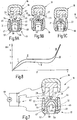
- FIG. 8 illustrates to an infinitesimal small cross section segment of the branches of the instrument.
- the forces specified in the diagram refer to the entire length of the abutment element, all infenitesimal elements projected (eg accumulated) values. Alternatively, this characteristic can also be determined by moving the first industry and the second industry in a parallel alignment to each other (closed).
- the abutment 35 deforms, as in FIG. 9C shown.
- the webs 52, 53 are lifted from the inner sides of the legs 31, 32 and lie against the side surfaces of the wall portion 25 at.
- the side walls 44, 45 buckle, as a comparison of FIGS. 9A to 9C indicates increasingly and the transverse wall 39 deviates correspondingly down.
- the sectors ride on each other or come to the end of the sealing electrodes 27, 28 and 33, 34 and the jaw part is closed. From here there is no further compression of the abutment, except there is still tissue in the jaw part.
- a part of the abutment 35 for example, the transverse wall 39, come into contact with at least one of the retaining plates 55 to 57.
- the abutment 35 already deforms before the cutting electrode 26 comes into contact with the tissue support surface 36.
- the cutting and sealing processes find themselves at the same time instead of.
- different tissue movements occur at different locations.
- the tissue support surface 36 approaches more and more of the cutting electrode 26.
- the restoring force of the abutment 35 predetermines the cutting force and essentially ensures the cutting movement.
- the total clamping force applied between the branches 18, 19 is significantly higher than the force between the abutment 35 and the cutting electrode 26 and may, for example, be 10N to 30N, for example 22N in the middle of the branch.
- the abutment 35 on the cutting electrode 26 only sets a force of 2N to 8N, so that the residual force between the sealing electrodes 27, 33, 28, 34 becomes effective. In this way, both can be achieved: A secure seal or coagulation due to high forces and a clean cut performed substantially purely electrically.
- the values of the closing force given above depend on the design, in particular the size of the branches of the surgical instrument. Altered geometric conditions, for example, for an open-surgical or machine-controlled application may result in different closing force values.
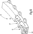
- the abutment 35 may also have a hollow chamber 63 instead of the open recess 37, as it FIG. 10 illustrated.
- recesses 49 to 51 may be provided. However, such recesses can also be omitted.
- the hollow chamber 63 may be round, trapezoidal, rectangular, star-shaped or formed in similar shapes.
- abutment 35 is formed generally or in zones as open-cell or closed-cell foam.
- an abutment 35 which has at least one outwardly open recess 37 and / or one or more hollow chambers 63.
- the recess 37 or the hollow chamber 63 are designed so that the abutment 35, when considering an infinitesimally small cross-sectional segment, during compression and reexpanding a force-displacement spring characteristic with a plateau-like region II, V is formed.
- the abutment 35 preferably provides a force between 2N and 4N, considering an idealized parallel termination of abutment and cutting electrode.
- the path range x in which the spring characteristic shows the plateau II, IV, is preferably as large as the thickness of the tissue to be cut, and is for example in the range of 0.2 to 1.5 mm, preferably the thickness is 1 mm, particularly preferably 0.5 mm. This ensures that the force exerted on the tissue remains essentially constant during the cutting process in the effective working area.
- Reference numerals 11 Facility 12 instrument 13 electric wire 14 Device for powering the instrument 15 Handle 16 Tool 17 shaft 18 first (upper) branch 19 second (lower) industry 20 joint 21, 22 Legs of the U-section of the first branch 18 23 cutting element 24 foot section 25 wall section 26 cutting electrode 27, 28 first coagulation, sealing electrode 29, 30 mounting plates 31, 32 Legs of the U-section of the second branch 19 33, 34 second coagulation, sealing electrode 35 abutment 36 Tissue contact surface 37 recess 38
- Floor space 39-43 transverse walls 39a-43a Recesses of the transverse walls 39, 40, 41, 42, 43 44, 45 Side walls / bottom of the recess 37 46 Roof section, floor 47, 48 feet 49-51 recesses 52, 53 centering 54
- Cutting electrode impingement 55-57 retaining element 58, 59 tabs 60 Tissue contact surface 61 RF generator 62 transformer 63 hollow
Landscapes
- Health & Medical Sciences (AREA)
- Surgery (AREA)
- Life Sciences & Earth Sciences (AREA)
- Engineering & Computer Science (AREA)
- Heart & Thoracic Surgery (AREA)
- Veterinary Medicine (AREA)
- Public Health (AREA)
- General Health & Medical Sciences (AREA)
- Animal Behavior & Ethology (AREA)
- Medical Informatics (AREA)
- Molecular Biology (AREA)
- Biomedical Technology (AREA)
- Nuclear Medicine, Radiotherapy & Molecular Imaging (AREA)
- Physics & Mathematics (AREA)
- Otolaryngology (AREA)
- Plasma & Fusion (AREA)
- Ophthalmology & Optometry (AREA)
- Chemical & Material Sciences (AREA)
- Chemical Kinetics & Catalysis (AREA)
- Vascular Medicine (AREA)
- Epidemiology (AREA)
- Surgical Instruments (AREA)
- Grinding-Machine Dressing And Accessory Apparatuses (AREA)
Abstract
Description
- Die Erfindung betrifft ein manuell oder maschinell geführtes Instrument, mit dem biologisches Gewebe gefasst, koaguliert und getrennt oder nur koaguliert werden kann.
- Ein solches als Schere ausgebildetes Instrument ist aus der
US 2004/0049185 A1 bekannt. Das Instrument weist zwei Branchen auf, die über ein Scharnier miteinander verbunden sind und dadurch aufeinander zu und voneinander weg geschwenkt werden können. Die Branchen können zwischen einander Gewebe fassen. Beide Branchen weisen jeweils einen etwa U-förmigen Querschnitt auf, wobei die Enden der Schenkel des U-förmigen Querschnitts die Koagulationselektroden bilden. Diese koagulieren dazwischen gefasstes Gewebe, wenn die beiden Branchen an die Pole einer entsprechenden Stromquelle angeschlossen sind. - Eine der Branchen weist zusätzlich eine Schneidelektrode auf, die zentrisch zwischen den Koagulationselektroden über diese hinaus vorstehend angeordnet ist. Die gegenüber liegende Branche weist ein Widerlager aus einem elastischen Material auf, in das die Schneidelektrode unter elastischer Verformung des Widerlagers eindringen kann. Damit wird vor der Schneidelektrode liegendes biologisches Material an die Schneidelektrode angedrückt.
- Weiter ist aus der
US 2005/ 0 171 533 A1 ein ähnliches Instrument mit zwei Branchen, die jeweils Koagulationselektroden tragen, und mit einer Schneidelektrode bekannt, die in einer der Branchen zwischen zwei Koagulationselektroden angeordnet ist. In der gegenüber liegenden Branche ist eine Nut zur Aufnahme der Schneidelektrode vorgesehen. Am Boden der Nut ist ein Isolator aus elastischem Material angeordnet. - Bei den Instrumenten der oben genannten Bauart findet der Schneidvorgang des gefassten Gewebes zwischen der Schneidelektrode und dem Widerlager statt. Dabei kommt es darauf an, dass das Gewebe durch Einwirkung des von der Schneidelektrode ausgehenden elektrischen Stroms sicher und vollständig durchtrennt wird, wobei eine mechanische Schneidwirkung der Schneidelektrode nicht gewünscht ist. Bei der praktischen Anwendung unterliegt die Menge bzw. Dicke sowie die Beschaffenheit des zwischen den Branchen gefassten Gewebes gewissen Variationen. Dennoch soll trotz dieser wechselnden Bedingungen jeweils ein sauberer Schnitt des Gewebes und eine gute Koagulation der erzeugten Gewebesäume erreicht werden. Um eine gute Koagulation zu erreichen, muss das Gewebe mit relativ hoher Kraft zwischen den Koagulationselektroden gefasst sein. An der Schneidelektrode ist hingegen eine deutlich geringere Kraft gewünscht.
- Davon ausgehend ist es Aufgabe der Erfindung, ein Konzept für ein maschinell oder manuell geführtes Instrument anzugeben, mit dem sich die genannten Anforderungen erfüllen lassen.
- Diese Aufgabe wird mit dem Instrument nach Anspruch 1 gelöst:
- Das Instrument weist eine erste Branche mit mindestens einer ersten Koagulations- bzw. Versiegelungselektrode zur Koagulation biologischen Materials auf. Vorzugsweise sind an der ersten Branche zwei erste Versiegelungselektroden vorgesehen, die sich im Abstand zueinander erstrecken und zwischen denen ein Freiraum ausgebildet ist. In dem Freiraum ist ein vorzugsweise elektrisch isolierender Schneidelektrodenträger angeordnet, der die Schneidelektrode trägt. Dazu kann der Schneidelektrodenträger einen die Versiegelungselektroden überragenden mittigen wandartigen Vorsprung aufweisen, der an seinem freien Ende die Schneidelektrode trägt.
- Die zweite Branche weist wenigstens eine zweite Versiegelungselektrode, vorzugsweise zwei im Abstand zueinander angeordnete Versiegelungselektroden auf. In dem zwischen den zweiten Versiegelungselektroden vorhandenen Freiraum ist ein Widerlager angeordnet, das vorzugsweise als gesondert vorgefertigtes Element aus elastischem Material ausgebildet ist. Dieses Widerlager weist mindestens eine nach außen offene Ausnehmung und/oder wenigstens eine Hohlkammer auf. Diese eine oder mehrere Ausnehmungen und/oder Hohlkammern können zur gezielten Einstellung der Federkennlinie des Widerlagers genutzt werden. Damit kann erreicht werden, dass die von dem Widerlager im Ziel-Arbeitsbereich ausgeübte, gegen das Schneidelement bzw. die Schneidelektrode gerichtete Kraft während des gesamten Schneidvorgangs des Gewebes einen Grenzwert von zum Beispiel 1N bis 2N nicht unterschreitet und einen Grenzwert von zum Beispiel 3N oder 4N bzw. 7N oder 8N nicht übersteigt. Im Instrument sind Schneidelement und Widerlager mechanisch über das Gelenk des Maulteils gekoppelt. D.h. über die winklige Anordnung zueinander wird das Widerlager von der Schneidelektrode stets in einer Art Walk-Bewegung komprimiert, d.h. nicht und vorzugsweise nie vollständig parallel komprimiert. Zur Betrachtung des Federverhaltens des Widerlagers und insbesondere dessen Geometrie, ist es deshalb sinnvoll, nur ein sehr kurzes, infinitesimal kleines Segment des Widerlagers zu betrachten. Bei dieser Betrachtung eines Widerlager-Segmentes, ist eine nichtlineare Kraft-Weg-Kennlinie beim Zusammendrücken des Widerlagers erreichbar. Insbesondere kann diese Kraft-Weg-Kennlinie einen Abschnitt mit nahezu konstanter Kraft aufweisen. Eine an diesen Abschnitt angelegte Gerade schneidet den Nullpunkt des Kraft-Weg-Diagramms nicht. Im Idealfall verläuft eine solche Gerade fast parallel zur Weg-Achse (Abszisse). Die Kraft-Weg-Kennlinie hat dementsprechend ein Plateau.
- Es können eine oder mehrere Ausnehmungen und/oder eine oder mehrere Hohlkammern im Widerlager vorgesehen sein. Die Ausnehmungen sind nach außen offen, d.h. sie sind nicht allseits von dem Widerlager umschlossen, sondern treten als Öffnung an dessen Oberfläche zutage. Vorzugsweise weist auch die Branche, zumindest einen Durchbruch auf, der mit der Ausnehmung des Widerlagers in Verbindung steht. So können gasförmige oder flüssige Fluide ungehindert aus der Ausnehmung austreten, wenn das Widerlager komprimiert wird. Eine Verhärtung des Widerlagers durch in der Ausnehmung eingeschlossene Flüssigkeiten oder gar durch Koagulation solcher Flüssigkeiten wird vermieden. Alternativ können die Ausnehmungen auch den Querschnitt des Widerlagers ganz oder teilweise durchdringend angeordnet sein.
- Bei einer alternativen Ausführung ist es möglich, die Branchen gegenüber den Ausnehmungen des Widerlagers mit einem Verschlusselement, z.B. einem Deckel, auszubilden. In diesem Fall können die oben beschriebenen Fluide entweder weiterhin aus der Ausnehmung des Widerlagers austreten oder das Verschlusselement ist so gestaltet, dass die oben beschriebenen Fluide weiterhin aus den Ausnehmungen des Widerlagers austreten können.
- Die großflächig offene Ausnehmung kann das Eindringen und wieder Austreten von Fluiden gestatten. Durch die Größe der Öffnung wird verhindert, dass es beim Betrieb in Flüssigkeit (zum Beispiel Blut) durch die Kompression und Dekompression des Widerlagers zu einer Pumpwirkung der Flüssigkeit kommt. Selbst wenn aufgrund der Wärmefreisetzung an dem Instrument Flüssigkeit zum Beispiel Blut koaguliert und verklumpt, bleiben die Öffnungen nach außen frei, so dass das weitere Ein- und Ausfedern nicht behindert wird.
- Als Gewebeauflagefläche wird die Oberfläche des Widerlagers bezeichnet, die dem Schneidelement gegenüberliegt und gegen die das Schneidelement eine Kraft aufbringt, gegebenenfalls auch mit dazwischenliegendem Gewebe. Die Ausnehmung kann durch eine der Gewebeauflagefläche abgewandte Nut oder auch eine Reihe von kurzen voneinander durch Querwände getrennten Nuten ausgebildet sein. Eine solche Nut wird seitlich von Nutwänden begrenzt, die den oberen geschlossenen Teil des Widerlagers tragen, der die Gewebeauflagefläche festlegt. Beim Schließen der Branchen drückt die Schneidelektrode das Widerlager zusammen, womit die unter der Gewebeauflagefläche liegende Ausnehmung zumindest teilweise kollabiert.
- Alternativ oder zusätzlich können ein oder mehrere Ausnehmungen vorgesehen sein, die die Gewebeauflagefläche durchsetzen und somit zu der die Schneidelektrode tragenden Branche hin offen sind. Solche Ausnehmungen können insbesondere eine Verbindung mit einer oder mehreren rückseitigen, d.h. von der Gewebeauflagefläche abgewandten Ausnehmungen oder Hohlkammern des Widerlagers ergeben. Die von der Gewebeauflagefläche abgewandten Ausnehmungen oder Hohlkammern sind durch von der Gewebeauflagefläche weg divergierende Wände definiert. Mit dieser Konfiguration lässt sich der gewünschte Kennlinienverlauf besonders leicht und zuverlässig erreichen. Die Wände des Widerlagers können dabei (wie auch bei anderen Ausführungsformen) in Richtung von der Gewebeauflagefläche weg eine konstante Wandstärke aufweisen.
- Die an dem Widerlager ausgebildete von der Gewebeauflagefläche weg weisende offene Ausnehmung kann eine oder mehrere Querwände aufweisen. Solche Querwände können eine einheitliche Wandstärke aufweisen oder auch einen Schwächungsbereich haben. Der Schwächungsbereich kann auch ganz entfallen und als Ausschnitt ausgebildet sein. Damit nimmt die Querwand nicht mehr den gesamten Querschnitt der Nut ein. Beim Komprimieren des Widerlagers kann ein teilweiser Kollaps der Ausnehmung stattfinden. Mithilfe der Querwände kann ein Absinken der von dem Widerlager aufgebrachten Kraft aufgrund des teilweisen Kollaps der Ausnehmung verhindert werden. Die Querwände verstärken nicht nur die Gesamtfederkraft des Widerlagers, sondern erzeugen auch die notwendige Kraftkomponente, damit sich das Widerlager auch in Querrichtung bei Druckentlastung wieder rückstellen kann. Die Vorsehung des Schwächungsbereichs oder eines Ausschnitts in den Querwänden vermeidet eine Krafterhöhung, die bei maximaler Kompression auf Anschlag und daraus hervorgerufener Quetschung entstehen kann. Des Weiteren erleichtern die Querwände auch das Handling und die Handhabung des in der Praxis sehr filigranen Widerlagers, denn sie verleihen diesem eine Grundstabilität und verhindern einen Kollaps der gesamten Struktur im nicht eingebauten Zustand.
- In eingebautem Zustand ist das Widerlager in der Branche fixiert. Dazu kann das Widerlager seitliche Vorsprünge in Form von Füßen aufweisen, denen komplementäre Ausnehmungen in der Branche zugeordnet sind. Die seitlich abstehenden Vorsprünge fassen in die Ausnehmungen der Branche und halten das Widerlager. Zusätzlich kann ein Halteelement zur Fixierung des Widerlagers vorgesehen sein. Dieses drängt die Füße tragenden Wände des Widerlagers voneinander weg nach außen und sorgt für den festen Sitz der Füße in den Ausnehmungen.
- Als Material für das Widerlager wird vorzugsweise ein biokompatibles Silikon mit einer Härte von 50 Shore verwendet, womit sich die gewünschte Federkraft und der oben beschriebene plateauartige Kraftverlauf der Kraft-Weg-Kennlinie leicht erreichen lassen. Sind die Gewebeauflagefläche durchsetzende Ausnehmungen vorgesehen, sind diese vorzugsweise zu beiden Seiten eines streifenförmigen Schneidelektroden-Auftreffbereichs der Gewebeauflagefläche angeordnet. Vorzugsweise ergibt sich eine symmetrische Form des Querschnitts des Widerlagers. Dies gilt insbesondere, wenn die Schneidelektrode mittig auf das Widerlager auftrifft. Entlang des Schneidelektroden-Auftreffbereichs der Gewebeauflagefläche können zu beiden Seiten Stege angeordnet sein, die vorzugsweise oben eben mit dem Schneidelektroden-Auftreffbereich abschließen. Die Stege können an der inneren Flanke der Branche anliegen und bewirken eine Zentrierung des Widerlagers sowohl im Ruhzustand als auch im eingefederten, d.h. ganz oder teilweise zusammengedrückten Zustand. Die Stege können mit gleichen oder wechselnden Abständen und jeweils paarweise auf beiden Seiten oder auch unpaarig angeordnet sein. Es ist auch möglich, dass die Oberfläche der Stege, wannenförmig oder keilförmig ausgebildet ist, um die Zentrierfunktion des Schneidelements zu verstärken. Es ist auch möglich, dass die Gewebeauflagefläche des Schneidelektroden-Auftreffbereichs teilweise gebogen, wannenförmig oder keilförmig ausgebildet sein kann, um diese Zentrierfunktion zu unterstützen.
- Durch den vorzugsweise flächigen Anschluss der Stege mit dem Schneidelektroden-Auftreffbereich wird außerdem verhindert, dass das Schneidelement von dem Schneidelektroden-Auftreffbereich seitlich abrutscht, wie es bei asymmetrischer Verformung des Widerlagers sonst vorkommen könnte. Eine solche asymmetrische Verformung hätte auch ein seitliches Abdrängen der Schneidelektrode zur Folge. Die stützenden Stege stabilisieren somit auch die unter Umständen seitlich nachgiebige Schneidelektrode und verhindern deren Abkippen. Damit sorgen sie auch für eine symmetrische Ausbildung der Gewebeaufnahmeräume direkt neben der Schneidelektrode, also zwischen der Schneidelektrode und den Versiegelungselektroden.
- Durch das gewünschte Verhalten des Widerlagers, nämlich ein Einknicken der Seitenwände und gewissermaßen ein Umschnappen derselben, muss eine symmetrische Belastung des Widerlagers sichergestellt sein. Eine asymmetrische Belastung könnte sonst zu einer asymmetrischen Verformung des Widerlagers führen. Die stützenden Stege erfüllen hier eine wichtige Funktion, indem sie ein seitliches Abkippen, d.h. schräges Einfedern des Schneidelektroden-Auftreffbereichs bei unsymmetrischer Belastung und somit eine asymmetrische Verformung minimieren. Damit wird auch ein Abgleiten der Schneidelektrode zu einer Seite des Widerlagers hin vermieden. Das Instrument wird außerdem somit auch gegen Kräfte unempfindlich, die bei der praktischen Anwendung auftreten können, wenn beispielsweise das gefasste Gewebe einem seitlichen Zug ausgesetzt ist.
- Die die Schneidelektrode tragende Branche weist am proximalen Ende einen Gewebeanschlag auf. Dieser Gewebeanschlag kann in das die Schneidelektrode aufweisende Schneidelement integriert sein und verhindern, dass beim Schneiden von Gewebe Teile desselben in Richtung auf das die Branchen verbindende Gelenk hin hinter die Schneidelektrode des Schneidelements rutschen. Somit wird ein Lochstanzeffekt im Gewebe verhindert und das gesamte gefasste Gewebe auch geschnitten. Das Widerlager kann dazu an seinem proximalen Ende einen Gleitbereich für diesen Gewebeanschlag aufweisen, der vorzugsweise eine zur Gelenkachse konzentrische kreissegmentförmige Ausbildung hat. Alternativ kann der Gewebeanschlag Teil des Widerlagers sein und an dem Schneidelement entlang gleiten. Die proximale Seite des Widerlagers ist jedenfalls so geformt, dass es ungeachtet der Relativposition der Branchen zueinander stets mit dem Gewebeanschlag abschließt.
- Mit dem erfindungsgemäßen Instrument kann zwischen Widerlager und Schneidelektrode eine Schnittkraft von ca. 2N bis 4N eingestellt werden, welche bei geschlossenen Branchen auf das zu trennende Gewebe wirkt. Dadurch kann die auf die Schneidelektrode einwirkende Kraft minimiert werden. Zusätzlich wird sichergestellt, dass das Gewebe vollständig getrennt wird. Ein hauchdünner Gewebeteil zwischen den getrennten Gewebeteilen, wie er in der Anwendung gemäß dem Stand der Technik vorkommen kann, wird durch die Sicherstellung und präzise Einstellung der Schnittkraft vermieden. Die Schließkraft der Branchen, die in Branchenmitte etwa 22N betragen kann, kann somit zum weitaus größten Teil für den Versiegelungsprozess genutzt werden. Somit ist die Schnittkraft lediglich so groß wie nötig (ca. 2N bis 4N) wohingegen die an den Versiegelungselektroden vorhandene Kraft so groß wie möglich ist. Das Widerlager bringt durch seine Nachgiebigkeit, und damit Rückfedermöglichkeit, nur etwas mehr als die zum Schneiden notwendige Schneidkraft auf das Gewebe zwischen Widerlager und Schneidelektrode auf. Die übrige Schließkraft entfällt dann auf die Versiegelungselektroden. Der vorgeschriebene Schließprozess des Instruments gilt im Wesentlichen unabhängig davon, ob Gewebe zwischen den Branchen gefasst ist oder nicht.
- Mit der genannten Maßnahme werden günstige Stromdichteverhältnisse an der Schneidelektrode geschaffen. Durch das korrekte Andrücken des Gewebes an die Schneidelektrode wird eine hohe Stromdichte an der Schneidelektrode erreicht, ohne das Gewebe mechanisch zu trennen. Die Nachgiebigkeit des Widerlagers sorgt also auch dafür, dass beim Fassen und Manipulieren von Gewebe mit diesem Branchenpaar das Gewebe trotz des schmalen, kantigen Schneidelements so wenig wie möglich traumatisiert wird oder mechanischen Schaden nimmt. Außerdem dient das Widerlager als Toleranzausgleich, der immer sicherstellt, dass der Großteil der Schließkraft auf die Versiegelungselektroden wirkt und nur ein kleinerer auf die Schneidelektrode bzw. das Schneidelement.
- Durch die spezifische Ausbildung des Gegenlagers ist auch eine gewisse Beweglichkeit in Branchenlängsrichtung gegeben, die zumindest im Rahmen der durch die elastische Verformung der Branchen und des Schneidelements verursachten Bewegungen liegt. Dies erschließt sich aus der nachfolgenden Kurzbeschreibung des Schließens des Instruments bei zunehmender Schließkraft ohne zwischen den Branchen gefasstes Gewebe:
- Zunächst berührt das Schneidelement die Gewebeauflagefläche des Widerlagers unmittelbar am proximalen Ende. Bei weiterer Kraftaufbringung federt das Widerlager unter dem Schneidelement ein, wobei sich auch das Schneidelement und die Branchen geringfügig elastisch verformen können. Durch das Schließen weicht das Widerlager auch etwas in vorzugsweise distaler Branchenlängsrichtung aus.
- Das Schneidelement taucht idealerweise senkrecht und mittig in das Widerlager ein. Die Gewebeauflagefläche des Widerlagers baucht ein - es entsteht eine Vertiefung. Die schrägen Wände des Widerlagers wölben sich in Richtung zu den Versiegelungselektroden hin aus. Die Oberseiten der stützenden Stege des Widerlagers legen sich an die Seitenflächen des Schneidelements an und zentrieren es dadurch mittig im Instrument. Dicke und Abstand der stützenden Stege sind dabei so gewählt, dass die dazwischen vorhandenen Ausnehmungen als Gewebeaufnahmeräume dienen können. Die Branchen sind komplett geschlossen, wenn die Versiegelungselektroden der beiden Branchen aufeinander liegen und die entsprechende Schließkraft von zum Beispiel 22N in Branchenmitte wirkt. Um elastische Verformungen der Branchen auszugleichen sind diese dabei so geformt, dass sich zuerst die Versiegelungselektrodenflächen am distalen Ende derselben berühren, bevor der vorhandene Dreieckspalt durch zunehmende Schließkraft und daraus resultierende elastische Verbiegung der Branchen allmählich geschlossen wird. Die Versiegelungselektroden der Branchen zueinander können so gestaltet sein, dass sie bei einem Abstand von zum Beispiel 0,1 mm einen Parallelspalt festlegen. Weil keine das weitere Schließen verhindernden Anschläge oder Abstandshalter vorgesehen sind, wird der Spalt beim weiteren Schließen am distalen Ende Null. Bei steigender Schließkraft verformen sich die Branchen dann zunehmend elastisch und der Spalt wird auch in einiger Distanz zum distalen Ende nahe Null.
- In der Zeichnung sind Ausführungsbeispiele der Erfindung veranschaulicht. Es zeigen:
-
Fig. 1 ein Instrument zum Fassen, Koagulieren und Trennen von biologischem Gewebe angeschlossen an ein speisendes Gerät, in schematischer Darstellung, -
Fig. 2 das Werkzeug des Instruments nachFigur 1 , in vergrößerter perspektivischer Darstellung, -
Fig. 3 das Werkzeug nachFigur 2 in gewendeter Position, in perspektivischer Darstellung vor dem Fixieren des Widerlagers, -
Fig. 4 das Werkzeug nachFigur 3 mit fixiertem Widerlager, -
Fig. 5 das Widerlager in perspektivischer Darstellung mit Blick auf seine Gewebeauflagefläche, -
Fig. 6 das Widerlager nachFigur 5 mit Blick auf seine unterseitige Ausnehmung, -
Fig. 7 eine schematische Skizze zur Veranschaulichung der elektrischen Versorgung des Instruments, -
Fig. 8 die Kraft-Weg-Kennlinie (Federkennlinie) eines infinitesimal kleinen Segmentes des Widerlagers des Werkzeugs nach denFiguren 2 bis 4 , -
Figur 9A-9C das Werkzeug im Querschnitt, in verschiedenen Positionen beim Schließen, und -
Fig. 10 eine abgewandelte Ausführungsform des Widerlagers in schematisierter perspektivischer Darstellung. - In
Figur 1 ist eine Einrichtung 11 veranschaulicht, zu der ein Instrument 12 zum Fassen, Koagulieren und Trennen von biologischem Gewebe gehört, das über ein Kabel 13 mit einem speisenden Gerät 14 verbunden ist. Das Instrument 12 kann, wie dargestellt, ein Instrument zur laparoskopischen Chirurgie oder auch anderweitig ausgebildet sein. Zum Beispiel kann es als scherenartiges Instrument für die offenchirurgische Behandlung wie auch als Instrument zur endoskopischen Behandlung ausgebildet sein. Es kann außerdem einen Griff 15 zur manuellen Führung oder auch einen Anschluss zur maschinellen Führung (nicht dargestellt) aufweisen. Das Instrument 12 kann somit direkt von einem Anwender oder von einem Roboter geführt werden. Unabhängig davon weist es ein Werkzeug 16 auf, das in dem Ausführungsbeispiel nachFigur 1 an dem distalen Ende eines länglichen Schafts 17 des Instruments 15 angeordnet ist. Der Aufbau des Werkzeugs 16 ist nachfolgend erläutert: - Das gesondert in
Figur 2 veranschaulichte Werkzeug 16 weist eine erste, inFigur 2 obere Branche 18 und eine zweite, inFigur 2 untere Branche 19 auf, die an einem Gelenk 20 miteinander verbunden sind, so dass zumindest eine der Branchen 18, 19 gegen die andere geschwenkt werden kann. Im Ausführungsbeispiel nachFigur 2 ist die untere Branche beweglich. Alternativ können beide Branchen 18, 19 oder auch lediglich die obere Branche 19 beweglich ausgebildet sein. Nachdem die räumliche Orientierung der Branchen 18, 19 von der Position des Instruments 15 abhängt, wird die obere Branche 18 nachfolgend als erste Branche und die untere Branche 19 nachfolgend als zweite Branche bezeichnet. - Die erste Branche 18 besteht vorzugsweise aus einem elektrisch leitenden Material, insbesondere Metall, und weist einen U-förmigen Querschnitt auf. Entsprechend ist zwischen zwei zueinander im Abstand verlaufenden Schenkeln 21, 22 ein nutartiger Zwischenraum ausgebildet, in dem ein Schneidelement 23 angeordnet ist. Dieses besteht aus einem elektrisch isolierenden Material, beispielsweise Kunststoff oder Keramik. Es weist einen in seiner Grundform etwa T-förmigen Querschnitt auf. Von einem unteren plattenartigen Fußabschnitt 24 ragt ein mittlerer Wandabschnitt 25 auf, der an seinem schmalen, der anderen Branche 19 zugewandten Seite eine Schneidelektrode 26 trägt. Diese kann durch ein Metallblech gebildet sein, das in den Wandabschnitt 25 eingefügt und dort gehalten ist. Die Schneidelektrode 26 liegt nur an der der anderen Branche 19 zugewandten Seite, ihrer Schneidefläche frei und überragt hier die schmale Stirnseite des Wandabschnitts 25 nicht oder lediglich um wenige Zehntel-Millimeter.
- Die beiden Schenkel 21, 22 der Branche 19 werden durch jeweils zwei Seitenflächen, eine Schmalseite und eine quer zu dieser Schmalseite angeordnete Endfläche gebildet. Jeder Schenkel 21, 22 umfasst eine erste innere Seitenfläche und eine zweite äußere Seitenfläche. Die beiden ersten inneren Seitenflächen der Schenkel 21, 22 bilden zusammen mit einer Bodenfläche die Innenform des U-förmigen Querschnitts der Branche, also die Branchenaußenseite. Die beiden langen äußeren Seitenflächen bilden zusammen mit einer Rückenfläche die Außenform des U-förmigen Querschnitts der Branche.. Eine Ebene, die an beiden Schmalseiten der Schenkel 21, 22 aufliegt ist im Wesentlichen parallel zur Schneidefläche der Schneideelektrode 26 angeordnet. Die Versiegelungselektroden 27, 28 der Branche 19 sind im Wesentlichen an der Schmalseite in einem Winkel, vorzugsweise einem spitzen Winkel bezüglich der ersten Seitenfläche eines Schenkels 21, 22 angeordnet. Der Übergang einer Versiegelungselektrode 27, 28 in die erste und in die zweite Seitenfläche der Schenkel 21, 22 ist gerundet ausgebildet. Dabei kann sich der Radius der beiden Übergänge voneinander unterscheiden. Vorzugsweise ist der Radius des Übergangs einer Versiegelungselektrode 27, 28 zur ersten inneren Seitenfläche geringer, besonders vorzugsweise 4 x kleiner als der Radius des Übergangs einer Versiegelungselektrode zur zweiten äußeren Seitenfläche des Schenkels 21, 22. Die Versiegelungselektroden 27, 28, die an der Schmalseite der Schenkel angeordnet sind, reichen über die vorbeschriebenen Radien bis in die erste und die zweite Seitenfläche der Schenkel 21, 22. Das Werkzeug 16 weist mindestens eine Versiegelungselektrode 27, vorzugsweise jedoch zwei derartige erste Versiegelungselektroden auf, zwischen denen das Schneidelement 23 mit der Schneidelektrode 26 angeordnet ist. Zur Verbesserung der Übersichtlichkeit sind das Schneidelement 23 mit der Schneidelektrode 26 und die Versiegelungselektroden 27, 28 in den
Figuren 3 und 4 veranschaulicht. WieFigur 2 zeigt, kann das Schneidelement 23 in der Branche 18 formschlüssig verankert, und beispielsweise durch entsprechende Befestigungsbleche 29, 30 gegen das Austreten an der Branchenrückseite gesichert sein. Das Schneidelement 23 ist in diesem Fall an der ersten Branche 18 starr, d.h. unbeweglich gelagert. Eine bewegliche Lagerung ist jedoch bei jeder Ausführungsform als Abwandlung möglich. Auch das Schneideelement 23 selbst kann eine Bewegung ermöglichen oder nachgiebig oder elastisch ausgebildet sein. - Die zweite Branche 19 weist ähnlich wie die erste Branche und wie aus
Figur 2 erkennbar einen U-förmigen Querschnitt mit Schenkeln 31, 32 auf, wobei an den Schmalseiten der beiden Schenkel 31, 32 des U-Querschnitts zweite Versiegelungselektroden 33, 34 angeordnet sind. Die Versiegelungselektroden 33, 34 der zweiten Branche 19 sind im geschlossenen Zustand des Instruments komplementär zu den Versiegelungselektroden 27, 28 der ersten Branche 18 angeordnet, was dazu führt, dass der spitze Winkel zwischen den Versiegelungselektroden 33, 34 und der zweiten Seitenfläche gebildet wird. Ansonsten gilt die Beschreibung der Versiegelungselektroden 27, 28 auch für die Versiegelungselektroden 33, 34 entsprechend. Die Versiegelungselektroden 33, 34 können, wie auch die ersten Versiegelungselektroden 27, 28, jeweils mit einer Reihe von isolierenden Feldern versehen sein, wobei die isolierenden Felder der ersten Versiegelungselektroden 27, 28 so gegen die isolierenden Felder der zweiten Versiegelungselektroden 33, 34 in Elektrodenlängsrichtung versetzt sind, dass ein elektrischer Kurzschluss bei Berührung der Branchen 18, 19 ausgeschlossen ist. - Zwischen den beiden Schenkeln 31, 32 der zweiten Branche 19 ist ein nutartiger Freiraum ausgebildet, in dem ein Widerlager 35 angeordnet ist, das vorzugsweise als gesondertes Element gefertigt ist. Das Widerlager 35 ist in den
Figuren 5 und 6 gesondert und vergrößert veranschaulicht. Es ist vorzugsweise aus einem elastischen Werkstoff wie beispielsweise einem Elastomer, Silikon, Silikongummi, Gummi oder dergleichen, ausgebildet. An seiner der Schneidelektrode 26 zugewandten Seite weist das Widerlager 25 eine ebene oder leicht gewölbte Gewebeauflagefläche 36 auf. Im nicht komprimierten Zustand des Widerlagers ist die Gewebeauflagefläche 36 im Wesentlichen parallel zu einer auf den Schmalseiten der Schenkel 31, 32 liegenden Ebene angeordnet. Die Gewebeauflagefläche 36 weist mittig einen streifenförmigen Schneidelektroden-Auftreffbereich 54 auf, der der Schneidelektrode 26 unmittelbar gegenüberliegt und an dem die Schneidelektrode 26 beim gelenkförmigen Schließen des Werkzeugs 16 zur Berührung kommt. - Das Widerlager 35 ist vorzugsweise einstückig ausgebildet, beispielsweise als Spritzguss-, Spritzpress, Press- oder Sinterteil, d.h. es besteht nahtlos aus einem einheitlichen Material. Vorzugsweise weist es auf seiner der Gewebeauflagefläche 36 abgewandten Seite mindestens eine Ausnehmung 37 auf (
Figur 6 ), die eine Grundfläche 38 des Widerlagers 35 durchsetzt und somit nach außen offen ist. Die Ausnehmung 37 kann wie ausFigur 6 ersichtlich als eine längliche durch Querwände 39, 40, 41, 42, 43 in Kammern unterteilte Nut oder dergleichen, ausgebildet sein. Die Querwände 39, 40, 41, 42, 43 können in gleichen oder unterschiedlichen Abständen zueinander angeordnet sein. Sie können zu der Hauptgrundfläche 38 rechtwinklig oder auch geneigt angeordnet sein. - Die Querwände 39, 40, 41, 42, 43 können einen geschwächten, d.h. mit geringerer Wandstärke versehenen Abschnitt aufweisen. Auch ist es möglich, die Querwände 39 bis 43, wie dargestellt, bodenseitig jeweils mit einer vorzugsweise gerundeten, maulartigen Ausnehmung 39a, 40a, 41a, 42a, 43a zu versehen. Über Größe und Form der Ausnehmung 39a, 40a, 41a, 42a, 43a lässt sich die Steifigkeit jeder Querwand 39 bis 43 gezielt festlegen und somit die Nachgiebigkeit des Widerlagers 35 insgesamt beeinflussen. Auch ist es möglich, die Querwände 39 bis 43 rechtwinklig zu der Grundfläche 38 oder auch in einer Neigung zu dieser anzuordnen. Damit, und mit der Größe und Form der Ausnehmung 39a, 40a, 41a, 42a, 43a, lässt sich nicht nur die Nachgiebigkeit insgesamt, sondern auch die Form der erzielbaren Federkennlinie und die Verformung steuern.
- Die Ausnehmung 37 ist in Längsrichtung seitlich von Wänden 44, 45 begrenzt, die zusammen mit einem die Gewebeauflagefläche 36 tragenden Dachabschnitt 46 einen trapezförmigen Abschnitt der Nut bzw. Ausnehmung 37 festlegen. Der Dachabschnitt 46 bildet zugleich den Boden der nutartigen Ausnehmung 37. Die den trapezförmigen Teil der Ausnehmung 37 begrenzenden Teile der Seitenwände 44, 45 sind vorzugsweise aufeinander zu geneigt, und im Querschnitt gerade ausgebildet wie
Figur 7 zeigt. Im Ausführungsbeispiel gemäßFigur 7 weisen die Seitenwände einen konstanten Querschnitt auf. Die Querschnittsform hat einen Einfluss auf die Federkennlinie des Widerlagers 35 und kann entsprechend der Anforderungen andere Formen einnehmen. - Weiter können die Seitenwände 44, 45 zueinander parallel verlaufende Abschnitte aufweisen, die Füße 47, 48 zur Befestigung des Widerlagers 35 in der Branche 19 tragen. Den Füßen 47, 48 sind in der Branche 19 vorgesehene komplementäre Ausnehmungen zugeordnet, in die die Füße 47, 48 fassen, um darin gesichert zu sein.
- Das Widerlager 35 kann auch alternativ als Silikon/Metall Verbundteil ausgebildet sein. Dabei können andere Befestigungsmittel als die oben beschriebenen Füße 47, 48 vorgesehen sein. Diese Befestigungsmittel können aus einem anderen Werkstoff als dem elastischen Werkstoff, der die Federkennlinie des Widerlagers prägt, gebildet sein. Trotzdem kann das Widerlager als einstückiges Bauteil betrachtet werden. Weist das Widerlager 35 Befestigungsmittel anderer Art auf, können die oben beschriebenen Ausnehmungen in der Branche 19 anders gestaltet sein, oder komplett fehlen.
- Das Widerlager 35 kann außer der Ausnehmung 37 weitere Ausnehmungen aufweisen. Zum Beispiel können solche Ausnehmungen 49, 50, 51 usw. an der der Grundfläche 38 abgewandten Seite des Widerlagers 35 ausgebildet sein. Solche Ausnehmungen 49 bis 51 können die Gewebeauflagefläche 36 durchsetzend ausgebildet sein und als sich zu beiden Seiten des Widerlagers 35 über dessen gesamte Länge als Reihe erstreckend angeordnet sein. Zwischen jeweils zwei benachbarten Ausnehmungen 49, 51 bzw. 50, 52, können Zentrierstege 52, 53 ausgebildet sein, die vorzugsweise so dimensioniert sind, dass sie im Ausgangszustand, im nicht verformten Zustand, an der Innenflanke des jeweiligen Schenkels 31, 32 der Branche 19 anliegen. An der Oberseite schließen die Zentrierstege 52, 53 sowie die zwischen den weiteren Ausnehmungen vorgesehenen Zentrierstege vorzugsweise eben mit der Gewebeauflagefläche 36 ab. Die Zentrierstege 52, 53 haben eine doppelte Zentrierfunktion: im unbelasteten Zustand zentrieren sie das Widerlager 35 zwischen den Versiegelungselektroden 33, 34 (
Figur 7 und 9A ) und im geschlossenen Zustand des Werkzeugs 16 zentrieren sie das Widerlager 35 in Bezug auf das Schneidelement 23 (Figur 9C ). Es ist auch möglich, dass die Zentrierstege 52, 53 in Richtung der Schenkel 31, 32 abgerundet oder schräg ausgebildet sind um dadurch mehr Raum für die Aufnahme von Gewebe innerhalb der geschlossenen Branchen 18, 19 zu bilden ohne die oben beschriebene Zentrierfunktionen maßgeblich zu verändern. - Die Gewebeauflagefläche 36 besteht somit aus dem schmalen streifenförmigen Schneidelektroden-Auftreffbereich 54, der sich entlang der Länge des Widerlagers 35 erstreckt, und aus den Oberseiten der sich zu beiden Seiten befindlichen Zentrierstege 52, 53. Zwischen den Zentrierstegen 52, 53 u.a. sind jeweils paarweise Ausnehmungen angeordnet, die den Ausnehmungen 49 bis 51 entsprechen und im Querschnitt dreieckförmig sein können.
- Das insoweit beschriebene Widerlager 35 sitzt formschlüssig in der Branche 19 wie es
Figur 7 nahelegt. Zur Befestigung darin, können ausFigur 3 und 4 ersichtliche Halteelemente 55, 56, 57 dienen, die an der Rückseite der Branche 19 anliegen und mit entsprechenden Laschen 58, 59 durch in der Branche 19 vorgesehene Ausnehmungen greifen, um das Widerlager 35 zu fixieren.Figur 3 veranschaulicht die Halteelemente 55, 56, 57 vor dem Fixieren undFigur 4 sowie 7 nach dem Fixieren. InFigur 7 sind zwei Laschen 58, 59 des Halteelements 57 beispielhaft in fixiertem Zustand veranschaulicht. - Das Widerlager 35 und das Schneidelement 23 bilden gemäß der Darstellung in
Figur 2 außerdem einen axialen Gewebeanschlag. Dazu weist das Schneidelement 23 vorzugsweise eine Gewebeanschlagnase mit einer Gewebeanlagefläche 60 auf, die vorzugsweise einem zur Gelenkachse konzentrischen Kreisbogen folgt. Die entsprechende an dem proximalen Ende ausgebildete Fläche des Widerlagers 35 weist eine komplementär passende Gegenfläche auf, die vorzugsweise spaltfrei an der Gewebeanlagefläche 60 anliegt. - Die elektrische Beschaltung des Werkzeugs 16 zeigt
Figur 7 . Eine geeignete elektrische Quelle, beispielsweise in Gestalt eines HF-Generators 61, stellt elektrische Leistung, zum Beispiel in Form einer Wechselspannung mit mehreren Hundert kHz bereit. Diese Spannung kann vorzugsweise direkt an die Branchen 18, 19 angelegt und somit zwischen den ersten Versiegelungselektroden 27, 28 und den zweiten Versiegelungselektroden 33, 34 wirksam werden. Ein von dem HF-Generator 61 gespeister Transformator 62 kann dazu genutzt werden, die HF-Spannung hoch zu transformieren und die Schneidelektrode 26 zu speisen. - Das Instrument 12 und insbesondere das Werkzeug 16 arbeiten wie folgt:
- Im Folgenden wird ein beispielhafter Querschnitt des sich gelenkig schließenden Maulteils betrachtet. Im offenen oder ohne Kraft geschlossenen Zustand des betrachteten Querschnitts hat das Werkzeug 16 den Zustand nach
Figur 7 und 9A . Die Schneidelektrode 26 liegt ohne Kraft an der Gewebeauflagefläche 36 an oder hält einen Abstand zu dieser ein. Zwischen den Branchen 18, 19 gefasstes Gewebe wäre in diesem Querschnitt wenig oder nicht deformiert. - Werden die Branchen 18, 19 im betrachteten Querschnitt nun weiter aufeinander zu bewegt, wie es in
Figur 9B ohne gefasstes Gewebe veranschaulicht ist, nähern sich die ersten Versiegelungselektroden 27, 28 den zweiten Versiegelungselektroden 33, 34 an. Dazwischen gefasstes Gewebe würde geklemmt und deformiert. Außerdem wird das Gewebe bestromt, und dadurch geschnitten und koaguliert. Dabei stellt das Widerlager 35 durch seine Elastizität sicher, dass trotz Gewebeschrumpfung stets Gewebe an der Scheideelektrode anliegt bis dieses Gewebe vollständig geschnitten ist. - Befindet sich kein Gewebe zwischen den Branchen drückt die Schneidelektrode 26 auf die Gewebeauflagefläche 36 und verformt das Widerlager 35. Währenddessen steigt die von dem Widerlager 35 der Schneidelektrode 26 entgegen gerichtete Kraft, wie es in
Figur 8 in einem ersten Abschnitt I der dargestellten Kurve veranschaulicht ist allmählich an, um dann mit dem Abschnitt II ein Plateau zu erreichen. Diese Darstellung des Diagramms gemäßFigur 8 bezieht sich auf eine infinitesimal kleines Querschnittsegment der Branchen des Instruments. Die im Diagramm angegebenen Kräfte beziehen sich auf über die gesamte Länge des Widerlagerelements über, alle infenitesimalen Elemente hochgerechnete (z.B. aufsummierten) Werte. Alternativ kann diese Kennlinie auch ermittelt werden, indem die erste Branche und die zweite Branche in einer parallelen Ausrichtung zueinander aufeinander zu bewegt (geschlossen) werden. - Beim weiteren Zusammenführen der Branchen 18, 19 im betrachteten Querschnitt verformt sich das Widerlager 35, wie in
Figur 9C dargestellt. Die Stege 52, 53 sind von den Innenseiten der Schenkel 31, 32 abgehoben und legen sich an die Seitenflächen des Wandabschnitts 25 an. Die Seitenwände 44, 45 knicken dabei, wie ein Vergleich derFiguren 9A bis 9C zeigt, zunehmend ein und die Querwand 39 weicht entsprechend nach unten aus. Schließlich fahren die Branchen aufeinander auf bzw. kommt es zum Schluss der Versiegelungselektroden 27, 28 und 33, 34 und das Maulteil ist geschlossen. Ab hier findet keine weitere Komprimierung des Widerlagers statt, außer es befindet sich noch Gewebe im Maulteil. In diesem Falle kann ein Teil des Widerlagers 35, z.B. die Querwand 39, in Kontakt mit wenigstens einem der Haltebleche 55 bis 57 kommen. In der Folge darauf ist ein Kraftanstieg III nach Durchlaufen des Plateaus II inFigur 8 zu beobachten. - Während des Schneidens des Gewebes bzw. wenn das geschlossene Maulteil wieder geöffnet wird, richtet sich das deformierte Widerlager 35 wieder auf. Die Rückstellkraft des Widerlagers 35 im betrachteten Querschnitt nimmt wieder ab, siehe Kurvenverlauf IV. Sobald alle Teile des Widerlagers 35, die auf den Halteblechen 55 bis 57 zur Auflage kamen, von diesen wieder abgehoben sind, findet eine Verformung bei relativ konstanter Kraft statt, was dem Kurvenzug V entspricht. Die von dem Widerlager 35 gegen die Schneidelektrode 26 aufgebrachte Kraft auf diesem rücklaufenden Plateaubereich V läge bei Betrachtung eines idealisierten parallelen Schlusses im Bereich von 2N bis 4Nin Branchenmitte. Es kann eine Hysterese aufgrund des Energieverlustes im elastischen Material im Kraft-Weg-Verlauf auftreten.
- Ist beim Maulteilschließen zwischen der Schneidelektrode 26 und der Gewebeauflagefläche 36 zu schneidendes Gewebe vorhanden, verformt sich das Widerlager 35 bereits bevor die Schneidelektrode 26 mit der Gewebeauflagefläche 36 in Kontakt kommt. Wird die Aktivierung gestartet, finden der Schneide- und der Versiegelungsprozess gleichzeitig statt. Während des Schneide- und des Versiegelungsprozesses treten an unterschiedlichen Stellen unterschiedliche Gewebebewegungen auf. Wenn das zu schneidende Gewebe durch den Schneidevorgang allmählich nachgibt, nähert sich die Gewebeauflagefläche 36 mehr und mehr der Schneidelektrode 26 an. An dieser Stelle gibt die Rückstellkraft des Widerlagers 35 die Schneidekraft vor und sorgt im Wesentlichen für die Schneidebewegung. Bei geschlossenen Branchen 18, 19, mit oder ohne Gewebe, befindet sich das Widerlager 35 vollständig innerhalb der Außenform des Maulteils welches durch die Branchen 18, 19 gebildet ist. Das Widerlager überragt bei geschlossenem Maulteil nirgends die Branchenaußenseiten. Das Widerlager reicht bei geschlossenen Branchen 18, 19 weder im entspannten noch komprimierten Zustand über die Rückenfläche der Branche 19, in der es gehalten ist, hinaus.
- Die insgesamt zwischen den Branchen 18, 19 anliegende Schließkraft ist hingegen bedeutend höher als die Kraft zwischen Widerlager 35 und Schneidelektrode 26 und kann zum Beispiel 10N bis 30N, beispielsweise 22N in Branchenmitte betragen. Unabhängig davon stellt das Widerlager 35 an der Schneidelektrode 26 lediglich eine Kraft von 2N bis 8N ein, so dass die restliche Kraft zwischen der Versiegelungselektroden 27, 33 bzw. 28, 34 wirksam wird. Auf diese Weise lässt sich beides erreichen: Eine sichere Versiegelung bzw. Koagulation aufgrund hoher Kräfte und ein sauberer im Wesentlichen rein elektrisch durchgeführter Schnitt. Die oben angegebenen Werte der Schließkraft sind abhängig von der Auslegung, insbesondere der Größe der Branchen des chirurgischen Instruments. Veränderte geometrische Bedingungen beispielsweise für eine offenchirurgische oder maschinengesteuerte Anwendung können andere Schließkraftwerte ergeben.
- Das Widerlager 35 kann anstelle der offenen Ausnehmung 37 auch eine Hohlkammer 63 aufweisen, wie es
Figur 10 veranschaulicht. Zusätzlich können Ausnehmungen 49 bis 51 vorgesehen sein. Solche Ausnehmungen können jedoch auch entfallen. Die Hohlkammer 63 kann rund, trapezförmig, rechteckig, sternförmig oder in ähnlichen Formen ausgebildet sein. - Anstelle einzelner großer Kammern ist es auch möglich, eine Vielzahl kleiner Kammern vorzusehen, beispielsweise indem der Körper des Widerlagers 35 generell oder zonenweise als offenzelliger oder geschlossenzelliger Schaum ausgebildet ist.
- Bei einem erfindungsgemäßen Werkzeug 16 zur Koagulation und Dissektion von biologischem Gewebe ist ein Widerlager 35 vorgesehen, das mindestens eine nach außen offene Ausnehmung 37 und/oder eine oder mehrere Hohlkammern 63 aufweist. Die Ausnehmung 37 oder die Hohlkammer 63 sind so gestaltet, dass das Widerlager 35, bei Betrachtung eines infinitesimal kleinen Querschnittsegments, beim Zusammendrücken und Reexpandieren eine Kraft-Weg-Federkennlinie mit einem plateauartigen Bereich II, V ausbildet. Auf diesem Plateau II, V erbringt das Widerlager 35, bei Betrachtung eines idealisiert parallelen Schlusses von Widerlager und Schneidelektrode, vorzugsweise eine Kraft zwischen 2N und 4N. Der Wegbereich x, in dem die Federkennlinie das Plateau II, IV zeigt, ist vorzugsweise so groß wie die Dicke des zu durchtrennenden Gewebes, und liegt beispielsweise im Bereich von 0,2 bis 1,5 mm vorzugsweise ist die Dicke 1 mm, besonders vorzugsweise 0,5 mm. Damit wird erreicht, dass die auf das Gewebe ausgeübte Kraft während des Schneidvorgangs im wirksamen Arbeitsbereich im Wesentlichen konstant bleibt.
Bezugszeichen: 11 Einrichtung 12 Instrument 13 Kabel 14 Gerät zu Speisung des Instruments 15 Griff 16 Werkzeug 17 Schaft 18 erste (obere) Branche 19 zweite (untere) Branche 20 Gelenk 21, 22 Schenkel des U-Querschnitts der ersten Branche 18 23 Schneidelement 24 Fußabschnitt 25 Wandabschnitt 26 Schneidelektrode 27, 28 erste Koagulations-, Versiegelungselektrode 29, 30 Befestigungsbleche 31, 32 Schenkel des U-Querschnitts der zweite Branche 19 33, 34 zweite Koagulations-, Versiegelungselektrode 35 Widerlager 36 Gewebeauflagefläche 37 Ausnehmung 38 Grundfläche 39-43 Querwände 39a-43a Ausnehmungen der Querwände 39, 40, 41, 42, 43 44, 45 Seitenwände/ Boden der Ausnehmung 37 46 Dachabschnitt, Boden 47, 48 Füße 49-51 Ausnehmungen 52, 53 Zentrierstege 54 Schneidelektroden-Auftreffbereich 55-57 Halteelement 58, 59 Laschen 60 Gewebeanlagefläche 61 HF-Generator 62 Transformator 63 Hohlkammer
Claims (15)
- Instrument (12) zum Fassen, Koagulieren und Trennen von biologischem Gewebe,
mit einer ersten Branche (18), an der mindestens eine erste Versiegelungselektrode (27, 28) vorgesehen ist,
mit einer zweiten Branche (19), an der mindestens eine zweite Versiegelungselektrode (33, 34) vorgesehen ist,
wobei wenigstens eine der Branchen (18, 19) beweglich angeordnet ist, um die Branchen (18, 19) aufeinander zu und voneinander weg zu bewegen,
mit einer Schneidelektrode (26), die an einer der Branchen (18, 19) angeordnet ist,
mit einem Widerlager (35), das an einer der Branchen (18, 19) angeordnet und aus einem elastischen Material ausgebildet ist und das eine der Schneidelektrode (26) zugewandte Gewebeauflagefläche (36) aufweist,
dadurch gekennzeichnet,
dass das Widerlager (35) mindestens eine nach außen offene Ausnehmung (37, 49 - 51) und/ oder wenigstens eine Hohlkammer (63) aufweist. - Instrument nach Anspruch 1, dadurch gekennzeichnet, dass die Ausnehmung (37) als eine der Gewebeauflagefläche (36) abgewandte Nut ausgebildet ist.
- Instrument nach einem der vorstehenden Ansprüche, dadurch gekennzeichnet, dass die Ausnehmung (37) den Querschnitt des Widerlagers ganz oder teilweise durchdringend angeordnet ist.
- Instrument nach Anspruch 2, dadurch gekennzeichnet, dass die Nut einen sich zu ihrem Boden (46) hin verjüngenden Querschnitt aufweist.
- Instrument nach einem der vorstehenden Ansprüche, dadurch gekennzeichnet, dass in der Nut mindestens eine Querwand (39 - 43) angeordnet ist.
- Instrument nach einem der vorstehenden Ansprüche, dadurch gekennzeichnet, dass das Widerlager (35) seitlich vorstehende Füße (47, 48) aufweist, denen komplementäre Ausnehmungen in der Branche (18, 19) zugeordnet sind.
- Instrument nach einem der vorstehenden Ansprüche, dadurch gekennzeichnet, dass die das Widerlager (35) tragende Branche (19) eine dem Widerlager (35) abgewandte Ausnehmung aufweist, an der mindestens ein Halteelement (55 - 57) zur Fixierung des Widerlagers (35) angeordnet ist.
- Instrument nach einem der vorstehenden Ansprüche, dadurch gekennzeichnet, dass das Widerlager (35) im entspannten oder komprimierten Zustand, bei geschlossenen Branchen (18, 19) nicht über die dem Widerlager (35) abgewandte Ausnehmung der Branche (19) hinaus reicht.
- Instrument nach Anspruch 8 und 7, dadurch gekennzeichnet, dass das Halteelement (55 - 57) Laschen (58, 59) aufweist, die sich in die wenigstens eine Ausnehmung (37) des Widerlagers (35) erstreckend angeordnet sind, um die seitlichen Füße (47, 48) in den komplementären Ausnehmungen zu halten.
- Instrument nach einem der vorstehenden Ansprüche,
dadurch gekennzeichnet, dass mindestens eine Ausnehmung (49 - 51) des Widerlagers (35) die Gewebeauflagefläche (36) durchsetzend angeordnet ist. - Instrument nach Anspruch 10, dadurch gekennzeichnet, dass die Ausnehmung (49 - 51) außerhalb eines Schneidelektroden-Auftreffbereichs (54) der Gewebeauflagefläche (36) angeordnet ist, auf dem die Schneidelektrode bei geschlossenen Branchen (18, 19) aufliegt, wobei die Ausnehmungen (49 - 51) vorzugsweise zu beiden Seiten des Schneidelektroden-Auftreffbereichs (54) angeordnet sind.
- Instrument nach Anspruch 11, dadurch gekennzeichnet, dass mehrere Ausnehmungen (49 - 51) entlang einer Seite des Schneidelektroden-Auftreffbereichs (54) angeordnet und voneinander durch Zentrierstege (52, 53) getrennt sind.
- Instrument nach Anspruch 12, dadurch gekennzeichnet, dass die Zentrierstege (52, 53) an Seitenflächen einer in der Branche (19) ausgebildeten Nut anliegend ausgebildet sind.
- Instrument nach einem der vorstehenden Ansprüche,
dadurch gekennzeichnet, dass das Widerlager (35) bei Betrachtung eines infinitesimal kleinen Querschnittsegmentes eine nichtlineare Federkennlinie mit einem Plateau aufweist. - Instrument nach einem der vorstehenden Ansprüche,
dadurch gekennzeichnet, dass das elastische Material ein Material aus der Gruppe der Silikone ist.
Priority Applications (7)
| Application Number | Priority Date | Filing Date | Title |
|---|---|---|---|
| EP15183777.0A EP3138522B1 (de) | 2015-09-03 | 2015-09-03 | Instrument zum fassen, trennen und/oder koagulieren von biologischem gewebe |
| BR102016016735-3A BR102016016735B1 (pt) | 2015-09-03 | 2016-07-20 | Instrumento para segurar, dissecar e coagular tecido biológico |
| JP2016164189A JP6864999B2 (ja) | 2015-09-03 | 2016-08-24 | 生体組織の把持、切開および/または凝固用器具 |
| KR1020160109102A KR102629645B1 (ko) | 2015-09-03 | 2016-08-26 | 생물학적 조직을 파지, 절개 및/또는 응고시키기 위한 도구 |
| CN201610789088.9A CN106491203B (zh) | 2015-09-03 | 2016-08-31 | 用于抓握、解剖和/或凝结生物组织的器械 |
| US15/254,533 US11123131B2 (en) | 2015-09-03 | 2016-09-01 | Instrument for grasping, dissecting and/or coagulating biological tissue |
| RU2016135723A RU2713962C2 (ru) | 2015-09-03 | 2016-09-02 | Инструмент для захвата, рассечения и/или коагуляции биологической ткани |
Applications Claiming Priority (1)
| Application Number | Priority Date | Filing Date | Title |
|---|---|---|---|
| EP15183777.0A EP3138522B1 (de) | 2015-09-03 | 2015-09-03 | Instrument zum fassen, trennen und/oder koagulieren von biologischem gewebe |
Publications (2)
| Publication Number | Publication Date |
|---|---|
| EP3138522A1 true EP3138522A1 (de) | 2017-03-08 |
| EP3138522B1 EP3138522B1 (de) | 2020-11-04 |
Family
ID=54064192
Family Applications (1)
| Application Number | Title | Priority Date | Filing Date |
|---|---|---|---|
| EP15183777.0A Active EP3138522B1 (de) | 2015-09-03 | 2015-09-03 | Instrument zum fassen, trennen und/oder koagulieren von biologischem gewebe |
Country Status (7)
| Country | Link |
|---|---|
| US (1) | US11123131B2 (de) |
| EP (1) | EP3138522B1 (de) |
| JP (1) | JP6864999B2 (de) |
| KR (1) | KR102629645B1 (de) |
| CN (1) | CN106491203B (de) |
| BR (1) | BR102016016735B1 (de) |
| RU (1) | RU2713962C2 (de) |
Cited By (3)
| Publication number | Priority date | Publication date | Assignee | Title |
|---|---|---|---|---|
| EP4026507A1 (de) * | 2021-01-12 | 2022-07-13 | Erbe Elektromedizin GmbH | Dissektionsinstrument |
| WO2024224220A1 (en) * | 2023-04-28 | 2024-10-31 | Covidien Lp | Surgical end effector assemblies and surgical instruments for energy-based tissue cutting |
| US12414787B2 (en) | 2018-08-03 | 2025-09-16 | Olympus Corporation | Energy treatment tool |
Families Citing this family (58)
| Publication number | Priority date | Publication date | Assignee | Title |
|---|---|---|---|---|
| US8663220B2 (en) | 2009-07-15 | 2014-03-04 | Ethicon Endo-Surgery, Inc. | Ultrasonic surgical instruments |
| US11090104B2 (en) | 2009-10-09 | 2021-08-17 | Cilag Gmbh International | Surgical generator for ultrasonic and electrosurgical devices |
| US9439668B2 (en) | 2012-04-09 | 2016-09-13 | Ethicon Endo-Surgery, Llc | Switch arrangements for ultrasonic surgical instruments |
| US9393037B2 (en) | 2012-06-29 | 2016-07-19 | Ethicon Endo-Surgery, Llc | Surgical instruments with articulating shafts |
| US9408622B2 (en) | 2012-06-29 | 2016-08-09 | Ethicon Endo-Surgery, Llc | Surgical instruments with articulating shafts |
| US9095367B2 (en) | 2012-10-22 | 2015-08-04 | Ethicon Endo-Surgery, Inc. | Flexible harmonic waveguides/blades for surgical instruments |
| US10687884B2 (en) | 2015-09-30 | 2020-06-23 | Ethicon Llc | Circuits for supplying isolated direct current (DC) voltage to surgical instruments |
| US10595930B2 (en) | 2015-10-16 | 2020-03-24 | Ethicon Llc | Electrode wiping surgical device |
| US10973517B2 (en) | 2015-11-13 | 2021-04-13 | Intuitive Surgical Operations, Inc. | Stapler with composite cardan and screw drive |
| US11129670B2 (en) | 2016-01-15 | 2021-09-28 | Cilag Gmbh International | Modular battery powered handheld surgical instrument with selective application of energy based on button displacement, intensity, or local tissue characterization |
| US11058448B2 (en) | 2016-01-15 | 2021-07-13 | Cilag Gmbh International | Modular battery powered handheld surgical instrument with multistage generator circuits |
| US12193698B2 (en) | 2016-01-15 | 2025-01-14 | Cilag Gmbh International | Method for self-diagnosing operation of a control switch in a surgical instrument system |
| US11229471B2 (en) | 2016-01-15 | 2022-01-25 | Cilag Gmbh International | Modular battery powered handheld surgical instrument with selective application of energy based on tissue characterization |
| US10456193B2 (en) | 2016-05-03 | 2019-10-29 | Ethicon Llc | Medical device with a bilateral jaw configuration for nerve stimulation |
| US11266430B2 (en) | 2016-11-29 | 2022-03-08 | Cilag Gmbh International | End effector control and calibration |
| DE102017109638A1 (de) * | 2017-05-04 | 2018-11-08 | Olympus Winter & Ibe Gmbh | Generator für die Abgabe hochfrequenten Wechselstroms an ein Medizininstrument |
| CN110709023A (zh) * | 2017-06-30 | 2020-01-17 | 直观外科手术操作公司 | 具有柔顺性弹性体电极的电外科手术器械 |
| KR102755888B1 (ko) * | 2017-12-19 | 2025-01-21 | 인튜어티브 서지컬 오퍼레이션즈 인코포레이티드 | 동시적인 전기수술 봉합 및 절단 |
| US11607265B2 (en) | 2018-08-24 | 2023-03-21 | Covidien Lp | Cutting electrode enhancement for laparoscopic electrosurgical device |
| CN112638296B (zh) * | 2018-08-31 | 2024-10-18 | 奥林巴斯株式会社 | 医疗用加热器、处置器具以及处置器具的制造方法 |
| WO2020131290A1 (en) | 2018-12-21 | 2020-06-25 | Intuitive Surgical Operations, Inc. | Articulation assemblies for surgical instruments |
| WO2020131685A1 (en) | 2018-12-21 | 2020-06-25 | Intuitive Surgical Operations, Inc. | Surgical instruments with switches for deactivating and/or identifying stapler cartridges |
| US11712287B2 (en) * | 2019-04-18 | 2023-08-01 | Biosense Webster (Israel) Ltd. | Grasper tool with coagulation |
| CN119745453A (zh) | 2019-05-31 | 2025-04-04 | 直观外科手术操作公司 | 用于外科器械的订合钉仓 |
| EP3777739B1 (de) * | 2019-08-14 | 2022-04-20 | Erbe Elektromedizin GmbH | Schneidelektrode, chirurgisches instrument und verfahren zur herstellung der schneidelektrode |
| US11950797B2 (en) | 2019-12-30 | 2024-04-09 | Cilag Gmbh International | Deflectable electrode with higher distal bias relative to proximal bias |
| US11812957B2 (en) | 2019-12-30 | 2023-11-14 | Cilag Gmbh International | Surgical instrument comprising a signal interference resolution system |
| US12082808B2 (en) | 2019-12-30 | 2024-09-10 | Cilag Gmbh International | Surgical instrument comprising a control system responsive to software configurations |
| US12076006B2 (en) | 2019-12-30 | 2024-09-03 | Cilag Gmbh International | Surgical instrument comprising an orientation detection system |
| US11986201B2 (en) | 2019-12-30 | 2024-05-21 | Cilag Gmbh International | Method for operating a surgical instrument |
| US11786291B2 (en) | 2019-12-30 | 2023-10-17 | Cilag Gmbh International | Deflectable support of RF energy electrode with respect to opposing ultrasonic blade |
| US11660089B2 (en) | 2019-12-30 | 2023-05-30 | Cilag Gmbh International | Surgical instrument comprising a sensing system |
| US20210196361A1 (en) | 2019-12-30 | 2021-07-01 | Ethicon Llc | Electrosurgical instrument with monopolar and bipolar energy capabilities |
| US11944366B2 (en) | 2019-12-30 | 2024-04-02 | Cilag Gmbh International | Asymmetric segmented ultrasonic support pad for cooperative engagement with a movable RF electrode |
| US11723716B2 (en) * | 2019-12-30 | 2023-08-15 | Cilag Gmbh International | Electrosurgical instrument with variable control mechanisms |
| US11937863B2 (en) | 2019-12-30 | 2024-03-26 | Cilag Gmbh International | Deflectable electrode with variable compression bias along the length of the deflectable electrode |
| US11696776B2 (en) | 2019-12-30 | 2023-07-11 | Cilag Gmbh International | Articulatable surgical instrument |
| US12336747B2 (en) | 2019-12-30 | 2025-06-24 | Cilag Gmbh International | Method of operating a combination ultrasonic / bipolar RF surgical device with a combination energy modality end-effector |
| US12023086B2 (en) | 2019-12-30 | 2024-07-02 | Cilag Gmbh International | Electrosurgical instrument for delivering blended energy modalities to tissue |
| US12262937B2 (en) | 2019-12-30 | 2025-04-01 | Cilag Gmbh International | User interface for surgical instrument with combination energy modality end-effector |
| US12064109B2 (en) | 2019-12-30 | 2024-08-20 | Cilag Gmbh International | Surgical instrument comprising a feedback control circuit |
| US12349961B2 (en) | 2019-12-30 | 2025-07-08 | Cilag Gmbh International | Electrosurgical instrument with electrodes operable in bipolar and monopolar modes |
| US11779387B2 (en) | 2019-12-30 | 2023-10-10 | Cilag Gmbh International | Clamp arm jaw to minimize tissue sticking and improve tissue control |
| US11986234B2 (en) | 2019-12-30 | 2024-05-21 | Cilag Gmbh International | Surgical system communication pathways |
| BR112022012756A2 (pt) * | 2019-12-30 | 2022-09-06 | Cilag Gmbh Int | Instrumento eletrocirúrgico com eletrodos de ener-gização assíncronos |
| US12343063B2 (en) | 2019-12-30 | 2025-07-01 | Cilag Gmbh International | Multi-layer clamp arm pad for enhanced versatility and performance of a surgical device |
| US12114912B2 (en) | 2019-12-30 | 2024-10-15 | Cilag Gmbh International | Non-biased deflectable electrode to minimize contact between ultrasonic blade and electrode |
| US11707318B2 (en) | 2019-12-30 | 2023-07-25 | Cilag Gmbh International | Surgical instrument with jaw alignment features |
| US11779329B2 (en) | 2019-12-30 | 2023-10-10 | Cilag Gmbh International | Surgical instrument comprising a flex circuit including a sensor system |
| US12053224B2 (en) | 2019-12-30 | 2024-08-06 | Cilag Gmbh International | Variation in electrode parameters and deflectable electrode to modify energy density and tissue interaction |
| EP4274492B1 (de) | 2021-01-08 | 2026-01-28 | Intuitive Surgical Operations, Inc. | Chirurgisches instrument mit linearen und handnahtklammern mit saiten |
| WO2022150215A1 (en) | 2021-01-08 | 2022-07-14 | Intuitive Surgical Operations, Inc. | Surgical stapling instruments |
| AU2022213445A1 (en) * | 2021-02-01 | 2023-07-20 | Bolder Surgical, Llc | E-cut sealer-divider |
| US20230127877A1 (en) * | 2021-10-22 | 2023-04-27 | Gyrus Acmi, Inc. D/B/A Olympus Surgical Technologies America | Tissue therapy energy delivery at a target pressure |
| US20230149065A1 (en) * | 2021-11-15 | 2023-05-18 | Covidien Lp | Vessel sealer with plasma blade dissection electrode |
| WO2025003853A1 (en) * | 2023-06-27 | 2025-01-02 | Covidien Lp | Surgical end effector assemblies and surgical instruments for energy-based tissue cutting |
| EP4717214A1 (de) | 2024-09-27 | 2026-04-01 | Erbe Elektromedizin GmbH | Gewebeversiegelungsinstrument |
| CN119745501B (zh) * | 2025-01-16 | 2025-08-15 | 首都医科大学宣武医院 | 一种电凝剪 |
Citations (6)
| Publication number | Priority date | Publication date | Assignee | Title |
|---|---|---|---|---|
| US20040049185A1 (en) | 2002-07-02 | 2004-03-11 | Gyrus Medical, Inc. | Bipolar electrosurgical instrument for cutting desiccating and sealing tissue |
| US20050171533A1 (en) | 2004-02-02 | 2005-08-04 | Gyrus Medical, Inc. | Surgical instrument |
| US20090234355A1 (en) * | 2008-03-13 | 2009-09-17 | Gyrus Medical Limited | Surgical instrument |
| US20130046295A1 (en) * | 2011-08-18 | 2013-02-21 | Tyco Healthcare Group Lp | Surgical Instruments With Removable Components |
| CN104382648A (zh) * | 2014-12-11 | 2015-03-04 | 南京艾力芬医疗器械有限公司 | 电外科手术用闭合、切割电极及其使用方法 |
| EP2959854A1 (de) * | 2014-06-25 | 2015-12-30 | ERBE Elektromedizin GmbH | Chirurgisches Instrument |
Family Cites Families (10)
| Publication number | Priority date | Publication date | Assignee | Title |
|---|---|---|---|---|
| US6602252B2 (en) * | 2002-01-03 | 2003-08-05 | Starion Instruments Corporation | Combined dissecting, cauterizing, and stapling device |
| US7276068B2 (en) * | 2002-10-04 | 2007-10-02 | Sherwood Services Ag | Vessel sealing instrument with electrical cutting mechanism |
| JP2004180843A (ja) * | 2002-12-02 | 2004-07-02 | Olympus Corp | 医療器械 |
| ES2651687T3 (es) * | 2008-03-31 | 2018-01-29 | Applied Medical Resources Corporation | Sistema electroquirúrgico con un módulo de memoria |
| US8858553B2 (en) * | 2010-01-29 | 2014-10-14 | Covidien Lp | Dielectric jaw insert for electrosurgical end effector |
| US8734445B2 (en) * | 2010-09-07 | 2014-05-27 | Covidien Lp | Electrosurgical instrument with sealing and dissection modes and related methods of use |
| RU2581715C2 (ru) * | 2010-10-01 | 2016-04-20 | Этикон Эндо-Серджери, Инк. | Хирургический инструмент с элементом бранши |
| US8745840B2 (en) * | 2011-07-11 | 2014-06-10 | Covidien Lp | Surgical forceps and method of manufacturing thereof |
| US20140194875A1 (en) * | 2013-01-10 | 2014-07-10 | Covidien Lp | Surgical forceps |
| US9149325B2 (en) | 2013-01-25 | 2015-10-06 | Ethicon Endo-Surgery, Inc. | End effector with compliant clamping jaw |
-
2015
- 2015-09-03 EP EP15183777.0A patent/EP3138522B1/de active Active
-
2016
- 2016-07-20 BR BR102016016735-3A patent/BR102016016735B1/pt active IP Right Grant
- 2016-08-24 JP JP2016164189A patent/JP6864999B2/ja active Active
- 2016-08-26 KR KR1020160109102A patent/KR102629645B1/ko active Active
- 2016-08-31 CN CN201610789088.9A patent/CN106491203B/zh active Active
- 2016-09-01 US US15/254,533 patent/US11123131B2/en active Active
- 2016-09-02 RU RU2016135723A patent/RU2713962C2/ru active
Patent Citations (6)
| Publication number | Priority date | Publication date | Assignee | Title |
|---|---|---|---|---|
| US20040049185A1 (en) | 2002-07-02 | 2004-03-11 | Gyrus Medical, Inc. | Bipolar electrosurgical instrument for cutting desiccating and sealing tissue |
| US20050171533A1 (en) | 2004-02-02 | 2005-08-04 | Gyrus Medical, Inc. | Surgical instrument |
| US20090234355A1 (en) * | 2008-03-13 | 2009-09-17 | Gyrus Medical Limited | Surgical instrument |
| US20130046295A1 (en) * | 2011-08-18 | 2013-02-21 | Tyco Healthcare Group Lp | Surgical Instruments With Removable Components |
| EP2959854A1 (de) * | 2014-06-25 | 2015-12-30 | ERBE Elektromedizin GmbH | Chirurgisches Instrument |
| CN104382648A (zh) * | 2014-12-11 | 2015-03-04 | 南京艾力芬医疗器械有限公司 | 电外科手术用闭合、切割电极及其使用方法 |
Cited By (4)
| Publication number | Priority date | Publication date | Assignee | Title |
|---|---|---|---|---|
| US12414787B2 (en) | 2018-08-03 | 2025-09-16 | Olympus Corporation | Energy treatment tool |
| EP4026507A1 (de) * | 2021-01-12 | 2022-07-13 | Erbe Elektromedizin GmbH | Dissektionsinstrument |
| US12551267B2 (en) | 2021-01-12 | 2026-02-17 | Erbe Elektromedizin Gmbh | Cutting instrument |
| WO2024224220A1 (en) * | 2023-04-28 | 2024-10-31 | Covidien Lp | Surgical end effector assemblies and surgical instruments for energy-based tissue cutting |
Also Published As
| Publication number | Publication date |
|---|---|
| RU2016135723A (ru) | 2018-03-07 |
| KR102629645B1 (ko) | 2024-01-29 |
| US11123131B2 (en) | 2021-09-21 |
| BR102016016735A2 (pt) | 2017-03-07 |
| KR20170028250A (ko) | 2017-03-13 |
| CN106491203A (zh) | 2017-03-15 |
| JP2017047198A (ja) | 2017-03-09 |
| US20170065331A1 (en) | 2017-03-09 |
| BR102016016735B1 (pt) | 2022-05-17 |
| JP6864999B2 (ja) | 2021-04-28 |
| EP3138522B1 (de) | 2020-11-04 |
| RU2016135723A3 (de) | 2019-08-14 |
| RU2713962C2 (ru) | 2020-02-11 |
| CN106491203B (zh) | 2021-02-02 |
Similar Documents
| Publication | Publication Date | Title |
|---|---|---|
| EP3138522B1 (de) | Instrument zum fassen, trennen und/oder koagulieren von biologischem gewebe | |
| EP2992849B1 (de) | System zur gleichzeitigen Gewebekoagulation und Gewebedissektion | |
| DE102016200401B4 (de) | Greiforgan für ein elektrochirurgisches instrument | |
| EP2959854B1 (de) | Chirurgisches Instrument | |
| DE102007059096B4 (de) | Elektrodenklemme zum elektrischen Kontaktieren einer Filmelektrode und einer Druckknopfelektrode | |
| DE102009037614A1 (de) | Elektrochirurgisches Instrument | |
| DE102008030285A1 (de) | Elektrochirurgisches Instrument | |
| EP2522291B1 (de) | Elektrochirurgisches Instrument | |
| DE102014108914A1 (de) | Elektrochirurgisches Instrument und Maulteil hierfür | |
| EP2755586B1 (de) | Elektrochirurgisches instrument | |
| EP2393434B1 (de) | Chirurgisches schiebeschaftinstrument und schiebeschaft | |
| EP2777583A1 (de) | Instrument zur Gefäßfusion und Trennung | |
| EP2996585B1 (de) | Chirurgisches instrument | |
| DE102012100040A1 (de) | Elektrochirurgisches Instrument und Maulteil hierfür | |
| DE102011079494A1 (de) | Elektrochirurgisches Greifinstrument | |
| EP1895926B1 (de) | Polypektomieschlinge | |
| EP3049008B1 (de) | Hf-chirurgisches instrument | |
| EP4026507A1 (de) | Dissektionsinstrument | |
| EP2393438A2 (de) | Chirurgisches schiebeschaftinstrument und schiebeschaft | |
| EP2653123B1 (de) | Werkzeug für ein medizinisches Instrument | |
| WO2011018153A1 (de) | Elektrochirurgisches instrument | |
| EP3297559B1 (de) | Elektrochirurgisches koagulationsinstrument | |
| DE102012211200A1 (de) | Greifinstrument | |
| DE202007015547U1 (de) | Chirurgisches Instrument | |
| DE102013013555A1 (de) | Haltevorrichtung zum Festhalten von Gegenständen |
Legal Events
| Date | Code | Title | Description |
|---|---|---|---|
| PUAI | Public reference made under article 153(3) epc to a published international application that has entered the european phase |
Free format text: ORIGINAL CODE: 0009012 |
|
| STAA | Information on the status of an ep patent application or granted ep patent |
Free format text: STATUS: REQUEST FOR EXAMINATION WAS MADE |
|
| 17P | Request for examination filed |
Effective date: 20150903 |
|
| AK | Designated contracting states |
Kind code of ref document: A1 Designated state(s): AL AT BE BG CH CY CZ DE DK EE ES FI FR GB GR HR HU IE IS IT LI LT LU LV MC MK MT NL NO PL PT RO RS SE SI SK SM TR |
|
| AX | Request for extension of the european patent |
Extension state: BA ME |
|
| GRAP | Despatch of communication of intention to grant a patent |
Free format text: ORIGINAL CODE: EPIDOSNIGR1 |
|
| STAA | Information on the status of an ep patent application or granted ep patent |
Free format text: STATUS: GRANT OF PATENT IS INTENDED |
|
| INTG | Intention to grant announced |
Effective date: 20200518 |
|
| GRAS | Grant fee paid |
Free format text: ORIGINAL CODE: EPIDOSNIGR3 |
|
| GRAA | (expected) grant |
Free format text: ORIGINAL CODE: 0009210 |
|
| STAA | Information on the status of an ep patent application or granted ep patent |
Free format text: STATUS: THE PATENT HAS BEEN GRANTED |
|
| AK | Designated contracting states |
Kind code of ref document: B1 Designated state(s): AL AT BE BG CH CY CZ DE DK EE ES FI FR GB GR HR HU IE IS IT LI LT LU LV MC MK MT NL NO PL PT RO RS SE SI SK SM TR |
|
| REG | Reference to a national code |
Ref country code: GB Ref legal event code: FG4D Free format text: NOT ENGLISH |
|
| REG | Reference to a national code |
Ref country code: CH Ref legal event code: EP |
|
| REG | Reference to a national code |
Ref country code: AT Ref legal event code: REF Ref document number: 1329817 Country of ref document: AT Kind code of ref document: T Effective date: 20201115 |
|
| REG | Reference to a national code |
Ref country code: DE Ref legal event code: R096 Ref document number: 502015013735 Country of ref document: DE |
|
| REG | Reference to a national code |
Ref country code: IE Ref legal event code: FG4D Free format text: LANGUAGE OF EP DOCUMENT: GERMAN |
|
| REG | Reference to a national code |
Ref country code: NL Ref legal event code: MP Effective date: 20201104 |
|
| PG25 | Lapsed in a contracting state [announced via postgrant information from national office to epo] |
Ref country code: FI Free format text: LAPSE BECAUSE OF FAILURE TO SUBMIT A TRANSLATION OF THE DESCRIPTION OR TO PAY THE FEE WITHIN THE PRESCRIBED TIME-LIMIT Effective date: 20201104 Ref country code: RS Free format text: LAPSE BECAUSE OF FAILURE TO SUBMIT A TRANSLATION OF THE DESCRIPTION OR TO PAY THE FEE WITHIN THE PRESCRIBED TIME-LIMIT Effective date: 20201104 Ref country code: NO Free format text: LAPSE BECAUSE OF FAILURE TO SUBMIT A TRANSLATION OF THE DESCRIPTION OR TO PAY THE FEE WITHIN THE PRESCRIBED TIME-LIMIT Effective date: 20210204 Ref country code: PT Free format text: LAPSE BECAUSE OF FAILURE TO SUBMIT A TRANSLATION OF THE DESCRIPTION OR TO PAY THE FEE WITHIN THE PRESCRIBED TIME-LIMIT Effective date: 20210304 Ref country code: GR Free format text: LAPSE BECAUSE OF FAILURE TO SUBMIT A TRANSLATION OF THE DESCRIPTION OR TO PAY THE FEE WITHIN THE PRESCRIBED TIME-LIMIT Effective date: 20210205 |
|
| PG25 | Lapsed in a contracting state [announced via postgrant information from national office to epo] |
Ref country code: LV Free format text: LAPSE BECAUSE OF FAILURE TO SUBMIT A TRANSLATION OF THE DESCRIPTION OR TO PAY THE FEE WITHIN THE PRESCRIBED TIME-LIMIT Effective date: 20201104 Ref country code: IS Free format text: LAPSE BECAUSE OF FAILURE TO SUBMIT A TRANSLATION OF THE DESCRIPTION OR TO PAY THE FEE WITHIN THE PRESCRIBED TIME-LIMIT Effective date: 20210304 Ref country code: SE Free format text: LAPSE BECAUSE OF FAILURE TO SUBMIT A TRANSLATION OF THE DESCRIPTION OR TO PAY THE FEE WITHIN THE PRESCRIBED TIME-LIMIT Effective date: 20201104 Ref country code: BG Free format text: LAPSE BECAUSE OF FAILURE TO SUBMIT A TRANSLATION OF THE DESCRIPTION OR TO PAY THE FEE WITHIN THE PRESCRIBED TIME-LIMIT Effective date: 20210204 Ref country code: ES Free format text: LAPSE BECAUSE OF FAILURE TO SUBMIT A TRANSLATION OF THE DESCRIPTION OR TO PAY THE FEE WITHIN THE PRESCRIBED TIME-LIMIT Effective date: 20201104 |
|
| REG | Reference to a national code |
Ref country code: LT Ref legal event code: MG9D |
|
| PG25 | Lapsed in a contracting state [announced via postgrant information from national office to epo] |
Ref country code: HR Free format text: LAPSE BECAUSE OF FAILURE TO SUBMIT A TRANSLATION OF THE DESCRIPTION OR TO PAY THE FEE WITHIN THE PRESCRIBED TIME-LIMIT Effective date: 20201104 |
|
| PG25 | Lapsed in a contracting state [announced via postgrant information from national office to epo] |
Ref country code: SK Free format text: LAPSE BECAUSE OF FAILURE TO SUBMIT A TRANSLATION OF THE DESCRIPTION OR TO PAY THE FEE WITHIN THE PRESCRIBED TIME-LIMIT Effective date: 20201104 Ref country code: RO Free format text: LAPSE BECAUSE OF FAILURE TO SUBMIT A TRANSLATION OF THE DESCRIPTION OR TO PAY THE FEE WITHIN THE PRESCRIBED TIME-LIMIT Effective date: 20201104 Ref country code: LT Free format text: LAPSE BECAUSE OF FAILURE TO SUBMIT A TRANSLATION OF THE DESCRIPTION OR TO PAY THE FEE WITHIN THE PRESCRIBED TIME-LIMIT Effective date: 20201104 Ref country code: SM Free format text: LAPSE BECAUSE OF FAILURE TO SUBMIT A TRANSLATION OF THE DESCRIPTION OR TO PAY THE FEE WITHIN THE PRESCRIBED TIME-LIMIT Effective date: 20201104 Ref country code: CZ Free format text: LAPSE BECAUSE OF FAILURE TO SUBMIT A TRANSLATION OF THE DESCRIPTION OR TO PAY THE FEE WITHIN THE PRESCRIBED TIME-LIMIT Effective date: 20201104 Ref country code: EE Free format text: LAPSE BECAUSE OF FAILURE TO SUBMIT A TRANSLATION OF THE DESCRIPTION OR TO PAY THE FEE WITHIN THE PRESCRIBED TIME-LIMIT Effective date: 20201104 |
|
| REG | Reference to a national code |
Ref country code: DE Ref legal event code: R097 Ref document number: 502015013735 Country of ref document: DE |
|
| PG25 | Lapsed in a contracting state [announced via postgrant information from national office to epo] |
Ref country code: DK Free format text: LAPSE BECAUSE OF FAILURE TO SUBMIT A TRANSLATION OF THE DESCRIPTION OR TO PAY THE FEE WITHIN THE PRESCRIBED TIME-LIMIT Effective date: 20201104 |
|
| PLBE | No opposition filed within time limit |
Free format text: ORIGINAL CODE: 0009261 |
|
| STAA | Information on the status of an ep patent application or granted ep patent |
Free format text: STATUS: NO OPPOSITION FILED WITHIN TIME LIMIT |
|
| 26N | No opposition filed |
Effective date: 20210805 |
|
| PG25 | Lapsed in a contracting state [announced via postgrant information from national office to epo] |
Ref country code: NL Free format text: LAPSE BECAUSE OF FAILURE TO SUBMIT A TRANSLATION OF THE DESCRIPTION OR TO PAY THE FEE WITHIN THE PRESCRIBED TIME-LIMIT Effective date: 20201104 Ref country code: AL Free format text: LAPSE BECAUSE OF FAILURE TO SUBMIT A TRANSLATION OF THE DESCRIPTION OR TO PAY THE FEE WITHIN THE PRESCRIBED TIME-LIMIT Effective date: 20201104 |
|
| PG25 | Lapsed in a contracting state [announced via postgrant information from national office to epo] |
Ref country code: SI Free format text: LAPSE BECAUSE OF FAILURE TO SUBMIT A TRANSLATION OF THE DESCRIPTION OR TO PAY THE FEE WITHIN THE PRESCRIBED TIME-LIMIT Effective date: 20201104 |
|
| REG | Reference to a national code |
Ref country code: CH Ref legal event code: PL |
|
| REG | Reference to a national code |
Ref country code: BE Ref legal event code: MM Effective date: 20210930 |
|
| PG25 | Lapsed in a contracting state [announced via postgrant information from national office to epo] |
Ref country code: IS Free format text: LAPSE BECAUSE OF FAILURE TO SUBMIT A TRANSLATION OF THE DESCRIPTION OR TO PAY THE FEE WITHIN THE PRESCRIBED TIME-LIMIT Effective date: 20210304 Ref country code: MC Free format text: LAPSE BECAUSE OF FAILURE TO SUBMIT A TRANSLATION OF THE DESCRIPTION OR TO PAY THE FEE WITHIN THE PRESCRIBED TIME-LIMIT Effective date: 20201104 |
|
| PG25 | Lapsed in a contracting state [announced via postgrant information from national office to epo] |
Ref country code: LU Free format text: LAPSE BECAUSE OF NON-PAYMENT OF DUE FEES Effective date: 20210903 Ref country code: IE Free format text: LAPSE BECAUSE OF NON-PAYMENT OF DUE FEES Effective date: 20210903 Ref country code: BE Free format text: LAPSE BECAUSE OF NON-PAYMENT OF DUE FEES Effective date: 20210930 |
|
| PG25 | Lapsed in a contracting state [announced via postgrant information from national office to epo] |
Ref country code: LI Free format text: LAPSE BECAUSE OF NON-PAYMENT OF DUE FEES Effective date: 20210930 Ref country code: CH Free format text: LAPSE BECAUSE OF NON-PAYMENT OF DUE FEES Effective date: 20210930 |
|
| REG | Reference to a national code |
Ref country code: AT Ref legal event code: MM01 Ref document number: 1329817 Country of ref document: AT Kind code of ref document: T Effective date: 20210903 |
|
| PG25 | Lapsed in a contracting state [announced via postgrant information from national office to epo] |
Ref country code: AT Free format text: LAPSE BECAUSE OF NON-PAYMENT OF DUE FEES Effective date: 20210903 |
|
| PG25 | Lapsed in a contracting state [announced via postgrant information from national office to epo] |
Ref country code: HU Free format text: LAPSE BECAUSE OF FAILURE TO SUBMIT A TRANSLATION OF THE DESCRIPTION OR TO PAY THE FEE WITHIN THE PRESCRIBED TIME-LIMIT; INVALID AB INITIO Effective date: 20150903 |
|
| PG25 | Lapsed in a contracting state [announced via postgrant information from national office to epo] |
Ref country code: CY Free format text: LAPSE BECAUSE OF FAILURE TO SUBMIT A TRANSLATION OF THE DESCRIPTION OR TO PAY THE FEE WITHIN THE PRESCRIBED TIME-LIMIT Effective date: 20201104 |
|
| PG25 | Lapsed in a contracting state [announced via postgrant information from national office to epo] |
Ref country code: MK Free format text: LAPSE BECAUSE OF FAILURE TO SUBMIT A TRANSLATION OF THE DESCRIPTION OR TO PAY THE FEE WITHIN THE PRESCRIBED TIME-LIMIT Effective date: 20201104 |
|
| PG25 | Lapsed in a contracting state [announced via postgrant information from national office to epo] |
Ref country code: MT Free format text: LAPSE BECAUSE OF FAILURE TO SUBMIT A TRANSLATION OF THE DESCRIPTION OR TO PAY THE FEE WITHIN THE PRESCRIBED TIME-LIMIT Effective date: 20201104 |
|
| PGFP | Annual fee paid to national office [announced via postgrant information from national office to epo] |
Ref country code: DE Payment date: 20250926 Year of fee payment: 11 |
|
| PGFP | Annual fee paid to national office [announced via postgrant information from national office to epo] |
Ref country code: PL Payment date: 20250812 Year of fee payment: 11 Ref country code: IT Payment date: 20250922 Year of fee payment: 11 |
|
| PGFP | Annual fee paid to national office [announced via postgrant information from national office to epo] |
Ref country code: GB Payment date: 20250923 Year of fee payment: 11 |
|
| PGFP | Annual fee paid to national office [announced via postgrant information from national office to epo] |
Ref country code: FR Payment date: 20250925 Year of fee payment: 11 |
|
| PG25 | Lapsed in a contracting state [announced via postgrant information from national office to epo] |
Ref country code: TR Free format text: LAPSE BECAUSE OF FAILURE TO SUBMIT A TRANSLATION OF THE DESCRIPTION OR TO PAY THE FEE WITHIN THE PRESCRIBED TIME-LIMIT Effective date: 20201104 |