EP3138488B1 - Module de détection et kit de détermination d'une concentration d'analyte - Google Patents
Module de détection et kit de détermination d'une concentration d'analyte Download PDFInfo
- Publication number
- EP3138488B1 EP3138488B1 EP15183461.1A EP15183461A EP3138488B1 EP 3138488 B1 EP3138488 B1 EP 3138488B1 EP 15183461 A EP15183461 A EP 15183461A EP 3138488 B1 EP3138488 B1 EP 3138488B1
- Authority
- EP
- European Patent Office
- Prior art keywords
- module
- sensor module
- data
- recharging
- kit
- Prior art date
- Legal status (The legal status is an assumption and is not a legal conclusion. Google has not performed a legal analysis and makes no representation as to the accuracy of the status listed.)
- Active
Links
- 239000012491 analyte Substances 0.000 title claims description 56
- 238000004891 communication Methods 0.000 claims description 159
- 238000005259 measurement Methods 0.000 claims description 152
- 238000004146 energy storage Methods 0.000 claims description 146
- 238000013523 data management Methods 0.000 claims description 116
- 230000005540 biological transmission Effects 0.000 claims description 72
- 238000000034 method Methods 0.000 claims description 35
- 210000001124 body fluid Anatomy 0.000 claims description 34
- 239000010839 body fluid Substances 0.000 claims description 33
- 238000013480 data collection Methods 0.000 claims description 16
- 238000013500 data storage Methods 0.000 claims description 14
- 230000008878 coupling Effects 0.000 description 29
- 238000010168 coupling process Methods 0.000 description 29
- 238000005859 coupling reaction Methods 0.000 description 29
- 238000012546 transfer Methods 0.000 description 24
- 210000001519 tissue Anatomy 0.000 description 21
- 230000006870 function Effects 0.000 description 17
- 238000012544 monitoring process Methods 0.000 description 16
- 238000012545 processing Methods 0.000 description 15
- 238000011156 evaluation Methods 0.000 description 14
- 239000008103 glucose Substances 0.000 description 12
- WQZGKKKJIJFFOK-GASJEMHNSA-N Glucose Natural products OC[C@H]1OC(O)[C@H](O)[C@@H](O)[C@@H]1O WQZGKKKJIJFFOK-GASJEMHNSA-N 0.000 description 11
- 230000001939 inductive effect Effects 0.000 description 11
- 239000000463 material Substances 0.000 description 10
- 238000012360 testing method Methods 0.000 description 10
- 230000000007 visual effect Effects 0.000 description 9
- 238000011157 data evaluation Methods 0.000 description 8
- 230000004044 response Effects 0.000 description 7
- 239000008280 blood Substances 0.000 description 6
- 210000004369 blood Anatomy 0.000 description 6
- 239000003990 capacitor Substances 0.000 description 6
- 238000003306 harvesting Methods 0.000 description 6
- 238000003780 insertion Methods 0.000 description 6
- 230000037431 insertion Effects 0.000 description 6
- 230000003287 optical effect Effects 0.000 description 6
- 239000000758 substrate Substances 0.000 description 6
- 230000015654 memory Effects 0.000 description 5
- 230000001131 transforming effect Effects 0.000 description 5
- 241001465754 Metazoa Species 0.000 description 4
- 229940079593 drug Drugs 0.000 description 4
- 239000003814 drug Substances 0.000 description 4
- NOESYZHRGYRDHS-UHFFFAOYSA-N insulin Chemical compound N1C(=O)C(NC(=O)C(CCC(N)=O)NC(=O)C(CCC(O)=O)NC(=O)C(C(C)C)NC(=O)C(NC(=O)CN)C(C)CC)CSSCC(C(NC(CO)C(=O)NC(CC(C)C)C(=O)NC(CC=2C=CC(O)=CC=2)C(=O)NC(CCC(N)=O)C(=O)NC(CC(C)C)C(=O)NC(CCC(O)=O)C(=O)NC(CC(N)=O)C(=O)NC(CC=2C=CC(O)=CC=2)C(=O)NC(CSSCC(NC(=O)C(C(C)C)NC(=O)C(CC(C)C)NC(=O)C(CC=2C=CC(O)=CC=2)NC(=O)C(CC(C)C)NC(=O)C(C)NC(=O)C(CCC(O)=O)NC(=O)C(C(C)C)NC(=O)C(CC(C)C)NC(=O)C(CC=2NC=NC=2)NC(=O)C(CO)NC(=O)CNC2=O)C(=O)NCC(=O)NC(CCC(O)=O)C(=O)NC(CCCNC(N)=N)C(=O)NCC(=O)NC(CC=3C=CC=CC=3)C(=O)NC(CC=3C=CC=CC=3)C(=O)NC(CC=3C=CC(O)=CC=3)C(=O)NC(C(C)O)C(=O)N3C(CCC3)C(=O)NC(CCCCN)C(=O)NC(C)C(O)=O)C(=O)NC(CC(N)=O)C(O)=O)=O)NC(=O)C(C(C)CC)NC(=O)C(CO)NC(=O)C(C(C)O)NC(=O)C1CSSCC2NC(=O)C(CC(C)C)NC(=O)C(NC(=O)C(CCC(N)=O)NC(=O)C(CC(N)=O)NC(=O)C(NC(=O)C(N)CC=1C=CC=CC=1)C(C)C)CC1=CN=CN1 NOESYZHRGYRDHS-UHFFFAOYSA-N 0.000 description 4
- 230000008569 process Effects 0.000 description 4
- 239000000126 substance Substances 0.000 description 4
- 239000000853 adhesive Substances 0.000 description 3
- 238000006243 chemical reaction Methods 0.000 description 3
- 230000006866 deterioration Effects 0.000 description 3
- 230000007774 longterm Effects 0.000 description 3
- 239000012528 membrane Substances 0.000 description 3
- 238000012935 Averaging Methods 0.000 description 2
- 108090000790 Enzymes Proteins 0.000 description 2
- 102000004190 Enzymes Human genes 0.000 description 2
- 102000004877 Insulin Human genes 0.000 description 2
- 108090001061 Insulin Proteins 0.000 description 2
- 230000009471 action Effects 0.000 description 2
- HVYWMOMLDIMFJA-DPAQBDIFSA-N cholesterol Chemical compound C1C=C2C[C@@H](O)CC[C@]2(C)[C@@H]2[C@@H]1[C@@H]1CC[C@H]([C@H](C)CCCC(C)C)[C@@]1(C)CC2 HVYWMOMLDIMFJA-DPAQBDIFSA-N 0.000 description 2
- 238000000576 coating method Methods 0.000 description 2
- 150000001875 compounds Chemical class 0.000 description 2
- 230000001419 dependent effect Effects 0.000 description 2
- 230000001066 destructive effect Effects 0.000 description 2
- 238000001514 detection method Methods 0.000 description 2
- 206010012601 diabetes mellitus Diseases 0.000 description 2
- 201000010099 disease Diseases 0.000 description 2
- 208000037265 diseases, disorders, signs and symptoms Diseases 0.000 description 2
- 230000005670 electromagnetic radiation Effects 0.000 description 2
- 229940088598 enzyme Drugs 0.000 description 2
- 210000003722 extracellular fluid Anatomy 0.000 description 2
- 230000014509 gene expression Effects 0.000 description 2
- 239000007943 implant Substances 0.000 description 2
- 238000002513 implantation Methods 0.000 description 2
- 230000001965 increasing effect Effects 0.000 description 2
- 229940125396 insulin Drugs 0.000 description 2
- 230000003993 interaction Effects 0.000 description 2
- 239000011159 matrix material Substances 0.000 description 2
- 238000009877 rendering Methods 0.000 description 2
- 230000001755 vocal effect Effects 0.000 description 2
- 108010015776 Glucose oxidase Proteins 0.000 description 1
- 239000004366 Glucose oxidase Substances 0.000 description 1
- JVTAAEKCZFNVCJ-UHFFFAOYSA-M Lactate Chemical compound CC(O)C([O-])=O JVTAAEKCZFNVCJ-UHFFFAOYSA-M 0.000 description 1
- 230000002730 additional effect Effects 0.000 description 1
- 230000001070 adhesive effect Effects 0.000 description 1
- 239000002390 adhesive tape Substances 0.000 description 1
- 230000008901 benefit Effects 0.000 description 1
- WQZGKKKJIJFFOK-VFUOTHLCSA-N beta-D-glucose Chemical compound OC[C@H]1O[C@@H](O)[C@H](O)[C@@H](O)[C@@H]1O WQZGKKKJIJFFOK-VFUOTHLCSA-N 0.000 description 1
- 230000002457 bidirectional effect Effects 0.000 description 1
- 235000012000 cholesterol Nutrition 0.000 description 1
- 239000011248 coating agent Substances 0.000 description 1
- 238000011109 contamination Methods 0.000 description 1
- 238000011161 development Methods 0.000 description 1
- 229940116332 glucose oxidase Drugs 0.000 description 1
- 235000019420 glucose oxidase Nutrition 0.000 description 1
- 230000036541 health Effects 0.000 description 1
- 238000005286 illumination Methods 0.000 description 1
- 238000000338 in vitro Methods 0.000 description 1
- 238000001727 in vivo Methods 0.000 description 1
- 238000002372 labelling Methods 0.000 description 1
- 238000007726 management method Methods 0.000 description 1
- 230000007246 mechanism Effects 0.000 description 1
- 230000004060 metabolic process Effects 0.000 description 1
- 239000002207 metabolite Substances 0.000 description 1
- 238000003032 molecular docking Methods 0.000 description 1
- 238000012806 monitoring device Methods 0.000 description 1
- 206010033675 panniculitis Diseases 0.000 description 1
- 230000037368 penetrate the skin Effects 0.000 description 1
- 230000002265 prevention Effects 0.000 description 1
- 238000006479 redox reaction Methods 0.000 description 1
- 230000009467 reduction Effects 0.000 description 1
- 238000011160 research Methods 0.000 description 1
- 230000002441 reversible effect Effects 0.000 description 1
- 238000007789 sealing Methods 0.000 description 1
- 230000035945 sensitivity Effects 0.000 description 1
- 238000000926 separation method Methods 0.000 description 1
- 230000008054 signal transmission Effects 0.000 description 1
- 210000004304 subcutaneous tissue Anatomy 0.000 description 1
- 150000003626 triacylglycerols Chemical class 0.000 description 1
- 238000012800 visualization Methods 0.000 description 1
Images
Classifications
-
- H—ELECTRICITY
- H02—GENERATION; CONVERSION OR DISTRIBUTION OF ELECTRIC POWER
- H02J—CIRCUIT ARRANGEMENTS OR SYSTEMS FOR SUPPLYING OR DISTRIBUTING ELECTRIC POWER; SYSTEMS FOR STORING ELECTRIC ENERGY
- H02J50/00—Circuit arrangements or systems for wireless supply or distribution of electric power
- H02J50/80—Circuit arrangements or systems for wireless supply or distribution of electric power involving the exchange of data, concerning supply or distribution of electric power, between transmitting devices and receiving devices
-
- A—HUMAN NECESSITIES
- A61—MEDICAL OR VETERINARY SCIENCE; HYGIENE
- A61B—DIAGNOSIS; SURGERY; IDENTIFICATION
- A61B5/00—Measuring for diagnostic purposes; Identification of persons
- A61B5/0002—Remote monitoring of patients using telemetry, e.g. transmission of vital signals via a communication network
-
- A—HUMAN NECESSITIES
- A61—MEDICAL OR VETERINARY SCIENCE; HYGIENE
- A61B—DIAGNOSIS; SURGERY; IDENTIFICATION
- A61B5/00—Measuring for diagnostic purposes; Identification of persons
- A61B5/145—Measuring characteristics of blood in vivo, e.g. gas concentration, pH value; Measuring characteristics of body fluids or tissues, e.g. interstitial fluid, cerebral tissue
- A61B5/14532—Measuring characteristics of blood in vivo, e.g. gas concentration, pH value; Measuring characteristics of body fluids or tissues, e.g. interstitial fluid, cerebral tissue for measuring glucose, e.g. by tissue impedance measurement
-
- H—ELECTRICITY
- H02—GENERATION; CONVERSION OR DISTRIBUTION OF ELECTRIC POWER
- H02J—CIRCUIT ARRANGEMENTS OR SYSTEMS FOR SUPPLYING OR DISTRIBUTING ELECTRIC POWER; SYSTEMS FOR STORING ELECTRIC ENERGY
- H02J50/00—Circuit arrangements or systems for wireless supply or distribution of electric power
- H02J50/05—Circuit arrangements or systems for wireless supply or distribution of electric power using capacitive coupling
-
- H—ELECTRICITY
- H02—GENERATION; CONVERSION OR DISTRIBUTION OF ELECTRIC POWER
- H02J—CIRCUIT ARRANGEMENTS OR SYSTEMS FOR SUPPLYING OR DISTRIBUTING ELECTRIC POWER; SYSTEMS FOR STORING ELECTRIC ENERGY
- H02J50/00—Circuit arrangements or systems for wireless supply or distribution of electric power
- H02J50/10—Circuit arrangements or systems for wireless supply or distribution of electric power using inductive coupling
-
- H—ELECTRICITY
- H02—GENERATION; CONVERSION OR DISTRIBUTION OF ELECTRIC POWER
- H02J—CIRCUIT ARRANGEMENTS OR SYSTEMS FOR SUPPLYING OR DISTRIBUTING ELECTRIC POWER; SYSTEMS FOR STORING ELECTRIC ENERGY
- H02J50/00—Circuit arrangements or systems for wireless supply or distribution of electric power
- H02J50/20—Circuit arrangements or systems for wireless supply or distribution of electric power using microwaves or radio frequency waves
-
- A—HUMAN NECESSITIES
- A61—MEDICAL OR VETERINARY SCIENCE; HYGIENE
- A61B—DIAGNOSIS; SURGERY; IDENTIFICATION
- A61B2560/00—Constructional details of operational features of apparatus; Accessories for medical measuring apparatus
- A61B2560/02—Operational features
- A61B2560/0204—Operational features of power management
- A61B2560/0214—Operational features of power management of power generation or supply
-
- H—ELECTRICITY
- H02—GENERATION; CONVERSION OR DISTRIBUTION OF ELECTRIC POWER
- H02J—CIRCUIT ARRANGEMENTS OR SYSTEMS FOR SUPPLYING OR DISTRIBUTING ELECTRIC POWER; SYSTEMS FOR STORING ELECTRIC ENERGY
- H02J2310/00—The network for supplying or distributing electric power characterised by its spatial reach or by the load
- H02J2310/10—The network having a local or delimited stationary reach
- H02J2310/20—The network being internal to a load
- H02J2310/23—The load being a medical device, a medical implant, or a life supporting device
-
- H—ELECTRICITY
- H02—GENERATION; CONVERSION OR DISTRIBUTION OF ELECTRIC POWER
- H02J—CIRCUIT ARRANGEMENTS OR SYSTEMS FOR SUPPLYING OR DISTRIBUTING ELECTRIC POWER; SYSTEMS FOR STORING ELECTRIC ENERGY
- H02J7/00—Circuit arrangements for charging or depolarising batteries or for supplying loads from batteries
- H02J7/00032—Circuit arrangements for charging or depolarising batteries or for supplying loads from batteries characterised by data exchange
- H02J7/00034—Charger exchanging data with an electronic device, i.e. telephone, whose internal battery is under charge
-
- H04B5/79—
Definitions
- the invention relates to a sensor module, a kit and a method for determining a concentration of at least one analyte in a body fluid of a user.
- the devices and methods according to the present invention may mainly be used for long-term monitoring of an analyte concentration in a body fluid, such as for long-term monitoring of a blood glucose level or of the concentration of one or more other types of analytes in a body fluid.
- the invention may both be applied in the field of home care as well as in the field of professional care, such as in hospitals. Other applications are feasible.
- Monitoring certain bodily functions more particularly monitoring one or more concentrations of certain analytes, plays an important role in the prevention and treatment of various diseases. Without restricting further possible applications, the invention will be described in the following text with reference to blood-glucose monitoring. However, additionally or alternatively, the invention can also be applied to other types of analytes.
- CM continuous monitoring
- the active sensor region is applied directly to the measurement site, which is generally arranged in the interstitial tissue, and, for example, converts glucose into electrical charge by using an enzyme (e.g. glucose oxidase, GOD), which charge is related to the glucose concentration and can be used as a measurement variable.
- an enzyme e.g. glucose oxidase, GOD
- Examples of such transcutaneous measurement systems are described in US 6,360,888 B1 or in US 2008/0242962 A1 .
- current continuous monitoring systems are generally transcutaneous systems.
- the actual sensor or at least a measuring portion of the sensor is arranged under the skin of the user.
- an evaluation and control part of the system also referred to as a patch
- the sensor is generally applied using an insertion instrument, which is likewise described in US 6,360,888 B1 in an exemplary fashion.
- Other types of insertion instruments are also known.
- WO 2008/124597 A1 discloses an analyte sensing device having one or more sensing electrodes.
- the analyte sensing device comprises a main body configured to reside on the skin of an individual when in use, the main body having one or more electrical components.
- the analyte sensing device further comprises an analyte sensing electrode extending substantially perpendicularly from and electrically coupled to the main body.
- the analyte sensing electrode is configured for insertion into the skin of the individual.
- Transcutaneous sensor systems typically imply a large number of technical challenges.
- a first challenge resides in the fact that the lifetime of a sensor is limited.
- a sensor is generally worn for approximately one week. After that, influences such as enzymes being used up and/or a sealing off in the body generally reduce the sensitivity of the sensor, or it is expected that the sensor fails.
- Increasing the duration of wear is an area of current research.
- the sensor and, optionally, components directly connected to the former such as an insertion needle, are often designed as replaceable components. Accordingly, the sensor and optionally further replaceable components generally constitute a so-called disposable.
- the evaluation and control part of the system is reused. Accordingly, this evaluation and control part is often embodied as a so-called reusable.
- a further challenge of continuous monitoring systems resides in the fact that these systems require a constant effort to keep the volume of the sensor system or at least the part of the sensor system worn on the user's body at a low level, in order to increase the comfort of wearing.
- the functionality of the sensor system generally has to be kept at a low level, in order to avoid voluminous components such as displays or user interfaces.
- This reduction of functionality often leads to the fact that remote resources have to be used, such as for data evaluation and/or communication with the user. In this case, however, unidirectional or bidirectional exchange of data and information between the sensor and the remote device becomes an issue.
- Several systems for managing this communication are known in the art.
- WO 2012/068393 A1 disclose various concepts for analyte monitoring systems, including concepts for a modular setup of the systems and various concepts for data transmission of measuring data.
- US-2011/213225-A1 , US-2013/289372-A1 , EP-1011804-A1 and US-2008/167531-A1 disclose implantable sensors with wireless transmission of battery status.
- US-2008/221555-A1 shows wireless power on demand.
- US-2012/283968-A1 shows emergency power supply.
- a further challenge in many concepts for continuous monitoring of one or more analytes resides in an energy supply of the various components of the systems.
- a method and an apparatus for providing a disposable power supply source integrated into the housing of the transmitter unit mount that is placed on the skin of the patient and configured to receive the transmitter unit are disclosed.
- the transmitter unit mount is configured to be disposable with the analyte sensor so that power supply providing power to the transmitter unit is also replaced.
- the transmitter unit may include a rechargeable battery that is recharged by the power supply unit of the transmitter unit mount when the transmitter is mounted to the transmitter unit mount.
- a similar concept is disclosed in US 2009/0171178 A1 .
- an on-body patch device which may communicate with a reader device via RF.
- the reader device may be configured to provide RF power to the on-body patch device.
- the on-body patch device may be configured to generate an output signal, e.g. an RF signal, and transmit it to the reader device which includes, among others, data indicating the glucose measurement.
- devices and methods shall be disclosed which address the demand for improved energy supply concepts in analyte monitoring systems.
- the terms “have”, “comprise” or “include” or any arbitrary grammatical variations thereof are used in a non-exclusive way. Thus, these terms may both refer to a situation in which, besides the feature introduced by these terms, no further features are present in the entity described in this context and to a situation in which one or more further features are present.
- the expressions “A has B”, “A comprises B” and “A includes B” may both refer to a situation in which, besides B, no other element is present in A (i.e. a situation in which A solely and exclusively consists of B) and to a situation in which, besides B, one or more further elements are present in entity A, such as element C, elements C and D or even further elements.
- a sensor module for determining a concentration of at least one analyte in a body fluid of a user comprising:
- kits for determining a concentration of at least one analyte in a body fluid of a user comprises:
- kits are an assembly of a plurality of components, wherein the components each may function and may be handled independently from each other, wherein the components of the kit may interact to perform a common function.
- the kit may comprise a plurality of components, wherein each component may be handled individually, independent from the other components and may perform at least one function independently, wherein, further, all components or groups of components comprising at least two of the components may be combined, such as by physically connecting these components, in order to perform a common function implying functionality from the connected components.
- the kit comprises the above-mentioned components, i.e. the at least one sensor module and the at least one further module.
- the term "further module” generally may refer to an arbitrary module of the kit which may be handled independently from the sensor module.
- the at least one further module is adapted to fulfill at least one function, as will be outlined in further detail below, such as an analytical function and/or an electrical function and/or a medical function.
- each of the components of the kit may be handled independently from each other, i.e. each of the components may have at least one state in which the respective component is not mechanically connected to any other component. Additionally, as will be outlined in further detail below, the components of the kit have at least one state in which these components are connected to at least one other component, thereby mechanically interacting with this component. Further, each of the components of the kit may have an individual function, such as a measurement function, a data storage function and a data transmission function, which may be exerted independently from the presence of other components. Further, in the connected state, an interaction function may occur, which will be outlined in further detail below.
- determining a concentration relates to a process of generating at least one representative result or a plurality of representative results indicating the concentration of the analyte in the body fluid.
- analyte may refer to an arbitrary element, component or compound which may be present in a body fluid and the concentration of which may be of interest for a user.
- the analyte may be or may comprise an arbitrary chemical substance or chemical compound which may take part in the metabolism of the user, such as at least one metabolite.
- the at least one analyte may be selected from the group consisting of glucose, cholesterol, triglycerides, lactate. Additionally or alternatively, however, other types of analytes may be used and/or any combination of analytes may be determined.
- the body fluid is a body fluid which is present in a body tissue of the user, such as in the interstitial tissue.
- the body fluid may be selected from the group consisting of blood and interstitial fluid.
- one or more other types of body fluids may be used.
- the body fluid generally may be contained in a body tissue.
- the concentration of the at least one analyte in the body fluid of the user may preferably be determined in vivo.
- the term "user” may refer to a human being or an animal, independent from the fact that the human being or animal, respectively, may be in a healthy condition or may suffer from one or more diseases.
- the user may be a human being or an animal suffering from diabetes.
- the invention may be applied to other types of users.
- the sensor module comprises at least one sensor element adapted to determine the concentration of the analyte, wherein the sensor element is at least partly implantable into a body tissue of the user.
- the sensor module further comprises at least one control device connected to the sensor element, wherein the control device comprises at least one data collection device adapted to collect measurement data acquired by using the sensor element.
- the control device further comprises at least one wireless near-field communication device adapted to transmit measurement data.
- the term “sensor module” generally refers to a unit, which may be handled as one entity, comprising the at least one sensor element, preferably precisely one sensor element, and the at least one control device, preferably precisely one control device.
- the term "sensor element” generally refers to an arbitrary element which is adapted to determine the concentration of the analyte.
- the at least one sensor element preferably comprises at least one sensor material, wherein the sensor material is adapted to perform at least one detectable reaction in the presence of the analyte.
- the sensor material preferably may be a sensor material selected from the group consisting of: an optical sensor material, wherein the optical sensor material is adapted to perform at least one optically detectable detection reaction in the presence of the analyte; an electrochemical sensor material, wherein the electrochemical sensor material is adapted to perform at least one electrically detectable detection reaction in the presence of the analyte, such as an electrically detectable redox reaction.
- the sensor element preferably may comprise at least one flexible substrate, such as a flexible substrate having an elongated shape, wherein the flexible substrate may extend into the body tissue of the user.
- the at least one sensor element is an electrochemical sensor element
- the sensor element preferably has two or more electrodes applied to the substrate, such as at least one working electrode and at least one further electrode, such as at least one counter electrode and/or at least one reference electrode.
- at least one working electrode such as at least one working electrode
- at least one further electrode such as at least one counter electrode and/or at least one reference electrode.
- reference may be made to the prior art documents listed above, such as to the continuous transcutaneous measurement systems as described in US 6,360,888 B1 or in US 2008/0242962 A1 . Additionally or alternatively, other types of sensor elements may be used.
- the term "at least partly implantable into a body tissue of the user” refers to the fact that the sensor element is adapted to have appropriate dimensions to be inserted into the body tissue of the user, such as into subcutaneous tissue, and, further, that the sensor element is biocompatible in order to remain in the body tissue for an elongated time period, such as for several days or even several weeks or several months.
- the sensor element or at least the implantable part of the sensor element may have a biocompatible coating, such as at least one semipermeable membrane, which prevents the sensor material from migrating into the body tissue and, still, which is permeable to the at least one analyte.
- the sensor element may comprise at least one flexible substrate with two or more electrodes deposited on the substrate, wherein at least one of the electrodes is coated by a semipermeable membrane.
- the electrodes each may comprise a conductive electrode pad, wherein at least one of these electrode pads is coated with the sensor material, functioning as a working electrode.
- the conductive electrode pads may be contacted by two or more contact leads.
- the term “implant” refers to the fact that the sensor element may be inserted fully or partially into the body tissue. Thus, in the following, the terms “implant” and “insert” will be used as synonyms. Generally, during implantation and/or during use of the sensor element, the sensor element may fully or partially penetrate the skin of the user. Thus, the sensor element preferably may be embodied as a transcutaneous sensor element.
- control device generally refers to an arbitrary element which is adapted to acquire measurement data by using the data collection device.
- a “data collection device” generally may refer to an arbitrary device adapted for collecting and preferably storing data such as measurement data.
- the data collection device generally may comprise at least one data storage device such as at least one volatile and/or at least one non-volatile data storage element.
- the control device preferably may rest on a skin surface of the user, wherein the sensor element preferably extends from the control device into the body tissue of the user.
- the control device preferably may have a closed housing, as will be outlined in further detail below.
- the data collection device preferably may have at least one electronic component connected to the sensor element, preferably electrically connected to the sensor element.
- the connection may be a permanent connection or a releasable and/or reversible connection.
- the control device may be adapted to be placed on a skin or an out-of-body surface of the user.
- the control device may be an external, extracorporal control device.
- the control device may fully or partially be inserted into the body tissue of the user, too, since, as will be outlined in further detail below, the present invention allows for rendering the control device rather small such that an insertion or implantation of the control device into the body tissue creates less discomfort for the user as compared to conventional control devices. This is mainly due to the fact that, due to the possibility of recharging the rechargeable energy storage device, the rechargeable energy storage device may be rendered rather small as compared to conventional sensor modules.
- the data collection device may comprise at least one potentiostatic measurement device such as at least one potentiostat.
- the data collection device may comprise at least one amplifier having a high input resistance, such as an input resistance of at least 1 M ⁇ , preferably at least 100 M ⁇ or even at least 1 G ⁇ , such as 10 G ⁇ .
- the control device and the data collection device reference may be made to the electronics measurement setups as disclosed in US 6,360,888 B1 or in US 2008/0242962 A1 .
- the at least one control device preferably is a unitary control device which is not subdivided into a reusable and a disposable part. Apart from this fact, the measurement setups as disclosed in these documents may be transferred to the present invention. Other embodiments are feasible.
- the term "measurement data” refers to arbitrary data acquired by using the sensor element, indicative of the analyte concentration.
- the measurement data may specifically comprise a plurality of measurement values acquired at subsequent points in time, such as over a time period of several hours, several days, several weeks or even several months.
- the measurement data preferably may be acquired in an analogue or digital electronic format.
- the measurement data further may be processed or pre-processed within the control device, such as by applying at least one evaluation or pre-evaluation algorithm to the measurement data.
- at least one algorithm may be applied to the measurement data, wherein the at least one algorithm transforms primary measurement data acquired by using the sensor element into secondary measurement data indicating the concentration of the analyte in the body fluid, such as by applying a known or predetermined relationship between the primary measurement data and the analyte concentration to the primary measurement data, thereby generating secondary measurement data.
- no difference will be made between primary measurement data, i.e. the measurement data directly acquired by using the sensor element, and secondary measurement data which are generated by applying one or more evaluation or pre-evaluation algorithms to the primary measurement data.
- the near-field communication may follow a passive standard, i.e. a standard in which one of the communication partners is a passive component which only answers communication requests received from the other partner, such as the standard defined in ISO 14443 and/or ISO 15693.
- the near-field communication may be a RFID communication, wherein, preferably, the wireless near-field communication device of the control device is the passive element of the RFID communication.
- other types of near-field communication may be used, such as near-field communications in which both partners of the communication are active partners, i.e. partners which may both send and receive communication requests.
- the near-field communication device preferably may comprise at least one communication component adapted to perform the near-field communication.
- the near-field communication device may comprise at least one antenna.
- the near-field communication device may comprise at least one RFID antenna, such as at least one RFID coil.
- the near-field communication device may further comprise additional components, such as one or more communication ICs or the like.
- the transmission of the measurement data by using the wireless near-field communication device may take place to one or more other elements, such as one or more other elements of the kit, as will be outlined in further detail below.
- the communication of the measurement data by using near-field communication may take place to one or more of a data reader module, a data transmission module, an optional alarm module and a portable data management device, which will be explained in further detail below.
- the control device comprises at least one rechargeable energy storage device.
- a “rechargeable energy storage device” refers to an arbitrary device which is adapted to store energy, preferably electrical energy, in a rechargeable fashion, such that the energy storage device, once it has provided its energy fully or partially to other parts of the control device, may fully or partially be recharged.
- the rechargeable energy storage device may comprise one or more rechargeable electrical energy storage devices, such as one or more of: at least one rechargeable battery; at least one rechargeable accumulator; at least one rechargeable capacitor, such as at least one rechargeable supercapacitor, more preferably at least one rechargeable capacitor having an electrical capacitance of at least 100 ⁇ F, more preferably a rechargeable capacitor having an electrical capacitance of at least 1 mF; at least one rechargeable electrical energy storage device having an electrical capacity for providing an electrical energy of 0.001 A ⁇ h to 3 A ⁇ h, more preferably for providing electrical energy of 0.01 A ⁇ h to 1 A ⁇ h.
- at least one rechargeable battery such as one or more of: at least one rechargeable battery; at least one rechargeable accumulator; at least one rechargeable capacitor, such as at least one rechargeable supercapacitor, more preferably at least one rechargeable capacitor having an electrical capacitance of at least 100 ⁇ F, more preferably a rechargeable capacitor having an electrical capacitance of at least 1 mF; at least
- the control device is adapted to transmit at least one demand for recharging the rechargeable energy storage device via the near-field communication device.
- the control device may be adapted to transmit at least one item of information regarding a status of charge of the rechargeable energy storage device via the near-field communication device, such as at least one item of information on an actual charge and/or an actual voltage of the at least one rechargeable energy storage device.
- the at least one item of information may be an arbitrary item of information from which a status of charge of the at least one rechargeable energy storage device may be deduced.
- a “demand for recharging” generally comprises an information indicating that a recharging of the rechargeable energy storage device is necessary in order to maintain an operation of the sensor module.
- the sensor module and the kit may be adapted to provide a concept of recharging on-demand for the rechargeable energy storage device. Consequently, the rechargeable energy storage device may be dimensioned smaller as compared to conventional analytical sensors, since the rechargeable energy storage device not necessarily has to provide electrical energy for the full duration of operation of the sensor module. Thus, the sensor module may be rendered small, with a relatively small energy storage device, and, if required, the energy storage device may be recharged on demand.
- the control device specifically may be adapted to transmit a charging status of the rechargeable energy storage device via the near-field communication device.
- an addressee of the charging status transmitted by the control device may be the at least one further module, such as the at least one data management device, the at least one data reader module, the at least one data transmission module, the at least one alarm module, the at least one dedicated recharging module or an arbitrary combination thereof. Other options are feasible.
- control device itself may be adapted to indicate a charging status of the rechargeable energy storage device to a user, preferably by one or more of a visual indicator, an acoustic indicator or a vibrational indicator.
- the control device itself may be completely passive, without having any indicators such as acoustic, visual or vibrational indicators.
- the indication of a charging status and/or of a necessity for recharging the rechargeable energy storage may thus specifically may be performed by one or more further modules, such as by the at least one data management device. Thereby, by rendering the control device and the sensor module without any indicators of its own, the sensor module and the control device may be rendered specifically small.
- the control device may be adapted to recharge the rechargeable energy storage device with electrical energy provided externally to the sensor module.
- This recharging specifically may take place in a wireless and/or contactless fashion.
- the sensor module may be adapted such that the electrical energy provided externally to the sensor module may be provided in one or more of the following ways: a capacitive coupling, an inductive coupling, a magnetic coupling, an electromagnetic transmission.
- the kit may contain, besides the at least one sensor module, at least one further module adapted for providing electrical energy to the at least one rechargeable energy storage device in a contactless and/or wireless fashion, such as via one or more of a capacitive coupling, an inductive coupling, a magnetic coupling or an electromagnetic transmission.
- Other ways of recharging are feasible.
- the sensor module may be adapted to switch to at least one emergency mode.
- the sensor module may be adapted to switch to at least one sleep mode in case a remaining energy level inside the at least one rechargeable energy storage device falls below one or more predetermined thresholds.
- the sensor module comprises at least one emergency power supply, which may be adapted to provide an amount of energy to the control device and/or the rechargeable energy storage device in case a regular recharging is momentarily not feasible.
- the at least one optional emergency power supply may be adapted to supply electrical energy to the control device and/or the rechargeable energy storage device in case, after transmitting at least one demand for recharging the rechargeable energy storage device, no recharging has taken place.
- the at least one emergency power supply may be available at all times
- the at least one emergency power supply may be embodied in various ways.
- the at least one emergency power supply may contain one or more energy storage devices.
- the at least one emergency power supply may comprise one or more energy converters adapted for converting energy into electrical energy usable by the control device and/or chargeable into the at least one rechargeable energy storage device.
- the emergency power supply comprises at least one of the following: a power generator adapted for transforming a mechanical energy into electrical energy, preferably a piezo-electric power generator and/or a magneto-electric power generator, such as a power generator based on Eddie currents; a power generator manually operable by a user; an energy harvesting device for harvesting energy from a surrounding environment of the sensor module and for transforming the harvested energy into electrical energy.
- a power generator adapted for transforming a mechanical energy into electrical energy, preferably a piezo-electric power generator and/or a magneto-electric power generator, such as a power generator based on Eddie currents
- a power generator manually operable by a user
- an energy harvesting device for harvesting energy from a surrounding environment of the sensor module and for transforming the harvested energy into electrical energy.
- the kit specifically may be embodied such that the at least one further module or, in case a plurality of further modules is provided, at least one of the further modules is adapted to provide energy to the rechargeable energy storage device.
- the at least one further module specifically may be adapted to provide electrical energy to the rechargeable energy storage device in a wireless and/or contactless fashion.
- the at least one further module may be adapted to provide electrical energy to the rechargeable energy storage device in one or more of the following ways: a capacitive coupling, an inductive coupling, a magnetic coupling; an electromagnetic transmission.
- the at least one further module may comprise a variety of modules having various functions.
- the modular setup of the kit may increase a functionality of the kit, while still keeping the volume of the actual sensor module low.
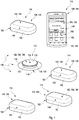
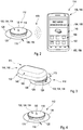
- the at least one further module may comprise one or more of the following further modules: the at least one portable data management device; at least one data transmission module; the at least one data reader module; the at least one alarm module; the at least one dedicated recharging module.
- the at least one further module may comprise at least one portable data management device, wherein the portable data management device is adapted to directly or indirectly receive the measurement data and to at least partially display data on at least one display.
- the at least one data management device may comprise a portable computer, such as a smartphone, a palmtop computer or any other portable computing device.
- the data management device may be adapted to bring the demand for recharging the rechargeable energy storage device to a user's attention, such as in one or more of a visual fashion, an acoustic fashion or a vibrational fashion.
- the data management device may be adapted to provide at least one of a visual indication, such as a display of an appropriate message, and/or an acoustic indication, such as a warning sound or a voice message, and/or a vibrational indication, such as a vibrational alarm, to a user, in order to indicate to the user that a recharging of the rechargeable energy storage device is required.
- a visual indication such as a display of an appropriate message
- an acoustic indication such as a warning sound or a voice message
- a vibrational indication such as a vibrational alarm
- the data management device may be adapted to indicate to a user at least one way of recharging the rechargeable energy storage device.
- the indication may take place in a verbal fashion and/or by using one or more pictograms.
- the data management device may be adapted to indicate to the user that at least one recharging module has to be brought into at least one recharging position with respect to the sensor module.
- a "recharging module” generally may refer to at least one module of the kit which is adapted for recharging the at least one rechargeable energy storage device.
- the at least one recharging module may be or may comprise one or more of the above-mentioned modules, such as the at least one data management device, the at least one data transmission module, the data reader module or the alarm module.
- the at least one recharging module may be or may comprise at least one dedicated recharging module, i.e. at least one module the sole purpose of which or the main purpose of which is the recharging of the at least one rechargeable energy storage device.
- the at least one dedicated recharging module may be part of the at least one further module.
- the at least one further module may comprise at least one data reader module adapted to receive measurement data transmitted by the sensor module via wireless near-field communication.
- the data reader module may comprise at least one data storage device and may be adapted to store the measurement data.
- the term “data reader module” generally refers to a unit which may be handled as a unitary element and which is adapted to store the measurement data.
- the data reader module may comprise at least one near-field communication device.
- a near-field communication device according to one or more of the above-mentioned standards may be used.
- the near-field communication device of the data reader module may be an active device, whereas the wireless near-field communication device of the control device of the sensor module may be a passive communication device.
- the near-field communication device of the data reader module preferably may comprise at least one antenna, such as at least one RFID antenna.
- the data storage device may be an arbitrary storage device adapted to store the measurement data.
- a volatile and/or non-volatile data storage device may be used.
- the storage device also referred to as a memory device or a memory element, may comprise one or more storage chips and/or other types of memory devices, wherein both volatile and non-volatile memory devices may be employed.
- the at least one further module may, additionally or alternatively, comprise at least one data transmission module adapted to receive measurement data transmitted by the sensor module via wireless near-field communication.
- the data transmission module may comprise at least one wireless far-field communication device, wherein the wireless far-field communication device is adapted to transmit at least part of the measurement data to an external device via wireless far-field communication.
- the kit further comprises at least one data transmission module adapted to receive measurement data transmitted by the sensor module via wireless near-field communication.
- the data transmission module comprises at least one wireless far-field communication device, wherein the wireless far-field communication device is adapted to transmit at least part of the measurement data to an external device via wireless far-field communication.
- the term “data transmission module” generally refers to an arbitrary unit which may be handled as a unitary element which is adapted to receive the measurement data via wireless near-field communication from the sensor module and which is adapted to transmit at least part of the measurement data to an external device via wireless far-field communication.
- the data transmission module may comprise at least one wireless near-field communication device adapted to communicate with the wireless near-field communication device of the control device of the sensor module.
- the near-field communication device may be an active near-field communication device, whereas the near-field communication device of the control device of the sensor module may be a passive communication device.
- other options are possible, such as active communication devices in both elements.
- the term “wireless far-field communication” generally refers to a wireless communication adapted to transmit data over long distances, such as distances of more than 10 cm.
- the wireless far-field communication may be an arbitrary long-range communication using electromagnetic waves in the radio frequency range, i.e. may be a radio communication.
- the wireless far-field communication device of the data transmission module may comprise at least one radio module, having at least one radio antenna, for transmitting the measurement data via radio transmission to the at least one external device.
- the term "external device" may be an arbitrary device independent from the data transmission module and the sensor module which is adapted to receive the measurement data via wireless far-field communication.
- the at least one external device may be part of the kit or may be independent from the kit.
- the at least one external device may be a portable device having the capability of communicating via wireless far-field communication, such as a hand-held computer and/or a smartphone.
- the above-mentioned data management device itself may be the external device or may form part of the external device.
- the at least one optional external device may be another device, independent from the components of the kit.
- the external device specifically may be the data management device, such that the data may be transmitted via near-field communication from the sensor module to the data transmission device and, thereafter, from the data transmission device to the data management device via far-field communication. Other embodiments are feasible.
- the at least one further module may, additionally or alternatively, comprise at least one alarm module adapted to receive data transmitted by the sensor module via wireless near-field communication.
- the data transmitted by the sensor module may contain one or both of measurement data or alarm instructions.
- the alarm module may be adapted to generate at least one alarm signal in response to the data transmitted by the sensor module.
- the alarm module may comprise at least one wireless near-field communication device, preferably an active near-field communication device, which may communicate with the near-field communication device of the control device of the sensor element.
- the wireless near-field communication device may comprise at least one antenna.
- the data transmitted by the sensor module may contain alarm instructions.
- the alarm module may be a passive alarm module which simply is adapted for generating an alarm signal in response to alarm instructions received by the sensor module.
- the sensor module may be adapted to determine whether at least one alarm condition is fulfilled, such as in case one or more thresholds of analyte concentration are exceeded, and, if this is the case, may transmit alarm instructions to the alarm module.
- the alarm module may generate an alarm signal in response to these alarm instructions.
- the alarm module may provide, at least partially or to a certain extent, an intelligence of its own, such as by providing one or more processors or other types of data processing devices.
- the data transmitted by the sensor module may contain measurement data.
- the alarm module may be adapted to evaluate the measurement data and to determine whether at least one alarm condition is fulfilled and to provide at least one alarm signal in case the at least one alarm condition is fulfilled.
- the alarm module may comprise at least one data processing device, such as at least one processor and/or microcontroller, adapted to perform at least one evaluation algorithm, wherein the evaluation algorithm is adapted to evaluate the measurement data received by the sensor module and to determine whether the alarm condition is fulfilled or not.
- the at least one alarm condition may comprise at least one comparison with one or more threshold levels, wherein, as an example, an alarm condition may be fulfilled in case a specific threshold level is reached and/or exceeded.
- an alarm condition may be fulfilled in case a maximum tolerable blood glucose level is exceeded.
- the alarm module may be flexible with regard to evaluating the measurement data.
- the alarm module may be a programmable alarm module.
- a user may select and/or adjust one or more thresholds to be used in the alarm condition, such as one or more thresholds for analyte concentrations.
- the alarm module may comprise one or more wireless and/or wire-bound interfaces, such as one or more interfaces adapted to be connected to a personal computer, a smartphone or another type of controller. Via one or more of these interfaces, a programming of the alarm module may be feasible.
- the at least one alarm signal may be generated by at least one alarm device.
- the at least one alarm signal preferably may be selected from the group consisting of an acoustic alarm signal, an optical alarm signal and a vibrational alarm signal.
- other types of alarm signals may be generated, such as alarm signals transmitted via wireless or wire-bound data transmission to at least one external device, such as to at least one medical computer.
- the alarm module preferably may comprise at least one data evaluation device, also referred to as a data processing element.
- the at least one data processing element may have a software code stored therein, with program means for subjecting the measurement data to the at least one alarm condition.
- the alarm module simply may be a passive alarm module adapted for receiving one or more alarm instructions from the sensor module and to provide an alarm signal in response to this at least one alarm instruction.
- the alarm signal preferably may be selected from the group consisting of an acoustic alarm signal, an optical alarm signal and a vibrational alarm signal.
- other types of alarm signals may be generated, such as one or more electronic alarm signals, e.g. alarm signals transmitted via wire-bound and/or wireless signal transmission, such as radio-transmission, to an external device, such as an external computer and/or a smartphone.
- the alarm signal may be an alarm signal which may be recognized by a human user, such as healthcare personal or the user of the kit, and/or an electronic alarm signal which may be recognized as such by a machine.
- the sensor module may comprise a sensor module mechanical interface for reversibly coupling the sensor module to the at least one further module.
- the term "sensor module mechanical interface” generally refers to an arbitrary element or a combination of elements of the sensor module which is adapted to interact with at least one mechanical interface of a further module in order to generate a mechanical connection between the sensor module and the other element.
- the sensor module mechanical interface may comprise an arbitrary type of element or combination of elements which may be used for coupling to the further module, such as one or more elements selected from the group consisting of: a protrusion, a rim, a hook, a depression, a groove. Other types of connection elements may be used additionally or alternatively.
- the at least one further module may comprise at least one corresponding mechanical interface adapted to reversibly engage the sensor module, such as to the optional sensor module mechanical interface, thereby generating a fixed spatial relationship between the sensor module and the at least one further module.
- the at least one further module simply may be brought into close proximity with the at least one sensor module in order to enable a near-field communication between the sensor module and the at least one further module.
- the at least one further module may comprise at least one dedicated recharging module adapted to recharge the rechargeable energy storage device.
- the at least one dedicated recharging module may comprise at least one rechargeable energy storage.
- the at least one rechargeable energy storage may be or may comprise an electrical energy storage, such as one or more of a battery, an accumulator, a capacitor or any other type of electrical energy storage.
- electrical energy storage of the dedicated recharging module may be rechargeable, too.
- the electrical energy storage of the dedicated recharging module may have a capacity of at least 0.1 A ⁇ h, at least 0.3 A ⁇ h, or at least 0.5 A ⁇ h.
- the electrical energy storage of the dedicated recharging module may have a capacity of 0.1 A ⁇ h to 2.0 A ⁇ h, such as 0.3 A ⁇ h to 1.0 A ⁇ h.
- the at least one further module may comprise at least two further modules, comprising:
- the configuration of the kit may be adapted to the actual needs of the measurement situation.
- the weight and the volume of the sensor module may be kept at a low level.
- the sensor module may have a volume below 7 cm 3 , more preferably a volume below 5 cm 3 , below 2.5 cm 3 , or even below 2 cm 3 or below 1.5 cm 3 .
- the sensor module and, more preferably, the control device of the sensor module may be embodied such that no voluminous components are present, such as voluminous wireless far-field communication components and/or voluminous data memories.
- the sensor module may be embodied without any wire-bound data interfaces, such as without any mechanical plugs.
- the sensor module may be embodied as a cheap, small, low-level component which simply may be adapted to acquire measurement data and transmit the measurement data via wireless near-field communication. Still, despite the fact that the sensor module may be kept at a low resource level and, thus, at a low level with regard to weight and volume, the kit may provide a full functionality of modern analytical systems, such as by providing the capability of far-field data transmission to data handling devices such as one or more computers for evaluating the measurement data. Further, the data reader module may be used for data storage and/or data transfer, in the fashion of modern memory sticks, such as USB memory sticks.
- the at least one further module specifically may comprise at least one portable data management device.
- the portable data management device may be adapted to directly or indirectly receive the measurement data and to at least partially display the measurement data.
- the term "at least partially display” generally refers to the fact that one or more of the full measurement data, a part thereof or data or information derived from the measurement data are displayed by using at least one display device, such as a matrix display.
- measurement curves derived from the measurement data may be displayed on a screen, such as an LCD screen or any other type of display device.
- the portable data management device may further be adapted to perform at least one data evaluation algorithm.
- the portable data management device may further be adapted to apply the at least one data evaluation algorithm on the measurement data or a part thereof, such as in order to derive at least one evaluation result.
- an analyte concentration, mean values, a health condition or other types of evaluation results may be derived by using the evaluation algorithm.
- the data management device may simply be a display device adapted for displaying data, only, whereas the sensor module and/or the data transmission module may provide the capability of data evaluation.
- the data management device may provide an intelligence of its own, such as by providing one or more data processing devices adapted to apply the at least one data evaluation algorithm on the measurement data.
- the term "portable” generally refers to the fact that the data management device may be carried by a user, such as by hand.
- the data management device may be a hand-held data management device.
- the data management device may have a weight of less than 1 kg, preferably a weight of less than 500 g and, more preferably, a weight of less than 300 g.
- the portable data management device may have a volume of preferably less than 1000 cm 3 , more preferably of less than 120 cm 3 or even less than 60 cm 3 .
- the term "data management device”, as used herein, refers to a device adapted to handle measurement data, such as by storing the measurement data and/or subjecting the measurement data to at least one data evaluation algorithm.
- the data management device may have at least one algorithm for displaying the measurement data, such as by displaying the measurement data on a display device, thereby displaying one or more measurement curves.
- averaging algorithms may be applied to the measurement data and/or one or more algorithms adapted to give medical advice to the user.
- the portable data management device may comprise one or more databases, such as for storing and/or comparing measurement data.
- the portable data management device may be adapted to directly or indirectly receive the measurement data.
- directly receiving the measurement data refers to the option that the portable data management device directly receives the measurement data from the sensor module, such as by wireless near-field communication.
- indirectly receiving the measurement data generally refers to the option that at least one intermediate device may be used for transmitting the measurement data fully or in part to the portable data measurement device.
- the at least one data transmission module may be used for transmitting the measurement data fully or in part to the portable data management device via wireless far-field communication.
- the data management device may further be adapted to perform one or more additional actions.
- the data management device may be adapted to initiate one or more further actions, such as to automatically shut off a medication pump, specifically an insulin pump, in response to the measurement data.
- the data evaluation algorithm may be adapted to determine whether one or more conditions are fulfilled, on the basis of the measurement data, and, in response to this determination, may initiate one or more actions such as shutting off the medication pump.
- the data management device may be adapted to send data and/or instructions to one or more other devices.
- the data management device may be adapted to communicate with the sensor module.
- the data management device may be adapted to transmit data to the sensor module, preferably via near-field communication.
- the data management device may be adapted to transmit calibration data to the sensor module.
- the data management device may be adapted to transmit specific alarm conditions and/or alarm adjustments which may individually be adjustable by a user.
- the portable data management device may comprise at least one device selected from the group consisting of: a portable computer; a smartphone; a watch; a medication pump, such as an insulin pump or a part thereof, such as a medication pump controller; a hand-held device for determining a concentration of the analyte in a body fluid.
- the portable data management device comprises a hand-held device for determining a concentration of the analyte in a body fluid
- the hand-held device generally may comprise an arbitrary meter for determining the analyte concentration.
- the hand-held device may be adapted to use at least one test element having at least one test field, preferably a test strip or a test tape, wherein a sample of the body fluid may be applicable to the test field.
- the hand-held device may be a spot meter adapted to perform an in vitro analysis of the body fluid.
- the hand-held device may be a hand-held glucose monitoring device using one or more test strips or one or more test tapes, wherein a sample of the body fluid, such as a droplet of blood and/or interstitial fluid, may be applied to the test strip or test tape, in order to determine the concentration of the analyte in the body fluid, such as the blood glucose concentration.
- the hand-held device generally may comprise a commercially available blood glucose meter. Additionally or alternatively, other types of hand-held devices for determining the analyte concentration may be used.
- the data management device further may comprise one or more user interfaces allowing for a user to insert commands.
- the data management device may comprise one or more keys for inserting data and/or commands.
- the data management device additionally or alternatively may comprise at least one data processing element adapted to apply at least one data processing algorithm to the measurement data.
- the data processing element may be adapted to apply at least one averaging algorithm and/or at least one evaluation algorithm to the measurement data, wherein, as an example, one or more types of information may be derived from the measurement data, such as information regarding the measurement data exceeding certain levels of the analyte concentration.
- the data management device may comprise one or more databases for storing the measurement data.
- the measurement device may be adapted to receive measurement data from the data transmission module via wireless far-field communication.
- the data management device may comprise one or more far-field communication components, such as one or more radio components. Additionally or alternatively, the data management device may be adapted to receive measurement data from the data transmission module via other ways of communication.
- the data management device further may be adapted to receive measurement data directly from the sensor module via wireless near-field communication.
- the data management device may comprise one or more wireless near-field communication devices.
- many hand-held devices such as modern smartphones comprise near-field communication devices, such as for reading RFID tags.
- the data management device may comprise one or more RFID readers to receive measurement data via RFID communication from the sensor module.
- the data management device may further comprise at least one display element adapted to display a plurality of measurement data.
- the display element may comprise an active or passive display, such as a matrix display.
- the display element may be adapted to display measurement curves comprising a plurality of measurement data.
- the measurement device may be adapted to display a time development of the measurement data.
- the sensor module preferably may be a disposable sensor module.
- the sensor module may be embodied such that the sensor module may be disposed as an entity.
- the sensor module may comprise a housing, which, preferably, may not be opened in a non-destructive fashion.
- the housing of the sensor module is a unitary piece containing all components of the control device, including the data collection device and the wireless near-field communication device as cheap, single-use components.
- the kit according to the present invention may comprise a plurality of exchangeable sensor modules.
- the at least one further module may be embodied as one or more reusable units.
- the at least one further module and may comprise at least one rechargeable and/or exchangeable energy storage, such as at least one rechargeable and/or exchangeable battery and/or a rechargeable accumulator.
- the at least one further module comprises a housing which may be opened in a non-destructive way, in order to exchange the exchangeable energy storage.
- the further module may comprise a recharging device, which may be embodied as a wire-bound recharging device such as a plug and/or as a wireless charging device, such as an inductive recharging device.
- a method for determining a concentration of at least one analyte in a body fluid of a user comprises the steps described hereinafter.
- the method steps may be performed in the given order or in a different order. Further, one or more or even all of the method steps may be performed once or more than once or even repeatedly.
- the method may further comprise additional method steps which are not listed.
- the method comprises the use of one or both of the sensor module to the present invention, such as according to one or more of the embodiments disclosed above or disclosed in further detail below, and/or of the kit according to the present invention, such as according to one or more of the embodiments disclosed above or disclosed in further detail below.
- the method may further comprise transmitting at least one demand for recharging the rechargeable energy storage device of the sensor module via the near-field communication device of the sensor module.
- the method may further comprise at least one step of fully or partially recharging the at least one rechargeable energy storage device of the sensor module with electrical energy provided externally to the sensor module.
- the sensor module, the kit and the method according to the present invention provide a large number of advantages over known devices for determining an analyte concentration, such as continuous monitoring glucose sensors.
- the sensor module may be embodied as a very small module, having the analyte sensor and, as an example, a small, button-like control device on the skin surface of the user.
- the control device as an example, may be mounted to the skin of the user by using an adhesive, such as an adhesive tape. Still, by using the flexible energy concept as proposed within the present invention, a sufficient time for operation and storage of the control device may be provided, due to the possibility of recharging the rechargeable energy storage device.
- the duration of operation of the sensor module may be limited by a test chemical or sensor chemical of the sensor element rather than by the energy content of the rechargeable energy storage device.
- a data transfer rate and a mode of data transfer may be chosen according to the requirements of the kit and are not a limiting factor for the duration of operation of the sensor module any longer, also due to the possibility of recharging the at least one rechargeable energy storage device.
- the kit may be embodied to perform a mode of reading on demand.
- a data transfer of measurement data from the sensor module, directly or via the at least one data transmission module, to the data management device may take place on demand, such as initiated by the user.
- This mode generally requires a lower energy supply as compared to a mode of online monitoring, in which the sensor module permanently sends measurement data.
- the sensor module not necessarily has to be capable of storing an energy content for a storage and a period of operation, such as for seven days.
- the at least one rechargeable energy storage device may contain a lower energy content, and may be recharged on demand. Consequently, the at least one rechargeable energy storage device may be chosen at a smaller volume, and, consequently, the at least one sensor module, which may be embodied as a disposable sensor module, may be constructed smaller and at lower cost. Energy reserves and an over-dimensioning are not required any longer.
- the energy management concept specifically may be managed by the data management device.
- the data management device which may also be referred to as a "controller” obtains information on a status of charge of the at least one rechargeable energy storage device of the sensor module. This information may be transmitted in one step or a plurality of steps, i.e. directly or via one or intermediate steps, from the sensor module to the data management device.
- a near-field communication may take place from the sensor module to the at least one data transmission module, and, therefrom, to the at least one data management device.
- a direct near-field communication may take place between the sensor module and the data management device.
- the data management device may provide appropriate commands for recharging the at least one rechargeable energy storage device of the sensor module.
- appropriate commands for recharging may be transmitted to one or more recharging modules, which may be one or more dedicated recharging modules and/or which may be one or more modules which actually are mainly adapted for performing different purposes.
- the at least one further module as mentioned above may contain a dedicated recharging module having a rechargeable energy storage, such as a rechargeable accumulator.
- the dedicated recharging module may be coupled to the at least one sensor module for recharging the at least one rechargeable energy storage device of the sensor module.
- the coupling may take place via at least one mechanical interface and/or via simply bringing the at least one dedicated recharging module into close proximity with the sensor module.
- a successful finishing of the recharging may be signalized to the user.
- a remaining energy content of the dedicated recharging module may be signalized to the user, such as via one or more of a visual indication, an acoustic indication or a vibrational indication.
- the recharging module may make use of a data transmission module, such as a radio transmission module.
- This data transmission module may be used as a recharging module and may be used for recharging the at least one rechargeable energy storage device of the sensor module.
- the data transmission module may be coupled to the at least one sensor module or may simply be brought into close proximity with the sensor module.
- the data transmission module may fully or partially energize the sensor module, in order to save energy during recharging of the at least one rechargeable energy storage device and in order to provide energy for operation of the sensor module during recharging.
- the at least one data management device itself may be used as a recharging module.
- the data management device with its energy storage, may be used for recharging the rechargeable energy storage device of the sensor module.
- the data management device may either be coupled to the sensor module or may be brought into close proximity with the sensor module during recharging.
- the near-field communication may be used.
- the sensor module contains the at least one wireless near-field communication device. This at least one wireless near-field communication device itself may also be used for recharging the rechargeable energy storage device of the sensor module.
- the recharging module may inductively transfer energy to the sensor module.
- one or more of an oscillator, a rectifier or an inverter may be used for transforming a direct current within the recharging module into an alternating current, for inductively recharging the rechargeable energy storage device of the sensor module.
- a rectification from an alternating current into a direct current may take place. This energizing concept is generally known from electric toothbrushes.
- a capacitive energy transfer may take place.
- the recharging module may be adapted for capacitively coupling energy into the sensor module.
- the energy requirements for maintaining the functionality of the control device of the sensor module generally are rather low.
- the present energy concept may include an emergency energizing.
- an emergency power supply may be provided within the sensor module.
- a piezo-electric charge generation within the sensor module may take place, initiated by the patient.
- the patient may induce pressure and/or movement in one or more piezo-electric elements, such as by hand.
- the piezo-electric energy may be used for at least partially recharging the rechargeable energy storage device.
- the at least one emergency power supply may be based on Eddie currents.
- the patient preferably manually, may induce a mechanical movement of one or more parts of the sensor module, such as one or more parts containing a magnet. By inducing these movements, Eddie currents and, thereby, electrical charges may be generated and may be used for at least partially recharging the rechargeable energy storage device of the sensor module.
- the energy concept according to the present invention generally increases the flexibility of the sensor module and the overall kit for analyte monitoring.
- the varying time of the sensor module as well as the measuring modi generally may be embodied independent from the actual energy source of the sensor module.
- the sensor module which preferably may be embodied as a "button sensor", having a button-shaped control device and a sensor element protruding therefrom, may communicate its charging status, directly or indirectly, via near-field communication to the data management device.
- the data management device may send an appropriate recharging command to at least one recharging module, if the energy of the rechargeable energy storage device of the sensor module turns out to be low.
- various concepts for embodiments of the recharging module may be feasible.
- the at least one data management device and/or the at least one recharging module may be considered as "at least one further module" which generally receives information regarding a status of charge of the at least one rechargeable energy storage device of the sensor module and may take appropriate measures for recharging the rechargeable energy storage device, with the user's help or automatically.
- the at least one rechargeable energy storage device may contain printed batteries and/or an additional module with printed batteries.
- the emergency power supply may make use of one or more energy harvesting concepts, as generally known in the art.
- movement, temperature, pressure or other types of external influences may be used and may be transformed into energy usable by the emergency power supply.
- the at least one sensor module of the kit is adapted for communicating with at least one further module of the kit, via near-field communication.
- the at least one further module may comprise one or more of the following:
- one or more of the data management device, the data transmission module, the data reader module or the alarm module may also be used as recharging modules, since, generally, all of these modules will imply one or more energy storage functions, capable of sharing energy with the rechargeable energy storage device of the sensor module.
- this dedicated recharging module may contain a rechargeable accumulator which may be coupled, preferably wirelessly, to the sensor module, in order to recharge the at least one rechargeable energy storage device of the sensor module.
- the at least one data transmission module which specifically may be a radio module, may be used as a recharging module.
- this data transmission module typically provides a rechargeable accumulator and may be used for reloading or even substituting the energy storage device of the sensor module.
- the data management device may be adapted to recharge the sensor module with its rechargeable energy storage, such as via NFC or RF communication.
- kit 110 for determining a concentration of at least one analyte in a body fluid.
- the kit comprises at least one sensor module 112 and at least one further module 114.
- five optional types of further modules 114 are depicted which will be explained in further detail below. It shall be noted that, however, an arbitrary combination of the at least one sensor module 112 and one or more of the further modules 114 as depicted in Figure 1 is also feasible.
- the sensor module 112 comprises at least one sensor element 116 adapted to be at least partially implanted into a body tissue of the user.
- the sensor element 116 may be or may comprise at least one electrochemical sensor element, having at least one working electrode and at least one counter electrode, for electrochemically determining the concentration of the at least one analyte in the body fluid.
- the sensor element 116 may comprise one or more biocompatible coatings, such as one or more biocompatible membranes, in order to enhance biocompatibility of the implanted sensor element 116.
- the sensor element 116 is connected to at least one control device 118 which, for example, may be encapsulated by a housing 120.
- the control device 118 may comprise at least one data collection device 122 and at least one wireless near-field communication device 124.
- the data collection device 122 may comprise one or more data storage devices, such as one or more volatile and/or non-volatile data collection devices.
- the at least one wireless near-field communication device 124 may comprise one or more electronic components for near-field communication, as the skilled person will know.
- the sensor module 112 may further comprise at least one self-adhesive patch 126 adapted to mount the sensor module 112 to a skin surface of the user.
- the sensor module 112 may further comprise a sensor module mechanical interface 128.
- the sensor module mechanical interface 128 may comprise a circumferential protruding rim 130 which may be part of the housing 120, as depicted in Figure 1 , or which may be attached to the housing 120. It shall be noted, however, that the sensor module mechanical interface 128 is an optional part and that the at least one further module 114 may as well simply be held in close proximity to the sensor module 112 for near-field communication and/or for recharging.
- the sensor module 112, as depicted in Figure 1 may have a rotational symmetry and, preferably, may have a volume of less than 2 cm 3 .
- the housing 120 may have a central opening 132 through which an insertion tool for inserting the sensor element 116 into the body tissue may penetrate the housing 120.
- the sensor module 112 further comprises at least one rechargeable energy storage device 134.
- the at least one rechargeable energy storage device 134 may be adapted for supplying electrical energy to the control device 118 of the sensor module 112.
- the at least one rechargeable energy storage device 134 may be or may comprise at least one rechargeable battery and/or at least one rechargeable accumulator and/or at least one capacitor or supercapacitor.
- the at least one sensor module 112 may be adapted for wirelessly recharging the rechargeable energy storage device 134, such as by one or more of an inductive coupling, a capacitive coupling, magnetic coupling or electromagnetic radiation.
- the kit 110 further comprises the at least one further module 114.
- the at least one further module 114 may comprise one or more of a data management device 136, a data reader module 138, a data transmission module 140, an alarm module 142 or a dedicated recharging module 144.
- the main or even sole purpose of the dedicated recharging module 144 is a recharging of the rechargeable energy storage device 134 of the sensor module 112.
- one or more or even all of the other further modules 114 may act as recharging modules 146, since each of these further modules 114 may comprise one or more energy storage devices 148 which may provide energy, preferably electrical energy, to the sensor module 112 and the rechargeable energy storage device 134 of the sensor module 112.
- the further modules 114 may all optionally have a more or less similar geometric shape. Still, the further modules 114 may also be distinct, such as in terms of color and/or labeling or marking.
- the further modules 114 may, individually, have a mechanical interface 150 for coupling the respective further module 114 to the sensor module mechanical interface 128. Alternatively, however, as depicted in Figure 3 below or as explained above, the further modules 114 as well may remain in an uncoupled state and simply may be brought into close proximity with the sensor module 112.
- the data reader module 138 may be adapted to receive measurement data transmitted by the sensor module 112 via wireless near-field communication.
- the data reader module 138 may comprise a wireless near-field communication device 152.
- the data transmission module 140 and, optionally, the alarm module 142 each may comprise one or more wireless near-field communication devices 152.
- the data reader module 138 further comprises at least one data storage device 154 and may be adapted to store measurement data transmitted by the sensor module 112 via wireless near-field communication.
- the at least one data transmission module 140 may comprise at least one wireless far-field communication device 156, such as at least one radio module.
- the wireless far-field communication device 156 may be adapted to transmit at least part of the measurement data to an external device via wireless far-field communication.
- a wireless near-field communication between the sensor module 112 and the data transmission module 140 may take place, and the data transmission module may be adapted to transmit the measurement data, fully or partially, via wireless far-field communication to at least one external device, such as to the at least one data management device 136 and/or to at least one further device, such as a computer, a computer network or a mobile device.
- the alarm module 142 may comprise at least one data processing element 158 and may be adapted to evaluate the measurement data, in order to determine whether at least one alarm condition is fulfilled. Further, the alarm module 142 may be adapted to provide at least one alarm signal in case the at least one alarm condition is fulfilled.
- the alarm module 142 may comprise at least one alarm signal generator 160, such as an alarm signal generator 160 selected from the group consisting of an acoustic alarm signal generator, an optical alarm signal generator and a vibrational alarm signal generator.
- the alarm module 142 may be adapted to vibrate and/or give an acoustic alarm signal and/or an optical alarm signal, such as an alarm sound and/or by providing repeated flashings of light and/or by changing an illumination state.
- the further modules 114 may be designed as reusable components and, preferably, each may have a housing 162.
- the housings 162 may provide the option of being opened, in order to exchange a battery and/or another type of energy storage device 148.
- other ways of recharging and/or exchanging the energy storage devices 148 of the further modules 114 may be provided, such as in a wire-bound fashion and/or in a wireless fashion, such as by using a docking station or the like.
- the kit 110 may be embodied such that the at least one further module 114 comprises the at least one data management device 136, preferably at least one portable data management device 136.
- the data management device 136 preferably may be a hand-held device, such as a hand-held computer and/or a hand-held communication device, such as a smartphone.
- the data management device 136 may, in one option, directly communicate with the sensor module 112 via wireless near-field communication, in order to receive measurement data. Additionally or alternatively, however, the data management device 136 may communicate with the data transmission module 140 via wireless far-field communication, in order to receive the measurement data from the sensor module 112 indirectly, via the data transmission module 140.
- the data management device 136 may comprise at least one user interface 164, allowing for a user to insert commands and/or information. As indicated in Figure 1 , the user interface 164 may comprise, for example, a touchscreen. The data management device 136 may further, additionally or alternatively, comprise at least one display element 166, for displaying data and/or measurement results and/or additional information, such as information regarding a recharging procedure of the sensor module 112, as will be outlined in further detail below with reference to Figure 2 .
- the data management device 136 may comprise at least one data processing element 168, such as at least one processor, adapted to apply at least one data processing algorithm to the measurement data.
- the data management device 136 may further comprise at least one data storage device and/or a memory, such as at least one database, for storing the measurement data.
- the data management device 136 may be adapted to apply at least one data processing algorithm to the measurement data.
- This data processing algorithm may imply a visualization of measurement data, such as a graphical display of measurement curves.
- one or more items of additional information may be generated by evaluating the measurement data, such as by comparing the measurement data with one or more threshold values, in order to generate information on a medical status of the user.
- the data management device 136 may optionally comprise at least one wireless near-field communication device 152.
- the data management device 136 may further comprise at least one wireless far-field communication device 156, as indicated in Figure 1 .
- the sensor module 112 may be operated such that the sensor element 116 is at least partially implanted into a body tissue of the user.
- the sensor module 112 may communicate with one or more of the further modules 114 via wireless near-field communication, in order to transmit measurement data.
- measurement data may be transferred to the data reader module 138 via wireless near-field communication.
- the data reader module 138 may be adapted to store the measurement data in the data storage device 154.
- the data reader module 138 may fully or partially transfer the measurement data to another device, such as to the at least one data management device 136, and/or to another computer, such as a personal computer and/or a smartphone.
- the transfer may take place wirelessly and/or in a wire-bound fashion, such as via one or more interfaces not depicted in Figure 1 .
- the data reader module 138 may comprise a USB interface and/or another type of plug.
- a wireless transfer may take place, such as data transfer via infrared data transmission, Bluetooth or other types of wireless data transmission.
- the data reader module 138 may be used in the same fashion as a USB data stick.
- the user may collect measurement data on a regular basis, by using the data reader module 138, and may transfer the measurement data to a medical supervisor, such as a doctor, by simply carrying the data reader module to the medical supervisor's office.
- the data reader module 132 may provide sufficient storage capability for storing measurement data over an elongated time period, such as over one week or several weeks.
- the sensor module 112 may further transfer measurement data via wireless near-field communication to the at least one data transmission module 140, such as in a state in which the data transmission module 140 is in close proximity with the sensor module 112 and/or in which the data transmission module 140 is coupled to the sensor module 112.
- the data transmission module 140 thereafter, may transfer the measurement data, by using its wireless far-field communication device 156, to one or more external devices or other devices, such as to the data management device 136 and/or to another device, such as a computer, a computer network or a mobile device.
- the wireless far-field communication device 156 may be designed as a radio transmitter, a radio receiver and/or a radio transceiver.
- the sensor module 112 comprises the at least one rechargeable energy storage device 134 which allows for operation of the control device 118 over a specific time period.
- the control device may further be adapted to transmit, via the near-field communication device 124, at least one demand for recharging the rechargeable energy storage device 134.
- the demand which may also be referred to as a request for recharging and/or a status report on a status of charge of the rechargeable energy storage device 134, may be transferred to one or more of the further modules 114.
- the control device 118 may be adapted to transmit the at least one demand for recharging the rechargeable energy storage device 134 directly or indirectly to the data management device 136.
- the near-field communication 170 may take place directly between the sensor module 112 and the data management device 136. Additionally or alternatively, at least one intermediate station of transmission may be used.
- the data transmission module 140 may be used for receiving the demand for recharging the rechargeable energy storage device 134 and may transmit the demand to the data management device 136, by near-field communication and/or by other means of communication, such as wireless far-field communication.
- the request or demand for recharging the rechargeable energy storage device 134 is transmitted to the data management device 136.
- the data management device 136 may be adapted to initiate a recharging process.
- a processor of the data management device 136 may be adapted to evaluate the demand for recharging the rechargeable energy storage device 134.
- a processor of the data management device 136 may be adapted to compare at least one status information regarding a status of charge of the rechargeable energy storage device 134 with at least one threshold value, in order to recognize a need for recharging the rechargeable energy storage device 134.
- the information transmitted by the sensor module 112 may directly contain the information that the rechargeable energy storage device 134 has to be recharged.
- the data management device 136 may be adapted, in case a need for recharging is detected, to take appropriate measures in order to recharge the rechargeable energy storage device 134.
- the display element 166 may indicate visual indications indicating the need for recharging the rechargeable energy storage device 134.
- verbal messages may be displayed.
- visual messages may be displayed which indicate at least one way of recharging the rechargeable energy storage device, such as by bringing one or more recharging modules 146 in a recharging position with respect to the sensor module 112. Both options are depicted symbolically in Figure 2 .
- a recharging procedure initiated by the data management device 136, is depicted.
- one or more recharging modules 146 may be brought into close proximity with the sensor module 112.
- the at least one recharging module 146 may simply be brought into close proximity with the sensor module 112 and/or may even be coupled to the sensor module 112, such as by coupling the mechanical interface 150 to the sensor module mechanical interface 128.
- the recharging module 146 may be the dedicated recharging module 144 and/or another type of further module 114.
- the data reader module 138, the data transmission module 140 or even the alarm module 142 may be used as recharging modules.
- the data reader module 138 itself may be used as a recharging module 146 for recharging the rechargeable energy storage device 134 of the sensor module 112.
- energy may be transferred from the energy storage device 148 of the recharging module 146 into the rechargeable energy storage device 134 of the sensor module 112.
- the energy transfer in Figure 3 , is symbolically depicted by reference number 172.
- the recharging procedure and the energy transfer 172 may take place in a wireless fashion.
- the recharging and the energy transfer 172 may take place by one or more of an inductive coupling, a capacitive coupling, the near-field communication device 124 or any other type of electromagnetic coupling or electromagnetic radiation.
- the energy transfer 172 may take place by using one or more coils within the recharging module 146 and the sensor module 112, generating an inductive coupling.
- the recharging module 146 and the sensor module 112 each may contain one or more capacitors which may be coupled in a capacitive way, in order to capacitively transfer energy from the recharging module 146 to the sensor module 112.
- other types of transmitters, receivers or transceivers may be used for wirelessly transferring energy from the recharging module 146 to the sensor module 112.
- an emergency power supply 174 of the sensor module 112 is symbolically depicted.
- a user may manually recharge the rechargeable energy storage device 134 by using the emergency power supply.
- the emergency power supply 174 as depicted in Figure 4 may comprise one or more buttons or levers on an outer side of the housing 120 of the sensor module 112. The user may manually operate this lever, in order to generate piezo-electric energy which, again, may be used to fully or partially recharge the rechargeable energy storage device 134.
- emergency power supply 174 means of emergency power supply 174 are feasible, such as energy harvesting methods and/or methods inducing Eddie currents in order to recharge the rechargeable energy storage device 134.
Claims (14)
- Module capteur (112) pour déterminer une concentration d'au moins un analyte dans un fluide corporel d'un utilisateur comprenant :a. au moins un élément capteur (116) adapté pour déterminer la concentration de l'analyte, où l'élément capteur (116) est au moins partiellement implantable dans un tissu corporel de l'utilisateur ;b. au moins un dispositif de commande (118) connecté à l'élément capteur (116), où le dispositif de commande (118) comprend au moins un dispositif de collecte de données (122) adapté pour collecter des données de mesure acquises en utilisant l'élément capteur (116),où le dispositif de commande (118) comprend en outre au moins un dispositif de communication sans fil en champ proche (124) adapté pour transmettre des données de mesure, où le dispositif de commande (118) comprend en outre un dispositif de stockage d'énergie rechargeable (134), et où le dispositif de commande (118) est adapté pour transmettre au moins une demande pour recharger le dispositif de stockage d'énergie rechargeable (134) par l'intermédiaire du dispositif de communication en champ proche (124), la demande de recharge comprenant une information indiquant qu'une recharge du dispositif de stockage d'énergie rechargeable (134) est requise pour maintenir un fonctionnement du module capteur,
et où le module capteur (112) comprend en outre au moins une alimentation de secours (174), où l'alimentation de secours (174) est adaptée pour fournir une quantité d'énergie au dispositif de stockage d'énergie rechargeable (134) lorsqu'une recharge ordinaire n'est momentanément pas possible. - Module capteur (112) selon la revendication précédente, dans lequel le dispositif de commande (118) est adapté pour recharger le dispositif de stockage d'énergie rechargeable (134) avec de l'énergie électrique fournie, de manière externe, au module capteur (112).
- Kit (110) pour déterminer une concentration d'au moins un analyte dans un fluide corporel d'un utilisateur, le kit (110) comprenant :- le module capteur (112) selon l'une quelconque des revendications précédentes, et- au moins un autre module (114), dans lequel l'au moins un autre module (114) est adapté pour recevoir l'au moins une demande pour recharger le dispositif de stockage d'énergie rechargeable (134).
- Kit (110) selon la revendication précédente, dans lequel l'au moins un autre module (114) est adapté pour fournir de l'énergie au dispositif de stockage d'énergie rechargeable (134).
- Kit (110) selon la revendication précédente, dans lequel l'au moins un autre module (114) est adapté pour fournir de l'énergie électrique au dispositif de stockage d'énergie rechargeable (134), sans contact.
- Kit (110) selon l'une quelconque des revendications précédentes se référant à un kit (110), dans lequel l'au moins un autre module (114) comprend au moins un dispositif de gestion de données portable (136), où le dispositif de gestion de données portable (136) est adapté pour recevoir directement ou indirectement les données de mesure et pour afficher, au moins partiellement, des données sur au moins un affichage (170).
- Kit (110) selon la revendication précédente, dans lequel le dispositif de gestion de données portable (136) est adapté pour attirer l'attention d'un utilisateur sur la demande de recharge du dispositif de stockage d'énergie rechargeable (134).
- Kit (110) selon l'une quelconque des deux revendications précédentes, dans lequel le dispositif de gestion de données portable (136) est adapté pour indiquer à un utilisateur au moins un moyen pour recharger le dispositif de stockage d'énergie rechargeable (134).
- Kit (110) selon la revendication précédente, dans lequel le dispositif de gestion de données portable (136) est adapté pour indiquer à l'utilisateur qu'au moins un module de recharge (146) doit être amené dans au moins une position de recharge par rapport au module capteur (112).
- Kit (110) selon l'une quelconque des revendications précédentes se référant à un kit (110), dans lequel l'au moins un autre module (114) comprend au moins un module lecteur de données (138) adapté pour recevoir des données de mesure transmises par le module capteur (112) par l'intermédiaire d'une communication sans fil en champ proche, où le module lecteur de données (138) comprend au moins un dispositif de stockage de données (154) et est adapté pour stocker les données de mesure.
- Kit (110) selon l'une quelconque des revendications précédentes se référant à un kit (110), dans lequel l'au moins un autre module (114) comprend au moins un module de transmission de données (140) adapté pour recevoir des données de mesure transmises par le module capteur (112) par l'intermédiaire d'une communication sans fil en champ proche, où le module de transmission de données (140) comprend au moins un dispositif de communication sans fil en champ lointain (156), le dispositif de communication sans fil en champ lointain (156) étant adapté pour transmettre au moins partiellement les données de mesure à un dispositif externe par l'intermédiaire d'une communication sans fil en champ lointain.
- Kit (110) selon l'une quelconque des revendications précédentes se référant à un kit (110), dans lequel l'au moins un autre module (114) comprend au moins un module d'alarme (142) adapté pour recevoir des données transmises par le module capteur (112) par l'intermédiaire d'une communication sans fil en champ proche, où les données transmises par le module capteur (112) contiennent un ou deux éléments parmi des données de mesure ou des instructions d'alarme.
- Kit (110) selon l'une quelconque des revendications précédentes se référant à un kit (110), dans lequel l'au moins un autre module (114) comprend au moins un module de recharge dédié (144) adapté pour recharger le dispositif de stockage d'énergie rechargeable (134).
- Procédé pour déterminer une concentration d'au moins un analyte dans un fluide corporel d'un utilisateur, le procédé comprenant l'utilisation d'un ou des deux dispositifs parmi le module capteur (112) selon l'une quelconque des revendications précédentes se référant à un module capteur (112) ou un kit (110) selon l'une quelconque des revendications précédentes se référant à un kit (110), où le procédé comprend en outre de transmettre au moins une demande pour recharger le dispositif de stockage d'énergie rechargeable (134) du module capteur (112) par l'intermédiaire du dispositif de communication en champ proche (124) du module capteur (112).
Priority Applications (2)
| Application Number | Priority Date | Filing Date | Title |
|---|---|---|---|
| EP15183461.1A EP3138488B1 (fr) | 2015-09-02 | 2015-09-02 | Module de détection et kit de détermination d'une concentration d'analyte |
| US15/249,642 US10424975B2 (en) | 2015-09-02 | 2016-08-29 | Sensor module and kit for determining an analyte concentration |
Applications Claiming Priority (1)
| Application Number | Priority Date | Filing Date | Title |
|---|---|---|---|
| EP15183461.1A EP3138488B1 (fr) | 2015-09-02 | 2015-09-02 | Module de détection et kit de détermination d'une concentration d'analyte |
Publications (2)
| Publication Number | Publication Date |
|---|---|
| EP3138488A1 EP3138488A1 (fr) | 2017-03-08 |
| EP3138488B1 true EP3138488B1 (fr) | 2019-06-05 |
Family
ID=54065196
Family Applications (1)
| Application Number | Title | Priority Date | Filing Date |
|---|---|---|---|
| EP15183461.1A Active EP3138488B1 (fr) | 2015-09-02 | 2015-09-02 | Module de détection et kit de détermination d'une concentration d'analyte |
Country Status (2)
| Country | Link |
|---|---|
| US (1) | US10424975B2 (fr) |
| EP (1) | EP3138488B1 (fr) |
Families Citing this family (11)
| Publication number | Priority date | Publication date | Assignee | Title |
|---|---|---|---|---|
| WO2017069939A1 (fr) * | 2015-10-20 | 2017-04-27 | Carrier Corporation | Surveillance de paramètre biodégradable |
| US10653349B2 (en) * | 2016-10-18 | 2020-05-19 | International Business Machines Corporation | Diagnostic apparatus |
| EP3609404A4 (fr) * | 2017-04-12 | 2020-12-23 | Roche Diabetes Care GmbH | Système médical |
| JP6938685B2 (ja) * | 2017-06-02 | 2021-09-22 | ノースウェスタン ユニヴァーシティNorthwestern University | 表皮試料採取および感知のためのマイクロ流体システム |
| DE102017010150A1 (de) * | 2017-11-02 | 2019-05-02 | Drägerwerk AG & Co. KGaA | Verfahren, Kontrolleinheit, Computerprogrammprodukt sowie System zum Bereitstellen einer Ausfallsicherheit eines medizinischen Überwachungsvorgangs |
| EP3727150A1 (fr) * | 2017-12-18 | 2020-10-28 | Sanofi | Glucomètre nfc contenant une batterie rechargeable pour utilisation indépendante |
| USD967724S1 (en) * | 2020-09-22 | 2022-10-25 | Comcast Cable Communications, Llc | Sensor |
| USD967723S1 (en) * | 2020-09-22 | 2022-10-25 | Comcast Cable Communications, Llc | Sensor |
| USD978697S1 (en) * | 2020-09-22 | 2023-02-21 | Comcast Cable Communications, Llc | Sensor kit |
| USD978696S1 (en) * | 2020-09-22 | 2023-02-21 | Comcast Cable Communications, Llc | Sensor kit |
| TWD217612S (zh) * | 2021-05-11 | 2022-03-11 | 宏碁股份有限公司 | 定位追蹤器 |
Family Cites Families (27)
| Publication number | Priority date | Publication date | Assignee | Title |
|---|---|---|---|---|
| CA2284675C (fr) * | 1997-03-27 | 2012-01-31 | Alfred E. Mann Foundation For Scientific Research | Systeme de dispositifs implantables concu pour surveiller et/ou modifier des parametres corporels |
| US6175752B1 (en) | 1998-04-30 | 2001-01-16 | Therasense, Inc. | Analyte monitoring device and methods of use |
| US6360888B1 (en) | 1999-02-25 | 2002-03-26 | Minimed Inc. | Glucose sensor package system |
| EP1339312B1 (fr) * | 2000-10-10 | 2006-01-04 | Microchips, Inc. | Systemes-reservoirs a micropuce utilisant la transmission sans fil d'energie et de donnees |
| KR20040015344A (ko) | 2001-07-09 | 2004-02-18 | 노보 노르디스크 에이/에스 | 2개의 휴대용 의료장치 사이에서 데이터 정보를 제어하는방법 및 시스템 |
| US8775196B2 (en) * | 2002-01-29 | 2014-07-08 | Baxter International Inc. | System and method for notification and escalation of medical data |
| US20060001551A1 (en) | 2004-06-30 | 2006-01-05 | Ulrich Kraft | Analyte monitoring system with wireless alarm |
| US8280476B2 (en) | 2005-03-29 | 2012-10-02 | Arkal Medical, Inc. | Devices, systems, methods and tools for continuous glucose monitoring |
| US7756561B2 (en) | 2005-09-30 | 2010-07-13 | Abbott Diabetes Care Inc. | Method and apparatus for providing rechargeable power in data monitoring and management systems |
| US7813801B2 (en) * | 2005-12-15 | 2010-10-12 | Cardiac Pacemakers, Inc. | Implantable medical device powered by rechargeable battery |
| US20090171178A1 (en) | 2006-03-31 | 2009-07-02 | Abbott Diabetes Care, Inc. | Method and System for Powering an Electronic Device |
| US8770482B2 (en) | 2006-04-26 | 2014-07-08 | Roche Diagnostics Operations, Inc. | Apparatus and method to administer and manage an intelligent base unit for a handheld medical device |
| US8845530B2 (en) | 2007-01-02 | 2014-09-30 | Isense Corporation | Resposable biosensor assembly and method of sensing |
| US20080167531A1 (en) * | 2007-01-05 | 2008-07-10 | Cardiac Pacemakers, Inc. | System and method to monitor battery status in an implantable medical device |
| EP1972267A1 (fr) | 2007-03-20 | 2008-09-24 | Roche Diagnostics GmbH | Système destiné à la mesure in vivo d'une concentration en analytes |
| EP2142096B1 (fr) | 2007-04-04 | 2013-01-09 | Isense Corporation | Dispositif de détection de substance à analyser ayant plusieurs électrodes de détection |
| US20090085768A1 (en) * | 2007-10-02 | 2009-04-02 | Medtronic Minimed, Inc. | Glucose sensor transceiver |
| CA2715628A1 (fr) | 2008-02-21 | 2009-08-27 | Dexcom, Inc. | Systemes et procedes pour traiter, transmettre et afficher des donnees de detecteur |
| US20100198034A1 (en) | 2009-02-03 | 2010-08-05 | Abbott Diabetes Care Inc. | Compact On-Body Physiological Monitoring Devices and Methods Thereof |
| CA2765712A1 (fr) * | 2009-08-31 | 2011-03-03 | Abbott Diabetes Care Inc. | Dispositifs et procedes medicaux |
| EP3360478B1 (fr) * | 2010-01-21 | 2019-12-18 | ARKRAY, Inc. | Appareil de mesure |
| CN102917636A (zh) | 2010-06-08 | 2013-02-06 | 霍夫曼-拉罗奇有限公司 | 具有缝隙天线的分析物传感器 |
| EP2407193A1 (fr) | 2010-07-12 | 2012-01-18 | Roche Diagnostics GmbH | Dispositif médical doté d'un boîtier en plusieurs parties |
| WO2012068393A1 (fr) | 2010-11-18 | 2012-05-24 | Abbott Diabetes Care Inc. | Adaptateur pour système portable sur soi de surveillance de substance à analyser |
| WO2012159019A2 (fr) * | 2011-05-19 | 2012-11-22 | Arrhythmia Research Technology, Inc. | Déclenchement d'un rechargement et transmission sans fil d'un dispositif de suivi de patient à distance |
| EP2768390A4 (fr) * | 2011-10-21 | 2015-09-23 | Incube Labs Llc | Appareil de mesure oxymétrique implantable et son procédé d'utilisation |
| WO2015102745A1 (fr) * | 2013-12-31 | 2015-07-09 | Abbott Diabetes Care Inc. | Capteur d'analytes auto-alimenté et dispositifs utilisant ce dernier |
-
2015
- 2015-09-02 EP EP15183461.1A patent/EP3138488B1/fr active Active
-
2016
- 2016-08-29 US US15/249,642 patent/US10424975B2/en active Active
Non-Patent Citations (1)
| Title |
|---|
| None * |
Also Published As
| Publication number | Publication date |
|---|---|
| US10424975B2 (en) | 2019-09-24 |
| EP3138488A1 (fr) | 2017-03-08 |
| US20170055890A1 (en) | 2017-03-02 |
Similar Documents
| Publication | Publication Date | Title |
|---|---|---|
| US10424975B2 (en) | Sensor module and kit for determining an analyte concentration | |
| US10806384B2 (en) | Kit for determining an analyte concentration | |
| CN105228523B (zh) | 医疗装置数据处理和通信方法以及系统 | |
| EP3207871B1 (fr) | Appareil de collecte de glucose en continu | |
| RU2683203C2 (ru) | Снабженный автономным питанием датчик аналита и использующие его устройства | |
| JP5771199B2 (ja) | 医療用インプラント、診断装置又は生物学的手法をモニタリング及び/又は制御するための測定信号を、処理及び伝送するための装置 | |
| EP2223649A2 (fr) | Système de détection de glucose avec affichage auxiliaire | |
| US20070100222A1 (en) | Analyte sensing apparatus for hospital use | |
| US10238289B2 (en) | Body fluid component measuring system | |
| KR20160105819A (ko) | 저전력 정량적 측정을 위한 집적된 디바이스 | |
| JP6486964B2 (ja) | 健康管理システム | |
| KR20160108531A (ko) | 삽입 가능한 센서 및 그러한 센서를 위한 방법 | |
| CN102159280A (zh) | 询问可植入医疗设备的系统和方法 | |
| JP7405945B2 (ja) | 連続血糖測定システムにおける較正情報を管理する方法 | |
| JP2021166750A (ja) | 医療用センサシステム、特に、連続グルコースモニタリングシステム | |
| US20220346654A1 (en) | Portable electrocardiographic device | |
| KR20120085065A (ko) | 착용형 신체진단장치 및 이를 포함한 신체진단시스템 | |
| US20120319864A1 (en) | Bodily fluid component measurement system | |
| CN110831500A (zh) | 医疗系统 | |
| Abhishekchowdary et al. | NEXT GEN GLUCOSE SENSORS |
Legal Events
| Date | Code | Title | Description |
|---|---|---|---|
| PUAI | Public reference made under article 153(3) epc to a published international application that has entered the european phase |
Free format text: ORIGINAL CODE: 0009012 |
|
| STAA | Information on the status of an ep patent application or granted ep patent |
Free format text: STATUS: THE APPLICATION HAS BEEN PUBLISHED |
|
| AK | Designated contracting states |
Kind code of ref document: A1 Designated state(s): AL AT BE BG CH CY CZ DE DK EE ES FI FR GB GR HR HU IE IS IT LI LT LU LV MC MK MT NL NO PL PT RO RS SE SI SK SM TR |
|
| AX | Request for extension of the european patent |
Extension state: BA ME |
|
| STAA | Information on the status of an ep patent application or granted ep patent |
Free format text: STATUS: REQUEST FOR EXAMINATION WAS MADE |
|
| 17P | Request for examination filed |
Effective date: 20170904 |
|
| RBV | Designated contracting states (corrected) |
Designated state(s): AL AT BE BG CH CY CZ DE DK EE ES FI FR GB GR HR HU IE IS IT LI LT LU LV MC MK MT NL NO PL PT RO RS SE SI SK SM TR |
|
| GRAP | Despatch of communication of intention to grant a patent |
Free format text: ORIGINAL CODE: EPIDOSNIGR1 |
|
| STAA | Information on the status of an ep patent application or granted ep patent |
Free format text: STATUS: GRANT OF PATENT IS INTENDED |
|
| RIC1 | Information provided on ipc code assigned before grant |
Ipc: G01R 31/36 20060101ALN20181123BHEP Ipc: A61B 5/145 20060101AFI20181123BHEP |
|
| INTG | Intention to grant announced |
Effective date: 20190102 |
|
| GRAS | Grant fee paid |
Free format text: ORIGINAL CODE: EPIDOSNIGR3 |
|
| GRAA | (expected) grant |
Free format text: ORIGINAL CODE: 0009210 |
|
| STAA | Information on the status of an ep patent application or granted ep patent |
Free format text: STATUS: THE PATENT HAS BEEN GRANTED |
|
| AK | Designated contracting states |
Kind code of ref document: B1 Designated state(s): AL AT BE BG CH CY CZ DE DK EE ES FI FR GB GR HR HU IE IS IT LI LT LU LV MC MK MT NL NO PL PT RO RS SE SI SK SM TR |
|
| REG | Reference to a national code |
Ref country code: GB Ref legal event code: FG4D |
|
| REG | Reference to a national code |
Ref country code: CH Ref legal event code: EP |
|
| REG | Reference to a national code |
Ref country code: AT Ref legal event code: REF Ref document number: 1139190 Country of ref document: AT Kind code of ref document: T Effective date: 20190615 |
|
| REG | Reference to a national code |
Ref country code: IE Ref legal event code: FG4D |
|
| REG | Reference to a national code |
Ref country code: DE Ref legal event code: R096 Ref document number: 602015031289 Country of ref document: DE |
|
| REG | Reference to a national code |
Ref country code: NL Ref legal event code: MP Effective date: 20190605 |
|
| REG | Reference to a national code |
Ref country code: LT Ref legal event code: MG4D |
|
| PG25 | Lapsed in a contracting state [announced via postgrant information from national office to epo] |
Ref country code: FI Free format text: LAPSE BECAUSE OF FAILURE TO SUBMIT A TRANSLATION OF THE DESCRIPTION OR TO PAY THE FEE WITHIN THE PRESCRIBED TIME-LIMIT Effective date: 20190605 Ref country code: NO Free format text: LAPSE BECAUSE OF FAILURE TO SUBMIT A TRANSLATION OF THE DESCRIPTION OR TO PAY THE FEE WITHIN THE PRESCRIBED TIME-LIMIT Effective date: 20190905 Ref country code: SE Free format text: LAPSE BECAUSE OF FAILURE TO SUBMIT A TRANSLATION OF THE DESCRIPTION OR TO PAY THE FEE WITHIN THE PRESCRIBED TIME-LIMIT Effective date: 20190605 Ref country code: AL Free format text: LAPSE BECAUSE OF FAILURE TO SUBMIT A TRANSLATION OF THE DESCRIPTION OR TO PAY THE FEE WITHIN THE PRESCRIBED TIME-LIMIT Effective date: 20190605 Ref country code: HR Free format text: LAPSE BECAUSE OF FAILURE TO SUBMIT A TRANSLATION OF THE DESCRIPTION OR TO PAY THE FEE WITHIN THE PRESCRIBED TIME-LIMIT Effective date: 20190605 Ref country code: LT Free format text: LAPSE BECAUSE OF FAILURE TO SUBMIT A TRANSLATION OF THE DESCRIPTION OR TO PAY THE FEE WITHIN THE PRESCRIBED TIME-LIMIT Effective date: 20190605 Ref country code: ES Free format text: LAPSE BECAUSE OF FAILURE TO SUBMIT A TRANSLATION OF THE DESCRIPTION OR TO PAY THE FEE WITHIN THE PRESCRIBED TIME-LIMIT Effective date: 20190605 |
|
| PG25 | Lapsed in a contracting state [announced via postgrant information from national office to epo] |
Ref country code: LV Free format text: LAPSE BECAUSE OF FAILURE TO SUBMIT A TRANSLATION OF THE DESCRIPTION OR TO PAY THE FEE WITHIN THE PRESCRIBED TIME-LIMIT Effective date: 20190605 Ref country code: RS Free format text: LAPSE BECAUSE OF FAILURE TO SUBMIT A TRANSLATION OF THE DESCRIPTION OR TO PAY THE FEE WITHIN THE PRESCRIBED TIME-LIMIT Effective date: 20190605 Ref country code: BG Free format text: LAPSE BECAUSE OF FAILURE TO SUBMIT A TRANSLATION OF THE DESCRIPTION OR TO PAY THE FEE WITHIN THE PRESCRIBED TIME-LIMIT Effective date: 20190905 Ref country code: GR Free format text: LAPSE BECAUSE OF FAILURE TO SUBMIT A TRANSLATION OF THE DESCRIPTION OR TO PAY THE FEE WITHIN THE PRESCRIBED TIME-LIMIT Effective date: 20190906 |
|
| REG | Reference to a national code |
Ref country code: AT Ref legal event code: MK05 Ref document number: 1139190 Country of ref document: AT Kind code of ref document: T Effective date: 20190605 |
|
| PG25 | Lapsed in a contracting state [announced via postgrant information from national office to epo] |
Ref country code: PT Free format text: LAPSE BECAUSE OF FAILURE TO SUBMIT A TRANSLATION OF THE DESCRIPTION OR TO PAY THE FEE WITHIN THE PRESCRIBED TIME-LIMIT Effective date: 20191007 Ref country code: CZ Free format text: LAPSE BECAUSE OF FAILURE TO SUBMIT A TRANSLATION OF THE DESCRIPTION OR TO PAY THE FEE WITHIN THE PRESCRIBED TIME-LIMIT Effective date: 20190605 Ref country code: AT Free format text: LAPSE BECAUSE OF FAILURE TO SUBMIT A TRANSLATION OF THE DESCRIPTION OR TO PAY THE FEE WITHIN THE PRESCRIBED TIME-LIMIT Effective date: 20190605 Ref country code: EE Free format text: LAPSE BECAUSE OF FAILURE TO SUBMIT A TRANSLATION OF THE DESCRIPTION OR TO PAY THE FEE WITHIN THE PRESCRIBED TIME-LIMIT Effective date: 20190605 Ref country code: NL Free format text: LAPSE BECAUSE OF FAILURE TO SUBMIT A TRANSLATION OF THE DESCRIPTION OR TO PAY THE FEE WITHIN THE PRESCRIBED TIME-LIMIT Effective date: 20190605 Ref country code: SK Free format text: LAPSE BECAUSE OF FAILURE TO SUBMIT A TRANSLATION OF THE DESCRIPTION OR TO PAY THE FEE WITHIN THE PRESCRIBED TIME-LIMIT Effective date: 20190605 Ref country code: RO Free format text: LAPSE BECAUSE OF FAILURE TO SUBMIT A TRANSLATION OF THE DESCRIPTION OR TO PAY THE FEE WITHIN THE PRESCRIBED TIME-LIMIT Effective date: 20190605 |
|
| PG25 | Lapsed in a contracting state [announced via postgrant information from national office to epo] |
Ref country code: SM Free format text: LAPSE BECAUSE OF FAILURE TO SUBMIT A TRANSLATION OF THE DESCRIPTION OR TO PAY THE FEE WITHIN THE PRESCRIBED TIME-LIMIT Effective date: 20190605 Ref country code: IS Free format text: LAPSE BECAUSE OF FAILURE TO SUBMIT A TRANSLATION OF THE DESCRIPTION OR TO PAY THE FEE WITHIN THE PRESCRIBED TIME-LIMIT Effective date: 20191005 |
|
| REG | Reference to a national code |
Ref country code: DE Ref legal event code: R097 Ref document number: 602015031289 Country of ref document: DE |
|
| PG25 | Lapsed in a contracting state [announced via postgrant information from national office to epo] |
Ref country code: TR Free format text: LAPSE BECAUSE OF FAILURE TO SUBMIT A TRANSLATION OF THE DESCRIPTION OR TO PAY THE FEE WITHIN THE PRESCRIBED TIME-LIMIT Effective date: 20190605 |
|
| PLBE | No opposition filed within time limit |
Free format text: ORIGINAL CODE: 0009261 |
|
| STAA | Information on the status of an ep patent application or granted ep patent |
Free format text: STATUS: NO OPPOSITION FILED WITHIN TIME LIMIT |
|
| PG25 | Lapsed in a contracting state [announced via postgrant information from national office to epo] |
Ref country code: DK Free format text: LAPSE BECAUSE OF FAILURE TO SUBMIT A TRANSLATION OF THE DESCRIPTION OR TO PAY THE FEE WITHIN THE PRESCRIBED TIME-LIMIT Effective date: 20190605 Ref country code: PL Free format text: LAPSE BECAUSE OF FAILURE TO SUBMIT A TRANSLATION OF THE DESCRIPTION OR TO PAY THE FEE WITHIN THE PRESCRIBED TIME-LIMIT Effective date: 20190605 |
|
| 26N | No opposition filed |
Effective date: 20200306 |
|
| PG25 | Lapsed in a contracting state [announced via postgrant information from national office to epo] |
Ref country code: SI Free format text: LAPSE BECAUSE OF FAILURE TO SUBMIT A TRANSLATION OF THE DESCRIPTION OR TO PAY THE FEE WITHIN THE PRESCRIBED TIME-LIMIT Effective date: 20190605 Ref country code: MC Free format text: LAPSE BECAUSE OF FAILURE TO SUBMIT A TRANSLATION OF THE DESCRIPTION OR TO PAY THE FEE WITHIN THE PRESCRIBED TIME-LIMIT Effective date: 20190605 |
|
| PG25 | Lapsed in a contracting state [announced via postgrant information from national office to epo] |
Ref country code: LU Free format text: LAPSE BECAUSE OF NON-PAYMENT OF DUE FEES Effective date: 20190902 Ref country code: IE Free format text: LAPSE BECAUSE OF NON-PAYMENT OF DUE FEES Effective date: 20190902 |
|
| REG | Reference to a national code |
Ref country code: BE Ref legal event code: MM Effective date: 20190930 |
|
| PG25 | Lapsed in a contracting state [announced via postgrant information from national office to epo] |
Ref country code: BE Free format text: LAPSE BECAUSE OF NON-PAYMENT OF DUE FEES Effective date: 20190930 |
|
| PG25 | Lapsed in a contracting state [announced via postgrant information from national office to epo] |
Ref country code: CY Free format text: LAPSE BECAUSE OF FAILURE TO SUBMIT A TRANSLATION OF THE DESCRIPTION OR TO PAY THE FEE WITHIN THE PRESCRIBED TIME-LIMIT Effective date: 20190605 |
|
| PG25 | Lapsed in a contracting state [announced via postgrant information from national office to epo] |
Ref country code: HU Free format text: LAPSE BECAUSE OF FAILURE TO SUBMIT A TRANSLATION OF THE DESCRIPTION OR TO PAY THE FEE WITHIN THE PRESCRIBED TIME-LIMIT; INVALID AB INITIO Effective date: 20150902 Ref country code: MT Free format text: LAPSE BECAUSE OF FAILURE TO SUBMIT A TRANSLATION OF THE DESCRIPTION OR TO PAY THE FEE WITHIN THE PRESCRIBED TIME-LIMIT Effective date: 20190605 |
|
| PG25 | Lapsed in a contracting state [announced via postgrant information from national office to epo] |
Ref country code: MK Free format text: LAPSE BECAUSE OF FAILURE TO SUBMIT A TRANSLATION OF THE DESCRIPTION OR TO PAY THE FEE WITHIN THE PRESCRIBED TIME-LIMIT Effective date: 20190605 |
|
| PGFP | Annual fee paid to national office [announced via postgrant information from national office to epo] |
Ref country code: IT Payment date: 20230822 Year of fee payment: 9 Ref country code: GB Payment date: 20230822 Year of fee payment: 9 |
|
| PGFP | Annual fee paid to national office [announced via postgrant information from national office to epo] |
Ref country code: FR Payment date: 20230822 Year of fee payment: 9 Ref country code: DE Payment date: 20230822 Year of fee payment: 9 |
|
| PGFP | Annual fee paid to national office [announced via postgrant information from national office to epo] |
Ref country code: CH Payment date: 20231001 Year of fee payment: 9 |