EP3137802B1 - Belüfter mit montagevorrichtung - Google Patents
Belüfter mit montagevorrichtung Download PDFInfo
- Publication number
- EP3137802B1 EP3137802B1 EP15744850.7A EP15744850A EP3137802B1 EP 3137802 B1 EP3137802 B1 EP 3137802B1 EP 15744850 A EP15744850 A EP 15744850A EP 3137802 B1 EP3137802 B1 EP 3137802B1
- Authority
- EP
- European Patent Office
- Prior art keywords
- aerator
- retaining
- mounting
- side wall
- holding
- Prior art date
- Legal status (The legal status is an assumption and is not a legal conclusion. Google has not performed a legal analysis and makes no representation as to the accuracy of the status listed.)
- Active
Links
Images


Classifications
-
- F—MECHANICAL ENGINEERING; LIGHTING; HEATING; WEAPONS; BLASTING
- F16—ENGINEERING ELEMENTS AND UNITS; GENERAL MEASURES FOR PRODUCING AND MAINTAINING EFFECTIVE FUNCTIONING OF MACHINES OR INSTALLATIONS; THERMAL INSULATION IN GENERAL
- F16L—PIPES; JOINTS OR FITTINGS FOR PIPES; SUPPORTS FOR PIPES, CABLES OR PROTECTIVE TUBING; MEANS FOR THERMAL INSULATION IN GENERAL
- F16L3/00—Supports for pipes, cables or protective tubing, e.g. hangers, holders, clamps, cleats, clips, brackets
- F16L3/006—Supports for pipes, cables or protective tubing, e.g. hangers, holders, clamps, cleats, clips, brackets for pipes with a rectangular cross-section
-
- B—PERFORMING OPERATIONS; TRANSPORTING
- B01—PHYSICAL OR CHEMICAL PROCESSES OR APPARATUS IN GENERAL
- B01F—MIXING, e.g. DISSOLVING, EMULSIFYING OR DISPERSING
- B01F23/00—Mixing according to the phases to be mixed, e.g. dispersing or emulsifying
- B01F23/20—Mixing gases with liquids
- B01F23/23—Mixing gases with liquids by introducing gases into liquid media, e.g. for producing aerated liquids
- B01F23/231—Mixing gases with liquids by introducing gases into liquid media, e.g. for producing aerated liquids by bubbling
- B01F23/23105—Arrangement or manipulation of the gas bubbling devices
- B01F23/2311—Mounting the bubbling devices or the diffusers
- B01F23/23115—Mounting the bubbling devices or the diffusers characterised by the way in which the bubbling devices are mounted within the receptacle
- B01F23/231153—Mounting the bubbling devices or the diffusers characterised by the way in which the bubbling devices are mounted within the receptacle the bubbling devices being suspended on a supporting construction, i.e. not on a floating construction
-
- B—PERFORMING OPERATIONS; TRANSPORTING
- B01—PHYSICAL OR CHEMICAL PROCESSES OR APPARATUS IN GENERAL
- B01F—MIXING, e.g. DISSOLVING, EMULSIFYING OR DISPERSING
- B01F23/00—Mixing according to the phases to be mixed, e.g. dispersing or emulsifying
- B01F23/20—Mixing gases with liquids
- B01F23/23—Mixing gases with liquids by introducing gases into liquid media, e.g. for producing aerated liquids
- B01F23/231—Mixing gases with liquids by introducing gases into liquid media, e.g. for producing aerated liquids by bubbling
- B01F23/23105—Arrangement or manipulation of the gas bubbling devices
- B01F23/2312—Diffusers
- B01F23/23124—Diffusers consisting of flexible porous or perforated material, e.g. fabric
-
- B—PERFORMING OPERATIONS; TRANSPORTING
- B01—PHYSICAL OR CHEMICAL PROCESSES OR APPARATUS IN GENERAL
- B01F—MIXING, e.g. DISSOLVING, EMULSIFYING OR DISPERSING
- B01F23/00—Mixing according to the phases to be mixed, e.g. dispersing or emulsifying
- B01F23/20—Mixing gases with liquids
- B01F23/23—Mixing gases with liquids by introducing gases into liquid media, e.g. for producing aerated liquids
- B01F23/231—Mixing gases with liquids by introducing gases into liquid media, e.g. for producing aerated liquids by bubbling
- B01F23/23105—Arrangement or manipulation of the gas bubbling devices
- B01F23/2312—Diffusers
- B01F23/23126—Diffusers characterised by the shape of the diffuser element
- B01F23/231264—Diffusers characterised by the shape of the diffuser element being in the form of plates, flat beams, flat membranes or films
-
- B—PERFORMING OPERATIONS; TRANSPORTING
- B65—CONVEYING; PACKING; STORING; HANDLING THIN OR FILAMENTARY MATERIAL
- B65D—CONTAINERS FOR STORAGE OR TRANSPORT OF ARTICLES OR MATERIALS, e.g. BAGS, BARRELS, BOTTLES, BOXES, CANS, CARTONS, CRATES, DRUMS, JARS, TANKS, HOPPERS, FORWARDING CONTAINERS; ACCESSORIES, CLOSURES, OR FITTINGS THEREFOR; PACKAGING ELEMENTS; PACKAGES
- B65D67/00—Kinds or types of packaging elements not otherwise provided for
- B65D67/02—Clips or clamps for holding articles together for convenience of storage or transport
-
- C—CHEMISTRY; METALLURGY
- C02—TREATMENT OF WATER, WASTE WATER, SEWAGE, OR SLUDGE
- C02F—TREATMENT OF WATER, WASTE WATER, SEWAGE, OR SLUDGE
- C02F3/00—Biological treatment of water, waste water, or sewage
- C02F3/02—Aerobic processes
- C02F3/12—Activated sludge processes
- C02F3/20—Activated sludge processes using diffusers
- C02F3/201—Perforated, resilient plastic diffusers, e.g. membranes, sheets, foils, tubes, hoses
-
- F—MECHANICAL ENGINEERING; LIGHTING; HEATING; WEAPONS; BLASTING
- F16—ENGINEERING ELEMENTS AND UNITS; GENERAL MEASURES FOR PRODUCING AND MAINTAINING EFFECTIVE FUNCTIONING OF MACHINES OR INSTALLATIONS; THERMAL INSULATION IN GENERAL
- F16L—PIPES; JOINTS OR FITTINGS FOR PIPES; SUPPORTS FOR PIPES, CABLES OR PROTECTIVE TUBING; MEANS FOR THERMAL INSULATION IN GENERAL
- F16L3/00—Supports for pipes, cables or protective tubing, e.g. hangers, holders, clamps, cleats, clips, brackets
- F16L3/02—Supports for pipes, cables or protective tubing, e.g. hangers, holders, clamps, cleats, clips, brackets partly surrounding the pipes, cables or protective tubing
-
- B—PERFORMING OPERATIONS; TRANSPORTING
- B01—PHYSICAL OR CHEMICAL PROCESSES OR APPARATUS IN GENERAL
- B01F—MIXING, e.g. DISSOLVING, EMULSIFYING OR DISPERSING
- B01F23/00—Mixing according to the phases to be mixed, e.g. dispersing or emulsifying
- B01F23/20—Mixing gases with liquids
- B01F23/23—Mixing gases with liquids by introducing gases into liquid media, e.g. for producing aerated liquids
- B01F23/231—Mixing gases with liquids by introducing gases into liquid media, e.g. for producing aerated liquids by bubbling
- B01F23/23105—Arrangement or manipulation of the gas bubbling devices
- B01F23/2311—Mounting the bubbling devices or the diffusers
- B01F23/23115—Mounting the bubbling devices or the diffusers characterised by the way in which the bubbling devices are mounted within the receptacle
- B01F23/231152—Mounting the bubbling devices or the diffusers characterised by the way in which the bubbling devices are mounted within the receptacle the bubbling devices being supported, e.g. on cables or laying on the bottom
-
- C—CHEMISTRY; METALLURGY
- C02—TREATMENT OF WATER, WASTE WATER, SEWAGE, OR SLUDGE
- C02F—TREATMENT OF WATER, WASTE WATER, SEWAGE, OR SLUDGE
- C02F2203/00—Apparatus and plants for the biological treatment of water, waste water or sewage
- C02F2203/006—Apparatus and plants for the biological treatment of water, waste water or sewage details of construction, e.g. specially adapted seals, modules, connections
-
- F—MECHANICAL ENGINEERING; LIGHTING; HEATING; WEAPONS; BLASTING
- F17—STORING OR DISTRIBUTING GASES OR LIQUIDS
- F17C—VESSELS FOR CONTAINING OR STORING COMPRESSED, LIQUEFIED OR SOLIDIFIED GASES; FIXED-CAPACITY GAS-HOLDERS; FILLING VESSELS WITH, OR DISCHARGING FROM VESSELS, COMPRESSED, LIQUEFIED, OR SOLIDIFIED GASES
- F17C13/00—Details of vessels or of the filling or discharging of vessels
- F17C13/08—Mounting arrangements for vessels
-
- Y—GENERAL TAGGING OF NEW TECHNOLOGICAL DEVELOPMENTS; GENERAL TAGGING OF CROSS-SECTIONAL TECHNOLOGIES SPANNING OVER SEVERAL SECTIONS OF THE IPC; TECHNICAL SUBJECTS COVERED BY FORMER USPC CROSS-REFERENCE ART COLLECTIONS [XRACs] AND DIGESTS
- Y02—TECHNOLOGIES OR APPLICATIONS FOR MITIGATION OR ADAPTATION AGAINST CLIMATE CHANGE
- Y02W—CLIMATE CHANGE MITIGATION TECHNOLOGIES RELATED TO WASTEWATER TREATMENT OR WASTE MANAGEMENT
- Y02W10/00—Technologies for wastewater treatment
- Y02W10/10—Biological treatment of water, waste water, or sewage
Definitions
- the invention relates to an aerator.
- an aerator is known with which, for the biological purification of waste water, gas bubbles are introduced into a sewage or sewage basin.
- the aerator has a membrane with small openings with which the gas bubbles are released into the wastewater.
- the membrane is attached to the side areas of a plate-shaped base body in nu-shaped receptacles with the aid of locking bodies.
- the base body has side parts which can be pressed outwards in order to remove the membrane with the locking bodies from the clamping grooves.
- the EP 1 107 413 A1 shows a cable take-up device in which a holding device is used.
- a clamp for fastening pipes is known, with a base and a bracket which is hooked into the base to clamp the pipe.
- the U.S. 4,408,742 A describes a holding device for a rain pipe, wherein opposing holding arms are provided.
- the JP H01 132299 shows a holding device for a round ventilation element, the holding device having grip elements for releasing the connection.
- the base plate is on the underside in the prior art connected to a mounting plate.
- the base body has horizontal, inwardly projecting retaining flanges which, in the assembled state, are gripped from behind by corresponding arms of the mounting plate.
- the mounting plate is screwed to the bottom of the clarifier on opposite sides.
- the object of the present invention is to create a structurally simple, inexpensive to manufacture aerator of the type mentioned, with which the assembly of the ventilation element can be further simplified.
- the mounting element has at least one elastically deflectable holding web for releasable connection to the at least one side wall of the base body of the ventilation element, the holding web (10) being connected at the free end to a grip element (15) for deflecting the holding web (10).
- the protruding side wall is also essentially vertical in the operating position.
- the retaining web can be pressed elastically outwards in order to enable the ventilation element to be arranged in the assembly element.
- the retaining web returns due to its inherent elasticity to the starting or rest position, the ventilation element being held in a form-fitting manner within the mounting element.
- the base body of the ventilation element and the retaining web of the mounting element can be connected to one another via a snap connection.
- the outlay for mounting the ventilation element can be kept particularly low. It is particularly preferred if the ventilation element can be mounted between the retaining webs of the mounting element without tools.
- the aeration element it is also easily possible for the aeration element to be removed from the assembly element anchored in the clarifier.
- the retaining web of the mounting element are pressed elastically outwards, whereupon the ventilation element can be lifted out of the mounting element. Furthermore, it is advantageous that the elastically deformable retaining web is connected with less manufacturing effort than the assembly device provided in the prior art. In addition, the stability of the aerator can be increased.
- the assembly element has two retaining webs for detachable connection with opposite side walls of the base body of the ventilation element, the two retaining webs via one in one Clarifier fastenable fastening section are connected to one another. Accordingly, the assembly device can be mounted via the fastening section in the clarifier, for example on the bottom of the clarifier or on a frame within the clarifier. Because of the flexible design of at least one of the holding webs of the mounting element, the ventilation element can be detachably mounted on the mounting device.
- the ventilation element can first be arranged in a tilted intermediate position in the mounting element, whereupon the ventilation element can be pushed into its operating position.
- the associated holding web is pivoted elastically outward from the starting position until the ventilation element slides into the installed operating position.
- the deformed holding web then returns to its starting position, whereby the ventilation element is fixed in the mounting element.
- the transition areas between the fastening section and the holding webs are therefore designed as joints which enable the holding webs to be deflected.
- at least one of the retaining webs of the assembly element is elastically deformed to such an extent that the connection between the base body of the ventilation element and the assembly element is released.
- the ventilation element is held particularly stable between the opposing holding webs of the mounting element in the installed operating state.
- the retaining web has a limiting section for arrangement on an outer surface of the side wall and at least one holding section protruding inward from the limiting section.
- the delimitation section is preferably arranged essentially vertically in relation to the installed operating state.
- the holding section is preferably arranged at an angle to the delimiting section.
- the holding section is preferably arranged essentially horizontally in relation to the installed operating state.
- the base body of the ventilation element is held laterally in the assembled operating state by the delimitation section.
- the holding section also has the effect that the ventilation element is secured against a corresponding vertical displacement in the installed operating state.
- the limiting and holding sections of the holding web are set up to enable the ventilation element to be displaced in its longitudinal direction.
- the retaining web of the mounting element preferably rests at least in sections on the base body of the ventilation element, so that the frictional engagement between the mounting element and the ventilation element is overcome in order to move the ventilation element.
- the longitudinal position of the ventilation element within the clarification or waste water basin can thus be easily adapted.
- the retaining web has an upper and a lower retaining section.
- the upper and lower retaining sections cooperate with corresponding edges of the aerator base to hold the vent element in the transverse direction, i. to be fixed laterally as well as in the vertical direction.
- the lower holding section is connected to the fastening section via a connecting section, which preferably extends essentially parallel to the delimiting section.
- the lower holding section is above the fastening section arranged, which connects the opposing retaining webs of the mounting element with one another.
- the upper and lower holding portions form a bulge in the holding web, in which the side wall of the base body of the ventilation element can be arranged.
- the lower holding section is designed as a region of the fastening section.
- the side wall of the ventilation element is therefore held in the installed operating state between the upper holding section and the lateral area of the fastening section of the mounting element.
- the mounting element is formed by a one-piece profile part.
- This design is characterized by low manufacturing costs.
- the profile part has a constant cross-sectional shape in the longitudinal direction of the ventilation element.
- the profile part is preferably made of steel.
- a design made of plastic or fiber-reinforced plastic can be provided.
- the holding web is connected at the free end to a grip element for deflecting the holding web.
- the grip element can therefore be gripped in order to bend the holding web connected to it outwards, so that the ventilation element can be removed from the assembly device.
- the grip element and the holding web are formed in one piece. As a result, the manufacturing costs can also be kept low.
- the grip element can be arranged in the same plane as the delimiting section of the holding web.
- the grip element forms a continuation or extension of the delimiting section of the holding web.
- the grip element has a recess which is preferably shaped to correspond to the upper holding section.
- the holding section can be formed from the grip element during manufacture.
- cutting and bending lines can be provided in the mounting element in order to form the upper holding portion.
- a cutting line can first be produced in a starting material for the grip element, whereupon an adjacent section of the grip element can be bent to form the upper holding section.
- the recess of the grip element is delimited in sections by an edge between the upper holding section and the delimitation section of the holding web.
- the upper holding section rests flat against the upper side of the side wall of the ventilation element in the assembled state.
- the upper holding section is preferably essentially semicircular or trapezoidal.
- the line of intersection can correspond to the boundary line of the essentially semicircular or trapezoidal upper holding section.
- the grip element has an essentially straight line of intersection, with a section of the grip element adjoining it being bent inward to form the upper holding section.
- the upper holding section in the assembled state lies above its lower edge on the upper side of the side wall of the ventilation element.
- the lower edge of the upper holding section preferably has an essentially semicircular or trapezoidal course.
- a free space preferably extending in a horizontal plane, can be formed which is connected to the recess of the handle element, which is shaped corresponding to the holding section and preferably extends in a vertical plane.
- the holding web can have a further recess which is shaped to correspond to the lower holding section of the holding web.
- the grip element is preferably angled outward from the delimiting section of the holding web.
- the configuration of the mounting element also enables the fastening section to have one, preferably precisely one, fastening opening for the arrangement of a fastening element.
- the number of fastening means can advantageously be reduced compared with the prior art.
- the base body of the ventilation element is arranged so that it can be displaced in the longitudinal direction between the retaining webs of the mounting element. To move the ventilation element, it is therefore preferably only necessary to overcome the frictional connection between the mounting element and the ventilation element.
- the base body has a clamping groove in a lateral edge area for clamping a membrane element with passage openings for the gas, the clamping groove being delimited on the outside by the side wall.
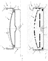
- Fig. 1a shows an aerator 1 with an aerating element 2 for introducing a gas into a liquid.
- the ventilation element 2 has an elongated base body 3, which can be formed by a profile part known per se, in particular made of plastic.
- the base body 3 has on the upper side a curved base plate with a gas supply opening 4 'which is connected to a gas supply device 4 ′′.
- the ventilation element 2 has a (in Fig. 2a schematically visible) membrane element 5 with a plurality of passage openings for the gas in order to aerate the gas in the liquid to be aerated, for example in a clarifier.
- the ventilation element 2 On each of the side edges, the ventilation element 2 has a protruding, in the operating position essentially vertical side wall 6, which extends in the longitudinal direction of the ventilation element 2.
- the base body 3 has a clamping groove 7 on each of the lateral edge regions, adjacent to the side walls 6, for clamping edge regions of the membrane element 5 by means of clamping bodies 5 '.
- the structure of the ventilation element 2 is in itself from the AT 506 717 known to which reference can be made.
- the aerator 1 also has an assembly device 8 for assembling the aeration element 2 in the clarifier.
- the mounting device 8 has a mounting element 9 which, in the embodiment shown, has two holding webs 10 for releasable connection to the side walls 6 of the base body 3 of the ventilation element 2.
- the holding webs 10 are flexible, so that the ventilation element 2 can be detachably mounted in the mounting element 9 via a form fit.
- the two opposing retaining webs 10 are connected to one another via a fastening section 11 which is arranged horizontally in the operating position and which is fastened, for example, to the bottom of the clarifier or to a frame within the clarifier.
- the fastening section 11 has a fastening opening 9 'for the arrangement of a fastening element 9 ", for example a screw.
- the mounting element 9 with the holding webs 10 and the fastening section 11 is formed by a one-piece profile part, preferably made of steel.
- each holding web 10 has a delimiting section 11 'for arrangement on the outer surface of the side wall 6 facing away from the clamping groove 7, each of which consists of an upper 12 and a lower holding section 13 is limited.
- the ventilation element 2 is fixed in the height direction by the holding sections 12, 13.
- the boundary sections 11 'of the holding webs 10 effect a lateral fixation of the ventilation element 2.
- the base body 3 of the ventilation element 2 is arranged between the holding webs 10 of the mounting element 9 so as to be displaceable in its longitudinal direction.
- the lower holding section 13 is connected to the fastening section 11 via a connecting section 14 which extends essentially parallel to the delimiting section 11 'and is essentially vertically arranged during operation. This creates sufficient space on the underside of the ventilation element 2.
- the holding web 10 is connected at the free, upper end to a grip element 15 for the elastic deflection of the holding web 10.
- the grip element 15 and the holding web 10 are formed in one piece.
- the grip element 15 is arranged at an angle to the delimiting section 11 ′ of the holding web 10 in order to facilitate the handling of the assembly device 8.
- the mounting element 9 can have a grip element 15 on both holding webs 10 (cf. Fig. 1a , 2a , 2 B , 3a , 3c ).
- the mounting element 9 can have such a grip element 15 only on one of the two holding webs 10 (cf. Figure 1b , 3b ).
- FIG. 2b see. also Fig. 1a , 1b , an embodiment of the ventilation element 2 is shown, which in the form of the base body 2 of the aerator AT 506 717 corresponds.
- the lower holding section 12 of the holding web 10 is designed as an area of the fastening section 11.
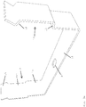
- FIGs 4a to 4d the individual steps in the assembly of the ventilation element 2 in the assembly element 9 can be seen schematically.
- the mounting element 9 is mounted in the clarifier. Thereafter, the ventilation element 2 is inserted into the mounting element 9, with the one (right in the figure) side of the base body 3 below the upper holding section 12 of the one mounting element 9 is arranged. Thereafter, the ventilation element 2 is pressed down, the holding web 10 of the other mounting element 9 is elastically deflected outward.
- the transition area between the holding web 10 and the fastening section 11 is designed as a hinge which enables the holding web 10 to be pivoted out of the rest position outlined with dashed lines into the pivoting position shown in solid lines.
- the ventilation element 2 can slide under the upper holding section 12 of the holding web 10. Due to the inherent elasticity of the material of the mounting element 9, the retaining web 10 then returns to its rest or starting position, whereby the positive connection between the ventilation element 2 and the mounting element 9 is established ( Figure 4d ). By actuating the grip element 15, the holding web can be pressed outwards in order to remove the ventilation element 2 from the assembly device 8.
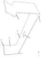
- FIG. 5 an alternative embodiment of the mounting device 8 for mounting the aeration element 2 in the clarifier can be seen.
- Fig. 6 is the aerator 1 together with the assembly device 8 of the Fig. 5 shown.
- the mounting element 9 has two retaining webs 10 for the detachable connection to the side walls 6 of the base body 3 of the ventilation element 2.
- one of the holding webs 10 is connected to a grip element 15 which, in the installed operating state, protrudes upwards over the ventilation element 2.
- the grip element 15 can thus be actuated for the elastic deflection of the holding web 10.
- both holding webs 10 can each be connected to a handle element 15.
- the grip element 15 and the holding web 10 are formed in one piece, as in the previous embodiments.
- the grip element 15 is formed by an extension or continuation of the limiting section 11 ′ of the holding web 10, in particular vertical in the assembled operating state. As a result, the grip element 15 is arranged in the same plane as the delimiting section 11 ′ of the holding web 10.
- the grip element 15 has a recess 16 which corresponds to the upper Holding portion 12 is formed.
- the recess 16 is delimited on the underside by an edge 17 between the upper holding section 12 and the delimiting section 11 ′ of the holding web 10.
- the upper holding section 12 is essentially trapezoidal.
- the recess 16 is delimited by a bending line 18.
- a cutting line 19 corresponding to the upper holding section 12 is provided, whereupon the bending line 18 is formed in the grip element 15 which extends the holding web 10.
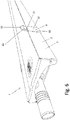
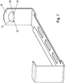
- Fig. 7 shows schematically a further embodiment of the mounting element 9.
- the grip element 15 has an essentially straight line of intersection 20, an adjacent section of the grip element being bent inward to form the upper holding section 12.
- the upper holding section 12 rests in the assembled state via its lower edge 21 on the upper side of the side wall 6 of the ventilation element 2.
- the lower edge 21 of the upper holding section has a substantially trapezoidal profile in the embodiment shown.
- a horizontal free space 22 is provided, which is connected to the recess 16 of the handle element 15, which is shaped corresponding to the upper holding section 12 and extends in a vertical plane.
- This design is characterized by a particularly simple production.
- the mounting element 9 on the fastening section 11 has upwardly curved longitudinal edges with which the rigidity of the mounting element 9 is increased.
Landscapes
- Chemical & Material Sciences (AREA)
- Engineering & Computer Science (AREA)
- Chemical Kinetics & Catalysis (AREA)
- Life Sciences & Earth Sciences (AREA)
- General Engineering & Computer Science (AREA)
- Water Supply & Treatment (AREA)
- Hydrology & Water Resources (AREA)
- Environmental & Geological Engineering (AREA)
- Microbiology (AREA)
- Biodiversity & Conservation Biology (AREA)
- Organic Chemistry (AREA)
- Mechanical Engineering (AREA)
- Aeration Devices For Treatment Of Activated Polluted Sludge (AREA)
- Accessories For Mixers (AREA)
- Separation Using Semi-Permeable Membranes (AREA)
- Apparatus Associated With Microorganisms And Enzymes (AREA)
- Filtering Of Dispersed Particles In Gases (AREA)
- Farming Of Fish And Shellfish (AREA)
Description
- Die Erfindung betrifft einen Belüfter.
- Aus der
AT 506 717 - In den
CH 532 532 A DE 196 45 781 C1 ,DE 88 07 929 U1 undEP 0 806 400 A1 werden andersartige Belüftereinrichtungen beschrieben. - Die
EP 1 107 413 A1 zeigt eine Kabelaufnahmevorrichtung, bei welcher eine Halteeinrichtung verwendet wird. - Aus der
DE 12 66 567 B ist eine Schelle zur Befestigung von Rohren bekannt, mit einer Basis und einem Bügel, welcher zum Festklemmen des Rohres in die Basis eingehakt wird. - Die
US 4,408,742 A beschreibt eine Halteeinrichtung für ein Regenrohr, wobei gegenüberliegende Haltearme vorgesehen sind. - Die
JP H01 132299 - Um die Belüftervorrichtung am Boden des Klärbeckens zu befestigen, ist die Grundplatte beim Stand der Technik an der Unterseite mit einer Montageplatte verbunden. Der Grundkörper weist dafür horizontale, nach innen vorspringende Halteflansche auf, welche im montierten Zustand von entsprechenden Auslegern der Montageplatte hintergriffen werden. Die Montageplatte wird an gegenüberliegenden Seiten mit dem Boden des Klärbeckens verschraubt. Diese Montagevorrichtung funktioniert grundsätzlich zuverlässig, soll jedoch weiter verbessert werden.
- Demnach besteht die Aufgabe der vorliegenden Erfindung darin, einen konstruktiv einfachen, kostengünstig zu fertigenden Belüfter der eingangs angeführten Art zu schaffen, mit welchem die Montage des Belüftungselementes weiter vereinfacht werden kann.
- Diese Aufgabe wird durch einen Belüfter mit einer Montagevorrichtung, wie in Anspruch 1 angegeben, gelöst. Bevorzugte Ausführungsformen sind in den abhängigen Ansprüchen enthalten.
- Erfindungsgemäß weist das Montageelement zumindest einen elastisch auslenkbaren Haltesteg zur lösbaren Verbindung mit der zumindest einen Seitenwand des Grundkörpers des Belüftungselementes auf, wobei der Haltesteg (10) am freien Ende mit einem Griffelement (15) zum Auslenken des Haltesteges (10) verbunden ist. Erfindungsgemäß ist außerdem die hochragende Seitenwand in der Betriebsstellung im Wesentlichen vertikal.
- Bei der Montage des Belüftungselementes kann der Haltesteg elastisch nach außen gedrückt werden, um die Anordnung des Belüftungselementes in dem Montageelement zu ermöglichen. Nach Beendigung der Belastung kehrt der Haltesteg aufgrund seiner Eigenelastizität in die Ausgangs- bzw. Ruhestellung zurück, wobei das Belüftungselement formschlüssig innerhalb des Montageelementes gehalten wird. Demnach sind der Grundkörper des Belüftungselementes und der Haltesteg des Montageelementes über eine Schnappverbindung miteinander verbindbar. Dadurch kann der Aufwand für die Montage des Belüftungselementes besonders gering gehalten werden. Besonders bevorzugt ist dabei, wenn das Belüftungselement werkzeuglos zwischen den Haltestegen des Montageelementes montierbar ist. Vorteilhafterweise ist es zudem einfach möglich, dass das Belüftungselement aus dem im Klärbecken verankerten Montageelement entfernt wird. Zu diesem Zweck kann der Haltesteg des Montageelementes elastisch nach außen gedrückt werden, woraufhin das Belüftungselement aus dem Montageelement gehoben werden kann. Weiters ist es vorteilhaft, dass der elastisch verformbare Haltesteg mit geringerem Fertigungsaufwand als die beim Stand der Technik vorgesehene Montagevorrichtung verbunden ist. Darüber hinaus kann die Stabilität des Belüfters erhöht werden.
- Um das Belüftungselement auf einfache Weise mit der Montagevorrichtung verbinden und bei Bedarf wieder aus der Montagevorrichtung entfernen zu können, ist es günstig, wenn das Montageelement zwei Haltestege zur lösbaren Verbindung mit gegenüberliegenden Seitenwänden des Grundkörpers des Belüftungselementes aufweist, wobei die zwei Haltestege über einen in einem Klärbecken befestigbaren Befestigungsabschnitt miteinander verbunden sind. Demnach kann die Montagevorrichtung über den Befestigungsabschnitt in dem Klärbecken, beispielsweise am Boden des Klärbeckens oder an einem Gestell innerhalb des Klärbeckens, montiert werden. Aufgrund der biegsamen Ausführung zumindest eines der Haltestege des Montageelementes kann das Belüftungselement lösbar an der Montagevorrichtung montiert werden. Zu diesem Zweck kann das Belüftungselement zunächst in einer gekippten Zwischenstellung in dem Montageelement angeordnet werden, woraufhin das Belüftungselement in seine Betriebsstellung gedrückt werden kann. Durch den Kontakt mit dem Grundkörper wird der zugehörige Haltesteg aus der Ausgangsstellung elastisch nach außen verschwenkt, bis das Belüftungselement in die montierte Betriebsstellung gleitet. Der verformte Haltesteg kehrt danach in seine Ausgangsstellung zurück, wodurch das Belüftungselement in dem Montageelement fixiert wird. Bei dieser Ausführung sind daher die Übergangsbereiche zwischen dem Befestigungsabschnitt und den Haltestegen als Gelenke ausgebildet, welche eine Auslenkung der Haltestege ermöglichen. Um das Belüftungselement aus der Montagevorrichtung zu entfernen, wird zumindest einer der Haltestege des Montageelementes so weit elastisch verformt, dass die Verbindung zwischen dem Grundkörper des Belüftungselementes und dem Montageelement gelöst wird. Bei dieser Ausführungsform ist zudem vorteilhaft, dass das Belüftungselement im montierten Betriebszustand besonders stabil zwischen den gegenüberliegenden Haltestegen des Montageelementes gehalten ist.
- Um das Belüftungselement im montierten Betriebszustand einerseits in Querrichtung und andererseits in vertikaler Richtung zu fixieren, ist es von Vorteil, wenn der Haltesteg einen Begrenzungsabschnitt zur Anordnung an einer Außenfläche der Seitenwand und zumindest einen von dem Begrenzungsabschnitt nach innen ragenden Halteabschnitt aufweist. Bevorzugt ist der Begrenzungsabschnitt, bezogen auf den montierten Betriebszustand, im Wesentlichen vertikal angeordnet. Der Halteabschnitt ist bevorzugt in einem Winkel zu dem Begrenzungsabschnitt angeordnet. Vorzugsweise ist der Halteabschnitt, bezogen auf den montierten Betriebszustand, im Wesentlichen horizontal angeordnet. Durch den Begrenzungsabschnitt wird der Grundkörper des Belüftungselementes im montierten Betriebszustand seitlich gehalten. Der Halteabschnitt bewirkt zudem, dass das Belüftungselement im montierten Betriebszustand gegen eine entsprechende vertikale Verschiebung gesichert ist. Andererseits ist es jedoch günstig, wenn der Begrenzungs- und der Halteabschnitt des Haltesteges dazu eingerichtet sind, eine Verschiebung des Belüftungselementes in dessen Längsrichtung zu ermöglichen. Bevorzugt liegt der Haltesteg des Montageelementes zumindest abschnittsweise an dem Grundkörper des Belüftungselementes an, sodass zum Verschieben des Belüftungselementes der Reibschluss zwischen dem Montageelement und dem Belüftungselement überwunden wird. Vorteilhafterweise kann so die Längsposition des Belüftungselementes innerhalb des Klär- bzw. Abwasserbeckens einfach angepasst werden.
- Um eine Beweglichkeit des Belüftungselementes im montierten Betriebszustand sowohl nach oben als auch nach unten zu sperren, ist es vorteilhaft, wenn der Haltesteg einen oberen und einen unteren Halteabschnitt aufweist. Der obere und der untere Halteabschnitt wirken mit entsprechenden Kanten des Belüfter-Grundkörpers zusammen, um das Belüftungselement in Querrichtung, d.h. seitlich, sowie in vertikaler Richtung zu fixieren.
- Gemäß einer bevorzugten Ausführung ist vorgesehen, dass der untere Halteabschnitt über einen, vorzugsweise im Wesentlichen parallel zum Begrenzungsabschnitt erstreckten, Verbindungsabschnitt mit dem Befestigungsabschnitt verbunden ist. Bei dieser Ausführung ist daher der untere Halteabschnitt oberhalb des Befestigungsabschnittes angeordnet, welcher die gegenüberliegenden Haltestege des Montageelementes miteinander verbindet. Durch den oberen und unteren Halteabschnitt wird in dem Haltesteg eine Ausbuchtung gebildet, in welcher die Seitenwand des Grundkörpers des Belüftungselementes anordenbar ist.
- Gemäß einer alternativen Ausführung ist vorgesehen, dass der untere Halteabschnitt als Bereich des Befestigungsabschnitts ausgebildet ist. Bei dieser Ausführung wird daher die Seitenwand des Belüftungselementes im montierten Betriebszustand zwischen dem oberen Halteabschnitt und dem seitlichen Bereich des Befestigungsabschnittes des Montageelementes gehalten.
- Aus fertigungstechnischen Gründen ist es besonders günstig, wenn das Montageelement durch ein einteiliges Profilteil gebildet ist. Diese Ausführung zeichnet sich durch geringe Fertigungskosten aus. Das Profilteil weist eine in Längsrichtung des Belüftungselementes gleichbleibende Querschnittsform auf. Bevorzugt ist das Profilteil aus Stahl gefertigt. Alternativ kann eine Ausführung aus Kunststoff oder faserverstärktem Kunststoff vorgesehen sein.
- Um die Demontage des Belüftungselementes zu erleichtern, ist erfindungsgemäß der Haltesteg am freien Ende mit einem Griffelement zum Auslenken des Haltestegs verbunden. Zur Demontage des Belüftungselementes kann daher das Griffelement ergriffen werden, um den damit verbundenen Haltesteg nach außen zu biegen, sodass das Belüftungselement aus der Montagevorrichtung entnommen werden kann.
- Darüber hinaus ist es aus Gründen der Stabilität günstig, wenn das Griffelement und der Haltesteg einteilig ausgebildet sind. Dadurch können zudem die Fertigungskosten niedrig gehalten werden.
- Gemäß einer besonders einfach zu fertigenden Ausführungsform kann das Griffelement in derselben Ebene wie der Begrenzungsabschnitt des Haltesteges angeordnet sein. Bei dieser Ausführungsform bildet das Griffelement eine Fortsetzung bzw. Verlängerung des Begrenzungsabschnittes des Haltesteges.
- Hinsichtlich des Fertigungsaufwandes besonders günstig ist es, wenn das Griffelement eine Ausnehmung aufweist, welche vorzugsweise entsprechend dem oberen Halteabschnitt geformt ist. Auf diese Weise kann der Halteabschnitt in der Fertigung aus dem Griffelement gebildet werden. Zu diesem Zweck können Schnitt- und Biegelinien in dem Montageelementvorgesehen sein, um den oberen Halteabschnitt auszubilden. In der Fertigung kann zunächst eine Schnittlinie in einem Ausgangsmaterial für das Griffelement erzeugt werden, woraufhin ein daran angrenzender Abschnitt des Griffelements zur Ausbildung des oberen Halteabschnittes gebogen werden kann.
- In einer bevorzugten Ausführung ist die Ausnehmung des Griffelements abschnittsweise durch eine Kante zwischen dem oberen Halteabschnitt und dem Begrenzungsabschnitt des Haltesteges begrenzt. Bei dieser Ausführung liegt der obere Halteabschnitt im montierten Zustand flächig an der Oberseite der Seitenwand des Belüftungselements an. Bevorzugt ist der obere Halteabschnitt im Wesentlichen halbkreisförmig oder trapezförmig. Die Schnittlinie kann bei dieser Ausführung der Begrenzungslinie des im Wesentlichen halbkreisförmigen oder trapezförmigen oberen Halteabschnitts entsprechen.
- In einer weiteren, besonders einfach zu fertigenden Ausführung weist das Griffelement eine im Wesentlichen geradlinige Schnittlinie auf, wobei ein daran angrenzender Abschnitt des Griffelements zur Ausbildung des oberen Halteabschnitts nach innen gebogen ist. Bei dieser Ausführung liegt der obere Halteabschnitt im montierten Zustand über dessen Unterkante an der Oberseite der Seitenwand des Belüftungselements an. Die Unterkante des oberen Halteabschnitts weist vorzugsweise einen im Wesentlichen halbkreisförmigen oder trapezförmigen Verlauf auf. Zwischen der Unterkante des Halteabschnitts und der im Wesentlichen geradlinigen Schnittlinie am Griffelement kann ein vorzugsweise in einer horizontalen Ebene erstreckter Freiraum ausgebildet sein, welcher mit der entsprechend dem Halteabschnitt geformten, vorzugsweise in einer vertikalen Ebene erstreckten Ausnehmung des Griffelements verbunden ist.
- Dementsprechend kann der Haltesteg eine weitere Ausnehmung aufweisen, welche entsprechend dem unteren Halteabschnitt des Haltesteges geformt ist.
- Um die Handhabung der Montagevorrichtung bei der Montage des Belüftungselementes zu erleichtern, ist es vorteilhaft, wenn das Griffelement von dem Begrenzungsabschnitt des Haltesteges vorzugsweise nach außen abgewinkelt ist.
- Die Ausgestaltung des Montageelementes ermöglicht zudem, dass der Befestigungsabschnitt eine, vorzugsweise genau eine, Befestigungsöffnung zur Anordnung eines Befestigungselementes aufweisen kann. Vorteilhafterweise kann die Zahl der Befestigungsmittel gegenüber dem Stand der Technik reduziert werden.
- Um die Anordnung des Belüftungselementes innerhalb des Klärbeckens mit geringem Aufwand anpassen zu können, ist es günstig, wenn der Grundkörper des Belüftungselementes in Längsrichtung verschieblich zwischen den Haltestegen des Montageelementes angeordnet ist. Zum Verschieben des Belüftungselementes ist es daher vorzugsweise lediglich erforderlich, den Reibschluss zwischen dem Montageelement und dem Belüftungselement zu überwinden.
- Gemäß einer bevorzugten Ausführung weist der Grundkörper in einem seitlichen Randbereich eine Klemmnut zum Festklemmen eines Membranelementes mit Durchtrittsöffnungen für das Gas auf, wobei die Klemmnut außenseitig durch die Seitenwand begrenzt ist.
- Die Erfindung wird nachstehend anhand von in der Zeichnung dargestellten, bevorzugten Ausführungsbeispielen, auf die sie jedoch nicht beschränkt sein soll, noch weiter erläutert. Im Einzelnen zeigen in der Zeichnung:
-
Fig. 1a eine schaubildliche Ansicht eines erfindungsgemäßen Belüfters, wobei ein Belüftungselement zum Einbringen eines Gases in eine Flüssigkeit in einem im Wesentlichen U-förmigen Montageelement mit elastisch verformbaren Haltestegen montiert ist; -
Fig. 1b eine schaubildliche Ansicht des Belüfters gemäßFig. 1a , jedoch mit einer abgewandelten Ausführung des Montageelementes; -
Fig. 2a eine Querschnittsansicht eines erfindungsgemäßen Belüfters mit einem vonFig. 1 verschiedenen Belüftungselement, wobei schematisch eine perforierte Membran in einem an einer Grundplatte aufliegenden Ruhezustand und in einem von der Grundplatte abgehobenen Belüftungszustand dargestellt ist; -
Fig. 2b eine Querschnittsansicht des Belüfters gemäßFig. 1a ; -
Fig. 3a eine Ansicht der Montagevorrichtung für das Belüftungselement gemäßFig. 2a ; -
Fig. 3b eine Ansicht der Montagevorrichtung für das Belüftungselement gemäßFig. 1b ; -
Fig. 3c eine Ansicht einer alternativen Ausführung der Montagevorrichtung für das Belüftungselement gemäßFig. 2b ; -
Fig. 4a bis Fig. 4d schematisch die einzelnen Schritte bei der Montage des Belüftungselementes in dem Montageelement; -
Fig. 5 eine Ansicht einer alternativen Ausführung einer Montagevorrichtung; -
Fig. 6 eine Ansicht eines Belüfters mit der Montagevorrichtung gemäßFig. 5 ; und -
Fig. 7 schematisch eine alternative Ausführung einer Montagevorrichtung. - In
Fig. 1a ist ein Belüfter 1 mit einem Belüftungselement 2 zum Einbringen eines Gases in eine Flüssigkeit gezeigt. Das Belüftungselement 2 weist einen langgestreckten Grundkörper 3 auf, welcher durch ein an sich bekanntes Profilteil, insbesondere aus Kunststoff, gebildet sein kann. Der Grundkörper 3 weist an der Oberseite eine gewölbte Grundplatte mit einer Gaszufuhröffnung 4' auf, welche mit einer Gaszuführeinrichtung 4" verbunden ist. Darüber hinaus weist das Belüftungselement 2 ein (inFig. 2a schematisch ersichtliches) Membranelement 5 mit einer Vielzahl von Durchtrittsöffnungen für das Gas auf, um das Gas in der zu belüftenden Flüssigkeit, beispielsweise in einem Klärbecken, zu belüften. Durch Zufuhr des Gases wird das perforierte Membranelement ausgehend von dem inFig. 2a mit strichlierter Linie eingezeichneten Ruhezustand auf der Grundplatte 3 in den mit einer durchgezogenen Linie angedeuteten Belüftungszustand von der Grundplatte 3 abgehoben. An den Seitenrändern weist das Belüftungselement 2 je eine hochragende, in der Betriebsstellung im Wesentlichen vertikale Seitenwand 6 auf, welche sich in Längsrichtung des Belüftungselementes 2 erstreckt. Der Grundkörper 3 weist an den seitlichen Randbereichen, benachbart der Seitenwände 6, je eine Klemmnut 7 zum Festklemmen von Randbereichen des Membranelementes 5 mittels Klemmkörpern 5' auf. Der Aufbau des Belüftungselementes 2 ist an sich aus derAT 506 717 - Wie aus
Fig. 1a weiters ersichtlich, weist der Belüfter 1 zudem eine Montagevorrichtung 8 zur Montage des Belüftungselementes 2 in dem Klärbecken auf. Die Montagevorrichtung 8 weist ein Montageelement 9 auf, welches in der gezeigten Ausführung zwei Haltestege 10 zur lösbaren Verbindung mit den Seitenwänden 6 des Grundkörpers 3 des Belüftungselementes 2 aufweist. Die Haltestege 10 sind biegsam, sodass das Belüftungselement 2 lösbar, über einen Formschluss in dem Montageelement 9, montierbar ist. - Wie aus
Fig. 2a, 2b ersichtlich, sind die zwei gegenüberliegenden Haltestege 10 über einen in der Betriebsstellung horizontal angeordneten Befestigungsabschnitt 11 miteinander verbunden, welcher beispielsweise am Boden des Klärbeckens oder an einem Gestell innerhalb des Klärbeckens befestigt wird. Dafür weist der Befestigungsabschnitt 11 eine Befestigungsöffnung 9' zur Anordnung eines Befestigungselementes 9", beispielsweise einer Schraube, auf. Das Montageelement 9 mit den Haltestegen 10 und dem Befestigungsabschnitt 11 ist durch ein einteiliges Profilteil, vorzugsweise aus Stahl, gebildet. - Wie aus
Fig. 1a ,1b ,2a, 2b weiters ersichtlich, weist jeder Haltesteg 10 einen Begrenzungsabschnitt 11' zur Anordnung an der von der Klemmnut 7 abgewandten Außenfläche der Seitenwand 6 auf, welcher jeweils von einem oberen 12 und einem unteren Halteabschnitt 13 begrenzt wird. Durch die Halteabschnitte 12, 13 wird das Belüftungselement 2 in Höhenrichtung fixiert. Die Begrenzungsabschnitte 11' der Haltestege 10 bewirken eine seitliche Fixierung des Belüftungselementes 2. Andererseits ist der Grundkörper 3 des Belüftungselementes 2 in dessen Längsrichtung verschieblich zwischen den Haltestegen 10 des Montageelementes 9 angeordnet. - In der Ausführung des Montageelementes 9 gemäß
Fig. 2a undFig. 3a ist der untere Halteabschnitt 13 über einen, im Wesentlichen parallel zum Begrenzungsabschnitt 11' erstreckten, im Betrieb im Wesentlichen vertikal angeordneten Verbindungsabschnitt 14 mit dem Befestigungsabschnitt 11 verbunden. Dadurch wird an der Unterseite des Belüftungselementes 2 ausreichend Platz geschaffen. - Wie aus
Fig. 1a ,1b ,2a, 2b weiters ersichtlich, ist der Haltesteg 10 am freien, oberen Ende mit einem Griffelement 15 zum elastischen Auslenken des Haltesteges 10 verbunden. Das Griffelement 15 und der Haltesteg 10 sind einteilig ausgebildet. In der gezeigten Ausführung ist das Griffelement 15 in einem Winkel zu dem Begrenzungsabschnitt 11' des Haltesteges 10 angeordnet, um die Handhabung der Montagevorrichtung 8 zu erleichtern. Das Montageelement 9 kann an beiden Haltestegen 10 ein Griffelement 15 aufweisen (vgl.Fig. 1a ,2a ,2b ,3a ,3c ). Alternativ kann das Montageelement 9 nur an einem der beiden Haltestege 10 ein solches Griffelement 15 aufweisen (vgl.Fig. 1b ,3b ). - In
Fig. 2b , vgl. auchFig. 1a ,1b , ist eine Ausführungsform des Belüftungselementes 2 gezeigt, welche in der Form des Grundkörpers 2 dem Belüfter derAT 506 717 - In den
Fig. 4a bis Fig. 4d sind schematisch die einzelnen Schritte bei der Montage des Belüftungselementes 2 in dem Montageelement 9 ersichtlich. GemäßFig. 4a wird das Montageelement 9 in dem Klärbecken montiert. Danach wird das Belüftungselement 2 in das Montageelement 9 eingesetzt, wobei die eine (im Bild rechte) Seite des Grundkörpers 3 unterhalb des oberen Halteabschnittes 12 des einen Montageelementes 9 angeordnet wird. Danach wird das Belüftungselement 2 nach unten gedrückt, wobei der Haltesteg 10 des anderen Montageelementes 9 elastisch nach außen gelenkt wird. Der Übergangsbereich zwischen dem Haltesteg 10 und dem Befestigungsabschnitt 11 ist dabei als Gelenk ausgebildet, welches eine Verschwenkung des Haltesteges 10 aus der mit strichlierten Linien skizzierten Ruhestellung nach außen in die mit durchgezogenen Linien dargestellte Schwenkstellung ermöglicht. Dadurch kann das Belüftungselement 2 unter den oberen Halteabschnitt 12 des Haltesteges 10 gleiten. Durch die Eigenelastizität des Materials des Montageelementes 9 kehrt der Haltesteg 10 danach in seine Ruhe- bzw. Ausgangsstellung zurück, wodurch die formschlüssige Verbindung zwischen dem Belüftungselement 2 und dem Montageelement 9 hergestellt wird (Fig. 4d ). Durch Betätigung des Griffelementes 15 kann der Haltesteg nach außen gedrückt werden, um das Belüftungselement 2 aus der Montagevorrichtung 8 zu entnehmen. - In
Fig. 5 ist eine alternative Ausführung der Montagevorrichtung 8 zur Montage des Belüftungselementes 2 in dem Klärbecken ersichtlich. InFig. 6 ist der Belüfter 1 samt der Montagevorrichtung 8 derFig. 5 dargestellt. Das Montageelement 9 weist zwei Haltestege 10 zur lösbaren Verbindung mit den Seitenwänden 6 des Grundkörpers 3 des Belüftungselementes 2 auf. In der gezeigten Ausführung ist einer der Haltestege 10 mit einem Griffelement 15 verbunden, welches im montierten Betriebszustand über das Belüftungselement 2 nach oben vorsteht. Somit kann das Griffelement 15 zum elastischen Auslenken des Haltesteges 10 betätigt werden. Selbstverständlich können jedoch auch beide Haltestege 10 mit je einem Griffelement 15 verbunden sein. Das Griffelement 15 und der Haltesteg 10 sind wie bei den vorangehenden Ausführungen einteilig ausgebildet. Im Unterschied dazu ist das Griffelement 15 jedoch durch eine Verlängerung bzw. Fortsetzung des im montierten Betriebszustand insbesondere vertikalen Begrenzungsabschnittes 11' des Haltesteges 10 gebildet. Dadurch ist das Griffelement 15 in derselben Ebene wie der Begrenzungsabschnitt 11' des Haltesteges 10 angeordnet. Zur Ausbildung des im montierten Betriebszustand im Wesentlichen horizontal angeordneten oberen Halteabschnittes 12 des Haltesteges 10 weist das Griffelement 15 eine Ausnehmung 16 auf, welche entsprechend dem oberen Halteabschnitt 12 geformt ist. Die Ausnehmung 16 wird unterseitig durch eine Kante 17 zwischen dem oberen Halteabschnitt 12 und dem Begrenzungsabschnitt 11' des Haltesteges 10 begrenzt. In der gezeigten Ausführung ist der obere Halteabschnitt 12 im Wesentlichen trapezförmig. Oberseitig ist die Ausnehmung 16 durch eine Biegelinie 18 begrenzt. In der Fertigung wird eine dem oberen Halteabschnitt 12 entsprechende Schnittlinie 19 vorgesehen, woraufhin die Biegelinie 18 in dem den Haltesteg 10 verlängernden Griffelement 15 ausgebildet. -
Fig. 7 zeigt schematisch eine weitere Ausführung des Montageelements 9. Bei dieser Ausführung weist das Griffelement 15 eine im Wesentlichen geradlinige Schnittlinie 20 auf, wobei ein daran angrenzender Abschnitt des Griffelements zur Ausbildung des oberen Halteabschnitts 12 nach innen gebogen ist. Bei dieser Ausführung liegt der obere Halteabschnitt 12 im montierten Zustand über dessen Unterkante 21 an der Oberseite der Seitenwand 6 des Belüftungselements 2 an. Die Unterkante 21 des oberen Halteabschnitts weist in der gezeigten Ausführung einen im Wesentlichen trapezförmigen Verlauf auf. Zwischen der Unterkante 21 des oberen Halteabschnitts 12 und der im Wesentlichen geradlinigen Schnittlinie 20 am Griffelement 15 ist ein horizontaler Freiraum 22 vorgesehen, welcher mit der entsprechend dem oberen Halteabschnitt 12 geformten, in einer vertikalen Ebene erstreckten Ausnehmung 16 des Griffelements 15 verbunden ist. Diese Ausführung zeichnet sich durch eine besonders einfache Fertigung aus. - Wie aus
Fig. 7 weiters ersichtlich, weist das Montageelement 9 bei dieser Ausführung am Befestigungsabschnitt 11 nach oben gebogene Längsränder auf, mit welchen die Steifigkeit des Montageelements 9 erhöht wird.
Claims (15)
- Belüfter (1) mit einem Belüftungselement (2) zum Einbringen eines Gases in eine Flüssigkeit, wobei das Belüftungselement (2) einen Grundkörper (3) mit zumindest einer hochragenden Seitenwand (6) aufweist, und mit einer Montagevorrichtung (8) zur Montage des Belüftungselementes (2) insbesondere in einem Klärbecken, wobei die Montagevorrichtung (8) ein Montageelement (9) zur Verbindung mit der Seitenwand (6) des Grundkörpers (3) des Belüftungselementes (2) aufweist, wobei das Montageelement (9) zumindest einen elastisch auslenkbaren Haltesteg (10) zur lösbaren Verbindung mit der zumindest einen Seitenwand (6) des Grundkörpers (3) des Belüftungselementes (2) aufweist, wobei der Haltesteg (10) am freien Ende mit einem Griffelement (15) zum Auslenken des Haltesteges (10) verbunden ist und wobei die hochragende Seitenwand (6) sich in Längsrichtung des Belüftungselementes (2) erstreckt und in der Betriebsstellung im Wesentlichen vertikal ist.
- Belüfter (1) nach Anspruch 1, dadurch gekennzeichnet, dass das Montageelement (9) zwei Haltestege (10) zur lösbaren Verbindung mit gegenüberliegenden Seitenwänden (6) des Grundkörpers (3) des Belüftungselementes (2) aufweist, wobei die zwei Haltestege (10) über einen in einem Klärbecken befestigbaren Befestigungsabschnitt (11) miteinander verbunden sind.
- Belüfter (1) nach Anspruch 1 oder 2, dadurch gekennzeichnet, dass der Haltesteg (10) einen Begrenzungsabschnitt (11') zur Anordnung an einer Außenfläche der Seitenwand (6) und zumindest einen von dem Begrenzungsabschnitt (11') nach innen ragenden Halteabschnitt (12, 13) aufweist.
- Belüfter (1) nach Anspruch 3, dadurch gekennzeichnet, dass der Haltesteg (10) einen oberen (12) und einen unteren Halteabschnitt (13) aufweist.
- Belüfter (1) nach Anspruch 4, dadurch gekennzeichnet, dass der untere Halteabschnitt (13) über einen vorzugsweise im Wesentlichen parallel zum Begrenzungsabschnitt (11') erstreckten Verbindungsabschnitt (14) mit dem Befestigungsabschnitt (11) verbunden ist.
- Belüfter (1) nach Anspruch 4, dadurch gekennzeichnet, dass der untere Halteabschnitt (13) als Bereich des Befestigungsabschnittes (11) ausgebildet ist.
- Belüfter (1) nach einem der Ansprüche 1 bis 6, dadurch gekennzeichnet, dass das Montageelement (9) durch ein einteiliges Profilteil gebildet ist.
- Belüfter (1) nach einem der Ansprüche 1 bis 7, dadurch gekennzeichnet, dass das Griffelement (15) und der Haltesteg (10) einteilig ausgebildet sind.
- Belüfter (1) nach einem der Ansprüche 1 bis 8, dadurch gekennzeichnet, dass das Griffelement (15) in derselben Ebene wie der Begrenzungsabschnitt (11') des Haltesteges (10) angeordnet ist.
- Belüfter (1) nach einem der Ansprüche 1 bis 9, dadurch gekennzeichnet, dass das Griffelement (15) eine Ausnehmung (16) aufweist, welche vorzugsweise entsprechend dem oberen Halteabschnitt (12) geformt ist.
- Belüfter (1) nach einem der Ansprüche 1 bis 10, dadurch gekennzeichnet, dass das Griffelement (15) eine im Wesentlichen geradlinige Schnittlinie (20) aufweist, wobei ein daran angrenzender Abschnitt des Griffelements (15) zur Ausbildung des oberen Halteabschnitts (12) nach innen gebogen ist, wobei der obere Halteabschnitt (12) im montierten Zustand über dessen Unterkante (21) an der Oberseite der Seitenwand (6) des Belüftungselements (2) anliegt.
- Belüfter (1) nach einem der Ansprüche 1 bis 8, dadurch gekennzeichnet, dass das Griffelement (15) von dem Begrenzungsabschnitt (11') des Haltesteges (10) vorzugsweise nach außen abgewinkelt ist.
- Belüfter (1) nach einem der Ansprüche 1 bis 12, dadurch gekennzeichnet, dass der Befestigungsabschnitt (11) eine, vorzugsweise genau eine, Befestigungsöffnung (9') zur Anordnung eines Befestigungselementes (9") aufweist.
- Belüfter (1) nach einem der Ansprüche 1 bis 13, dadurch gekennzeichnet, dass der Grundkörper (3) des Belüftungselementes (2) in Längsrichtung verschieblich zwischen den Haltestegen (10) des Montageelementes (9) angeordnet ist.
- Belüfter (1) nach einem der Ansprüche 1 bis 14, dadurch gekennzeichnet, dass der Grundkörper (3) in einem seitlichen Randbereich eine Klemmnut (7) zum Festklemmen eines Membranelementes (5) mit Durchtrittsöffnungen für das Gas aufweist, wobei die Klemmnut (7) außenseitig durch die Seitenwand (6) begrenzt ist.
Applications Claiming Priority (2)
| Application Number | Priority Date | Filing Date | Title |
|---|---|---|---|
| ATGM50067/2014U AT14362U1 (de) | 2014-05-02 | 2014-05-02 | Montagevorrichtung für ein Belüftungselement und Belüfter eines solchen Belüftungselementes |
| PCT/AT2015/050108 WO2015164900A1 (de) | 2014-05-02 | 2015-04-30 | Montagevorrichtung für ein belüftungselement und belüfter |
Publications (2)
| Publication Number | Publication Date |
|---|---|
| EP3137802A1 EP3137802A1 (de) | 2017-03-08 |
| EP3137802B1 true EP3137802B1 (de) | 2020-12-02 |
Family
ID=54054157
Family Applications (1)
| Application Number | Title | Priority Date | Filing Date |
|---|---|---|---|
| EP15744850.7A Active EP3137802B1 (de) | 2014-05-02 | 2015-04-30 | Belüfter mit montagevorrichtung |
Country Status (7)
| Country | Link |
|---|---|
| US (1) | US10625218B2 (de) |
| EP (1) | EP3137802B1 (de) |
| JP (1) | JP6650437B2 (de) |
| CN (1) | CN106457169B (de) |
| AT (1) | AT14362U1 (de) |
| AU (1) | AU2015252739B2 (de) |
| WO (1) | WO2015164900A1 (de) |
Families Citing this family (5)
| Publication number | Priority date | Publication date | Assignee | Title |
|---|---|---|---|---|
| CN111068530B (zh) * | 2018-10-22 | 2022-02-22 | 中国石油天然气股份有限公司 | 微气泡生成装置及设备 |
| US20220322652A1 (en) * | 2021-04-12 | 2022-10-13 | Casey W. Shope | Cable clamp for trapping |
| US12251669B2 (en) * | 2021-04-16 | 2025-03-18 | En Solución | Shear flow nanobubble generator |
| CN113202172B (zh) * | 2021-05-31 | 2022-05-10 | 鹏图建设有限公司 | 一种便于缓解市政道路积水的排水系统 |
| AT527914B1 (de) * | 2024-02-27 | 2025-08-15 | Aquaconsult Anlagenbau Gmbh | Belüfter |
Citations (1)
| Publication number | Priority date | Publication date | Assignee | Title |
|---|---|---|---|---|
| JPH01132299U (de) * | 1988-02-29 | 1989-09-07 |
Family Cites Families (24)
| Publication number | Priority date | Publication date | Assignee | Title |
|---|---|---|---|---|
| US3295806A (en) | 1964-10-03 | 1967-01-03 | Modeme Robert | Two part clip for attaching a cylindrical member to a support |
| CH532532A (de) | 1971-12-29 | 1973-01-15 | Fischer Ag Georg | Belüftungsvorrichtung für Abwässer |
| US4410027A (en) * | 1978-10-18 | 1983-10-18 | Lucous Robert W | Retainer strip assembly for flexible sheet material |
| US4408742A (en) * | 1981-02-17 | 1983-10-11 | Korb George P | Hanger for rectangular-section downspouts |
| JPH01124297U (de) * | 1988-02-19 | 1989-08-24 | ||
| DE8807929U1 (de) | 1988-06-20 | 1988-08-18 | Messner, Rudolf, 8555 Adelsdorf | Verbindungsvorrichtung |
| EP0806400A1 (de) * | 1996-05-07 | 1997-11-12 | Reinhart Dr.-Ing. Von Nordenskjöld | Bogenbelüfter |
| DE19645781C1 (de) * | 1996-11-07 | 1998-05-28 | Ott Rita | Befestigungsvorrichtung für eine Begasungseinrichtung |
| FR2801439B1 (fr) | 1999-11-24 | 2001-12-14 | Mavil | Procede d'assemblage d'un chemin de cables et ensemble de troncons allonges formant un tel chemin de cables |
| DE10041147A1 (de) * | 2000-08-21 | 2002-03-07 | Andreas Jaeger | Vorrichtung zum Befestigen von Wasserbelüftungseinrichtungen an Luftzuführungsleitungen |
| JP4056281B2 (ja) * | 2002-04-10 | 2008-03-05 | 日本碍子株式会社 | 散気板ホルダーを利用したメンブレン散気装置 |
| US8002249B2 (en) * | 2002-08-13 | 2011-08-23 | Itt Manufacturing Enterprises, Inc. | Strip diffuser |
| CN1321728C (zh) * | 2002-08-13 | 2007-06-20 | Itt制造企业公司 | 带状扩散器pct i |
| AT413380B (de) * | 2004-05-28 | 2006-02-15 | Meyer Udo Dipl Ing | Einrichtung zum befestigen einer perforierten belüfter-membran |
| JP4987752B2 (ja) * | 2008-02-22 | 2012-07-25 | 三菱電線工業株式会社 | 散気装置 |
| AT506717A1 (de) | 2008-05-02 | 2009-11-15 | Aquaconsult Anlagenbau Gmbh | Vorrichtung zum eintragen von gasbläschen in eine flüssigkeit |
| KR101020804B1 (ko) * | 2008-07-07 | 2011-03-09 | 주식회사 신일 | 오수 처리용 멤브레인 산기관의 이물질 제거 장치 |
| US8371561B2 (en) * | 2010-04-12 | 2013-02-12 | Xylem Ip Holdings Llc | Aeration diffuser assembly end seal |
| DE102012108400B4 (de) * | 2012-09-10 | 2022-07-21 | Alexander Ott | Standrohranordnung samt Befestigung zur Aufnahme und zur Gasversorgung von Belüftungskörpern in einem Abwasserklärbecken |
| US9370752B2 (en) * | 2013-03-15 | 2016-06-21 | Artemis Rubber Technology, Inc. | Aeration element for the gasification of liquids |
| US10105659B2 (en) * | 2013-03-15 | 2018-10-23 | Claudius Jaeger | Dual control lateral air manifold assembly |
| US9561480B2 (en) * | 2013-03-15 | 2017-02-07 | Claudius Jaeger | Assembly bracket and mounting system for aeration element |
| SE536982C2 (sv) * | 2013-03-18 | 2014-11-25 | Xylem Ip Man S R L | Luftarsammansättning för spridning av en gas i en vätska |
| DE102013106845B4 (de) * | 2013-07-01 | 2017-06-14 | NORRES Beteiligungs-GmbH | Vorrichtung zur Verteilung von Gasen in Flüssigkeiten |
-
2014
- 2014-05-02 AT ATGM50067/2014U patent/AT14362U1/de not_active IP Right Cessation
-
2015
- 2015-04-30 CN CN201580022276.2A patent/CN106457169B/zh active Active
- 2015-04-30 US US15/308,228 patent/US10625218B2/en active Active
- 2015-04-30 JP JP2017508713A patent/JP6650437B2/ja active Active
- 2015-04-30 EP EP15744850.7A patent/EP3137802B1/de active Active
- 2015-04-30 AU AU2015252739A patent/AU2015252739B2/en active Active
- 2015-04-30 WO PCT/AT2015/050108 patent/WO2015164900A1/de not_active Ceased
Patent Citations (1)
| Publication number | Priority date | Publication date | Assignee | Title |
|---|---|---|---|---|
| JPH01132299U (de) * | 1988-02-29 | 1989-09-07 |
Also Published As
| Publication number | Publication date |
|---|---|
| CN106457169A (zh) | 2017-02-22 |
| AU2015252739B2 (en) | 2019-10-17 |
| US20170050155A1 (en) | 2017-02-23 |
| AU2015252739A1 (en) | 2016-11-03 |
| AT14362U1 (de) | 2015-09-15 |
| CN106457169B (zh) | 2019-12-10 |
| US10625218B2 (en) | 2020-04-21 |
| JP6650437B2 (ja) | 2020-02-19 |
| WO2015164900A1 (de) | 2015-11-05 |
| JP2017514688A (ja) | 2017-06-08 |
| AU2015252739A2 (en) | 2017-01-12 |
| EP3137802A1 (de) | 2017-03-08 |
Similar Documents
| Publication | Publication Date | Title |
|---|---|---|
| EP3137802B1 (de) | Belüfter mit montagevorrichtung | |
| DE60307910T2 (de) | Abstandshalter für Wirbelkörper | |
| AT413380B (de) | Einrichtung zum befestigen einer perforierten belüfter-membran | |
| DE202004015811U1 (de) | Befestigungsvorrichtung für mindestens einen Sonnenkollektor | |
| DE102006032826A1 (de) | Stabilisator zur Anlenkung einer Stabilisatorstange an einem Kraftfahrzeug | |
| EP2275694A1 (de) | Befestigungseinrichtung zu einer Schraubbefestigung an einer Montageschiene | |
| EP2249102A2 (de) | Verbinder für eine Profilschiene | |
| EP2476819A1 (de) | Halterung für Dielen oder Bretter | |
| EP0458254A2 (de) | Befestigungsvorrichtung zur Befestigung eines Griffelementes an einem Kochgeschirr | |
| EP2378209B1 (de) | Dunstabzugshaube | |
| EP1688551B1 (de) | Befestigungselement für eine Montageschiene und Schienenanordnung | |
| EP2045407A1 (de) | Entwässeungsrinne und Halterungsvorrichtung | |
| DE4335000C2 (de) | U-förmiges Verbindungselement zur Verbindung von C-Profilschienen aus Metall | |
| EP2847136B1 (de) | Befestigung eines streifenbelüfters | |
| DE102010055547B4 (de) | Kabeltragsystem umfassend eine Konsole und eine Gitterrinne | |
| DE102016124988B4 (de) | Beschlag und Verfahren für das Verlegen von Terrassendielen | |
| EP1932972B1 (de) | Spülkasten mit kombinierter Füllventil- und Ablaufventilsitzhalterung | |
| DE20215863U1 (de) | Vorrichtung zum Verbinden zweier Schienen | |
| AT527914B1 (de) | Belüfter | |
| DE4419920C2 (de) | Traufenlüftungsprofil | |
| DE102004036634A1 (de) | Vorrichtung zum Begasen von Flüssigkeiten und Verfahren zur Montage der Vorrichtung | |
| EP4030103B1 (de) | Kochfeld mit steuerungsgehäuse | |
| AT500069B1 (de) | Kabelhaltebügel | |
| EP0111473A2 (de) | Fachboden aus Blech | |
| DE10046918B4 (de) | Gleitlager für Schiebeböden |
Legal Events
| Date | Code | Title | Description |
|---|---|---|---|
| STAA | Information on the status of an ep patent application or granted ep patent |
Free format text: STATUS: THE INTERNATIONAL PUBLICATION HAS BEEN MADE |
|
| PUAI | Public reference made under article 153(3) epc to a published international application that has entered the european phase |
Free format text: ORIGINAL CODE: 0009012 |
|
| STAA | Information on the status of an ep patent application or granted ep patent |
Free format text: STATUS: REQUEST FOR EXAMINATION WAS MADE |
|
| 17P | Request for examination filed |
Effective date: 20161125 |
|
| AK | Designated contracting states |
Kind code of ref document: A1 Designated state(s): AL AT BE BG CH CY CZ DE DK EE ES FI FR GB GR HR HU IE IS IT LI LT LU LV MC MK MT NL NO PL PT RO RS SE SI SK SM TR |
|
| AX | Request for extension of the european patent |
Extension state: BA ME |
|
| STAA | Information on the status of an ep patent application or granted ep patent |
Free format text: STATUS: EXAMINATION IS IN PROGRESS |
|
| RIN1 | Information on inventor provided before grant (corrected) |
Inventor name: LUGMAIR, ROBERT Inventor name: GLANINGER, GERALD Inventor name: KOEBERL, JOSEF |
|
| 17Q | First examination report despatched |
Effective date: 20191025 |
|
| GRAP | Despatch of communication of intention to grant a patent |
Free format text: ORIGINAL CODE: EPIDOSNIGR1 |
|
| STAA | Information on the status of an ep patent application or granted ep patent |
Free format text: STATUS: GRANT OF PATENT IS INTENDED |
|
| INTG | Intention to grant announced |
Effective date: 20200720 |
|
| GRAS | Grant fee paid |
Free format text: ORIGINAL CODE: EPIDOSNIGR3 |
|
| GRAA | (expected) grant |
Free format text: ORIGINAL CODE: 0009210 |
|
| STAA | Information on the status of an ep patent application or granted ep patent |
Free format text: STATUS: THE PATENT HAS BEEN GRANTED |
|
| AK | Designated contracting states |
Kind code of ref document: B1 Designated state(s): AL AT BE BG CH CY CZ DE DK EE ES FI FR GB GR HR HU IE IS IT LI LT LU LV MC MK MT NL NO PL PT RO RS SE SI SK SM TR |
|
| AX | Request for extension of the european patent |
Extension state: BA ME |
|
| REG | Reference to a national code |
Ref country code: GB Ref legal event code: FG4D Free format text: NOT ENGLISH |
|
| REG | Reference to a national code |
Ref country code: AT Ref legal event code: REF Ref document number: 1341286 Country of ref document: AT Kind code of ref document: T Effective date: 20201215 Ref country code: CH Ref legal event code: EP |
|
| REG | Reference to a national code |
Ref country code: DE Ref legal event code: R096 Ref document number: 502015013950 Country of ref document: DE |
|
| REG | Reference to a national code |
Ref country code: IE Ref legal event code: FG4D Free format text: LANGUAGE OF EP DOCUMENT: GERMAN |
|
| PG25 | Lapsed in a contracting state [announced via postgrant information from national office to epo] |
Ref country code: FI Free format text: LAPSE BECAUSE OF FAILURE TO SUBMIT A TRANSLATION OF THE DESCRIPTION OR TO PAY THE FEE WITHIN THE PRESCRIBED TIME-LIMIT Effective date: 20201202 Ref country code: RS Free format text: LAPSE BECAUSE OF FAILURE TO SUBMIT A TRANSLATION OF THE DESCRIPTION OR TO PAY THE FEE WITHIN THE PRESCRIBED TIME-LIMIT Effective date: 20201202 Ref country code: NO Free format text: LAPSE BECAUSE OF FAILURE TO SUBMIT A TRANSLATION OF THE DESCRIPTION OR TO PAY THE FEE WITHIN THE PRESCRIBED TIME-LIMIT Effective date: 20210302 Ref country code: GR Free format text: LAPSE BECAUSE OF FAILURE TO SUBMIT A TRANSLATION OF THE DESCRIPTION OR TO PAY THE FEE WITHIN THE PRESCRIBED TIME-LIMIT Effective date: 20210303 |
|
| REG | Reference to a national code |
Ref country code: NL Ref legal event code: MP Effective date: 20201202 |
|
| PG25 | Lapsed in a contracting state [announced via postgrant information from national office to epo] |
Ref country code: SE Free format text: LAPSE BECAUSE OF FAILURE TO SUBMIT A TRANSLATION OF THE DESCRIPTION OR TO PAY THE FEE WITHIN THE PRESCRIBED TIME-LIMIT Effective date: 20201202 Ref country code: PL Free format text: LAPSE BECAUSE OF FAILURE TO SUBMIT A TRANSLATION OF THE DESCRIPTION OR TO PAY THE FEE WITHIN THE PRESCRIBED TIME-LIMIT Effective date: 20201202 Ref country code: LV Free format text: LAPSE BECAUSE OF FAILURE TO SUBMIT A TRANSLATION OF THE DESCRIPTION OR TO PAY THE FEE WITHIN THE PRESCRIBED TIME-LIMIT Effective date: 20201202 Ref country code: BG Free format text: LAPSE BECAUSE OF FAILURE TO SUBMIT A TRANSLATION OF THE DESCRIPTION OR TO PAY THE FEE WITHIN THE PRESCRIBED TIME-LIMIT Effective date: 20210302 |
|
| PG25 | Lapsed in a contracting state [announced via postgrant information from national office to epo] |
Ref country code: HR Free format text: LAPSE BECAUSE OF FAILURE TO SUBMIT A TRANSLATION OF THE DESCRIPTION OR TO PAY THE FEE WITHIN THE PRESCRIBED TIME-LIMIT Effective date: 20201202 Ref country code: NL Free format text: LAPSE BECAUSE OF FAILURE TO SUBMIT A TRANSLATION OF THE DESCRIPTION OR TO PAY THE FEE WITHIN THE PRESCRIBED TIME-LIMIT Effective date: 20201202 |
|
| REG | Reference to a national code |
Ref country code: LT Ref legal event code: MG9D |
|
| PG25 | Lapsed in a contracting state [announced via postgrant information from national office to epo] |
Ref country code: EE Free format text: LAPSE BECAUSE OF FAILURE TO SUBMIT A TRANSLATION OF THE DESCRIPTION OR TO PAY THE FEE WITHIN THE PRESCRIBED TIME-LIMIT Effective date: 20201202 Ref country code: CZ Free format text: LAPSE BECAUSE OF FAILURE TO SUBMIT A TRANSLATION OF THE DESCRIPTION OR TO PAY THE FEE WITHIN THE PRESCRIBED TIME-LIMIT Effective date: 20201202 Ref country code: SM Free format text: LAPSE BECAUSE OF FAILURE TO SUBMIT A TRANSLATION OF THE DESCRIPTION OR TO PAY THE FEE WITHIN THE PRESCRIBED TIME-LIMIT Effective date: 20201202 Ref country code: SK Free format text: LAPSE BECAUSE OF FAILURE TO SUBMIT A TRANSLATION OF THE DESCRIPTION OR TO PAY THE FEE WITHIN THE PRESCRIBED TIME-LIMIT Effective date: 20201202 Ref country code: PT Free format text: LAPSE BECAUSE OF FAILURE TO SUBMIT A TRANSLATION OF THE DESCRIPTION OR TO PAY THE FEE WITHIN THE PRESCRIBED TIME-LIMIT Effective date: 20210405 Ref country code: RO Free format text: LAPSE BECAUSE OF FAILURE TO SUBMIT A TRANSLATION OF THE DESCRIPTION OR TO PAY THE FEE WITHIN THE PRESCRIBED TIME-LIMIT Effective date: 20201202 Ref country code: LT Free format text: LAPSE BECAUSE OF FAILURE TO SUBMIT A TRANSLATION OF THE DESCRIPTION OR TO PAY THE FEE WITHIN THE PRESCRIBED TIME-LIMIT Effective date: 20201202 |
|
| REG | Reference to a national code |
Ref country code: DE Ref legal event code: R097 Ref document number: 502015013950 Country of ref document: DE |
|
| PG25 | Lapsed in a contracting state [announced via postgrant information from national office to epo] |
Ref country code: IS Free format text: LAPSE BECAUSE OF FAILURE TO SUBMIT A TRANSLATION OF THE DESCRIPTION OR TO PAY THE FEE WITHIN THE PRESCRIBED TIME-LIMIT Effective date: 20210402 |
|
| PLBE | No opposition filed within time limit |
Free format text: ORIGINAL CODE: 0009261 |
|
| STAA | Information on the status of an ep patent application or granted ep patent |
Free format text: STATUS: NO OPPOSITION FILED WITHIN TIME LIMIT |
|
| PG25 | Lapsed in a contracting state [announced via postgrant information from national office to epo] |
Ref country code: AL Free format text: LAPSE BECAUSE OF FAILURE TO SUBMIT A TRANSLATION OF THE DESCRIPTION OR TO PAY THE FEE WITHIN THE PRESCRIBED TIME-LIMIT Effective date: 20201202 |
|
| 26N | No opposition filed |
Effective date: 20210903 |
|
| PG25 | Lapsed in a contracting state [announced via postgrant information from national office to epo] |
Ref country code: MC Free format text: LAPSE BECAUSE OF FAILURE TO SUBMIT A TRANSLATION OF THE DESCRIPTION OR TO PAY THE FEE WITHIN THE PRESCRIBED TIME-LIMIT Effective date: 20201202 Ref country code: DK Free format text: LAPSE BECAUSE OF FAILURE TO SUBMIT A TRANSLATION OF THE DESCRIPTION OR TO PAY THE FEE WITHIN THE PRESCRIBED TIME-LIMIT Effective date: 20201202 Ref country code: ES Free format text: LAPSE BECAUSE OF FAILURE TO SUBMIT A TRANSLATION OF THE DESCRIPTION OR TO PAY THE FEE WITHIN THE PRESCRIBED TIME-LIMIT Effective date: 20201202 Ref country code: SI Free format text: LAPSE BECAUSE OF FAILURE TO SUBMIT A TRANSLATION OF THE DESCRIPTION OR TO PAY THE FEE WITHIN THE PRESCRIBED TIME-LIMIT Effective date: 20201202 |
|
| PG25 | Lapsed in a contracting state [announced via postgrant information from national office to epo] |
Ref country code: LU Free format text: LAPSE BECAUSE OF NON-PAYMENT OF DUE FEES Effective date: 20210430 |
|
| REG | Reference to a national code |
Ref country code: BE Ref legal event code: MM Effective date: 20210430 |
|
| PG25 | Lapsed in a contracting state [announced via postgrant information from national office to epo] |
Ref country code: LI Free format text: LAPSE BECAUSE OF NON-PAYMENT OF DUE FEES Effective date: 20210430 Ref country code: CH Free format text: LAPSE BECAUSE OF NON-PAYMENT OF DUE FEES Effective date: 20210430 Ref country code: FR Free format text: LAPSE BECAUSE OF NON-PAYMENT OF DUE FEES Effective date: 20210430 |
|
| PG25 | Lapsed in a contracting state [announced via postgrant information from national office to epo] |
Ref country code: IE Free format text: LAPSE BECAUSE OF NON-PAYMENT OF DUE FEES Effective date: 20210430 |
|
| PG25 | Lapsed in a contracting state [announced via postgrant information from national office to epo] |
Ref country code: IS Free format text: LAPSE BECAUSE OF FAILURE TO SUBMIT A TRANSLATION OF THE DESCRIPTION OR TO PAY THE FEE WITHIN THE PRESCRIBED TIME-LIMIT Effective date: 20210402 |
|
| PG25 | Lapsed in a contracting state [announced via postgrant information from national office to epo] |
Ref country code: BE Free format text: LAPSE BECAUSE OF NON-PAYMENT OF DUE FEES Effective date: 20210430 |
|
| PG25 | Lapsed in a contracting state [announced via postgrant information from national office to epo] |
Ref country code: HU Free format text: LAPSE BECAUSE OF FAILURE TO SUBMIT A TRANSLATION OF THE DESCRIPTION OR TO PAY THE FEE WITHIN THE PRESCRIBED TIME-LIMIT; INVALID AB INITIO Effective date: 20150430 |
|
| P01 | Opt-out of the competence of the unified patent court (upc) registered |
Effective date: 20230522 |
|
| PG25 | Lapsed in a contracting state [announced via postgrant information from national office to epo] |
Ref country code: CY Free format text: LAPSE BECAUSE OF FAILURE TO SUBMIT A TRANSLATION OF THE DESCRIPTION OR TO PAY THE FEE WITHIN THE PRESCRIBED TIME-LIMIT Effective date: 20201202 |
|
| PG25 | Lapsed in a contracting state [announced via postgrant information from national office to epo] |
Ref country code: MK Free format text: LAPSE BECAUSE OF FAILURE TO SUBMIT A TRANSLATION OF THE DESCRIPTION OR TO PAY THE FEE WITHIN THE PRESCRIBED TIME-LIMIT Effective date: 20201202 |
|
| VS25 | Lapsed in a validation state [announced via postgrant information from nat. office to epo] |
Ref country code: MA Free format text: LAPSE BECAUSE OF FAILURE TO SUBMIT A TRANSLATION OF THE DESCRIPTION OR TO PAY THE FEE WITHIN THE PRESCRIBED TIME-LIMIT Effective date: 20201202 |
|
| PG25 | Lapsed in a contracting state [announced via postgrant information from national office to epo] |
Ref country code: MT Free format text: LAPSE BECAUSE OF FAILURE TO SUBMIT A TRANSLATION OF THE DESCRIPTION OR TO PAY THE FEE WITHIN THE PRESCRIBED TIME-LIMIT Effective date: 20201202 |
|
| PGFP | Annual fee paid to national office [announced via postgrant information from national office to epo] |
Ref country code: DE Payment date: 20250417 Year of fee payment: 11 |
|
| PGFP | Annual fee paid to national office [announced via postgrant information from national office to epo] |
Ref country code: GB Payment date: 20250423 Year of fee payment: 11 |
|
| PGFP | Annual fee paid to national office [announced via postgrant information from national office to epo] |
Ref country code: IT Payment date: 20250430 Year of fee payment: 11 |
|
| PGFP | Annual fee paid to national office [announced via postgrant information from national office to epo] |
Ref country code: AT Payment date: 20250409 Year of fee payment: 11 |
|
| PG25 | Lapsed in a contracting state [announced via postgrant information from national office to epo] |
Ref country code: TR Free format text: LAPSE BECAUSE OF FAILURE TO SUBMIT A TRANSLATION OF THE DESCRIPTION OR TO PAY THE FEE WITHIN THE PRESCRIBED TIME-LIMIT Effective date: 20201202 |