EP3137784B1 - Dispositif destiné à simuler l'application d'une force sur un élément d'actionnement d'un véhicule, de préférence simulateur de pédale, et dispositif permettant d'actionner un système d'embrayage électrique - Google Patents
Dispositif destiné à simuler l'application d'une force sur un élément d'actionnement d'un véhicule, de préférence simulateur de pédale, et dispositif permettant d'actionner un système d'embrayage électrique Download PDFInfo
- Publication number
- EP3137784B1 EP3137784B1 EP15732154.8A EP15732154A EP3137784B1 EP 3137784 B1 EP3137784 B1 EP 3137784B1 EP 15732154 A EP15732154 A EP 15732154A EP 3137784 B1 EP3137784 B1 EP 3137784B1
- Authority
- EP
- European Patent Office
- Prior art keywords
- piston
- cylinder
- hollow space
- actuating
- liquid
- Prior art date
- Legal status (The legal status is an assumption and is not a legal conclusion. Google has not performed a legal analysis and makes no representation as to the accuracy of the status listed.)
- Not-in-force
Links
- 238000004088 simulation Methods 0.000 title claims description 12
- 239000007788 liquid Substances 0.000 claims description 20
- 230000001419 dependent effect Effects 0.000 claims description 6
- 238000006073 displacement reaction Methods 0.000 claims description 5
- 239000011796 hollow space material Substances 0.000 claims 11
- 239000012530 fluid Substances 0.000 description 21
- 230000008878 coupling Effects 0.000 description 6
- 238000010168 coupling process Methods 0.000 description 6
- 238000005859 coupling reaction Methods 0.000 description 6
- 239000012528 membrane Substances 0.000 description 6
- 230000008901 benefit Effects 0.000 description 2
- 230000008859 change Effects 0.000 description 2
- 230000006835 compression Effects 0.000 description 2
- 238000007906 compression Methods 0.000 description 2
- 230000003247 decreasing effect Effects 0.000 description 2
- 238000010586 diagram Methods 0.000 description 2
- 230000006870 function Effects 0.000 description 2
- 230000004044 response Effects 0.000 description 2
- 238000006243 chemical reaction Methods 0.000 description 1
- 150000001875 compounds Chemical class 0.000 description 1
- 230000000694 effects Effects 0.000 description 1
- 238000011156 evaluation Methods 0.000 description 1
- 230000009467 reduction Effects 0.000 description 1
- 230000001172 regenerating effect Effects 0.000 description 1
- 230000035807 sensation Effects 0.000 description 1
- 230000008054 signal transmission Effects 0.000 description 1
Images

Classifications
-
- B—PERFORMING OPERATIONS; TRANSPORTING
- B60—VEHICLES IN GENERAL
- B60T—VEHICLE BRAKE CONTROL SYSTEMS OR PARTS THEREOF; BRAKE CONTROL SYSTEMS OR PARTS THEREOF, IN GENERAL; ARRANGEMENT OF BRAKING ELEMENTS ON VEHICLES IN GENERAL; PORTABLE DEVICES FOR PREVENTING UNWANTED MOVEMENT OF VEHICLES; VEHICLE MODIFICATIONS TO FACILITATE COOLING OF BRAKES
- B60T7/00—Brake-action initiating means
- B60T7/02—Brake-action initiating means for personal initiation
- B60T7/04—Brake-action initiating means for personal initiation foot actuated
- B60T7/042—Brake-action initiating means for personal initiation foot actuated by electrical means, e.g. using travel or force sensors
-
- B—PERFORMING OPERATIONS; TRANSPORTING
- B60—VEHICLES IN GENERAL
- B60T—VEHICLE BRAKE CONTROL SYSTEMS OR PARTS THEREOF; BRAKE CONTROL SYSTEMS OR PARTS THEREOF, IN GENERAL; ARRANGEMENT OF BRAKING ELEMENTS ON VEHICLES IN GENERAL; PORTABLE DEVICES FOR PREVENTING UNWANTED MOVEMENT OF VEHICLES; VEHICLE MODIFICATIONS TO FACILITATE COOLING OF BRAKES
- B60T11/00—Transmitting braking action from initiating means to ultimate brake actuator without power assistance or drive or where such assistance or drive is irrelevant
- B60T11/10—Transmitting braking action from initiating means to ultimate brake actuator without power assistance or drive or where such assistance or drive is irrelevant transmitting by fluid means, e.g. hydraulic
- B60T11/16—Master control, e.g. master cylinders
- B60T11/18—Connection thereof to initiating means
-
- B—PERFORMING OPERATIONS; TRANSPORTING
- B60—VEHICLES IN GENERAL
- B60T—VEHICLE BRAKE CONTROL SYSTEMS OR PARTS THEREOF; BRAKE CONTROL SYSTEMS OR PARTS THEREOF, IN GENERAL; ARRANGEMENT OF BRAKING ELEMENTS ON VEHICLES IN GENERAL; PORTABLE DEVICES FOR PREVENTING UNWANTED MOVEMENT OF VEHICLES; VEHICLE MODIFICATIONS TO FACILITATE COOLING OF BRAKES
- B60T8/00—Arrangements for adjusting wheel-braking force to meet varying vehicular or ground-surface conditions, e.g. limiting or varying distribution of braking force
- B60T8/32—Arrangements for adjusting wheel-braking force to meet varying vehicular or ground-surface conditions, e.g. limiting or varying distribution of braking force responsive to a speed condition, e.g. acceleration or deceleration
- B60T8/321—Arrangements for adjusting wheel-braking force to meet varying vehicular or ground-surface conditions, e.g. limiting or varying distribution of braking force responsive to a speed condition, e.g. acceleration or deceleration deceleration
- B60T8/3255—Systems in which the braking action is dependent on brake pedal data
- B60T8/326—Hydraulic systems
-
- B—PERFORMING OPERATIONS; TRANSPORTING
- B60—VEHICLES IN GENERAL
- B60T—VEHICLE BRAKE CONTROL SYSTEMS OR PARTS THEREOF; BRAKE CONTROL SYSTEMS OR PARTS THEREOF, IN GENERAL; ARRANGEMENT OF BRAKING ELEMENTS ON VEHICLES IN GENERAL; PORTABLE DEVICES FOR PREVENTING UNWANTED MOVEMENT OF VEHICLES; VEHICLE MODIFICATIONS TO FACILITATE COOLING OF BRAKES
- B60T8/00—Arrangements for adjusting wheel-braking force to meet varying vehicular or ground-surface conditions, e.g. limiting or varying distribution of braking force
- B60T8/32—Arrangements for adjusting wheel-braking force to meet varying vehicular or ground-surface conditions, e.g. limiting or varying distribution of braking force responsive to a speed condition, e.g. acceleration or deceleration
- B60T8/34—Arrangements for adjusting wheel-braking force to meet varying vehicular or ground-surface conditions, e.g. limiting or varying distribution of braking force responsive to a speed condition, e.g. acceleration or deceleration having a fluid pressure regulator responsive to a speed condition
- B60T8/40—Arrangements for adjusting wheel-braking force to meet varying vehicular or ground-surface conditions, e.g. limiting or varying distribution of braking force responsive to a speed condition, e.g. acceleration or deceleration having a fluid pressure regulator responsive to a speed condition comprising an additional fluid circuit including fluid pressurising means for modifying the pressure of the braking fluid, e.g. including wheel driven pumps for detecting a speed condition, or pumps which are controlled by means independent of the braking system
- B60T8/4072—Systems in which a driver input signal is used as a control signal for the additional fluid circuit which is normally used for braking
- B60T8/4081—Systems with stroke simulating devices for driver input
- B60T8/4086—Systems with stroke simulating devices for driver input the stroke simulating device being connected to, or integrated in the driver input device
-
- B—PERFORMING OPERATIONS; TRANSPORTING
- B60—VEHICLES IN GENERAL
- B60T—VEHICLE BRAKE CONTROL SYSTEMS OR PARTS THEREOF; BRAKE CONTROL SYSTEMS OR PARTS THEREOF, IN GENERAL; ARRANGEMENT OF BRAKING ELEMENTS ON VEHICLES IN GENERAL; PORTABLE DEVICES FOR PREVENTING UNWANTED MOVEMENT OF VEHICLES; VEHICLE MODIFICATIONS TO FACILITATE COOLING OF BRAKES
- B60T8/00—Arrangements for adjusting wheel-braking force to meet varying vehicular or ground-surface conditions, e.g. limiting or varying distribution of braking force
- B60T8/32—Arrangements for adjusting wheel-braking force to meet varying vehicular or ground-surface conditions, e.g. limiting or varying distribution of braking force responsive to a speed condition, e.g. acceleration or deceleration
- B60T8/34—Arrangements for adjusting wheel-braking force to meet varying vehicular or ground-surface conditions, e.g. limiting or varying distribution of braking force responsive to a speed condition, e.g. acceleration or deceleration having a fluid pressure regulator responsive to a speed condition
- B60T8/40—Arrangements for adjusting wheel-braking force to meet varying vehicular or ground-surface conditions, e.g. limiting or varying distribution of braking force responsive to a speed condition, e.g. acceleration or deceleration having a fluid pressure regulator responsive to a speed condition comprising an additional fluid circuit including fluid pressurising means for modifying the pressure of the braking fluid, e.g. including wheel driven pumps for detecting a speed condition, or pumps which are controlled by means independent of the braking system
- B60T8/4072—Systems in which a driver input signal is used as a control signal for the additional fluid circuit which is normally used for braking
- B60T8/4081—Systems with stroke simulating devices for driver input
- B60T8/409—Systems with stroke simulating devices for driver input characterised by details of the stroke simulating device
-
- G—PHYSICS
- G05—CONTROLLING; REGULATING
- G05G—CONTROL DEVICES OR SYSTEMS INSOFAR AS CHARACTERISED BY MECHANICAL FEATURES ONLY
- G05G5/00—Means for preventing, limiting or returning the movements of parts of a control mechanism, e.g. locking controlling member
- G05G5/03—Means for enhancing the operator's awareness of arrival of the controlling member at a command or datum position; Providing feel, e.g. means for creating a counterforce
-
- G—PHYSICS
- G05—CONTROLLING; REGULATING
- G05G—CONTROL DEVICES OR SYSTEMS INSOFAR AS CHARACTERISED BY MECHANICAL FEATURES ONLY
- G05G1/00—Controlling members, e.g. knobs or handles; Assemblies or arrangements thereof; Indicating position of controlling members
- G05G1/30—Controlling members actuated by foot
Definitions
- the invention relates to a device for force simulation on an actuating element of a vehicle, preferably a pedal simulator, which conveys a haptic feedback via a predetermined force-displacement behavior, comprising a piston-cylinder unit, wherein a piston is connected via a piston rod with the actuating element which axially moves the piston within the cylinder and means for actuating an electrical coupling system.
- a pedal force simulator for a vehicle brake system with electronic signal transmission in which a, dependent on the foot force of the driver driving the braking torque, in particular by means of electro-hydraulic or electro-mechanical systems is performed, the pedal force simulator generates a familiar for a vehicle driver brake feel.
- the pedal force simulator comprises a pneumatically operating piston-cylinder unit whose piston delimits a compression chamber with a controllable valve and counteracts the compression direction by means of at least one first spring element, the piston with a force and is connected via a piston rod with a vehicle brake pedal such that the piston rod during the operation of the vehicle brake pedal undergoes a change in angle relative to the piston-cylinder unit.
- This angular mobility makes high demands on the design of the pedal force simulator.
- the EP 1 142 766 A1 discloses an accelerator pedal simulator having a variable flow resistance in response to the actuation force and the actuation path.
- the DE 10 2010 061 439 A1 discloses a braking system for a motor vehicle in which a brake pedal operable by a vehicle operator is connected to a pedal simulator for producing a path-dependent counteracting force.
- the position of the brake pedal is detected by means of a sensor and its sensor signal is supplied to the control unit for evaluation.
- the controller According to the position of the brake pedal, the controller generates control signals for a drive control unit and a brake control unit, so that a generated regenerative brake component together with the friction brake component generates a braking torque or a braking effect, which corresponds to the position of the brake pedal.
- the pedal simulator is actuated by the control unit in such a way that an opposing force or restoring force acts on the brake pedal, ie a path-force dependency is established which gives the driver a pedal feel, as in braking only with a hydraulic brake system.
- the invention has for its object to provide a device for force simulation on an actuator of a vehicle, which conveys the driver the same feeling as in a normal hydraulic system and which is still easy to produce.
- this object is achieved in that in the cylinder an approximately circular resistance element protrudes radially, which divides the cylinder into two cavities, which are both filled with a medium and the resistance element has an opening with a variable diameter, depending on an actuating speed of the actuating element is changed, whereby the medium is pressed with a variable volume pressure by the piston from the first cavity into the second cavity.
- the device for force simulation simulates a force-displacement curve, wherein the force acting on the foot or on the hand of the vehicle user via the actuating element, is caused in dependence on the distance traveled by the piston path.
- the force is determined by the diameter of the resistance element, which is determined in dependence on the operating speed and the distance traveled.
- the size of the device for power simulation corresponds to the size a master cylinder in a hydraulic clutch actuation system, so that no further requirements are placed on the space requirement in the motor vehicle, which is why the power simulator can be installed instead of the master cylinder in the same place in the vehicle.
- a resistance element is to be understood as a projection projecting into the medium, which presents a mechanical resistance to the medium.
- the resistance element has an expandable boundary surrounding the opening for adjusting the diameter of the opening. Due to this stretchable boundary, the diameter can be increased or decreased depending on the operating speed and the path of the actuating element, according to which, depending on the size of the diameter, a force difference is generated by the medium flowing through the opening, which force can be felt on the actuating element by the vehicle driver.
- the stretchable boundary is formed as a membrane which encloses the chamber filled with a liquid, which is filled via a guided on or through the resistance element liquid line in dependence of the actuation speed of the actuating element with the liquid.
- a design of the stretchable boundary as a membrane is particularly easy to produce, wherein the liquid with which the chamber surrounded by the membrane is filled, is easily controllable in their volume in the chamber.
- an actuator controlled by a fluid control unit pumps the fluid into the chamber as a function of the actuation speed, thereby varying expansion of the diaphragm and thus increasing or decreasing the diameter of the orifice of the resistance element.
- the expansion of the membrane and thus the size of the diameter of the opening of the resistance element is particularly sensitive adjustable.
- the liquid control unit is arranged outside the cylinder. This ensures that the size of the device for force simulation does not exceed that of a master cylinder of a hydraulic actuator and the fluid control unit can be arranged at any position in the motor vehicle.
- a separating piston is positioned in the second cavity on a side of the cylinder opposite the piston, which piston engages via a spring element on an inner wall of the cylinder. This ensures that upon engagement of an incompressible medium, the separating piston yields in its position and thus the space for the displaced in the first cavity volume of the medium in the second cavity is created. If the medium flows back into the first cavity, the spring element presses the separating piston back into its starting position.
- the incompressible medium is a hydraulic fluid which is forced by the piston from the first into the second cavity. Due to the incompressible property of the hydraulic fluid creates a counterforce, which is felt by the driver on the actuator, preferably an accelerator pedal safely.
- the first and the second cavity are interconnected via a pressure valve arranged outside the cylinder, wherein the pressure valve opens when the preferably incompressible medium flows from the second into the first cavity and closes when the medium from the first to the second Cavity flows.
- the piston rod and the cylinder at least partially, connected to a return spring, so that upon release of the actuation of the actuating element by the vehicle user, the actuating element can return to its original position.
- a development of the invention relates to a device for actuating an electrical coupling system, in which an actuating element is connected to a device for force simulation on the actuating element, wherein the position of the actuating element is detected by a sensor unit and electrically transmitted to a control unit, which with a clutch in an active compound is.
- the device for force simulation is according to at least one of the executed in this patent application features educated. This has the advantage that in an electrical coupling system on the actuating element by the driver exactly the same force is perceived as in a hydraulic or pneumatic coupling system.
- control unit is connected via a fluid control unit, which controls an actuator, with a stretchable boundary of the resistance element.
- a reliable expansion of the stretchable limit is set in dependence on the operating pressure of the actuating element.
- control unit has a trained as an actuator power unit for controlling the clutch, which is mechanically or hydraulically or pneumatically coupled to the clutch.
- the device for force simulation can be used on an actuating element of a vehicle in any form of the actuating elements.
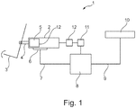
- FIG. 1 is a schematic diagram of an electro-hydraulic clutch actuation system shown, which is also referred to as a clutch-by-wire system.
- the electrohydraulic Clutch actuation system 1 comprises a pedal simulator 2 which is mechanically connected to a clutch pedal 3.
- the clutch pedal 3 actuates via a piston rod 4 a, in the pedal simulator 2 axially movably mounted piston 5.
- the movement of the piston 5 is detected by a displacement sensor unit 6, which is connected to the pedal simulator 2 and preferably integrated in this. Via an electrical line 7, the distance sensor unit 6 is connected to a control and power unit 8.
- the control and power unit 8 comprises an actuator, which controls the clutch 10 via a further line 9.
- the line 9 is formed in the present case as a hydraulic line.
- the control of the clutch 10 may alternatively but also be pneumatic or mechanical.
- the control and power unit 8 is electrically connected to a fluid control unit 11, which controls an actuator 12, which leads to the pedal simulator 2.
- FIG. 2 an embodiment of the pedal simulator 2 is shown as this in the clutch actuation system 1 according to FIG. 1 is used.
- the clutch pedal 3 is fastened to the piston rod 4 via a connection 13.
- the piston 5 is moved axially via the piston rod 4 as a function of the position of the clutch pedal 3.
- the cylinder 14 has at one end a guide element, for example a seal or a wall opening, in which the piston rod 4 is mounted axially.
- the piston 5 is connected to this and guided circumferentially on a cylinder inner wall.
- a round resistance element 15 is arranged approximately centrally, which divides the interior of the cylinder 14 into two cavities 16, 17.
- the piston 5 thereby moves axially in the first cavity 16 of the cylinder 14.
- the resistance element 15 has an opening 18 which has a variable diameter which is changed upon actuation of the clutch pedal 3.
- a separating piston 19 is disposed in the second cavity 17, which is also slidably mounted axially movable on the cylinder 14 and abuts an inner wall 21 of the cylinder 14 via an inner spring 20.
- the cavities 16 and 17 are filled with a hydraulic fluid.
- a pressure valve 22 bypassing the resistance element 15 and located outside the cylinder 14 interconnects the cavities 16, 17 with the pressure valve 22 being arranged to be closed when the hydraulic fluid from the first cavity 16 passes through the piston 5 is pressed into the second cavity 17.
- This pressure valve 22 is opened when the hydraulic fluid from the second cavity 16 flows back into the first cavity 15.
- a return spring 23 is partially arranged to the piston rod 4 and the cylinder 14.
- the resistance element 15 is closer in Fig. 3 shown.
- the resistance element 15 has a flexible boundary 24 which consists of a membrane 25 which encloses a chamber 26.
- a further liquid preferably a hydraulic fluid, is arranged, which is conveyed by the actuator 12 via a fluid line 27 into the chamber 26.
- the actuator 12 is driven by the liquid control unit 11, which is for example a motor, while the actuator 12 is advantageously designed as a piston.
- the described pedal simulator works as follows: Upon actuation of the clutch pedal 3, the pedal movement is converted via the connection 13 into a corresponding advancing movement of the piston rod 4.
- the return spring 23 is compressed and tensioned, whereby a restoring reaction force is formed.
- the piston 5 attached to the piston rod 4 is moved forward relative to the stationary mounted cylinder 14 within this.
- the control and power unit 8 determines, from a period in which the actuator 3 travels a predetermined distance, the operation speed, which is output to the fluid control unit 11.
- the actuator 12 pumps fluid into the chamber 26 in response to the operating speed of the clutch pedal 3 and causes expansion of the diaphragm 25, which adjusts an optimal constriction of the port 18.
- the hydraulic fluid flows along the constriction, which causes a reduction in the volume flowed through by the first hydraulic fluid and thus by the dimensions of the constriction of the opening 18 and the flow-dependent change in the pressure conditions in the interior of the cylinder 14.
- the resistance element 15 with the stretchable boundary 24, which allows a variable cross-section of the opening 18, may alternatively be provided with an iris of variable cross section, e.g. can be controlled with an electric, pneumatic or piezoelectric actuator.
- the described pedal simulator 2 is intended for a non-hydraulic actuation system, in particular a purely electrical vehicle coupling system. Alternatively, however, it can also be used for any other actuation systems, such as brake systems, for example, which may also have any other actuation element instead of a pedal.
Landscapes
- Engineering & Computer Science (AREA)
- Transportation (AREA)
- Mechanical Engineering (AREA)
- Physics & Mathematics (AREA)
- Fluid Mechanics (AREA)
- General Physics & Mathematics (AREA)
- Automation & Control Theory (AREA)
- Arrangement And Mounting Of Devices That Control Transmission Of Motive Force (AREA)
- Hydraulic Clutches, Magnetic Clutches, Fluid Clutches, And Fluid Joints (AREA)
- Regulating Braking Force (AREA)
- Mechanical Operated Clutches (AREA)
- Mechanical Control Devices (AREA)
Claims (9)
- Dispositif destiné à simuler l'application d'une force à un élément d'actionnement d'un véhicule, de préférence un simulateur de pédale, qui transmet une réponse tactile par un comportement force-course prédéterminé, comprenant une unité piston-cylindre (5, 14), dans lequel un piston (5) est relié par une tige de piston (4) à l'élément d'actionnement (3), qui déplace le piston (5) axialement à l'intérieur du cylindre (14), dans lequel un élément de résistance (15) pénètre radialement dans le cylindre (14) et divise le cylindre (14) en deux cavités (16, 17), qui sont toutes les deux remplies avec un milieu, dans lequel le milieu est comprimé par le piston (5) de la première cavité (16) dans la seconde cavité (17), dans lequel l'élément de résistance (15) est approximativement rond et présente une ouverture (18) de diamètre variable, qui varie en fonction de la vitesse d'actionnement de l'élément d'actionnement (3), le milieu étant ainsi comprimé avec un volume variable par le piston (5) de la première cavité (16) dans la seconde cavité (17), caractérisé en ce que l'élément de résistance (15) présente une limitation déformable (24) entourant l'ouverture (18), qui entoure une chambre (26) pouvant être remplie avec une quantité variable de liquide, pour le réglage du diamètre de l'ouverture (18) afin de faire varier la section transversale d'écoulement.
- Dispositif selon la revendication 1, caractérisé en ce que la limitation déformable (24) est réalisée sous la forme d'une membrane (25), qui entoure la chambre (26) remplie du liquide, qui peut être remplie avec le liquide par l'intermédiaire d'une conduite de liquide (27) menée à travers l'élément de résistance (15) en fonction de la vitesse d'actionnement de l'élément d'actionnement (3).
- Dispositif selon la revendication 1 ou 2, caractérisé en ce qu'un organe de réglage (12) commandé par une commande de liquide (11) pompe le liquide dans la chambre (26) en fonction de la vitesse d'actionnement, ce qui permet de changer une déformation de la membrane (25) et ainsi de régler une augmentation ou une diminution du diamètre de l'ouverture (18) de l'élément de résistance (15).
- Dispositif selon la revendication 3, caractérisé en ce que l'unité de commande de liquide (11) est disposée à l'extérieur du cylindre (14).
- Dispositif selon au moins une des revendications précédentes, caractérisé en ce qu'un piston de séparation (19) est positionné dans la seconde cavité (17) sur un côté du cylindre (14) opposé au piston (5), et agit par un élément de ressort (20) sur une paroi intérieure (21) du cylindre (14).
- Dispositif selon au moins une des revendications précédentes, caractérisé en ce que la première (16) et la seconde (17) cavités sont raccordées l'une à l'autre par une soupape de pression (22) disposée à l'extérieur du cylindre (14), dans lequel la soupape de pression (22) s'ouvre lorsque le milieu de préférence incompressible s'écoule de la seconde cavité (17) à la première cavité (16) et se ferme lorsque le milieu s'écoule de la première cavité (16) à la seconde cavité (17).
- Dispositif selon au moins une des revendications précédentes, caractérisé en ce que la tige de piston (4) et le cylindre (14) sont reliés au moins en partie par un ressort de rappel (23).
- Dispositif permettant d'actionner un système d'embrayage électrique, dans lequel un élément d'actionnement (3) est relié à un dispositif (2) destiné à simuler l'application d'une force à l'élément d'actionnement (3), dans lequel la position de l'élément d'actionnement (3) est détectée par une unité de capteur (6) et est retransmise électriquement à une unité de commande (8), qui est en liaison active avec un embrayage (10), caractérisé en ce que le dispositif (2) destiné à simuler l'application d'une force est réalisé selon au moins une des revendications précédentes 1 à 7.
- Dispositif selon la revendication 8, caractérisé en ce que l'unité de commande (8) est raccordée à une limitation déformable (24) de l'élément de résistance (15) par une unité de commande de liquide (11), qui commande un organe de réglage hydraulique (12).
Applications Claiming Priority (2)
| Application Number | Priority Date | Filing Date | Title |
|---|---|---|---|
| DE102014207983 | 2014-04-29 | ||
| PCT/DE2015/200218 WO2015165453A2 (fr) | 2014-04-29 | 2015-03-31 | Dispositif destiné à simuler l'application d'une force sur un élément d'actionnement d'un véhicule, de préférence simulateur de pédale, et dispositif permettant d'actionner un système d'embrayage électrique |
Publications (2)
| Publication Number | Publication Date |
|---|---|
| EP3137784A2 EP3137784A2 (fr) | 2017-03-08 |
| EP3137784B1 true EP3137784B1 (fr) | 2018-11-14 |
Family
ID=53491244
Family Applications (1)
| Application Number | Title | Priority Date | Filing Date |
|---|---|---|---|
| EP15732154.8A Not-in-force EP3137784B1 (fr) | 2014-04-29 | 2015-03-31 | Dispositif destiné à simuler l'application d'une force sur un élément d'actionnement d'un véhicule, de préférence simulateur de pédale, et dispositif permettant d'actionner un système d'embrayage électrique |
Country Status (4)
| Country | Link |
|---|---|
| EP (1) | EP3137784B1 (fr) |
| JP (1) | JP2017520445A (fr) |
| DE (1) | DE112015002076A5 (fr) |
| WO (1) | WO2015165453A2 (fr) |
Families Citing this family (3)
| Publication number | Priority date | Publication date | Assignee | Title |
|---|---|---|---|---|
| DE102015015614A1 (de) * | 2015-12-03 | 2017-06-08 | Audi Ag | Verfahren zum Betreiben eines Bremskraftsimulators sowie entsprechender Bremskraftsimulator |
| US10359802B2 (en) | 2016-08-22 | 2019-07-23 | Cts Corporation | Variable force electronic vehicle clutch pedal |
| DE102020204106A1 (de) * | 2020-03-30 | 2021-09-30 | Continental Teves Ag & Co. Ohg | Rückstellvorrichtung für eine Bremsbetätigungseinheit und Bremsbetätigungseinheit |
Family Cites Families (10)
| Publication number | Priority date | Publication date | Assignee | Title |
|---|---|---|---|---|
| JPS6154561U (fr) * | 1984-09-13 | 1986-04-12 | ||
| JP3771672B2 (ja) * | 1997-05-27 | 2006-04-26 | 曙ブレーキ工業株式会社 | ブレーキペダル操作検出装置 |
| JP2001151091A (ja) * | 1999-11-25 | 2001-06-05 | Bosch Braking Systems Co Ltd | 電気制御ブレーキシステム |
| DE10016879A1 (de) * | 2000-04-05 | 2001-10-18 | Bayerische Motoren Werke Ag | Betätigungseinrichtung für eine Kraftfahrzeug-Bremsanlage vom Typ "brake by wire" |
| DE10039670A1 (de) * | 2000-08-14 | 2002-03-07 | Lucas Varity Gmbh | Pedalsimulationsvorrichtung |
| JP2005214370A (ja) * | 2004-02-02 | 2005-08-11 | Nissan Motor Co Ltd | 車両用パワートレインの制御装置 |
| JP2009222068A (ja) * | 2008-03-13 | 2009-10-01 | Aisin Seiki Co Ltd | クラッチバイワイヤシステム |
| JP5767793B2 (ja) * | 2010-08-31 | 2015-08-19 | 株式会社エー・シー・イー | 排気圧力/流量コントローラ |
| DE102010061439A1 (de) | 2010-12-21 | 2012-06-21 | Dr. Ing. H.C. F. Porsche Aktiengesellschaft | Bremssystem für ein Kraftfahrzeug |
| DE102011016239A1 (de) * | 2011-04-06 | 2012-10-11 | Volkswagen Ag | Pedalkraftsimulator für eine Fahrzeugbremsanlage |
-
2015
- 2015-03-31 DE DE112015002076.4T patent/DE112015002076A5/de not_active Withdrawn
- 2015-03-31 EP EP15732154.8A patent/EP3137784B1/fr not_active Not-in-force
- 2015-03-31 JP JP2016565243A patent/JP2017520445A/ja active Pending
- 2015-03-31 WO PCT/DE2015/200218 patent/WO2015165453A2/fr active Application Filing
Non-Patent Citations (1)
| Title |
|---|
| None * |
Also Published As
| Publication number | Publication date |
|---|---|
| JP2017520445A (ja) | 2017-07-27 |
| WO2015165453A2 (fr) | 2015-11-05 |
| EP3137784A2 (fr) | 2017-03-08 |
| DE112015002076A5 (de) | 2017-03-09 |
| WO2015165453A3 (fr) | 2016-01-14 |
Similar Documents
| Publication | Publication Date | Title |
|---|---|---|
| EP2379377B1 (fr) | Fonctionnement d'un servofrein en tant que simulateur de pédale, et servofrein configuré de manière correspondante | |
| EP3213168B2 (fr) | Dispositif permettant de simuler l'application d'une force sur un élément d'actionnement d'un véhicule, sous la forme d'un simulateur de pédale | |
| EP1233891B2 (fr) | Simulateur pour systeme d'actionnement non hydraulique | |
| EP2896539B1 (fr) | Système destiné à simuler la force de pédalage, en particulier pour un système d'actionnement d'embrayage | |
| DE102009057238A1 (de) | Regenerative Bremsbetätigungsvorrichtung | |
| EP3137351B1 (fr) | Dispositif de simulation de force pour un élément de service, de préférence un simulateur de pedal, et arrangement pour activer un système d'embrayage électrique | |
| DE102015220669A1 (de) | Vorrichtung zur Kraftsimulation an einem Betätigungselement eines Fahrzeuges und eine Einrichtung zur Betätigung eines elektrischen Kupplungssystems, vorzugsweise eines Fahrzeuges | |
| DE102006030846A1 (de) | Pneumatischer Pedalsimulator | |
| DE102014110300A1 (de) | Pedalkraftsimulator und Bremsanlage | |
| DE10039670A1 (de) | Pedalsimulationsvorrichtung | |
| EP3137350B1 (fr) | Dispositif de simulation de force pour un élément de service, de préférence un simulateur de pedal, et arrangement pour activer un système d'embrayage électrique | |
| EP3137784B1 (fr) | Dispositif destiné à simuler l'application d'une force sur un élément d'actionnement d'un véhicule, de préférence simulateur de pédale, et dispositif permettant d'actionner un système d'embrayage électrique | |
| DE102011117264A1 (de) | Bremspedalsimulator | |
| WO2015165450A1 (fr) | Dispositif destiné à simuler l'application d'une force sur un élément d'actionnement d'un véhicule, de préférence simulateur de pédale, et dispositif permettant d'actionner un système d'embrayage électrique | |
| WO2015165449A1 (fr) | Dispositif permettant de simuler l'application d'une force sur un élément d'actionnement d'un véhicule, de préférence simulateur de pédale | |
| WO2013120562A1 (fr) | Dispositif de freinage d'un véhicule et procédé permettant de faire fonctionner un dispositif de freinage d'un véhicule | |
| DE102014217327A1 (de) | Aktives Fahrpedal mit Freiweg | |
| EP2927062B1 (fr) | Dispositif de simulation de force de pédalage | |
| DE102011121749A1 (de) | Vorrichtung zur Erzeugung einer Gegenkraft an einem Pedal | |
| DE102010021935A1 (de) | Bremspedalsimulator und Bremssystem | |
| DE102012202314A1 (de) | Kraft-Weg-Simulation für Pedal | |
| DE102005044300A1 (de) | Vorrichtung zur Betätigung einer Kupplung | |
| DE102018211524A1 (de) | Einrichtung zur Variation des Pedalgefühls in einem Bremsregelsystem eines Kraftfahrzeugs | |
| DE102020211084A1 (de) | Vorrichtung zur Erzeugung einer Gegenkraft auf ein Bremspedal und Kraftfahrzeug | |
| WO2019137657A1 (fr) | Servofrein et procédé de fabrication d'un servofrein |
Legal Events
| Date | Code | Title | Description |
|---|---|---|---|
| STAA | Information on the status of an ep patent application or granted ep patent |
Free format text: STATUS: THE INTERNATIONAL PUBLICATION HAS BEEN MADE |
|
| PUAI | Public reference made under article 153(3) epc to a published international application that has entered the european phase |
Free format text: ORIGINAL CODE: 0009012 |
|
| STAA | Information on the status of an ep patent application or granted ep patent |
Free format text: STATUS: REQUEST FOR EXAMINATION WAS MADE |
|
| 17P | Request for examination filed |
Effective date: 20161129 |
|
| AK | Designated contracting states |
Kind code of ref document: A2 Designated state(s): AL AT BE BG CH CY CZ DE DK EE ES FI FR GB GR HR HU IE IS IT LI LT LU LV MC MK MT NL NO PL PT RO RS SE SI SK SM TR |
|
| AX | Request for extension of the european patent |
Extension state: BA ME |
|
| DAV | Request for validation of the european patent (deleted) | ||
| DAX | Request for extension of the european patent (deleted) | ||
| STAA | Information on the status of an ep patent application or granted ep patent |
Free format text: STATUS: EXAMINATION IS IN PROGRESS |
|
| 17Q | First examination report despatched |
Effective date: 20170830 |
|
| GRAP | Despatch of communication of intention to grant a patent |
Free format text: ORIGINAL CODE: EPIDOSNIGR1 |
|
| STAA | Information on the status of an ep patent application or granted ep patent |
Free format text: STATUS: GRANT OF PATENT IS INTENDED |
|
| INTG | Intention to grant announced |
Effective date: 20180216 |
|
| GRAS | Grant fee paid |
Free format text: ORIGINAL CODE: EPIDOSNIGR3 |
|
| GRAA | (expected) grant |
Free format text: ORIGINAL CODE: 0009210 |
|
| STAA | Information on the status of an ep patent application or granted ep patent |
Free format text: STATUS: THE PATENT HAS BEEN GRANTED |
|
| AK | Designated contracting states |
Kind code of ref document: B1 Designated state(s): AL AT BE BG CH CY CZ DE DK EE ES FI FR GB GR HR HU IE IS IT LI LT LU LV MC MK MT NL NO PL PT RO RS SE SI SK SM TR |
|
| REG | Reference to a national code |
Ref country code: CH Ref legal event code: EP Ref country code: AT Ref legal event code: REF Ref document number: 1065198 Country of ref document: AT Kind code of ref document: T Effective date: 20181115 |
|
| REG | Reference to a national code |
Ref country code: DE Ref legal event code: R096 Ref document number: 502015006882 Country of ref document: DE |
|
| REG | Reference to a national code |
Ref country code: IE Ref legal event code: FG4D Free format text: LANGUAGE OF EP DOCUMENT: GERMAN |
|
| REG | Reference to a national code |
Ref country code: CH Ref legal event code: PK Free format text: BERICHTIGUNGEN |
|
| RIC2 | Information provided on ipc code assigned after grant |
Ipc: B60T 8/40 20060101ALI20161007BHEP Ipc: G05G 1/30 20080401ALI20161007BHEP Ipc: F16D 48/06 20060101AFI20161007BHEP Ipc: G05G 5/03 20080401ALI20161007BHEP Ipc: B60T 11/16 20060101ALI20161007BHEP |
|
| REG | Reference to a national code |
Ref country code: NL Ref legal event code: MP Effective date: 20181114 |
|
| REG | Reference to a national code |
Ref country code: LT Ref legal event code: MG4D |
|
| PG25 | Lapsed in a contracting state [announced via postgrant information from national office to epo] |
Ref country code: IS Free format text: LAPSE BECAUSE OF FAILURE TO SUBMIT A TRANSLATION OF THE DESCRIPTION OR TO PAY THE FEE WITHIN THE PRESCRIBED TIME-LIMIT Effective date: 20190314 Ref country code: FI Free format text: LAPSE BECAUSE OF FAILURE TO SUBMIT A TRANSLATION OF THE DESCRIPTION OR TO PAY THE FEE WITHIN THE PRESCRIBED TIME-LIMIT Effective date: 20181114 Ref country code: NO Free format text: LAPSE BECAUSE OF FAILURE TO SUBMIT A TRANSLATION OF THE DESCRIPTION OR TO PAY THE FEE WITHIN THE PRESCRIBED TIME-LIMIT Effective date: 20190214 Ref country code: ES Free format text: LAPSE BECAUSE OF FAILURE TO SUBMIT A TRANSLATION OF THE DESCRIPTION OR TO PAY THE FEE WITHIN THE PRESCRIBED TIME-LIMIT Effective date: 20181114 Ref country code: LV Free format text: LAPSE BECAUSE OF FAILURE TO SUBMIT A TRANSLATION OF THE DESCRIPTION OR TO PAY THE FEE WITHIN THE PRESCRIBED TIME-LIMIT Effective date: 20181114 Ref country code: LT Free format text: LAPSE BECAUSE OF FAILURE TO SUBMIT A TRANSLATION OF THE DESCRIPTION OR TO PAY THE FEE WITHIN THE PRESCRIBED TIME-LIMIT Effective date: 20181114 Ref country code: HR Free format text: LAPSE BECAUSE OF FAILURE TO SUBMIT A TRANSLATION OF THE DESCRIPTION OR TO PAY THE FEE WITHIN THE PRESCRIBED TIME-LIMIT Effective date: 20181114 Ref country code: BG Free format text: LAPSE BECAUSE OF FAILURE TO SUBMIT A TRANSLATION OF THE DESCRIPTION OR TO PAY THE FEE WITHIN THE PRESCRIBED TIME-LIMIT Effective date: 20190214 |
|
| PG25 | Lapsed in a contracting state [announced via postgrant information from national office to epo] |
Ref country code: AL Free format text: LAPSE BECAUSE OF FAILURE TO SUBMIT A TRANSLATION OF THE DESCRIPTION OR TO PAY THE FEE WITHIN THE PRESCRIBED TIME-LIMIT Effective date: 20181114 Ref country code: PT Free format text: LAPSE BECAUSE OF FAILURE TO SUBMIT A TRANSLATION OF THE DESCRIPTION OR TO PAY THE FEE WITHIN THE PRESCRIBED TIME-LIMIT Effective date: 20190314 Ref country code: NL Free format text: LAPSE BECAUSE OF FAILURE TO SUBMIT A TRANSLATION OF THE DESCRIPTION OR TO PAY THE FEE WITHIN THE PRESCRIBED TIME-LIMIT Effective date: 20181114 Ref country code: SE Free format text: LAPSE BECAUSE OF FAILURE TO SUBMIT A TRANSLATION OF THE DESCRIPTION OR TO PAY THE FEE WITHIN THE PRESCRIBED TIME-LIMIT Effective date: 20181114 Ref country code: GR Free format text: LAPSE BECAUSE OF FAILURE TO SUBMIT A TRANSLATION OF THE DESCRIPTION OR TO PAY THE FEE WITHIN THE PRESCRIBED TIME-LIMIT Effective date: 20190215 Ref country code: RS Free format text: LAPSE BECAUSE OF FAILURE TO SUBMIT A TRANSLATION OF THE DESCRIPTION OR TO PAY THE FEE WITHIN THE PRESCRIBED TIME-LIMIT Effective date: 20181114 |
|
| PG25 | Lapsed in a contracting state [announced via postgrant information from national office to epo] |
Ref country code: IT Free format text: LAPSE BECAUSE OF FAILURE TO SUBMIT A TRANSLATION OF THE DESCRIPTION OR TO PAY THE FEE WITHIN THE PRESCRIBED TIME-LIMIT Effective date: 20181114 Ref country code: CZ Free format text: LAPSE BECAUSE OF FAILURE TO SUBMIT A TRANSLATION OF THE DESCRIPTION OR TO PAY THE FEE WITHIN THE PRESCRIBED TIME-LIMIT Effective date: 20181114 Ref country code: PL Free format text: LAPSE BECAUSE OF FAILURE TO SUBMIT A TRANSLATION OF THE DESCRIPTION OR TO PAY THE FEE WITHIN THE PRESCRIBED TIME-LIMIT Effective date: 20181114 Ref country code: DK Free format text: LAPSE BECAUSE OF FAILURE TO SUBMIT A TRANSLATION OF THE DESCRIPTION OR TO PAY THE FEE WITHIN THE PRESCRIBED TIME-LIMIT Effective date: 20181114 |
|
| REG | Reference to a national code |
Ref country code: DE Ref legal event code: R097 Ref document number: 502015006882 Country of ref document: DE |
|
| PG25 | Lapsed in a contracting state [announced via postgrant information from national office to epo] |
Ref country code: SM Free format text: LAPSE BECAUSE OF FAILURE TO SUBMIT A TRANSLATION OF THE DESCRIPTION OR TO PAY THE FEE WITHIN THE PRESCRIBED TIME-LIMIT Effective date: 20181114 Ref country code: EE Free format text: LAPSE BECAUSE OF FAILURE TO SUBMIT A TRANSLATION OF THE DESCRIPTION OR TO PAY THE FEE WITHIN THE PRESCRIBED TIME-LIMIT Effective date: 20181114 Ref country code: SK Free format text: LAPSE BECAUSE OF FAILURE TO SUBMIT A TRANSLATION OF THE DESCRIPTION OR TO PAY THE FEE WITHIN THE PRESCRIBED TIME-LIMIT Effective date: 20181114 Ref country code: RO Free format text: LAPSE BECAUSE OF FAILURE TO SUBMIT A TRANSLATION OF THE DESCRIPTION OR TO PAY THE FEE WITHIN THE PRESCRIBED TIME-LIMIT Effective date: 20181114 |
|
| PLBE | No opposition filed within time limit |
Free format text: ORIGINAL CODE: 0009261 |
|
| STAA | Information on the status of an ep patent application or granted ep patent |
Free format text: STATUS: NO OPPOSITION FILED WITHIN TIME LIMIT |
|
| 26N | No opposition filed |
Effective date: 20190815 |
|
| PG25 | Lapsed in a contracting state [announced via postgrant information from national office to epo] |
Ref country code: MC Free format text: LAPSE BECAUSE OF FAILURE TO SUBMIT A TRANSLATION OF THE DESCRIPTION OR TO PAY THE FEE WITHIN THE PRESCRIBED TIME-LIMIT Effective date: 20181114 Ref country code: SI Free format text: LAPSE BECAUSE OF FAILURE TO SUBMIT A TRANSLATION OF THE DESCRIPTION OR TO PAY THE FEE WITHIN THE PRESCRIBED TIME-LIMIT Effective date: 20181114 |
|
| REG | Reference to a national code |
Ref country code: CH Ref legal event code: PL |
|
| GBPC | Gb: european patent ceased through non-payment of renewal fee |
Effective date: 20190331 |
|
| PG25 | Lapsed in a contracting state [announced via postgrant information from national office to epo] |
Ref country code: LU Free format text: LAPSE BECAUSE OF NON-PAYMENT OF DUE FEES Effective date: 20190331 |
|
| REG | Reference to a national code |
Ref country code: BE Ref legal event code: MM Effective date: 20190331 |
|
| PG25 | Lapsed in a contracting state [announced via postgrant information from national office to epo] |
Ref country code: CH Free format text: LAPSE BECAUSE OF NON-PAYMENT OF DUE FEES Effective date: 20190331 Ref country code: GB Free format text: LAPSE BECAUSE OF NON-PAYMENT OF DUE FEES Effective date: 20190331 Ref country code: LI Free format text: LAPSE BECAUSE OF NON-PAYMENT OF DUE FEES Effective date: 20190331 Ref country code: IE Free format text: LAPSE BECAUSE OF NON-PAYMENT OF DUE FEES Effective date: 20190331 |
|
| PG25 | Lapsed in a contracting state [announced via postgrant information from national office to epo] |
Ref country code: BE Free format text: LAPSE BECAUSE OF NON-PAYMENT OF DUE FEES Effective date: 20190331 |
|
| PG25 | Lapsed in a contracting state [announced via postgrant information from national office to epo] |
Ref country code: TR Free format text: LAPSE BECAUSE OF FAILURE TO SUBMIT A TRANSLATION OF THE DESCRIPTION OR TO PAY THE FEE WITHIN THE PRESCRIBED TIME-LIMIT Effective date: 20181114 |
|
| PG25 | Lapsed in a contracting state [announced via postgrant information from national office to epo] |
Ref country code: MT Free format text: LAPSE BECAUSE OF FAILURE TO SUBMIT A TRANSLATION OF THE DESCRIPTION OR TO PAY THE FEE WITHIN THE PRESCRIBED TIME-LIMIT Effective date: 20181114 |
|
| REG | Reference to a national code |
Ref country code: AT Ref legal event code: MM01 Ref document number: 1065198 Country of ref document: AT Kind code of ref document: T Effective date: 20200331 |
|
| PG25 | Lapsed in a contracting state [announced via postgrant information from national office to epo] |
Ref country code: CY Free format text: LAPSE BECAUSE OF FAILURE TO SUBMIT A TRANSLATION OF THE DESCRIPTION OR TO PAY THE FEE WITHIN THE PRESCRIBED TIME-LIMIT Effective date: 20181114 |
|
| PG25 | Lapsed in a contracting state [announced via postgrant information from national office to epo] |
Ref country code: HU Free format text: LAPSE BECAUSE OF FAILURE TO SUBMIT A TRANSLATION OF THE DESCRIPTION OR TO PAY THE FEE WITHIN THE PRESCRIBED TIME-LIMIT; INVALID AB INITIO Effective date: 20150331 |
|
| PG25 | Lapsed in a contracting state [announced via postgrant information from national office to epo] |
Ref country code: AT Free format text: LAPSE BECAUSE OF NON-PAYMENT OF DUE FEES Effective date: 20200331 |
|
| PGFP | Annual fee paid to national office [announced via postgrant information from national office to epo] |
Ref country code: FR Payment date: 20220322 Year of fee payment: 8 |
|
| PG25 | Lapsed in a contracting state [announced via postgrant information from national office to epo] |
Ref country code: MK Free format text: LAPSE BECAUSE OF FAILURE TO SUBMIT A TRANSLATION OF THE DESCRIPTION OR TO PAY THE FEE WITHIN THE PRESCRIBED TIME-LIMIT Effective date: 20181114 |
|
| PGFP | Annual fee paid to national office [announced via postgrant information from national office to epo] |
Ref country code: DE Payment date: 20220519 Year of fee payment: 8 |
|
| P01 | Opt-out of the competence of the unified patent court (upc) registered |
Effective date: 20230523 |
|
| REG | Reference to a national code |
Ref country code: DE Ref legal event code: R119 Ref document number: 502015006882 Country of ref document: DE |
|
| PG25 | Lapsed in a contracting state [announced via postgrant information from national office to epo] |
Ref country code: FR Free format text: LAPSE BECAUSE OF NON-PAYMENT OF DUE FEES Effective date: 20230331 Ref country code: DE Free format text: LAPSE BECAUSE OF NON-PAYMENT OF DUE FEES Effective date: 20231003 |