EP3137663B1 - Mikroperforierte rückstrahlende textilhülle und konstruktionsverfahren dafür - Google Patents
Mikroperforierte rückstrahlende textilhülle und konstruktionsverfahren dafür Download PDFInfo
- Publication number
- EP3137663B1 EP3137663B1 EP15722395.9A EP15722395A EP3137663B1 EP 3137663 B1 EP3137663 B1 EP 3137663B1 EP 15722395 A EP15722395 A EP 15722395A EP 3137663 B1 EP3137663 B1 EP 3137663B1
- Authority
- EP
- European Patent Office
- Prior art keywords
- micro
- further including
- inner textile
- sleeve
- textile wall
- Prior art date
- Legal status (The legal status is an assumption and is not a legal conclusion. Google has not performed a legal analysis and makes no representation as to the accuracy of the status listed.)
- Active
Links
Images
Classifications
-
- B—PERFORMING OPERATIONS; TRANSPORTING
- B32—LAYERED PRODUCTS
- B32B—LAYERED PRODUCTS, i.e. PRODUCTS BUILT-UP OF STRATA OF FLAT OR NON-FLAT, e.g. CELLULAR OR HONEYCOMB, FORM
- B32B1/00—Layered products having a non-planar shape
- B32B1/08—Tubular products
-
- B—PERFORMING OPERATIONS; TRANSPORTING
- B32—LAYERED PRODUCTS
- B32B—LAYERED PRODUCTS, i.e. PRODUCTS BUILT-UP OF STRATA OF FLAT OR NON-FLAT, e.g. CELLULAR OR HONEYCOMB, FORM
- B32B5/00—Layered products characterised by the non- homogeneity or physical structure, i.e. comprising a fibrous, filamentary, particulate or foam layer; Layered products characterised by having a layer differing constitutionally or physically in different parts
- B32B5/02—Layered products characterised by the non- homogeneity or physical structure, i.e. comprising a fibrous, filamentary, particulate or foam layer; Layered products characterised by having a layer differing constitutionally or physically in different parts characterised by structural features of a fibrous or filamentary layer
- B32B5/022—Non-woven fabric
-
- B—PERFORMING OPERATIONS; TRANSPORTING
- B32—LAYERED PRODUCTS
- B32B—LAYERED PRODUCTS, i.e. PRODUCTS BUILT-UP OF STRATA OF FLAT OR NON-FLAT, e.g. CELLULAR OR HONEYCOMB, FORM
- B32B15/00—Layered products comprising a layer of metal
- B32B15/14—Layered products comprising a layer of metal next to a fibrous or filamentary layer
-
- B—PERFORMING OPERATIONS; TRANSPORTING
- B32—LAYERED PRODUCTS
- B32B—LAYERED PRODUCTS, i.e. PRODUCTS BUILT-UP OF STRATA OF FLAT OR NON-FLAT, e.g. CELLULAR OR HONEYCOMB, FORM
- B32B3/00—Layered products comprising a layer with external or internal discontinuities or unevennesses, or a layer of non-planar shape; Layered products comprising a layer having particular features of form
- B32B3/26—Layered products comprising a layer with external or internal discontinuities or unevennesses, or a layer of non-planar shape; Layered products comprising a layer having particular features of form characterised by a particular shape of the outline of the cross-section of a continuous layer; characterised by a layer with cavities or internal voids ; characterised by an apertured layer
- B32B3/266—Layered products comprising a layer with external or internal discontinuities or unevennesses, or a layer of non-planar shape; Layered products comprising a layer having particular features of form characterised by a particular shape of the outline of the cross-section of a continuous layer; characterised by a layer with cavities or internal voids ; characterised by an apertured layer characterised by an apertured layer, the apertures going through the whole thickness of the layer, e.g. expanded metal, perforated layer, slit layer regular cells B32B3/12
-
- B—PERFORMING OPERATIONS; TRANSPORTING
- B32—LAYERED PRODUCTS
- B32B—LAYERED PRODUCTS, i.e. PRODUCTS BUILT-UP OF STRATA OF FLAT OR NON-FLAT, e.g. CELLULAR OR HONEYCOMB, FORM
- B32B37/00—Methods or apparatus for laminating, e.g. by curing or by ultrasonic bonding
- B32B37/14—Methods or apparatus for laminating, e.g. by curing or by ultrasonic bonding characterised by the properties of the layers
- B32B37/142—Laminating of sheets, panels or inserts, e.g. stiffeners, by wrapping in at least one outer layer, or inserting into a preformed pocket
-
- B—PERFORMING OPERATIONS; TRANSPORTING
- B32—LAYERED PRODUCTS
- B32B—LAYERED PRODUCTS, i.e. PRODUCTS BUILT-UP OF STRATA OF FLAT OR NON-FLAT, e.g. CELLULAR OR HONEYCOMB, FORM
- B32B37/00—Methods or apparatus for laminating, e.g. by curing or by ultrasonic bonding
- B32B37/14—Methods or apparatus for laminating, e.g. by curing or by ultrasonic bonding characterised by the properties of the layers
- B32B37/16—Methods or apparatus for laminating, e.g. by curing or by ultrasonic bonding characterised by the properties of the layers with all layers existing as coherent layers before laminating
- B32B37/18—Methods or apparatus for laminating, e.g. by curing or by ultrasonic bonding characterised by the properties of the layers with all layers existing as coherent layers before laminating involving the assembly of discrete sheets or panels only
-
- B—PERFORMING OPERATIONS; TRANSPORTING
- B32—LAYERED PRODUCTS
- B32B—LAYERED PRODUCTS, i.e. PRODUCTS BUILT-UP OF STRATA OF FLAT OR NON-FLAT, e.g. CELLULAR OR HONEYCOMB, FORM
- B32B5/00—Layered products characterised by the non- homogeneity or physical structure, i.e. comprising a fibrous, filamentary, particulate or foam layer; Layered products characterised by having a layer differing constitutionally or physically in different parts
- B32B5/02—Layered products characterised by the non- homogeneity or physical structure, i.e. comprising a fibrous, filamentary, particulate or foam layer; Layered products characterised by having a layer differing constitutionally or physically in different parts characterised by structural features of a fibrous or filamentary layer
- B32B5/026—Knitted fabric
-
- B—PERFORMING OPERATIONS; TRANSPORTING
- B32—LAYERED PRODUCTS
- B32B—LAYERED PRODUCTS, i.e. PRODUCTS BUILT-UP OF STRATA OF FLAT OR NON-FLAT, e.g. CELLULAR OR HONEYCOMB, FORM
- B32B5/00—Layered products characterised by the non- homogeneity or physical structure, i.e. comprising a fibrous, filamentary, particulate or foam layer; Layered products characterised by having a layer differing constitutionally or physically in different parts
- B32B5/22—Layered products characterised by the non- homogeneity or physical structure, i.e. comprising a fibrous, filamentary, particulate or foam layer; Layered products characterised by having a layer differing constitutionally or physically in different parts characterised by the presence of two or more layers which are next to each other and are fibrous, filamentary, formed of particles or foamed
- B32B5/24—Layered products characterised by the non- homogeneity or physical structure, i.e. comprising a fibrous, filamentary, particulate or foam layer; Layered products characterised by having a layer differing constitutionally or physically in different parts characterised by the presence of two or more layers which are next to each other and are fibrous, filamentary, formed of particles or foamed one layer being a fibrous or filamentary layer
- B32B5/28—Layered products characterised by the non- homogeneity or physical structure, i.e. comprising a fibrous, filamentary, particulate or foam layer; Layered products characterised by having a layer differing constitutionally or physically in different parts characterised by the presence of two or more layers which are next to each other and are fibrous, filamentary, formed of particles or foamed one layer being a fibrous or filamentary layer impregnated with or embedded in a plastic substance
-
- D—TEXTILES; PAPER
- D03—WEAVING
- D03D—WOVEN FABRICS; METHODS OF WEAVING; LOOMS
- D03D1/00—Woven fabrics designed to make specified articles
- D03D1/0035—Protective fabrics
-
- D—TEXTILES; PAPER
- D03—WEAVING
- D03D—WOVEN FABRICS; METHODS OF WEAVING; LOOMS
- D03D1/00—Woven fabrics designed to make specified articles
- D03D1/0035—Protective fabrics
- D03D1/0043—Protective fabrics for elongated members, i.e. sleeves
-
- D—TEXTILES; PAPER
- D03—WEAVING
- D03D—WOVEN FABRICS; METHODS OF WEAVING; LOOMS
- D03D1/00—Woven fabrics designed to make specified articles
- D03D1/0035—Protective fabrics
- D03D1/0058—Electromagnetic radiation resistant
-
- D—TEXTILES; PAPER
- D03—WEAVING
- D03D—WOVEN FABRICS; METHODS OF WEAVING; LOOMS
- D03D15/00—Woven fabrics characterised by the material, structure or properties of the fibres, filaments, yarns, threads or other warp or weft elements used
- D03D15/40—Woven fabrics characterised by the material, structure or properties of the fibres, filaments, yarns, threads or other warp or weft elements used characterised by the structure of the yarns or threads
- D03D15/47—Woven fabrics characterised by the material, structure or properties of the fibres, filaments, yarns, threads or other warp or weft elements used characterised by the structure of the yarns or threads multicomponent, e.g. blended yarns or threads
-
- D—TEXTILES; PAPER
- D03—WEAVING
- D03D—WOVEN FABRICS; METHODS OF WEAVING; LOOMS
- D03D15/00—Woven fabrics characterised by the material, structure or properties of the fibres, filaments, yarns, threads or other warp or weft elements used
- D03D15/50—Woven fabrics characterised by the material, structure or properties of the fibres, filaments, yarns, threads or other warp or weft elements used characterised by the properties of the yarns or threads
- D03D15/567—Shapes or effects upon shrinkage
-
- D—TEXTILES; PAPER
- D03—WEAVING
- D03D—WOVEN FABRICS; METHODS OF WEAVING; LOOMS
- D03D15/00—Woven fabrics characterised by the material, structure or properties of the fibres, filaments, yarns, threads or other warp or weft elements used
- D03D15/50—Woven fabrics characterised by the material, structure or properties of the fibres, filaments, yarns, threads or other warp or weft elements used characterised by the properties of the yarns or threads
- D03D15/593—Stiff materials, e.g. cane or slat
-
- D—TEXTILES; PAPER
- D03—WEAVING
- D03D—WOVEN FABRICS; METHODS OF WEAVING; LOOMS
- D03D3/00—Woven fabrics characterised by their shape
- D03D3/02—Tubular fabrics
-
- F—MECHANICAL ENGINEERING; LIGHTING; HEATING; WEAPONS; BLASTING
- F16—ENGINEERING ELEMENTS AND UNITS; GENERAL MEASURES FOR PRODUCING AND MAINTAINING EFFECTIVE FUNCTIONING OF MACHINES OR INSTALLATIONS; THERMAL INSULATION IN GENERAL
- F16L—PIPES; JOINTS OR FITTINGS FOR PIPES; SUPPORTS FOR PIPES, CABLES OR PROTECTIVE TUBING; MEANS FOR THERMAL INSULATION IN GENERAL
- F16L57/00—Protection of pipes or objects of similar shape against external or internal damage or wear
- F16L57/04—Protection of pipes or objects of similar shape against external or internal damage or wear against fire or other external sources of extreme heat
-
- F—MECHANICAL ENGINEERING; LIGHTING; HEATING; WEAPONS; BLASTING
- F16—ENGINEERING ELEMENTS AND UNITS; GENERAL MEASURES FOR PRODUCING AND MAINTAINING EFFECTIVE FUNCTIONING OF MACHINES OR INSTALLATIONS; THERMAL INSULATION IN GENERAL
- F16L—PIPES; JOINTS OR FITTINGS FOR PIPES; SUPPORTS FOR PIPES, CABLES OR PROTECTIVE TUBING; MEANS FOR THERMAL INSULATION IN GENERAL
- F16L59/00—Thermal insulation in general
- F16L59/08—Means for preventing radiation, e.g. with metal foil
-
- B—PERFORMING OPERATIONS; TRANSPORTING
- B32—LAYERED PRODUCTS
- B32B—LAYERED PRODUCTS, i.e. PRODUCTS BUILT-UP OF STRATA OF FLAT OR NON-FLAT, e.g. CELLULAR OR HONEYCOMB, FORM
- B32B38/00—Ancillary operations in connection with laminating processes
- B32B38/04—Punching, slitting or perforating
- B32B2038/047—Perforating
-
- B—PERFORMING OPERATIONS; TRANSPORTING
- B32—LAYERED PRODUCTS
- B32B—LAYERED PRODUCTS, i.e. PRODUCTS BUILT-UP OF STRATA OF FLAT OR NON-FLAT, e.g. CELLULAR OR HONEYCOMB, FORM
- B32B2307/00—Properties of the layers or laminate
- B32B2307/40—Properties of the layers or laminate having particular optical properties
- B32B2307/416—Reflective
-
- B—PERFORMING OPERATIONS; TRANSPORTING
- B32—LAYERED PRODUCTS
- B32B—LAYERED PRODUCTS, i.e. PRODUCTS BUILT-UP OF STRATA OF FLAT OR NON-FLAT, e.g. CELLULAR OR HONEYCOMB, FORM
- B32B2571/00—Protective equipment
-
- B—PERFORMING OPERATIONS; TRANSPORTING
- B60—VEHICLES IN GENERAL
- B60R—VEHICLES, VEHICLE FITTINGS, OR VEHICLE PARTS, NOT OTHERWISE PROVIDED FOR
- B60R16/00—Electric or fluid circuits specially adapted for vehicles and not otherwise provided for; Arrangement of elements of electric or fluid circuits specially adapted for vehicles and not otherwise provided for
- B60R16/02—Electric or fluid circuits specially adapted for vehicles and not otherwise provided for; Arrangement of elements of electric or fluid circuits specially adapted for vehicles and not otherwise provided for electric constitutive elements
- B60R16/0207—Wire harnesses
- B60R16/0215—Protecting, fastening and routing means therefor
-
- D—TEXTILES; PAPER
- D10—INDEXING SCHEME ASSOCIATED WITH SUBLASSES OF SECTION D, RELATING TO TEXTILES
- D10B—INDEXING SCHEME ASSOCIATED WITH SUBLASSES OF SECTION D, RELATING TO TEXTILES
- D10B2101/00—Inorganic fibres
- D10B2101/20—Metallic fibres
-
- D—TEXTILES; PAPER
- D10—INDEXING SCHEME ASSOCIATED WITH SUBLASSES OF SECTION D, RELATING TO TEXTILES
- D10B—INDEXING SCHEME ASSOCIATED WITH SUBLASSES OF SECTION D, RELATING TO TEXTILES
- D10B2401/00—Physical properties
- D10B2401/04—Heat-responsive characteristics
- D10B2401/041—Heat-responsive characteristics thermoplastic; thermosetting
-
- D—TEXTILES; PAPER
- D10—INDEXING SCHEME ASSOCIATED WITH SUBLASSES OF SECTION D, RELATING TO TEXTILES
- D10B—INDEXING SCHEME ASSOCIATED WITH SUBLASSES OF SECTION D, RELATING TO TEXTILES
- D10B2401/00—Physical properties
- D10B2401/16—Physical properties antistatic; conductive
-
- D—TEXTILES; PAPER
- D10—INDEXING SCHEME ASSOCIATED WITH SUBLASSES OF SECTION D, RELATING TO TEXTILES
- D10B—INDEXING SCHEME ASSOCIATED WITH SUBLASSES OF SECTION D, RELATING TO TEXTILES
- D10B2505/00—Industrial
- D10B2505/12—Vehicles
-
- Y—GENERAL TAGGING OF NEW TECHNOLOGICAL DEVELOPMENTS; GENERAL TAGGING OF CROSS-SECTIONAL TECHNOLOGIES SPANNING OVER SEVERAL SECTIONS OF THE IPC; TECHNICAL SUBJECTS COVERED BY FORMER USPC CROSS-REFERENCE ART COLLECTIONS [XRACs] AND DIGESTS
- Y02—TECHNOLOGIES OR APPLICATIONS FOR MITIGATION OR ADAPTATION AGAINST CLIMATE CHANGE
- Y02B—CLIMATE CHANGE MITIGATION TECHNOLOGIES RELATED TO BUILDINGS, e.g. HOUSING, HOUSE APPLIANCES OR RELATED END-USER APPLICATIONS
- Y02B30/00—Energy efficient heating, ventilation or air conditioning [HVAC]
-
- Y—GENERAL TAGGING OF NEW TECHNOLOGICAL DEVELOPMENTS; GENERAL TAGGING OF CROSS-SECTIONAL TECHNOLOGIES SPANNING OVER SEVERAL SECTIONS OF THE IPC; TECHNICAL SUBJECTS COVERED BY FORMER USPC CROSS-REFERENCE ART COLLECTIONS [XRACs] AND DIGESTS
- Y10—TECHNICAL SUBJECTS COVERED BY FORMER USPC
- Y10T—TECHNICAL SUBJECTS COVERED BY FORMER US CLASSIFICATION
- Y10T156/00—Adhesive bonding and miscellaneous chemical manufacture
- Y10T156/10—Methods of surface bonding and/or assembly therefor
-
- Y—GENERAL TAGGING OF NEW TECHNOLOGICAL DEVELOPMENTS; GENERAL TAGGING OF CROSS-SECTIONAL TECHNOLOGIES SPANNING OVER SEVERAL SECTIONS OF THE IPC; TECHNICAL SUBJECTS COVERED BY FORMER USPC CROSS-REFERENCE ART COLLECTIONS [XRACs] AND DIGESTS
- Y10—TECHNICAL SUBJECTS COVERED BY FORMER USPC
- Y10T—TECHNICAL SUBJECTS COVERED BY FORMER US CLASSIFICATION
- Y10T428/00—Stock material or miscellaneous articles
- Y10T428/13—Hollow or container type article [e.g., tube, vase, etc.]
- Y10T428/1334—Nonself-supporting tubular film or bag [e.g., pouch, envelope, packet, etc.]
Definitions
- This invention relates generally to textile sleeves for protecting elongate members, and more particularly to textile sleeves having a reflective outer surface.
- Tubular textile sleeves are known for use to provide protection to internally contained elongate members, such as a wire harness, cable, or hoses, for example. It is further known to apply various types of coatings, such as sprayed, plated or dipped, on textile sleeves to form a heat reflective surface on the sleeves. It is also known to apply a layer of imperforate foil on an outer surface of a sleeve, wherein the outer layer of foil provides a reflective barrier to radiant heat, thereby offering protection against the transfer of heat to the underlying sleeve material and to the elongate members contained within the sleeve. Although imperforate foil layers can be generally effective to shield the material of the sleeve and the contents therein from exposure to heat, it limits the degree to which the sleeve can be flexed without cracking and tearing.
- Document GB2249753A describes a method of making a flexible sheet material suitable for use as a barrier for resisting heat transfer from a source of radiant heat.
- the method comprises forming a layer of a silicone elastomer and bonding a metallic foil less than one micron in thickness to one surface of the layer by transferring the metallic foil to the elastomer layer from a supporting substrate.
- the elastomer layer may be formed on a knitted, braided or woven fabric support.
- a tubular sleeve for providing protection to elongate members contained within the sleeve against external radiant heat is provided as defined in appended claim 1.
- the sleeve includes an inner tubular textile wall forming a cavity sized for receipt of the elongate members and an outer foil layer bonded to an outer surface of the textile wall.
- the outer foil layer is micro-perforated, wherein the micro-perforated holes enhance the ability of the sleeve to be flexed and routed over meandering paths without causing the outer foil layer to tear or crack.
- the micro-size of the perforated holes does not sacrifice or otherwise impact the ability of the micro-perforated outer foil layer to perform its intended function of reflecting external radiant heat, thereby providing the same or substantially the same thermal protection to the elongate members contained within the cavity of the sleeve as compared to an imperforate foil layer. Further, by minimizing the propensity of crack or tear formation, the micro-perforated outer foil layer provides the sleeve with enhanced durability and life expectancy relative to non-perforated foil layered sleeves.
- the micro-perforated holes have a diameter between about 50-300 ⁇ m and have a density between about 300-340 holes per square inch (46.5-52.7 holes per square cm).
- the micro-perforated holes can have a generally uniform density over the substantial entirety of the foil layer.
- the micro-perforated holes can range between about 50-100 ⁇ m in diameter.
- the inner textile wall can be formed from interlaced yarn filaments.
- the inner textile wall can be formed from a nonwoven material.
- the micro-perforated outer foil layer can be spiral wrapped about the inner textile wall.
- the micro-perforated outer foil layer can have opposite edges overlapped in bonded relation with one another.
- the inner textile wall can be a closed, seamless circumferentially continuous wall.
- the inner textile wall can be an open wall having lengthwise extending opposite edges biased into overlapping relation with one another.
- a foil tape having micro-perforated holes can be applied over at least a portion of a seam formed between the overlapped edges.
- a method of constructing a tubular sleeve for providing protection to elongate members contained within the sleeve against external radiant heat includes forming an inner textile wall of the sleeve having opposite inner and outer surfaces. The method further includes bonding an outer foil layer to the outer surface, with the inner surface remaining configured to bound a cavity sized for receipt of the elongate members therein. Further yet, the method includes providing the outer foil layer with micro-perforated holes, wherein the micro-perforated holes provide the sleeve with an ability to be flexed and routed over meandering paths without tearing or cracking the outer foil layer.
- the method includes forming said micro-perforated holes having a diameter between about 50-300 ⁇ m and perforating the micro-sized holes having a density between about 300-340 holes per square inch (46.5-52.7 holes per square cm).
- the method can include forming the micro-perforated holes having a generally uniform density over the entirety of the outer foil layer.
- the method includes forming the micro-perforated holes ranging between about 50-100 ⁇ m in diameter.
- the method can include forming the inner textile wall from interlaced yarn filaments.
- the method can include forming the inner textile wall from a nonwoven material.
- the method can include spiral wrapping the outer foil layer about the inner textile wall.
- the method can include forming the inner textile wall as a closed, seamless circumferentially continuous wall.
- the method can include forming the inner textile wall as an open wall having opposite edges extending along a length of the sleeve, with the opposite edges being biased into overlapping relation with one another.
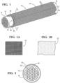
- Figure 1 shows a tubular textile sleeve, referred to hereafter as sleeve 10, constructed according to one embodiment of the invention for providing protection against external radiant heat to elongate members, such as a hose, wires, or a wire harness 11, by way of example and without limitation, contained within the sleeve 10.
- the sleeve 10 has an inner wall 12, illustrated in Figure 1 as a seamless and circumferential ly continuous wall, with a reflective outer layer 14 bonded to an outer surface of the inner wall 12.
- the inner wall 12 has an inner surface that defines a central cavity 16 sized for receipt of the elongate members 11 therein, wherein the cavity 16 extends axially along a central longitudinal axis 18 between opposite ends 20, 22 of the sleeve 10.
- the reflective outer layer 14 provides a thermal barrier to the inner wall 12 and the elongate members 11 against external radiant heat, thereby protecting the elongate members 11 against unwanted exposed to external radiant heat.
- the reflective outer layer 14 is provided as an outermost layer, preferably as a layer of foil, such as aluminum, by way of example and without limitation, having micro-perforated holes 24.
- the micro-perforated holes 24 enhance the ability of the sleeve 10 to be flexed and routed over meandering paths without tearing or cracking the foil outer layer 14. Further, with the micro-perforated holes 24 being micro-sized, it has been found via experimentation that the holes 24, as formed in accordance with the invention, do not sacrifice or otherwise lessen the ability of the outer foil layer 14 to perform its intended function of reflecting external radiant heat, thereby providing insulative protection to the elongate members 11 contained within the cavity 16 of the sleeve 10. Further, by minimizing the propensity of crack or tear formation in the thin foil outer layer 14, the foil outer layer 14 provides the sleeve 10 with enhanced durability and life expectancy relative to imperforate foil layered sleeves.
- the inner wall 12 can be constructed having any suitable length and diameter, depending on the application and size of the elongate member 11 to be protected.
- the inner wall 12 can be constructed from any suitable interlaced yarn filaments ( Figure 1A ), including monofilaments and/or multifilaments, via weaving, knitting, braiding, having a desired interlace pattern for the intended application, or from a layer of nonwoven material 12' ( Figure 1B ). Accordingly, the inner wall 12 can be constructed having various structural properties and configurations.
- the foil outer layer 14 is provided as a standard thickness wrappable foil, and has micro-sized perforate holes 24 ranging between about 50-300 ⁇ m in diameter, and more preferably ranging between about 50-100 ⁇ m in diameter, and in one example, were formed being 50 ⁇ m in diameter.
- the holes 24 are formed over the entirety or substantial entirely of the foil outer layer 14 having a generally uniform density between about 300-340 holes per square inch (46.5-52.7 holes per square cm), and in one example, were formed having a generally uniform density of about 320 holes per square inch (49.6 holes per square cm).
- the size and density of the holes 24 have been found to provide the sleeve 10 with enhance flexibility without causing the foil outer layer 14 to tear or crack in use, such as while being bent or routed over meandering paths, while also retaining the emissivity of the foil outer layer 14 as compared to an imperforate sheet of the foil, thereby being fully functional to protect inner wall 12 and the elongate members 11 within the cavity 16 of the sleeve 10 from exposure to external radiant heat.
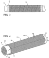
- the foil outer layer 14 can be provided in rectangular sheets sized to be "cigarette" wrapped about the inner wall 12 to bring opposite edges 23, 25 of the foil outer layer 14 into overlapping, bonded relation with one another, as best shown in Figure 2 , or it can be provided in a suitable width elongate strip and then spiral wrapped about the wall 12, as desired ( Figure 3 ). Any suitable adhesive can be used to facilitate bonding the foil outer layer 14 to an outer surface of the inner wall 12.
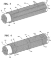
- a sleeve 110 constructed in accordance with another aspect of the invention is shown, wherein the same reference numerals, offset by a factor of 100, are used to identify like features.
- the sleeve 110 has an inner wall 112 constructed as a wrappable wall, and can be formed as a self-wrapping, "cigarette" type wall, if desired.
- the inner wall 112 has opposite edges 26, 28 extending generally parallel to a central longitudinal axis 118 between opposite ends 120, 122 of the sleeve 110, wherein the opposite edges 26, 28 are brought into overlapping relation with one another to circumferentially bound a central cavity 116.
- the wall 112 Upon forming the inner wall 112, such as from interlaced yarn filaments ( Figure 1A ) or a nonwoven material ( Figure 1B ), as discussed above, the wall 112 can be laminated with a foil outer layer 114, wherein the foil outer layer 114 is formed from the same metal foil materials and with the same size and density of micro-sized holes 124 as discussed above, preferably over the entirety of the foil outer layer 114.
- the laminated wall can be wrapped into its tubular form to bring the opposite edges 26, 28 into overlapping relation with one another.
- the inner wall 112 can be heat-set to take on a self-wrapping configuration, such that the opposite edges 26, 28 are automatically biased into overlapping relation with one another in the absence of an externally applied force.
- the inner wall 114 is formed from interlaced yarn, at least some of the circumferentially extending yarn filaments can be provided as heat-settable yarn filaments to facilitate heat-setting the inner wall 114 into a tubular configuration. With the foil outer layer 114 fully covering an outer surface of the inner wall 112, the entire circumference of the sleeve 110 is assured of being covered by the foil outer layer 114.
- the opposite edges 26, 28 can remain free to be biased by an externally applied force to open the sleeve 110 along its length to facilitate placing the sleeve about the elongate member 111 or to remove the sleeve 110 from the elongate member 111, such as during service.
- a perforated strip of foil tape 30, having the same size, pattern and density of holes 124, as discussed above, can be applied along at least a portion of, or along the entirety of the seam formed by the overlapping edges 26, 28 to completely seal the seam between the overlapping edges 26, 28.
- the perforated foil tape 30 can be applied as a single strip over the entirety overlapping edges 26, 28 in generally parallel relation to the axis 118 to prevent the opposite edges 26, 28 from being inadvertently opened and to prevent the ingress of contamination.
- individual strips of the perforated foil tape 30 could be wrapped circumferentially about the sleeve 110, if desired, thereby preventing the opposite edges 26, 28 from being inadvertently opened.
- sleeves 10, 110 constructed in accordance with the invention are suitable for use in a variety of applications, regardless of the sizes and lengths required. For example, they could be used in automotive, marine, industrial, aeronautical or aerospace applications, or any other application wherein protective sleeves are desired to protect nearby components against heat radiation.
Landscapes
- Engineering & Computer Science (AREA)
- Textile Engineering (AREA)
- Mechanical Engineering (AREA)
- General Engineering & Computer Science (AREA)
- Physics & Mathematics (AREA)
- Electromagnetism (AREA)
- Thermal Insulation (AREA)
- Woven Fabrics (AREA)
- Details Of Indoor Wiring (AREA)
- Ropes Or Cables (AREA)
- Laminated Bodies (AREA)
- Tents Or Canopies (AREA)
Claims (15)
- Schutzhülse (10; 110) zum Bereitstellen eines Schutzes für längliche Elemente (11), die innerhalb der Hülse enthalten sind, gegen äußere Strahlungswärme, umfassend:eine innere Textilwand (12; 12'; 112), die eine äußere Oberfläche und eine innere Oberfläche aufweist, wobei die innere Oberfläche konfiguriert ist, um einen Hohlraum (16; 116) für einen Empfang der länglichen Elemente abzugrenzen; undeine äußere Folienschicht (14; 114), die an die äußere Oberfläche der inneren Textilwand (12; 12'; 112) geklebt ist,dadurch gekennzeichnet, dass die äußere Folienschicht mikroperforierte Löcher (24; 124) aufweist,wobei die mikroperforierten Löcher (24; 124) einen Durchmesser zwischen etwa 50-300 µm aufweisen und eine Dichte zwischen etwa 300-340 Löcher pro Quadratzoll (46,5-52,7 Löcher pro Quadratzentimeter) aufweisen.
- Schutzhülse (10; 110) nach Anspruch 1, wobei die mikroperforierten Löcher (24; 124) eine im Allgemeinen gleichmäßige Dichte über die wesentliche Gesamtheit der Folienschicht (14; 114) aufweisen.
- Schutzhülse (10; 110) nach Anspruch 2, wobei die mikroperforierten Löcher (24; 124) einen Durchmesser zwischen etwa 50-100 µm aufweisen.
- Schutzhülse (10; 110) nach Anspruch 1, wobei die mikroperforierten Löcher (24; 124) einen Durchmesser zwischen etwa 50-100 µm aufweisen.
- Schutzhülse (110) nach Anspruch 1, wobei die innere Textilwand (112) gegenüberliegende Kanten (26, 28), die sich entlang einer Längsachse (118) der Hülse zwischen gegenüberliegende Enden (120, 122) erstrecken, aufweist, wobei die gegenüberliegenden Kanten in überlappender Beziehung miteinander um die Längsachse herum gewickelt werden.
- Schutzhülse (110) nach Anspruch 5, wobei die innere Textilwand (112) wärmefixiert ist, um die gegenüberliegenden Kanten (26, 28) in überlappender Beziehung miteinander vorzuspannen oderwobei die innere Textilwand aus verflochtenen Fadenfilamenten ausgebildet ist oderwobei die innere Textilwand aus einem Vliesmaterial ausgebildet ist oderwobei die überlappenden gegenüberliegenden Kanten eine Naht entlang der Länge der inneren Textilwand ausbilden und ferner einschließend ein Folienband (30), das über zumindest einen Abschnitt der Naht geklebt ist, wobei das Folienband mikroperforierte Löcher (124) aufweist, wobei sich optional das Folienband über die wesentliche Gesamtheit der Naht erstreckt.
- Schutzhülse (10) nach Anspruch 1, wobei die innere Textilwand (12; 12') in Umfangsrichtung fortlaufend ist.
- Schutzhülse (10) nach Anspruch 7, wobei die äußere Folienschicht (14) gegenüberliegende Kanten (23, 25), die einander überlappen, aufweist oder
wobei die äußere Folienschicht um die innere Textilwand (12) herum spiralförmig gewickelt ist. - Verfahren zum Konstruieren einer rohrförmigen Hülse (10; 110) zum Bereitstellen des Schutzes für längliche Elemente (11), die innerhalb der Hülse enthalten sind, gegen äußere Strahlungswärme, umfassend:Ausbilden einer inneren Textilwand (12; 12'; 112), die eine äußere Oberfläche und eine innere Oberfläche, die konfiguriert sind, um einen Hohlraum (16; 116) für den Empfang der länglichen Elemente abzugrenzen, aufweist; undKleben einer äußeren Folienschicht (14; 114) an die äußere Oberfläche der inneren Textilwand (12; 12'; 112),dadurch gekennzeichnet, dass die äußere Folienschicht mikroperforierte Löcher (24; 124) aufweist,und ferner gekennzeichnet durch Ausbilden der mikroperforierten Löcher (24; 124), die einen Durchmesser zwischen etwa 50-300 µm aufweisen; und durch Perforieren der mikrogroßen Löcher, die eine Dichte zwischen etwa 300-340 Löcher pro Quadratzoll (46,5-52,7 Löcher pro Quadratzentimeter) aufweisen.
- Verfahren nach Anspruch 9, ferner einschließend das Ausbilden der mikroperforierten Löcher (24; 124), die eine im Allgemeinen gleichmäßige Dichte über die wesentliche Gesamtheit der Folienschicht aufweisen.
- Verfahren nach Anspruch 10, ferner einschließend das Ausbilden der mikroperforierten Löcher (24; 124), die einen Durchmesser zwischen etwa 50-100 µm aufweisen.
- Verfahren nach Anspruch 9, ferner einschließend das Ausbilden der mikroperforierten Löcher (24; 124), die einen Durchmesser zwischen etwa 50-100 µm aufweisen.
- Verfahren nach Anspruch 9, ferner einschließend das Ausbilden der inneren Textilwand (112), die gegenüberliegende Kanten (26, 28), die sich entlang einer Längsachse (118) der Hülse (110) zwischen gegenüberliegenden Enden (120, 122) erstrecken, aufweist und Wickeln der gegenüberliegenden Kanten um die Längsachse herum in überlappender Beziehung miteinander.
- Verfahren nach Anspruch 13, ferner einschließend ein Wärmefixieren der inneren Textilwand (112), um die gegenüberliegenden Kanten (26, 28) in überlappender Beziehung miteinander vorzuspannen oderferner einschließend das Ausbilden des inneren Textils mit verflochtenen Fadenfilamenten oderferner einschließend das Ausbilden der inneren Textilwand mit Vliesmaterial oderferner einschließend das Kleben eines Folienbands (30) mit mikroperforierten Löchern (124) über zumindest einen Abschnitt einer Naht, die zwischen den gegenüberliegenden Kanten ausgebildet ist, wobei optional ferner einschließend das Kleben des Folienbands über die wesentliche Gesamtheit der Naht.
- Verfahren nach Anspruch 9, ferner einschließend das Ausbilden der inneren Textilwand (12; 12'), die in Umfangsrichtung fortlaufend ist, wobei optional.ferner einschließend das Kleben gegenüberliegender Kanten (23, 25) der äußeren Folienschicht (14) in überlappender Beziehung miteinander oderferner einschließend das spiralförmige Wickeln der äußeren Folienschicht um die innere Textilwand herum.
Applications Claiming Priority (2)
| Application Number | Priority Date | Filing Date | Title |
|---|---|---|---|
| US201461987299P | 2014-05-01 | 2014-05-01 | |
| PCT/US2015/028768 WO2015168535A1 (en) | 2014-05-01 | 2015-05-01 | Micro-perforated reflective textile sleeve and method of construction thereof |
Publications (2)
| Publication Number | Publication Date |
|---|---|
| EP3137663A1 EP3137663A1 (de) | 2017-03-08 |
| EP3137663B1 true EP3137663B1 (de) | 2023-04-19 |
Family
ID=53783303
Family Applications (1)
| Application Number | Title | Priority Date | Filing Date |
|---|---|---|---|
| EP15722395.9A Active EP3137663B1 (de) | 2014-05-01 | 2015-05-01 | Mikroperforierte rückstrahlende textilhülle und konstruktionsverfahren dafür |
Country Status (7)
| Country | Link |
|---|---|
| US (1) | US20150314551A1 (de) |
| EP (1) | EP3137663B1 (de) |
| JP (1) | JP6641293B2 (de) |
| KR (1) | KR20160146771A (de) |
| CN (1) | CN106414054B (de) |
| BR (1) | BR112016025320A2 (de) |
| WO (1) | WO2015168535A1 (de) |
Families Citing this family (6)
| Publication number | Priority date | Publication date | Assignee | Title |
|---|---|---|---|---|
| DE102016110608A1 (de) * | 2016-06-08 | 2017-12-14 | Michael Lindner | Schutzvorrichtung für eine Leitung |
| US10982355B2 (en) * | 2016-07-25 | 2021-04-20 | Federal-Mogul Powertrain Llc | Knit tubular protective sleeve and method of construction thereof |
| US20190308385A1 (en) * | 2018-04-06 | 2019-10-10 | Federal-Mogul Powertrain Llc | Self-wrapping sleeve and method of construction thereof |
| US11401631B2 (en) * | 2019-10-28 | 2022-08-02 | Federal-Mogul Powertrain Llc | Impact resistant, wrappable multilayered woven sleeve and method of construction thereof |
| CN111267753A (zh) * | 2020-03-03 | 2020-06-12 | 一汽解放汽车有限公司 | 一种管线束支架 |
| WO2022187257A1 (en) * | 2021-03-02 | 2022-09-09 | TemperPack Technologies, Inc. | Recyclable insulation material, methods for making, and machines for making |
Citations (1)
| Publication number | Priority date | Publication date | Assignee | Title |
|---|---|---|---|---|
| GB2249753A (en) * | 1990-11-13 | 1992-05-20 | T & N Technology Ltd | A flexible sheet material |
Family Cites Families (22)
| Publication number | Priority date | Publication date | Assignee | Title |
|---|---|---|---|---|
| JPS5137211Y2 (de) * | 1972-02-29 | 1976-09-11 | ||
| DE7930401U1 (de) * | 1979-09-11 | 1980-03-13 | N.V. Raychem S.A., Kessel-Lo (Belgien) | Kabelmuffeneinlage |
| US4888234A (en) * | 1986-07-17 | 1989-12-19 | Gates Formed-Fibre Products, Inc. | Formable fiber composite |
| US5413149A (en) * | 1991-11-05 | 1995-05-09 | The Bentley-Harris Manufacturing Company | Shaped fabric products and methods of making same |
| US20020098311A1 (en) * | 1999-09-02 | 2002-07-25 | Michael Lindner | Protective sheathing |
| JP3791676B2 (ja) * | 2001-11-19 | 2006-06-28 | 芦森工業株式会社 | 吸引筒状フィルター装置及びその筒状支持体 |
| FR2832487B1 (fr) * | 2001-11-21 | 2004-02-13 | Fed Mogul Systems Prot Group | Gaine de protection pour tube de circulation de fluide |
| DE10253830A1 (de) * | 2002-11-18 | 2004-06-03 | Carcoustics Tech Center Gmbh | Perforierte Folie und Verfahren sowie Vorrichtung zum Perforieren eines flächigen Materials |
| SE525985C2 (sv) * | 2003-10-17 | 2005-06-07 | Saint Gobain Isover Ab | Isoleringssystem till tekniska installationer |
| US7410550B2 (en) * | 2003-12-11 | 2008-08-12 | Sherwin Michael J | Flexible insulating sleeve |
| JP2007335565A (ja) * | 2006-06-14 | 2007-12-27 | Inoac Corp | 電磁シールドスリーブ |
| JP2007335566A (ja) * | 2006-06-14 | 2007-12-27 | Inoac Corp | 電磁シールドスリーブの製造方法 |
| JP2008137360A (ja) * | 2006-12-05 | 2008-06-19 | Tokai Rubber Ind Ltd | 冷媒輸送用ホースおよびその製法 |
| US20090311456A1 (en) * | 2008-06-12 | 2009-12-17 | Harris David A | Non-woven, self-wrapping thermal sleeve |
| CA2751352C (en) * | 2008-09-11 | 2017-01-31 | Albany International Corp. | Permeable belt for the manufacture of tissue towel and nonwovens |
| BRPI0918561B1 (pt) * | 2008-09-11 | 2019-06-18 | Albany International Corp. | Membros de suporte de não tecido contínuo |
| WO2011143193A2 (en) * | 2010-05-10 | 2011-11-17 | Federal-Mogul Powertrain, Inc. | Non-woven, self-wrapping thermal sleeve and method of construction thereof |
| JP6055474B2 (ja) * | 2011-08-22 | 2016-12-27 | フェデラル−モーグル・パワートレイン・リミテッド・ライアビリティ・カンパニーFederal−Mogul Powertrain Llc | 径方向に折畳および展開可能な繊維スリーブとその作製方法 |
| US9297491B2 (en) * | 2012-02-08 | 2016-03-29 | Federal-Mogul Powertrain, Inc. | Thermally resistant convoluted sleeve and method of construction thereof |
| US9976687B2 (en) * | 2012-05-18 | 2018-05-22 | Saprex, Llc | Breathable multi-component exhaust insulation system |
| WO2015031361A1 (en) * | 2013-08-26 | 2015-03-05 | Federal-Mogul Powertrain, Inc. | Wrappable multi-layer heat shield |
| US20150093556A1 (en) * | 2013-10-01 | 2015-04-02 | Federal-Mogul Powertrain, Inc. | Wrappable laminated textile sleeve with enhanced flexibility and method of reducing cracking in a foil layer of a wrappable textile sleeve |
-
2015
- 2015-05-01 CN CN201580025858.6A patent/CN106414054B/zh active Active
- 2015-05-01 US US14/701,875 patent/US20150314551A1/en not_active Abandoned
- 2015-05-01 JP JP2016565427A patent/JP6641293B2/ja active Active
- 2015-05-01 EP EP15722395.9A patent/EP3137663B1/de active Active
- 2015-05-01 WO PCT/US2015/028768 patent/WO2015168535A1/en not_active Ceased
- 2015-05-01 KR KR1020167030557A patent/KR20160146771A/ko not_active Withdrawn
- 2015-05-01 BR BR112016025320A patent/BR112016025320A2/pt not_active IP Right Cessation
Patent Citations (1)
| Publication number | Priority date | Publication date | Assignee | Title |
|---|---|---|---|---|
| GB2249753A (en) * | 1990-11-13 | 1992-05-20 | T & N Technology Ltd | A flexible sheet material |
Also Published As
| Publication number | Publication date |
|---|---|
| CN106414054B (zh) | 2018-10-12 |
| EP3137663A1 (de) | 2017-03-08 |
| KR20160146771A (ko) | 2016-12-21 |
| US20150314551A1 (en) | 2015-11-05 |
| BR112016025320A2 (pt) | 2017-08-15 |
| JP2017514727A (ja) | 2017-06-08 |
| WO2015168535A1 (en) | 2015-11-05 |
| JP6641293B2 (ja) | 2020-02-05 |
| CN106414054A (zh) | 2017-02-15 |
Similar Documents
| Publication | Publication Date | Title |
|---|---|---|
| EP3137663B1 (de) | Mikroperforierte rückstrahlende textilhülle und konstruktionsverfahren dafür | |
| JP4688107B2 (ja) | 例えば航空技術で用いるケーブル束を保護することを目的とする電磁遮蔽スリーブ | |
| CN101405529B (zh) | 抗端部磨损的织物、该织物形成的保护套管及其构造方法 | |
| EP3052312B1 (de) | Laminierte wickelbare textilhülse mit verbesserter flexibilität und verfahren zur reduzierung von rissbildung in einer folienschicht einer wickelbaren textilhülle | |
| EP2951340B1 (de) | Kräuselfreie selbstwickelnde gewebehülle und verfahren zur herstellung davon | |
| EP2812618B1 (de) | Wärmeisolierende und reflektierende gewundene hülse und verfahren zur konstruktion davon | |
| US10315379B2 (en) | Wrappable abrasion resistant, reflective thermal protective textile sleeve and method of construction thereof | |
| KR20130120471A (ko) | 배리어를 내장한 편성 배리어 확장부를 구비하는 편성 슬리브 및 그 제조 방법 | |
| US10211612B2 (en) | Protective textile sleeve with hot melt fixation, end fray prevention layer and methods of construction and application thereof | |
| US6897375B2 (en) | Protective device for elongated objects | |
| EP3005502B1 (de) | Ummantelte textilhülle mit verbundenem verschlussmechanismus und verfahren zur konstruktion davon | |
| US10578001B2 (en) | Thermally insulative, durable, reflective convoluted sleeve and method of construction thereof | |
| EP2719039B1 (de) | Reflektive textilhülle und verfahren zu ihrer herstellung | |
| US11421356B2 (en) | Braided, reflective textile sleeve and method of construction thereof | |
| EP4031418A1 (de) | Flexible wasserabweisende hochtemperaturbeständige umwickelbare hülse und verfahren zu deren herstellung |
Legal Events
| Date | Code | Title | Description |
|---|---|---|---|
| STAA | Information on the status of an ep patent application or granted ep patent |
Free format text: STATUS: THE INTERNATIONAL PUBLICATION HAS BEEN MADE |
|
| PUAI | Public reference made under article 153(3) epc to a published international application that has entered the european phase |
Free format text: ORIGINAL CODE: 0009012 |
|
| STAA | Information on the status of an ep patent application or granted ep patent |
Free format text: STATUS: REQUEST FOR EXAMINATION WAS MADE |
|
| 17P | Request for examination filed |
Effective date: 20161103 |
|
| AK | Designated contracting states |
Kind code of ref document: A1 Designated state(s): AL AT BE BG CH CY CZ DE DK EE ES FI FR GB GR HR HU IE IS IT LI LT LU LV MC MK MT NL NO PL PT RO RS SE SI SK SM TR |
|
| AX | Request for extension of the european patent |
Extension state: BA ME |
|
| RIN1 | Information on inventor provided before grant (corrected) |
Inventor name: CHEN, MING-MING Inventor name: HO, WAI, KIT |
|
| DAV | Request for validation of the european patent (deleted) | ||
| DAX | Request for extension of the european patent (deleted) | ||
| RAP1 | Party data changed (applicant data changed or rights of an application transferred) |
Owner name: FEDERAL-MOGUL POWERTRAIN LLC |
|
| STAA | Information on the status of an ep patent application or granted ep patent |
Free format text: STATUS: EXAMINATION IS IN PROGRESS |
|
| 17Q | First examination report despatched |
Effective date: 20210326 |
|
| REG | Reference to a national code |
Ref country code: DE Ref legal event code: R079 Free format text: PREVIOUS MAIN CLASS: D03D0001000000 Ipc: B32B0001080000 Ref country code: DE Ref legal event code: R079 Ref document number: 602015083217 Country of ref document: DE Free format text: PREVIOUS MAIN CLASS: D03D0001000000 Ipc: B32B0001080000 |
|
| RIC1 | Information provided on ipc code assigned before grant |
Ipc: D03D 15/567 20210101ALI20220818BHEP Ipc: D03D 15/00 20060101ALI20220818BHEP Ipc: D03D 3/02 20060101ALI20220818BHEP Ipc: D03D 1/00 20060101ALI20220818BHEP Ipc: B32B 38/04 20060101ALI20220818BHEP Ipc: B32B 5/28 20060101ALI20220818BHEP Ipc: B32B 5/24 20060101ALI20220818BHEP Ipc: B60R 16/02 20060101ALI20220818BHEP Ipc: B32B 15/14 20060101ALI20220818BHEP Ipc: B32B 5/02 20060101ALI20220818BHEP Ipc: B32B 1/08 20060101AFI20220818BHEP |
|
| GRAP | Despatch of communication of intention to grant a patent |
Free format text: ORIGINAL CODE: EPIDOSNIGR1 |
|
| STAA | Information on the status of an ep patent application or granted ep patent |
Free format text: STATUS: GRANT OF PATENT IS INTENDED |
|
| GRAJ | Information related to disapproval of communication of intention to grant by the applicant or resumption of examination proceedings by the epo deleted |
Free format text: ORIGINAL CODE: EPIDOSDIGR1 |
|
| STAA | Information on the status of an ep patent application or granted ep patent |
Free format text: STATUS: EXAMINATION IS IN PROGRESS |
|
| INTG | Intention to grant announced |
Effective date: 20221011 |
|
| GRAP | Despatch of communication of intention to grant a patent |
Free format text: ORIGINAL CODE: EPIDOSNIGR1 |
|
| STAA | Information on the status of an ep patent application or granted ep patent |
Free format text: STATUS: GRANT OF PATENT IS INTENDED |
|
| INTC | Intention to grant announced (deleted) | ||
| INTG | Intention to grant announced |
Effective date: 20221111 |
|
| GRAS | Grant fee paid |
Free format text: ORIGINAL CODE: EPIDOSNIGR3 |
|
| GRAA | (expected) grant |
Free format text: ORIGINAL CODE: 0009210 |
|
| STAA | Information on the status of an ep patent application or granted ep patent |
Free format text: STATUS: THE PATENT HAS BEEN GRANTED |
|
| AK | Designated contracting states |
Kind code of ref document: B1 Designated state(s): AL AT BE BG CH CY CZ DE DK EE ES FI FR GB GR HR HU IE IS IT LI LT LU LV MC MK MT NL NO PL PT RO RS SE SI SK SM TR |
|
| REG | Reference to a national code |
Ref country code: GB Ref legal event code: FG4D |
|
| REG | Reference to a national code |
Ref country code: DE Ref legal event code: R096 Ref document number: 602015083217 Country of ref document: DE |
|
| REG | Reference to a national code |
Ref country code: CH Ref legal event code: EP |
|
| REG | Reference to a national code |
Ref country code: IE Ref legal event code: FG4D |
|
| REG | Reference to a national code |
Ref country code: AT Ref legal event code: REF Ref document number: 1560891 Country of ref document: AT Kind code of ref document: T Effective date: 20230515 |
|
| REG | Reference to a national code |
Ref country code: LT Ref legal event code: MG9D |
|
| REG | Reference to a national code |
Ref country code: NL Ref legal event code: MP Effective date: 20230419 |
|
| REG | Reference to a national code |
Ref country code: AT Ref legal event code: MK05 Ref document number: 1560891 Country of ref document: AT Kind code of ref document: T Effective date: 20230419 |
|
| PG25 | Lapsed in a contracting state [announced via postgrant information from national office to epo] |
Ref country code: NL Free format text: LAPSE BECAUSE OF FAILURE TO SUBMIT A TRANSLATION OF THE DESCRIPTION OR TO PAY THE FEE WITHIN THE PRESCRIBED TIME-LIMIT Effective date: 20230419 |
|
| PG25 | Lapsed in a contracting state [announced via postgrant information from national office to epo] |
Ref country code: SE Free format text: LAPSE BECAUSE OF FAILURE TO SUBMIT A TRANSLATION OF THE DESCRIPTION OR TO PAY THE FEE WITHIN THE PRESCRIBED TIME-LIMIT Effective date: 20230419 Ref country code: PT Free format text: LAPSE BECAUSE OF FAILURE TO SUBMIT A TRANSLATION OF THE DESCRIPTION OR TO PAY THE FEE WITHIN THE PRESCRIBED TIME-LIMIT Effective date: 20230821 Ref country code: NO Free format text: LAPSE BECAUSE OF FAILURE TO SUBMIT A TRANSLATION OF THE DESCRIPTION OR TO PAY THE FEE WITHIN THE PRESCRIBED TIME-LIMIT Effective date: 20230719 Ref country code: ES Free format text: LAPSE BECAUSE OF FAILURE TO SUBMIT A TRANSLATION OF THE DESCRIPTION OR TO PAY THE FEE WITHIN THE PRESCRIBED TIME-LIMIT Effective date: 20230419 Ref country code: AT Free format text: LAPSE BECAUSE OF FAILURE TO SUBMIT A TRANSLATION OF THE DESCRIPTION OR TO PAY THE FEE WITHIN THE PRESCRIBED TIME-LIMIT Effective date: 20230419 |
|
| PG25 | Lapsed in a contracting state [announced via postgrant information from national office to epo] |
Ref country code: RS Free format text: LAPSE BECAUSE OF FAILURE TO SUBMIT A TRANSLATION OF THE DESCRIPTION OR TO PAY THE FEE WITHIN THE PRESCRIBED TIME-LIMIT Effective date: 20230419 Ref country code: PL Free format text: LAPSE BECAUSE OF FAILURE TO SUBMIT A TRANSLATION OF THE DESCRIPTION OR TO PAY THE FEE WITHIN THE PRESCRIBED TIME-LIMIT Effective date: 20230419 Ref country code: LV Free format text: LAPSE BECAUSE OF FAILURE TO SUBMIT A TRANSLATION OF THE DESCRIPTION OR TO PAY THE FEE WITHIN THE PRESCRIBED TIME-LIMIT Effective date: 20230419 Ref country code: LT Free format text: LAPSE BECAUSE OF FAILURE TO SUBMIT A TRANSLATION OF THE DESCRIPTION OR TO PAY THE FEE WITHIN THE PRESCRIBED TIME-LIMIT Effective date: 20230419 Ref country code: IS Free format text: LAPSE BECAUSE OF FAILURE TO SUBMIT A TRANSLATION OF THE DESCRIPTION OR TO PAY THE FEE WITHIN THE PRESCRIBED TIME-LIMIT Effective date: 20230819 Ref country code: HR Free format text: LAPSE BECAUSE OF FAILURE TO SUBMIT A TRANSLATION OF THE DESCRIPTION OR TO PAY THE FEE WITHIN THE PRESCRIBED TIME-LIMIT Effective date: 20230419 Ref country code: GR Free format text: LAPSE BECAUSE OF FAILURE TO SUBMIT A TRANSLATION OF THE DESCRIPTION OR TO PAY THE FEE WITHIN THE PRESCRIBED TIME-LIMIT Effective date: 20230720 Ref country code: AL Free format text: LAPSE BECAUSE OF FAILURE TO SUBMIT A TRANSLATION OF THE DESCRIPTION OR TO PAY THE FEE WITHIN THE PRESCRIBED TIME-LIMIT Effective date: 20230419 |
|
| PG25 | Lapsed in a contracting state [announced via postgrant information from national office to epo] |
Ref country code: FI Free format text: LAPSE BECAUSE OF FAILURE TO SUBMIT A TRANSLATION OF THE DESCRIPTION OR TO PAY THE FEE WITHIN THE PRESCRIBED TIME-LIMIT Effective date: 20230419 |
|
| REG | Reference to a national code |
Ref country code: CH Ref legal event code: PL |
|
| PG25 | Lapsed in a contracting state [announced via postgrant information from national office to epo] |
Ref country code: SK Free format text: LAPSE BECAUSE OF FAILURE TO SUBMIT A TRANSLATION OF THE DESCRIPTION OR TO PAY THE FEE WITHIN THE PRESCRIBED TIME-LIMIT Effective date: 20230419 |
|
| PG25 | Lapsed in a contracting state [announced via postgrant information from national office to epo] |
Ref country code: MC Free format text: LAPSE BECAUSE OF FAILURE TO SUBMIT A TRANSLATION OF THE DESCRIPTION OR TO PAY THE FEE WITHIN THE PRESCRIBED TIME-LIMIT Effective date: 20230419 |
|
| REG | Reference to a national code |
Ref country code: DE Ref legal event code: R097 Ref document number: 602015083217 Country of ref document: DE |
|
| REG | Reference to a national code |
Ref country code: BE Ref legal event code: MM Effective date: 20230531 |
|
| PG25 | Lapsed in a contracting state [announced via postgrant information from national office to epo] |
Ref country code: SM Free format text: LAPSE BECAUSE OF FAILURE TO SUBMIT A TRANSLATION OF THE DESCRIPTION OR TO PAY THE FEE WITHIN THE PRESCRIBED TIME-LIMIT Effective date: 20230419 Ref country code: SK Free format text: LAPSE BECAUSE OF FAILURE TO SUBMIT A TRANSLATION OF THE DESCRIPTION OR TO PAY THE FEE WITHIN THE PRESCRIBED TIME-LIMIT Effective date: 20230419 Ref country code: RO Free format text: LAPSE BECAUSE OF FAILURE TO SUBMIT A TRANSLATION OF THE DESCRIPTION OR TO PAY THE FEE WITHIN THE PRESCRIBED TIME-LIMIT Effective date: 20230419 Ref country code: MC Free format text: LAPSE BECAUSE OF FAILURE TO SUBMIT A TRANSLATION OF THE DESCRIPTION OR TO PAY THE FEE WITHIN THE PRESCRIBED TIME-LIMIT Effective date: 20230419 Ref country code: LU Free format text: LAPSE BECAUSE OF NON-PAYMENT OF DUE FEES Effective date: 20230501 Ref country code: LI Free format text: LAPSE BECAUSE OF NON-PAYMENT OF DUE FEES Effective date: 20230531 Ref country code: EE Free format text: LAPSE BECAUSE OF FAILURE TO SUBMIT A TRANSLATION OF THE DESCRIPTION OR TO PAY THE FEE WITHIN THE PRESCRIBED TIME-LIMIT Effective date: 20230419 Ref country code: DK Free format text: LAPSE BECAUSE OF FAILURE TO SUBMIT A TRANSLATION OF THE DESCRIPTION OR TO PAY THE FEE WITHIN THE PRESCRIBED TIME-LIMIT Effective date: 20230419 Ref country code: CZ Free format text: LAPSE BECAUSE OF FAILURE TO SUBMIT A TRANSLATION OF THE DESCRIPTION OR TO PAY THE FEE WITHIN THE PRESCRIBED TIME-LIMIT Effective date: 20230419 Ref country code: CH Free format text: LAPSE BECAUSE OF NON-PAYMENT OF DUE FEES Effective date: 20230531 |
|
| PLBE | No opposition filed within time limit |
Free format text: ORIGINAL CODE: 0009261 |
|
| STAA | Information on the status of an ep patent application or granted ep patent |
Free format text: STATUS: NO OPPOSITION FILED WITHIN TIME LIMIT |
|
| REG | Reference to a national code |
Ref country code: IE Ref legal event code: MM4A |
|
| 26N | No opposition filed |
Effective date: 20240122 |
|
| GBPC | Gb: european patent ceased through non-payment of renewal fee |
Effective date: 20230719 |
|
| PG25 | Lapsed in a contracting state [announced via postgrant information from national office to epo] |
Ref country code: IE Free format text: LAPSE BECAUSE OF NON-PAYMENT OF DUE FEES Effective date: 20230501 |
|
| PG25 | Lapsed in a contracting state [announced via postgrant information from national office to epo] |
Ref country code: IE Free format text: LAPSE BECAUSE OF NON-PAYMENT OF DUE FEES Effective date: 20230501 Ref country code: GB Free format text: LAPSE BECAUSE OF NON-PAYMENT OF DUE FEES Effective date: 20230719 |
|
| PG25 | Lapsed in a contracting state [announced via postgrant information from national office to epo] |
Ref country code: SI Free format text: LAPSE BECAUSE OF FAILURE TO SUBMIT A TRANSLATION OF THE DESCRIPTION OR TO PAY THE FEE WITHIN THE PRESCRIBED TIME-LIMIT Effective date: 20230419 |
|
| PG25 | Lapsed in a contracting state [announced via postgrant information from national office to epo] |
Ref country code: SI Free format text: LAPSE BECAUSE OF FAILURE TO SUBMIT A TRANSLATION OF THE DESCRIPTION OR TO PAY THE FEE WITHIN THE PRESCRIBED TIME-LIMIT Effective date: 20230419 Ref country code: IT Free format text: LAPSE BECAUSE OF FAILURE TO SUBMIT A TRANSLATION OF THE DESCRIPTION OR TO PAY THE FEE WITHIN THE PRESCRIBED TIME-LIMIT Effective date: 20230419 Ref country code: FR Free format text: LAPSE BECAUSE OF NON-PAYMENT OF DUE FEES Effective date: 20230619 Ref country code: BE Free format text: LAPSE BECAUSE OF NON-PAYMENT OF DUE FEES Effective date: 20230531 |
|
| PG25 | Lapsed in a contracting state [announced via postgrant information from national office to epo] |
Ref country code: BG Free format text: LAPSE BECAUSE OF FAILURE TO SUBMIT A TRANSLATION OF THE DESCRIPTION OR TO PAY THE FEE WITHIN THE PRESCRIBED TIME-LIMIT Effective date: 20230419 |
|
| PG25 | Lapsed in a contracting state [announced via postgrant information from national office to epo] |
Ref country code: BG Free format text: LAPSE BECAUSE OF FAILURE TO SUBMIT A TRANSLATION OF THE DESCRIPTION OR TO PAY THE FEE WITHIN THE PRESCRIBED TIME-LIMIT Effective date: 20230419 |
|
| PGFP | Annual fee paid to national office [announced via postgrant information from national office to epo] |
Ref country code: DE Payment date: 20250423 Year of fee payment: 11 |
|
| PG25 | Lapsed in a contracting state [announced via postgrant information from national office to epo] |
Ref country code: CY Free format text: LAPSE BECAUSE OF FAILURE TO SUBMIT A TRANSLATION OF THE DESCRIPTION OR TO PAY THE FEE WITHIN THE PRESCRIBED TIME-LIMIT; INVALID AB INITIO Effective date: 20150501 |
|
| PG25 | Lapsed in a contracting state [announced via postgrant information from national office to epo] |
Ref country code: HU Free format text: LAPSE BECAUSE OF FAILURE TO SUBMIT A TRANSLATION OF THE DESCRIPTION OR TO PAY THE FEE WITHIN THE PRESCRIBED TIME-LIMIT; INVALID AB INITIO Effective date: 20150501 |
|
| REG | Reference to a national code |
Ref country code: DE Ref legal event code: R081 Ref document number: 602015083217 Country of ref document: DE Owner name: SYSTEMS PROTECTION GROUP US LLC (N.D.GES.D. ST, US Free format text: FORMER OWNER: FEDERAL-MOGUL POWERTRAIN LLC, SOUTHFIELD, MI, US |
|
| PG25 | Lapsed in a contracting state [announced via postgrant information from national office to epo] |
Ref country code: TR Free format text: LAPSE BECAUSE OF FAILURE TO SUBMIT A TRANSLATION OF THE DESCRIPTION OR TO PAY THE FEE WITHIN THE PRESCRIBED TIME-LIMIT Effective date: 20230419 |