EP3137239B1 - Verfahren und vorrichtung zur herstellung eines rohrförmigen schalungselements aus metallblech - Google Patents
Verfahren und vorrichtung zur herstellung eines rohrförmigen schalungselements aus metallblech Download PDFInfo
- Publication number
- EP3137239B1 EP3137239B1 EP15724181.1A EP15724181A EP3137239B1 EP 3137239 B1 EP3137239 B1 EP 3137239B1 EP 15724181 A EP15724181 A EP 15724181A EP 3137239 B1 EP3137239 B1 EP 3137239B1
- Authority
- EP
- European Patent Office
- Prior art keywords
- blank
- forming
- roll
- relief
- rolls
- Prior art date
- Legal status (The legal status is an assumption and is not a legal conclusion. Google has not performed a legal analysis and makes no representation as to the accuracy of the status listed.)
- Active
Links
Images


Classifications
-
- B—PERFORMING OPERATIONS; TRANSPORTING
- B21—MECHANICAL METAL-WORKING WITHOUT ESSENTIALLY REMOVING MATERIAL; PUNCHING METAL
- B21C—MANUFACTURE OF METAL SHEETS, WIRE, RODS, TUBES, PROFILES OR LIKE SEMI-MANUFACTURED PRODUCTS OTHERWISE THAN BY ROLLING; AUXILIARY OPERATIONS USED IN CONNECTION WITH METAL-WORKING WITHOUT ESSENTIALLY REMOVING MATERIAL
- B21C37/00—Manufacture of metal sheets, rods, wire, tubes, profiles or like semi-manufactured products, not otherwise provided for; Manufacture of tubes of special shape
- B21C37/06—Manufacture of metal sheets, rods, wire, tubes, profiles or like semi-manufactured products, not otherwise provided for; Manufacture of tubes of special shape of tubes or metal hoses; Combined procedures for making tubes, e.g. for making multi-wall tubes
- B21C37/08—Making tubes with welded or soldered seams
- B21C37/0815—Making tubes with welded or soldered seams without continuous longitudinal movement of the sheet during the bending operation
-
- B—PERFORMING OPERATIONS; TRANSPORTING
- B21—MECHANICAL METAL-WORKING WITHOUT ESSENTIALLY REMOVING MATERIAL; PUNCHING METAL
- B21C—MANUFACTURE OF METAL SHEETS, WIRE, RODS, TUBES, PROFILES OR LIKE SEMI-MANUFACTURED PRODUCTS OTHERWISE THAN BY ROLLING; AUXILIARY OPERATIONS USED IN CONNECTION WITH METAL-WORKING WITHOUT ESSENTIALLY REMOVING MATERIAL
- B21C37/00—Manufacture of metal sheets, rods, wire, tubes, profiles or like semi-manufactured products, not otherwise provided for; Manufacture of tubes of special shape
- B21C37/06—Manufacture of metal sheets, rods, wire, tubes, profiles or like semi-manufactured products, not otherwise provided for; Manufacture of tubes of special shape of tubes or metal hoses; Combined procedures for making tubes, e.g. for making multi-wall tubes
- B21C37/08—Making tubes with welded or soldered seams
- B21C37/083—Supply, or operations combined with supply, of strip material
-
- B—PERFORMING OPERATIONS; TRANSPORTING
- B21—MECHANICAL METAL-WORKING WITHOUT ESSENTIALLY REMOVING MATERIAL; PUNCHING METAL
- B21D—WORKING OR PROCESSING OF SHEET METAL OR METAL TUBES, RODS OR PROFILES WITHOUT ESSENTIALLY REMOVING MATERIAL; PUNCHING METAL
- B21D17/00—Forming single grooves in sheet metal or tubular or hollow articles
- B21D17/04—Forming single grooves in sheet metal or tubular or hollow articles by rolling
-
- B—PERFORMING OPERATIONS; TRANSPORTING
- B21—MECHANICAL METAL-WORKING WITHOUT ESSENTIALLY REMOVING MATERIAL; PUNCHING METAL
- B21D—WORKING OR PROCESSING OF SHEET METAL OR METAL TUBES, RODS OR PROFILES WITHOUT ESSENTIALLY REMOVING MATERIAL; PUNCHING METAL
- B21D5/00—Bending sheet metal along straight lines, e.g. to form simple curves
- B21D5/06—Bending sheet metal along straight lines, e.g. to form simple curves by drawing procedure making use of dies or forming-rollers, e.g. making profiles
- B21D5/10—Bending sheet metal along straight lines, e.g. to form simple curves by drawing procedure making use of dies or forming-rollers, e.g. making profiles for making tubes
- B21D5/12—Bending sheet metal along straight lines, e.g. to form simple curves by drawing procedure making use of dies or forming-rollers, e.g. making profiles for making tubes making use of forming-rollers
-
- B—PERFORMING OPERATIONS; TRANSPORTING
- B21—MECHANICAL METAL-WORKING WITHOUT ESSENTIALLY REMOVING MATERIAL; PUNCHING METAL
- B21D—WORKING OR PROCESSING OF SHEET METAL OR METAL TUBES, RODS OR PROFILES WITHOUT ESSENTIALLY REMOVING MATERIAL; PUNCHING METAL
- B21D5/00—Bending sheet metal along straight lines, e.g. to form simple curves
- B21D5/14—Bending sheet metal along straight lines, e.g. to form simple curves by passing between rollers
-
- B—PERFORMING OPERATIONS; TRANSPORTING
- B21—MECHANICAL METAL-WORKING WITHOUT ESSENTIALLY REMOVING MATERIAL; PUNCHING METAL
- B21D—WORKING OR PROCESSING OF SHEET METAL OR METAL TUBES, RODS OR PROFILES WITHOUT ESSENTIALLY REMOVING MATERIAL; PUNCHING METAL
- B21D53/00—Making other particular articles
- B21D53/02—Making other particular articles heat exchangers or parts thereof, e.g. radiators, condensers fins, headers
- B21D53/06—Making other particular articles heat exchangers or parts thereof, e.g. radiators, condensers fins, headers of metal tubes
-
- F—MECHANICAL ENGINEERING; LIGHTING; HEATING; WEAPONS; BLASTING
- F16—ENGINEERING ELEMENTS AND UNITS; GENERAL MEASURES FOR PRODUCING AND MAINTAINING EFFECTIVE FUNCTIONING OF MACHINES OR INSTALLATIONS; THERMAL INSULATION IN GENERAL
- F16L—PIPES; JOINTS OR FITTINGS FOR PIPES; SUPPORTS FOR PIPES, CABLES OR PROTECTIVE TUBING; MEANS FOR THERMAL INSULATION IN GENERAL
- F16L37/00—Couplings of the quick-acting type
- F16L37/02—Couplings of the quick-acting type in which the connection is maintained only by friction of the parts being joined
-
- F—MECHANICAL ENGINEERING; LIGHTING; HEATING; WEAPONS; BLASTING
- F16—ENGINEERING ELEMENTS AND UNITS; GENERAL MEASURES FOR PRODUCING AND MAINTAINING EFFECTIVE FUNCTIONING OF MACHINES OR INSTALLATIONS; THERMAL INSULATION IN GENERAL
- F16L—PIPES; JOINTS OR FITTINGS FOR PIPES; SUPPORTS FOR PIPES, CABLES OR PROTECTIVE TUBING; MEANS FOR THERMAL INSULATION IN GENERAL
- F16L9/00—Rigid pipes
- F16L9/17—Rigid pipes obtained by bending a sheet longitudinally and connecting the edges
Definitions
- the present invention relates to a method and a device for manufacturing tubular insulating elements sheet metal, according to the preambles of claims 1 and 7 respectively, which will be referred to later also by the names of pipes or ferrule.
- Such elements typically of cylindrical shape, and lengths of the order of 1000 or 1250 mm, also commonly referred to as "cross-section" are used for the heat insulation of heat transfer fluid pipes. They consist of a rectangular punched sheet blank, which is then bent, remaining open on a generatrix, so as to be inserted laterally around the conduit to heat insulation. The two opposite longitudinal edges are then connected to one another, by means of assembly screws for example. Furthermore, the axial ends of these insulating elements are shaped so that the elements can be assembled to each other by interlocking. The general principle of straight-line assembly retained is the interlocking with a male and female molding, this interlocking ensuring a good watertightness and sufficient rigidity, whether for a vertical or horizontal installation .
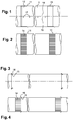
- each pipe 1 consisting of a rolled sheet blank closed by the connection of the longitudinal edges 18, 19.
- figure 1 illustrates an interlocking with a peripheral molding 11 formed in relief towards an end 12 of a smaller diameter of the pipe 1, the molding forming a stop when said end of a smaller diameter is fitted into the opposite cylindrical end 13 of a other pipe.
- the figure 2 illustrates a similar interlocking system but with a necking 14 in place of the "conicity" of the previous example, this shrinkage being obtained by the formation of axial corrugations distributed around the perimeter of the pipe.
- the figure 3 illustrates an edge-to-edge interlock, one end having a recessed molding 15 formed just at the edge of the pipe, into which the edge is inserted a relief molding 16 formed on the other end.
- the figure 4 illustrates an overlapping type interlocking, with one end with a narrowing 14 and undulations and a recessed molding 15 at the limit of the necking, the other end of the pipe fitting on said necking and further comprising a molding 16 embossed whose edge is inserted into said recessed molding.
- the moldings or corrugations formed towards the axial ends of the elements create a deformation of the entire thickness of the sheet, which must also remain smooth and without deformation between these deformed end zones.
- the material of the sheets used to make these pipes depends largely on the application. They may especially be aluminum, pre-painted steel, stainless steel or galvanized steel, the thickness of the sheet may generally vary from 0.4 to 1mm.
- the shaping operation of the ends is very important and must be carried out with great care by a person skilled in the art, the depth of the moldings and the repeatability of the result being important to guarantee a subsequent assembly and a homogeneous assembly of the heat-insulating elements. between them.
- a further disadvantage is that the surface of the shell or pipe may be damaged during the various manipulations required and in particular during several successive passes in the roller. In the case of coated steel blanks, these deteriorations pose an aesthetic problem but also a risk of corrosion later.
- the present invention aims to overcome the above problems and aims in particular to provide a method and a machine that automate the operations of rolling and molding in a single operation, and with great consistency in the result, and therefore a improvement of the quality of manufactured parts. It also aims to reduce handling and the time required for the manufacture of insulating elements as for the machine settings. It still aims to eliminate the effect of over-rolling and under running.
- the subject of the invention is a method of manufacturing a tubular thermal insulation element made of sheet metal with the steps of claim 1, said element consisting of a curved sheet blank including two longitudinal edges. opposing members are connected to each other along a longitudinal connecting line, said element having a peripheral relief formed on the sheet only in proximity to at least one axial end of the element, constituted by an edge of the blank orthogonal to the longitudinal edges, on the periphery of the element, said relief affecting the sheet over its entire thickness.
- this method is characterized in that said relief is formed on the edge of the blank (edge which will subsequently constitute an axial end of the heat-insulating element), the sheet blank being maintained at flat and driven in scrolling between two forming rollers in a direction parallel to said edge, and then the blank comprising said relief is bent by a bending roller cooperating with one of the forming rollers to bend the blank at its exit from the air gap between the forming rollers, immediately following the shaping of the relief during the scrolling of the blank, in a single pass.
- the shaping of the ends of the heat-insulating elements is carried out after this element has been given its cylindrical shape by rolling and pre-assembling its longitudinal edges, which causes the problems mentioned above.
- the desired shaping is carried out first of all on the edges of the blank held flat, and the rolling or bending is then carried out, then with the parade immediately following the shaping of the relief during the scrolling of the blank. , in one pass (one pass).
- Embossing is effected by passing the blank between two forming rollers, and bending is performed by a bending roll cooperating with one of the forming rollers to bend the blank immediately upon leaving the air gap between the forming rolls. .
- This arrangement allows on the one hand to use only one additional roll for the bending operation.
- the shaping is carried out simultaneously on both sides of the blank by the forms adapted for this purpose of the ends of the rollers, it also allows bending while the moldings formed by the forming rollers are still in contact with the forming roll, guided and supported by the forming roll on which the blank partially wraps under the effect of bending.
- the peripheral relief is formed in at least two shaping steps, comprising a roughing step and a finishing step, carried out successively during the scrolling of the sheet, each step being performed by a set of two rolls of shaping.
- This arrangement makes it possible to produce the reliefs in at least two stages, causing at each step smaller deformations on the edges of the blank, and thus generating fewer residual stresses in the material of the blank.
- This reduction in residual stresses is favorable to avoid overall deformations of the formed pipe and results in a more even profile and the elimination of over-rolling, with finally obtaining a pipe with identical diameters on the moldings.
- male and female made respectively at opposite ends of the pipe.
- the bending is carried out almost simultaneously to the shaping of the edges, which avoids or at least reduces the risk of deformation of the pipe, such as over-rolling and under-rolling defects pre-mentioned.
- a notable advantage of the method is that it is perfectly suited for applications even at large thicknesses and rigidities.
- the method according to the invention makes it possible to carry out the shaping operations used previously, in which the peripheral relief comprises a peripheral hollow or raised molding or a necking or a corrugation.
- the set of forming rollers comprises, successively in the direction of travel, a set of rough rolls and a set of finishing rolls.
- the mechanical force exerted for the operation of rolling and especially molding must be sufficient to achieve the desired deformation, it is advantageous to use at least two sets of shaping rollers acting successively, which reduce the efforts necessary for the plastic deformation of the blank, and therefore the power and rigidity of the machine, without affecting the quality of the moldings and the finished pipe.
- the machine can for example operate at a voltage of 220 volts mono and be mounted on steerable wheels.
- the machine can be moved anywhere in the workshop and placed on any outlet, and can easily be used on site.
- the forming rollers are removably connected to the ends of the forming rollers. Also, the ends of the forming rollers are supported in bearings mounted on transversely displaceable carriages to allow the ends of the rollers to be released for the interchangeability of the forming rollers and / or to allow the use of rolls of different lengths.
- These provisions make it possible to easily change the rollers according to the shaping to be done, and also to change the rollers to adapt their length to the width of the blanks. Therefore, the device adapts easily and quickly to different widths of sheets.
- the bending roller is arranged on a bending support, movable transversely to the direction of travel between a withdrawal position and a bending position in which the bending roller is brought to the level of the plane of movement of the bending roll.
- blank for cooperating with a forming roll of the set of forming rollers located furthest downstream in the direction of travel, for bending the blank.
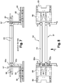
- the machine according to a preferred embodiment of the invention shown in figure 5 comprises a base 2 mounted on wheels and provided with a storage chest 20 for forming rollers, and a frame 3 ensuring the rigidity of the machine, placed on the base 2.
- the bending assembly 7 comprises a bending roller 71 mounted on a carriage 72 movable transversely to the direction of travel and means 73 for adjusting the position of the bending roller 71 movable with respect to the set of rollers finishing forming 62, to be able to adjust the relative position between the bending roller 71 and the top finishing roller 62a with which it cooperates to bend the blank, depending on the desired bending radius.
- the carriage 72 is movable in a direction inclined with respect to the blank plane, so that the bending roll 71 can be positioned as close as possible to the upper finishing roll 62a, which also serves as a blank support roll, for the bending with a minimum bending radius.
- the blank As soon as the blank of the air gap leaves between the finishing rollers, the blank is pushed upwards by the bending roller 71, represented in the high position by the reference 71 'on the figure 6 , which causes the blank 9 to bend with the desired curvature, adjusted by the adjustment in position of the carriage of the bending assembly 7.
- the blank When the blank is fully rolled, it is freed from the grip of the forming rolls and bending, and can be grasped by the operator or a suitable gripping means, ready for use.
Landscapes
- Engineering & Computer Science (AREA)
- Mechanical Engineering (AREA)
- General Engineering & Computer Science (AREA)
- Bending Of Plates, Rods, And Pipes (AREA)
- Metal Rolling (AREA)
Claims (12)
- Verfahren zur Herstellung eines rohrförmigen Wärmeisolierelements (1) aus Metallblech, wobei das Element aus einem gebogenen Blechzuschnitt besteht, dessen zwei gegenüberliegende Längskanten (18, 19) entlang einer Längsverbindungslinie miteinander verbunden sind, wobei das Element eine umlaufende Erhöhung (11, 14, 15, 16) aufweist, die auf dem Blech nur in der Nähe wenigstens eines axialen Endes des Elements, das durch einen Rand (12, 13) des Zuschnitts senkrecht zu den Längskanten gebildet ist, auf dem Umfang des Elements ausgebildet ist, wobei die Erhöhung in ihrer gesamten Dicke auf dem Blech vorgesehen ist, dadurch gekennzeichnet, dass die Erhöhung am Rand (12, 13) des plan gehaltenen und zwischen zwei Formwalzen (62a, 62b) in einer Richtung (F) parallel zum Rand laufangetrieben Blechzuschnitts (9) beim Durchlaufen ausgebildet wird, und anschließend das Biegen des die Erhöhung aufweisenden Zuschnitts mit einer Biegewalze (71) durchgeführt wird, die mit einer der Formwalzen (62a) zusammenwirkt, um den Zuschnitt bei seinem Austritt aus dem Spalt zwischen den Formwalzen unmittelbar im Anschluss an die Ausformung der Erhöhung beim Durchlaufen des Zuschnitts in einem einzigen Arbeitsgang zu biegen.
- Verfahren nach Anspruch 1, wobei die umlaufende Erhöhung in mindestens zwei Formschritten ausgebildet wird, welche einen Vorformschritt und einen Fertigformschritt umfassen, die beim Durchlaufen des Blechs nacheinander ausgeführt werden, wobei jeder Schritt mit einem Satz bestehend aus zwei Formwalzen durchgeführt wird.
- Verfahren nach Anspruch 1, wobei die umlaufende Erhöhung eine vertiefte oder erhabene Leiste aufweist.
- Verfahren nach Anspruch 1, wobei die umlaufende Erhöhung eine Einschnürung oder eine Wellung aufweist.
- Verfahren nach Anspruch 1, wobei der Blechzuschnitt eine Dicke von 0,4 bis 1 mm hat.
- Verfahren nach Anspruch 1, wobei der Blechzuschnitt aus Aluminium, vorlackiertem Stahl, rostfreiem Stahl oder verzinktem Stahl ist.
- Vorrichtung zur Herstellung eines rohrförmigen Wärmeisolierelements aus Metallblech, wobei das Element (1) aus einem gebogenen Blechzuschnitt (9) gebildet ist, dessen zwei gegenüberliegende Längskanten (18, 19) entlang einer Längsverbindungslinie miteinander verbunden sind, wobei das Element eine umlaufende Erhöhung (11, 14, 15, 16) aufweist, die auf dem Blech nur in der Nähe wenigstens eines axialen Endes des Elements auf dem Umfang des Elements ausgebildet ist,
dadurch gekennzeichnet, dass sie nacheinander in einer zur Achse des herzustellenden Wärmeisolierelements senkrechten Durchlaufrichtung umfasst:- eine Antriebsgruppe (5), um den Zuschnitt (9) flach in die Durchlaufrichtung (F) zu transportieren,- eine Formwalzengruppe (61, 62), die Formrollen (65, 66) aufweist, um die Erhöhung am Rand des Zuschnitts auszubilden, und- eine der Formwalzengruppe unmittelbar nachgeschaltete Biegegruppe (7), um den die Erhöhung aufweisenden Zuschnitt zu biegen, wobei die Biegegruppe (7) eine quer zur Durchlaufrichtung (F) bewegliche Biegewalze (71) sowie Mittel (73) zur Einstellung der Position der Biegewalze (71) relativ zu den Formwalzen (62) aufweist. - Vorrichtung nach Anspruch 7, wobei die Formwalzengruppe nacheinander in Durchlaufrichtung einen Satz Vorformwalzen (61) und einen Satz Fertigformwalzen (62) aufweist.
- Vorrichtung nach Anspruch 7, wobei die Formrollen (65, 66) lösbar mit den Enden der Formwalzen (61, 62) verbunden sind.
- Vorrichtung nach Anspruch 7, wobei die Enden der Formwalzen (61, 62) in an querverschieblichen Schlitten (68, 69) angeordneten Lagern (67) gelagert sind, um die Walzenenden für die Austauschbarkeit der Formrollen freigeben zu können und/oder die Verwendung von Walzen unterschiedlicher Längen zu gestatten.
- Vorrichtung nach Anspruch 7, wobei die Biegewalze (71) an einem quer zur Durchlaufrichtung (F) beweglichen Schlitten (72) angeordnet ist.
- Vorrichtung nach Anspruch 7, wobei die Antriebsgruppe (5) einen Satz Klemmwalzen (51) aufweist.
Applications Claiming Priority (2)
| Application Number | Priority Date | Filing Date | Title |
|---|---|---|---|
| LU92442A LU92442B1 (fr) | 2014-05-02 | 2014-05-02 | Procédé de fabrication d'un élément de calorifugeage tubulaire en tôle métalique |
| PCT/EP2015/059585 WO2015166078A1 (fr) | 2014-05-02 | 2015-04-30 | Procédé et dispositif de fabrication d'un élément de calorifugeage tubulaire en tôle metallique |
Publications (2)
| Publication Number | Publication Date |
|---|---|
| EP3137239A1 EP3137239A1 (de) | 2017-03-08 |
| EP3137239B1 true EP3137239B1 (de) | 2018-04-11 |
Family
ID=50877629
Family Applications (1)
| Application Number | Title | Priority Date | Filing Date |
|---|---|---|---|
| EP15724181.1A Active EP3137239B1 (de) | 2014-05-02 | 2015-04-30 | Verfahren und vorrichtung zur herstellung eines rohrförmigen schalungselements aus metallblech |
Country Status (5)
| Country | Link |
|---|---|
| US (1) | US10449586B2 (de) |
| EP (1) | EP3137239B1 (de) |
| CN (1) | CN106470773B (de) |
| LU (1) | LU92442B1 (de) |
| WO (1) | WO2015166078A1 (de) |
Families Citing this family (1)
| Publication number | Priority date | Publication date | Assignee | Title |
|---|---|---|---|---|
| CN109365571B (zh) * | 2018-09-26 | 2024-03-29 | 中建三局第二建设工程有限责任公司 | 风管联合角咬口东洋骨扩缝机 |
Family Cites Families (13)
| Publication number | Priority date | Publication date | Assignee | Title |
|---|---|---|---|---|
| US2569962A (en) * | 1948-04-21 | 1951-10-02 | Bigwood Joshua & Son Ltd | Machine for bending plates |
| US3858785A (en) * | 1971-12-30 | 1975-01-07 | Olin Corp | Apparatus for making heat exchanger tube |
| DE2260475A1 (de) * | 1972-12-11 | 1974-06-12 | Stueckmann & Hillen Gmbh Masch | Blechrundmaschine |
| US3921883A (en) * | 1973-03-21 | 1975-11-25 | Olin Corp | Apparatus for making welded corrugated tube |
| FR2566094B1 (fr) * | 1984-06-14 | 1986-12-05 | Tolerie Ind Sa | Conduit metallique a double paroi pour gaz chauds |
| JPH0646078B2 (ja) * | 1989-05-30 | 1994-06-15 | 株式会社ダクト産業 | 曲管の製造方法 |
| CN2288027Y (zh) * | 1996-10-30 | 1998-08-19 | 中外合资常熟华虞金属软管有限公司 | 铝风管制造机成型机构 |
| EP1213063B1 (de) | 2000-12-04 | 2006-06-07 | Mabi Ag | Sickenmaschine |
| JP4179890B2 (ja) * | 2003-01-30 | 2008-11-12 | 川口工業株式会社 | 溝成形装置 |
| ES2303934T5 (es) | 2003-09-25 | 2012-05-31 | Mabi Ag | Máquina laminadora de chapas para el acanalado, rebordeado y similares de chapas finas |
| CN201154374Y (zh) * | 2007-11-15 | 2008-11-26 | 陈卓平 | 一种冲孔卷圈机 |
| KR20130034298A (ko) * | 2011-09-28 | 2013-04-05 | 한미실업 주식회사 | 코일형상의 금속판 제조를 위한 곡률형성장치 |
| CN202779346U (zh) * | 2012-09-28 | 2013-03-13 | 山东德克鼓风机有限公司 | 背板压型开口一体机 |
-
2014
- 2014-05-02 LU LU92442A patent/LU92442B1/xx active
-
2015
- 2015-04-30 EP EP15724181.1A patent/EP3137239B1/de active Active
- 2015-04-30 US US15/308,580 patent/US10449586B2/en active Active
- 2015-04-30 CN CN201580036277.2A patent/CN106470773B/zh active Active
- 2015-04-30 WO PCT/EP2015/059585 patent/WO2015166078A1/fr not_active Ceased
Also Published As
| Publication number | Publication date |
|---|---|
| EP3137239A1 (de) | 2017-03-08 |
| LU92442B1 (fr) | 2015-11-03 |
| CN106470773A (zh) | 2017-03-01 |
| US10449586B2 (en) | 2019-10-22 |
| CN106470773B (zh) | 2019-06-21 |
| WO2015166078A1 (fr) | 2015-11-05 |
| US20170072445A1 (en) | 2017-03-16 |
Similar Documents
| Publication | Publication Date | Title |
|---|---|---|
| FR2878769A1 (fr) | Procede et dispositif de fabrication de tuyau rainure, et structure de celui-ci | |
| CN102794606A (zh) | 一种铜管制备方法及实施该方法的制管机 | |
| FR2467683A1 (fr) | Procede et appareil pour la fabrication d'un materiau elastomerique en feuille par extrusion | |
| CA1293845C (fr) | Procede et dispositif pour la realisation de gorges sur une paroi de revolution | |
| EP3137239B1 (de) | Verfahren und vorrichtung zur herstellung eines rohrförmigen schalungselements aus metallblech | |
| CN101312796B (zh) | 用于对卷材连续穿孔和形成管材的设备及方法 | |
| KR20080111951A (ko) | 박판의 강판부재를 이용한 관 제조용 용접가스 제거장치와이를 이용한 관 제조장치 및 그 제조방법 | |
| EP0198779B1 (de) | Zieheisenvorrichtung zum Formen von Rohren aus einem Metallband | |
| FR2690858A1 (fr) | Dispositif permettant le formage d'ailettes hélicoïdales sur la paroi extérieure de tubes. | |
| JP6684634B2 (ja) | 鋼管製造設備及び鋼管製造方法 | |
| WO2009106630A1 (fr) | Procede de fabrication d'une ailette et dispositif pour la mise en oeuvre d'un tel procede | |
| US20120186318A1 (en) | Device for rolling threads | |
| BE553598A (de) | ||
| FR2509203A1 (fr) | Procede de fabrication d'un coude tubulaire | |
| KR100891737B1 (ko) | 직관 연결용 소켓장치 | |
| BE1004786A3 (fr) | Appareil pour fabriquer un tube ondule. | |
| EP0721558A1 (de) | Abstandselement für eine aufstapelung, verfahren zu seiner herstellung und maschine zur durchführung des verfahrens | |
| FR2588201A1 (fr) | Procede, installation et train de laminage pour la fabrication de tubes sans soudure | |
| JP2008296273A (ja) | 単管ロール造管装置及び単管ロールの造管方法 | |
| WO2020021165A1 (fr) | Trame hydraulique préformée et prête a poser pour planchers et murs chauffants, ses procédé et dispositif de fabrication | |
| EP0013653A1 (de) | Vorrichtung zur Herstellung gebogener Winkeleisen | |
| BE571608A (de) | ||
| CH326645A (fr) | Machine pour fabriquer un tube | |
| BE491578A (de) | ||
| CH383617A (fr) | Procédé pour la fabrication d'un joint d'étanchéité annulaire de grand diamètre, appareillage pour la mise en oeuvre de ce procédé et joint obtenu par ce procédé |
Legal Events
| Date | Code | Title | Description |
|---|---|---|---|
| PUAI | Public reference made under article 153(3) epc to a published international application that has entered the european phase |
Free format text: ORIGINAL CODE: 0009012 |
|
| 17P | Request for examination filed |
Effective date: 20161027 |
|
| AK | Designated contracting states |
Kind code of ref document: A1 Designated state(s): AL AT BE BG CH CY CZ DE DK EE ES FI FR GB GR HR HU IE IS IT LI LT LU LV MC MK MT NL NO PL PT RO RS SE SI SK SM TR |
|
| AX | Request for extension of the european patent |
Extension state: BA ME |
|
| DAV | Request for validation of the european patent (deleted) | ||
| DAX | Request for extension of the european patent (deleted) | ||
| GRAP | Despatch of communication of intention to grant a patent |
Free format text: ORIGINAL CODE: EPIDOSNIGR1 |
|
| INTG | Intention to grant announced |
Effective date: 20171025 |
|
| GRAS | Grant fee paid |
Free format text: ORIGINAL CODE: EPIDOSNIGR3 |
|
| GRAA | (expected) grant |
Free format text: ORIGINAL CODE: 0009210 |
|
| AK | Designated contracting states |
Kind code of ref document: B1 Designated state(s): AL AT BE BG CH CY CZ DE DK EE ES FI FR GB GR HR HU IE IS IT LI LT LU LV MC MK MT NL NO PL PT RO RS SE SI SK SM TR |
|
| REG | Reference to a national code |
Ref country code: GB Ref legal event code: FG4D Free format text: NOT ENGLISH |
|
| REG | Reference to a national code |
Ref country code: CH Ref legal event code: EP |
|
| REG | Reference to a national code |
Ref country code: AT Ref legal event code: REF Ref document number: 987445 Country of ref document: AT Kind code of ref document: T Effective date: 20180415 |
|
| REG | Reference to a national code |
Ref country code: IE Ref legal event code: FG4D Free format text: LANGUAGE OF EP DOCUMENT: FRENCH |
|
| REG | Reference to a national code |
Ref country code: DE Ref legal event code: R096 Ref document number: 602015009902 Country of ref document: DE |
|
| REG | Reference to a national code |
Ref country code: FR Ref legal event code: PLFP Year of fee payment: 4 |
|
| REG | Reference to a national code |
Ref country code: CH Ref legal event code: NV Representative=s name: OFFICE ERNEST T. FREYLINGER S.A., CH |
|
| REG | Reference to a national code |
Ref country code: NL Ref legal event code: MP Effective date: 20180411 |
|
| REG | Reference to a national code |
Ref country code: LT Ref legal event code: MG4D |
|
| PG25 | Lapsed in a contracting state [announced via postgrant information from national office to epo] |
Ref country code: NL Free format text: LAPSE BECAUSE OF FAILURE TO SUBMIT A TRANSLATION OF THE DESCRIPTION OR TO PAY THE FEE WITHIN THE PRESCRIBED TIME-LIMIT Effective date: 20180411 |
|
| PG25 | Lapsed in a contracting state [announced via postgrant information from national office to epo] |
Ref country code: ES Free format text: LAPSE BECAUSE OF FAILURE TO SUBMIT A TRANSLATION OF THE DESCRIPTION OR TO PAY THE FEE WITHIN THE PRESCRIBED TIME-LIMIT Effective date: 20180411 Ref country code: SE Free format text: LAPSE BECAUSE OF FAILURE TO SUBMIT A TRANSLATION OF THE DESCRIPTION OR TO PAY THE FEE WITHIN THE PRESCRIBED TIME-LIMIT Effective date: 20180411 Ref country code: AL Free format text: LAPSE BECAUSE OF FAILURE TO SUBMIT A TRANSLATION OF THE DESCRIPTION OR TO PAY THE FEE WITHIN THE PRESCRIBED TIME-LIMIT Effective date: 20180411 Ref country code: BG Free format text: LAPSE BECAUSE OF FAILURE TO SUBMIT A TRANSLATION OF THE DESCRIPTION OR TO PAY THE FEE WITHIN THE PRESCRIBED TIME-LIMIT Effective date: 20180711 Ref country code: NO Free format text: LAPSE BECAUSE OF FAILURE TO SUBMIT A TRANSLATION OF THE DESCRIPTION OR TO PAY THE FEE WITHIN THE PRESCRIBED TIME-LIMIT Effective date: 20180711 Ref country code: FI Free format text: LAPSE BECAUSE OF FAILURE TO SUBMIT A TRANSLATION OF THE DESCRIPTION OR TO PAY THE FEE WITHIN THE PRESCRIBED TIME-LIMIT Effective date: 20180411 Ref country code: LT Free format text: LAPSE BECAUSE OF FAILURE TO SUBMIT A TRANSLATION OF THE DESCRIPTION OR TO PAY THE FEE WITHIN THE PRESCRIBED TIME-LIMIT Effective date: 20180411 Ref country code: PL Free format text: LAPSE BECAUSE OF FAILURE TO SUBMIT A TRANSLATION OF THE DESCRIPTION OR TO PAY THE FEE WITHIN THE PRESCRIBED TIME-LIMIT Effective date: 20180411 |
|
| PG25 | Lapsed in a contracting state [announced via postgrant information from national office to epo] |
Ref country code: HR Free format text: LAPSE BECAUSE OF FAILURE TO SUBMIT A TRANSLATION OF THE DESCRIPTION OR TO PAY THE FEE WITHIN THE PRESCRIBED TIME-LIMIT Effective date: 20180411 Ref country code: GR Free format text: LAPSE BECAUSE OF FAILURE TO SUBMIT A TRANSLATION OF THE DESCRIPTION OR TO PAY THE FEE WITHIN THE PRESCRIBED TIME-LIMIT Effective date: 20180712 Ref country code: LV Free format text: LAPSE BECAUSE OF FAILURE TO SUBMIT A TRANSLATION OF THE DESCRIPTION OR TO PAY THE FEE WITHIN THE PRESCRIBED TIME-LIMIT Effective date: 20180411 Ref country code: RS Free format text: LAPSE BECAUSE OF FAILURE TO SUBMIT A TRANSLATION OF THE DESCRIPTION OR TO PAY THE FEE WITHIN THE PRESCRIBED TIME-LIMIT Effective date: 20180411 |
|
| REG | Reference to a national code |
Ref country code: AT Ref legal event code: MK05 Ref document number: 987445 Country of ref document: AT Kind code of ref document: T Effective date: 20180411 |
|
| PG25 | Lapsed in a contracting state [announced via postgrant information from national office to epo] |
Ref country code: PT Free format text: LAPSE BECAUSE OF FAILURE TO SUBMIT A TRANSLATION OF THE DESCRIPTION OR TO PAY THE FEE WITHIN THE PRESCRIBED TIME-LIMIT Effective date: 20180813 |
|
| REG | Reference to a national code |
Ref country code: DE Ref legal event code: R097 Ref document number: 602015009902 Country of ref document: DE |
|
| REG | Reference to a national code |
Ref country code: IE Ref legal event code: MM4A |
|
| PG25 | Lapsed in a contracting state [announced via postgrant information from national office to epo] |
Ref country code: MC Free format text: LAPSE BECAUSE OF FAILURE TO SUBMIT A TRANSLATION OF THE DESCRIPTION OR TO PAY THE FEE WITHIN THE PRESCRIBED TIME-LIMIT Effective date: 20180411 Ref country code: RO Free format text: LAPSE BECAUSE OF FAILURE TO SUBMIT A TRANSLATION OF THE DESCRIPTION OR TO PAY THE FEE WITHIN THE PRESCRIBED TIME-LIMIT Effective date: 20180411 Ref country code: CZ Free format text: LAPSE BECAUSE OF FAILURE TO SUBMIT A TRANSLATION OF THE DESCRIPTION OR TO PAY THE FEE WITHIN THE PRESCRIBED TIME-LIMIT Effective date: 20180411 Ref country code: EE Free format text: LAPSE BECAUSE OF FAILURE TO SUBMIT A TRANSLATION OF THE DESCRIPTION OR TO PAY THE FEE WITHIN THE PRESCRIBED TIME-LIMIT Effective date: 20180411 Ref country code: AT Free format text: LAPSE BECAUSE OF FAILURE TO SUBMIT A TRANSLATION OF THE DESCRIPTION OR TO PAY THE FEE WITHIN THE PRESCRIBED TIME-LIMIT Effective date: 20180411 Ref country code: SK Free format text: LAPSE BECAUSE OF FAILURE TO SUBMIT A TRANSLATION OF THE DESCRIPTION OR TO PAY THE FEE WITHIN THE PRESCRIBED TIME-LIMIT Effective date: 20180411 Ref country code: LU Free format text: LAPSE BECAUSE OF NON-PAYMENT OF DUE FEES Effective date: 20180430 Ref country code: DK Free format text: LAPSE BECAUSE OF FAILURE TO SUBMIT A TRANSLATION OF THE DESCRIPTION OR TO PAY THE FEE WITHIN THE PRESCRIBED TIME-LIMIT Effective date: 20180411 |
|
| PLBE | No opposition filed within time limit |
Free format text: ORIGINAL CODE: 0009261 |
|
| STAA | Information on the status of an ep patent application or granted ep patent |
Free format text: STATUS: NO OPPOSITION FILED WITHIN TIME LIMIT |
|
| PG25 | Lapsed in a contracting state [announced via postgrant information from national office to epo] |
Ref country code: SM Free format text: LAPSE BECAUSE OF FAILURE TO SUBMIT A TRANSLATION OF THE DESCRIPTION OR TO PAY THE FEE WITHIN THE PRESCRIBED TIME-LIMIT Effective date: 20180411 |
|
| 26N | No opposition filed |
Effective date: 20190114 |
|
| PG25 | Lapsed in a contracting state [announced via postgrant information from national office to epo] |
Ref country code: IE Free format text: LAPSE BECAUSE OF NON-PAYMENT OF DUE FEES Effective date: 20180430 |
|
| PG25 | Lapsed in a contracting state [announced via postgrant information from national office to epo] |
Ref country code: SI Free format text: LAPSE BECAUSE OF FAILURE TO SUBMIT A TRANSLATION OF THE DESCRIPTION OR TO PAY THE FEE WITHIN THE PRESCRIBED TIME-LIMIT Effective date: 20180411 |
|
| PG25 | Lapsed in a contracting state [announced via postgrant information from national office to epo] |
Ref country code: MT Free format text: LAPSE BECAUSE OF FAILURE TO SUBMIT A TRANSLATION OF THE DESCRIPTION OR TO PAY THE FEE WITHIN THE PRESCRIBED TIME-LIMIT Effective date: 20180411 |
|
| PG25 | Lapsed in a contracting state [announced via postgrant information from national office to epo] |
Ref country code: TR Free format text: LAPSE BECAUSE OF FAILURE TO SUBMIT A TRANSLATION OF THE DESCRIPTION OR TO PAY THE FEE WITHIN THE PRESCRIBED TIME-LIMIT Effective date: 20180411 |
|
| PG25 | Lapsed in a contracting state [announced via postgrant information from national office to epo] |
Ref country code: CY Free format text: LAPSE BECAUSE OF FAILURE TO SUBMIT A TRANSLATION OF THE DESCRIPTION OR TO PAY THE FEE WITHIN THE PRESCRIBED TIME-LIMIT Effective date: 20180411 Ref country code: HU Free format text: LAPSE BECAUSE OF FAILURE TO SUBMIT A TRANSLATION OF THE DESCRIPTION OR TO PAY THE FEE WITHIN THE PRESCRIBED TIME-LIMIT; INVALID AB INITIO Effective date: 20150430 Ref country code: MK Free format text: LAPSE BECAUSE OF NON-PAYMENT OF DUE FEES Effective date: 20180411 |
|
| PG25 | Lapsed in a contracting state [announced via postgrant information from national office to epo] |
Ref country code: IS Free format text: LAPSE BECAUSE OF FAILURE TO SUBMIT A TRANSLATION OF THE DESCRIPTION OR TO PAY THE FEE WITHIN THE PRESCRIBED TIME-LIMIT Effective date: 20180811 |
|
| P01 | Opt-out of the competence of the unified patent court (upc) registered |
Free format text: CASE NUMBER: APP_41038/2024 Effective date: 20240710 |
|
| PGFP | Annual fee paid to national office [announced via postgrant information from national office to epo] |
Ref country code: BE Payment date: 20250324 Year of fee payment: 11 |
|
| PGFP | Annual fee paid to national office [announced via postgrant information from national office to epo] |
Ref country code: FR Payment date: 20250324 Year of fee payment: 11 |
|
| PGFP | Annual fee paid to national office [announced via postgrant information from national office to epo] |
Ref country code: GB Payment date: 20250324 Year of fee payment: 11 |
|
| PGFP | Annual fee paid to national office [announced via postgrant information from national office to epo] |
Ref country code: DE Payment date: 20250324 Year of fee payment: 11 |
|
| PGFP | Annual fee paid to national office [announced via postgrant information from national office to epo] |
Ref country code: IT Payment date: 20250401 Year of fee payment: 11 |
|
| PGFP | Annual fee paid to national office [announced via postgrant information from national office to epo] |
Ref country code: CH Payment date: 20250501 Year of fee payment: 11 |