EP3137160B1 - A device for inactivating bacteria - Google Patents
A device for inactivating bacteria Download PDFInfo
- Publication number
- EP3137160B1 EP3137160B1 EP15720065.0A EP15720065A EP3137160B1 EP 3137160 B1 EP3137160 B1 EP 3137160B1 EP 15720065 A EP15720065 A EP 15720065A EP 3137160 B1 EP3137160 B1 EP 3137160B1
- Authority
- EP
- European Patent Office
- Prior art keywords
- electrodes
- plane
- electrical field
- stratum corneum
- skin
- Prior art date
- Legal status (The legal status is an assumption and is not a legal conclusion. Google has not performed a legal analysis and makes no representation as to the accuracy of the status listed.)
- Active
Links
Images


Classifications
-
- A—HUMAN NECESSITIES
- A61—MEDICAL OR VETERINARY SCIENCE; HYGIENE
- A61N—ELECTROTHERAPY; MAGNETOTHERAPY; RADIATION THERAPY; ULTRASOUND THERAPY
- A61N1/00—Electrotherapy; Circuits therefor
- A61N1/02—Details
- A61N1/04—Electrodes
- A61N1/0404—Electrodes for external use
- A61N1/0408—Use-related aspects
-
- A—HUMAN NECESSITIES
- A61—MEDICAL OR VETERINARY SCIENCE; HYGIENE
- A61L—METHODS OR APPARATUS FOR STERILISING MATERIALS OR OBJECTS IN GENERAL; DISINFECTION, STERILISATION OR DEODORISATION OF AIR; CHEMICAL ASPECTS OF BANDAGES, DRESSINGS, ABSORBENT PADS OR SURGICAL ARTICLES; MATERIALS FOR BANDAGES, DRESSINGS, ABSORBENT PADS OR SURGICAL ARTICLES
- A61L2/00—Methods or apparatus for disinfecting or sterilising materials or objects other than foodstuffs or contact lenses; Accessories therefor
- A61L2/0005—Methods or apparatus for disinfecting or sterilising materials or objects other than foodstuffs or contact lenses; Accessories therefor for pharmaceuticals, biologicals or living parts
- A61L2/0011—Methods or apparatus for disinfecting or sterilising materials or objects other than foodstuffs or contact lenses; Accessories therefor for pharmaceuticals, biologicals or living parts using physical methods
-
- A—HUMAN NECESSITIES
- A61—MEDICAL OR VETERINARY SCIENCE; HYGIENE
- A61L—METHODS OR APPARATUS FOR STERILISING MATERIALS OR OBJECTS IN GENERAL; DISINFECTION, STERILISATION OR DEODORISATION OF AIR; CHEMICAL ASPECTS OF BANDAGES, DRESSINGS, ABSORBENT PADS OR SURGICAL ARTICLES; MATERIALS FOR BANDAGES, DRESSINGS, ABSORBENT PADS OR SURGICAL ARTICLES
- A61L2/00—Methods or apparatus for disinfecting or sterilising materials or objects other than foodstuffs or contact lenses; Accessories therefor
- A61L2/02—Methods or apparatus for disinfecting or sterilising materials or objects other than foodstuffs or contact lenses; Accessories therefor using physical phenomena
- A61L2/03—Electric current
-
- A—HUMAN NECESSITIES
- A61—MEDICAL OR VETERINARY SCIENCE; HYGIENE
- A61N—ELECTROTHERAPY; MAGNETOTHERAPY; RADIATION THERAPY; ULTRASOUND THERAPY
- A61N1/00—Electrotherapy; Circuits therefor
- A61N1/02—Details
- A61N1/04—Electrodes
- A61N1/0404—Electrodes for external use
- A61N1/0408—Use-related aspects
- A61N1/0412—Specially adapted for transcutaneous electroporation, e.g. including drug reservoirs
-
- A—HUMAN NECESSITIES
- A61—MEDICAL OR VETERINARY SCIENCE; HYGIENE
- A61N—ELECTROTHERAPY; MAGNETOTHERAPY; RADIATION THERAPY; ULTRASOUND THERAPY
- A61N1/00—Electrotherapy; Circuits therefor
- A61N1/18—Applying electric currents by contact electrodes
- A61N1/20—Applying electric currents by contact electrodes continuous direct currents
- A61N1/30—Apparatus for iontophoresis, i.e. transfer of media in ionic state by an electromotoric force into the body, or cataphoresis
-
- A—HUMAN NECESSITIES
- A61—MEDICAL OR VETERINARY SCIENCE; HYGIENE
- A61N—ELECTROTHERAPY; MAGNETOTHERAPY; RADIATION THERAPY; ULTRASOUND THERAPY
- A61N1/00—Electrotherapy; Circuits therefor
- A61N1/18—Applying electric currents by contact electrodes
- A61N1/32—Applying electric currents by contact electrodes alternating or intermittent currents
- A61N1/325—Applying electric currents by contact electrodes alternating or intermittent currents for iontophoresis, i.e. transfer of media in ionic state by an electromotoric force into the body
-
- A—HUMAN NECESSITIES
- A61—MEDICAL OR VETERINARY SCIENCE; HYGIENE
- A61N—ELECTROTHERAPY; MAGNETOTHERAPY; RADIATION THERAPY; ULTRASOUND THERAPY
- A61N1/00—Electrotherapy; Circuits therefor
- A61N1/18—Applying electric currents by contact electrodes
- A61N1/32—Applying electric currents by contact electrodes alternating or intermittent currents
- A61N1/327—Applying electric currents by contact electrodes alternating or intermittent currents for enhancing the absorption properties of tissue, e.g. by electroporation
-
- C—CHEMISTRY; METALLURGY
- C12—BIOCHEMISTRY; BEER; SPIRITS; WINE; VINEGAR; MICROBIOLOGY; ENZYMOLOGY; MUTATION OR GENETIC ENGINEERING
- C12N—MICROORGANISMS OR ENZYMES; COMPOSITIONS THEREOF; PROPAGATING, PRESERVING, OR MAINTAINING MICROORGANISMS; MUTATION OR GENETIC ENGINEERING; CULTURE MEDIA
- C12N13/00—Treatment of microorganisms or enzymes with electrical or wave energy, e.g. magnetism, sonic waves
Definitions
- the present invention relates to a device for inactivating bacteria.
- a method of manufacturing such a device is also disclosed.
- Human skin has two broad tissue types, the epidermis and the dermis.
- the epidermis is a continually keratinizing stratified epithelium.
- the outermost layer of skin is the stratum corneum and functions as the primary barrier.
- the stratum corneum is the outermost layer of the epidermidis and varies in thickness as function of the skin location. For example in the hand palm this layer can reach a thickness of 300 micron while the thickness in the armpit is approximatetly 5 to 15 micron.
- the stratum corneum is 15-30 cell thick layer of non-viable corneocytes.
- Electroporation of cells is a non-thermal technique in which electrical fields are used to create nano-scale defects in a cell's membrane, which may cause cell inactivity or death. Electroporation involves the application of brief electrical pulses that result in the creation of aqueous pathways within the lipid bi-layer membranes of biological cells. Electroporation depends on the local transmembrane voltage at each point on the cell membrane. It is generally accepted that for a given pulse duration and shape, a specific transmembrane voltage threshold exists for the manifestation of the electroporation phenomenon. This leads to the definition of an electric field magnitude threshold for electroporation (E th ). That is, only the cells within areas where E ⁇ E th are electroporated. If a second threshold (E ir ) is reached or surpassed, electroporation will compromise the viability of the cells, i.e., irreversible electroporation will occur.
- E th electric field magnitude threshold for electroporation
- Sweat contains salt ions typically in the order of 4.5 g/L Sodium Chloride.
- a dermal electroporation device is known from WO2013066427A and primarily relates to the use of electroporation for the purpose of delivering drugs to dermal tissue.
- US2007060862A2 also discloses a transdermal delivery device in which the electrodes are used to control a current flow through the skin.
- US patent number 6,711,435 B2 discloses a device for transdermal drug derlivery and analyte extraction which is configured to ablate the stratum corneum.
- a device according to this document has multiple electroded touching the stratum corneum.
- US published patent application number 2013/0260435 A1 discloses a method of enhancing membrane permeabilization in a cell. It is disclosed in this document that the electrodes are to generate an electromagnetic field causing intracellular ions to leave living cells and to cause (sub-skin) tumor cells death.
- US patent number 5,968,006 discloses an apparatus and method for transdermal drug delivery using two electrode assemblies connected to a power supply. During use the devcie according to this patent is to induce migration of molecules through pores in the stratum corneum.
- US published patent application number 2004/230227 A1 discloses a device for transdermal drug delivery comprising a plurality of electrodes which are placed in contact with the skin.
- the device of the invention can be used to decrease body odour caused by the presence of such bacteria on the skin surface, i.e. on the stratum corneum, such as the bacteria found in the axilla region of the body.
- bacteria can be present in the glands as well as on the stratum corneum, it is thought that the bacteria on the skin surface is primarily responsible for the majority of malodour, since the secretions of glands are initially odourless. Therefore, it is the bacteria present on the skin surface, i.e. on the stratum corneum, which is the primary target for treatment by the device and method of the present invention.
- the "inactivation" of bacteria refers to the death or slowing of the metabolic rate and/or reproduction system of the bacterial cells.
- a device for the electroporation of bacterial cells present on the surface of the stratum corneum layer of a person's skin comprising:
- the electrical field strength will generally only have sufficient strength to inactivate bacteria cells present on the stratum corneum and, at least to some extent, those bacterial cells present within the stratum corneum. However, the electrical field strength will not be high enough to have any appreciable effect on living skin cells in the epidermis below the stratum corneum or at the interface between the stratum corneum and the epidermis.
- the electrodes preferably comprise at least one positive and at least one negative electrode, the positive and negative electrodes being in the same plane and being spaced from each other by a predetermined distance to control the strength of the electrical field at a predetermined penetration depth of between 5 and 10 micron.
- the strength of the electrical field at a predetermined depth of penetration can be controlled in order to reduce any effect of the electrical field on living tissue.
- the positive and negative electrodes may be spaced from each other by a distance of 10 micron or less.
- a separation distance of less than or equal to 10 micron can be considered to be an optimum distance in relation to an average thickness of the stratum comeum, with the aim of ensuring that the electrical field strength at the interface between the stratum corneum and the epidermis is at or below 3kV/cm. It is also envisaged that the electrodes could be separated by 5 micron to provide an electrical field strength below 3kV/cm at a penetration depth of 8 micron.
- the device comprises a plurality of positive and negative electrodes, wherein the positive electrodes are positioned in a first plane and the negative electrodes are position in a second plane adjacent to the first plane.
- the electrodes in the first plane and the electrodes in the second plane can be in alignment with each other, and the electrodes in each plane may be separated from each other by a distance of 10 microns or less.
- the electrodes in the first plane and the electrodes in the second plane are offset relative to each other so that an electrode in one plane is located between a pair of electrodes in the other plane. This arrangement can provide an even steeper reduction in the electrical field strength with penetration depth.
- the electrode elements in different planes may be isolated from each other by an isolating element.
- the electrodes may also be provided with sharpened edges in order to further control the shape and spread of the electical field.
- the generator is operable to supply the electrodes with a pulsed voltage of 10 to 1000 pulses, each pulse have a duration of 1 to 100 microseconds or, more preferably, 50 pulses of 50 microseconds each. It will be appreciated that for a small device that is moved across the surface of the skin in the axilla region, a device capable of generating a higher number of pulses will be required if the treatment time is to be kept within a reasonable period and the axilla is to be treated effectively. By administering a particular Voltage over time profile, activation of the nerves can be prevented. More specifically, a sufficiently high frequency of pulses is used which does not activate the nerves but which is not too high that blockage of nerves occurs.
- the electrodes may be attached to a supporting substrate in the form of a sphere, cylinder or planar element. If the supporting substrate is a sphere or cylinder, then it may be rotatably mounted to the housing so that it will roll over the surface of the stratum corneum.
- a rolling element such as sphere or cylinder, maintains a smooth, low friction contact with the skin surface thereby maximising contact between the electrodes and the surface.
- the electrodes comprise a plurality of electrode arrays. At least one electrode array may extend in a different direction to at least one other electrode array to generate electrical fields of different orientations. This ensures that non-spherical bacterial cells are properly exposed to the electrical field.
- the device may also comprise a hydrodynamic probe to supply fluid of low conductivity to the surface of the stratum corneum in the vicinity of the electrodes.
- the hydrodynamic probe can be used to supply water or other fluid to the skin surface to control conductivity and/or cooling.
- the generator is configured to supply a voltage to the electrodes to generate an electrical field having a strength in the order of 25 to 35 kV/cm on the surface of the stratum corneum.
- the voltage driver circuit includes an electrical current limiter to suppress current levels and thereby prevent activation of nerves.
- an electric field based device used to combat body odour primary aimed at, but not limited to, treating axillae.
- the device is preferably either portable or attachable to the skin in the form of a patch/textile etc. and is battery powered.
- the device comprises an intermittent electrode array on which a voltage profile over time is enforced to induce an electrical field.
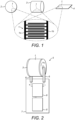
- Fig. 1 illustrates an enlarged view of a suitable intermittent electrode structure or array 1, having a positive electrode 1a and a negative electrode 1b, which can be attached to the surface of three differently shaped bodies namely, a sphere 2 (see Fig. 1a), a cylinder 3 (see Fig. 1b) and a planar or sheet-like element 4 (see Fig. 1c).
- Fig. 2 shows a schematic illustration of a hand-held device 5 incorporating the cylindrical electrode, as shown in Fig. 1 , and which is mounted for rotation about its longitudinal axis between arms 6, so that it will roll freely across a skin surface during use with minimum friction.
- Device 5 includes a housing 7 containing a power source, such as a battery 8, and a generator 9 for supplying the electrodes 1 with a predetermined voltage as a function of time so that, when the cylinder 3, to which the intermittent electrode array 1 is attached, is rolled across the skin surface, an electrical field is induced in the skin surface and electroporation is conducted to inactivate bacterial cells.
- the device 5 may also incorporate an electronic timer (not shown) indicating and limiting the time of use per treatment.
- the device 5 may also contain circuitry to facilitate recharging of the battery.
- the electronics and battery are sealed within the housing 6 so that the device 5 can be cleaned easily by a surfactant solution or by holding it under a tap.
- the device 5 will also incorporate a pressure sensitive switch (not shown) so that the electrodes 1a, 1b will automatically activate when the device is pushed against the skin and deactivate when the device 5 is taken out of contact with the skin.
- a pressure sensitive switch not shown
- it can be provided with a conventional on/off switch.
- the device 5 may be provided with a construction that spaces the electrodes 1a, 1b from the skin surface when the device is held against it. Further, if the intermittent electrode array 1 is positioned on a sphere or cylinder 3 that can freely rotate due to the friction with the skin, the skin is stretched and any surface roughness, which can decrease the efficacy of bacteria inactivation, is smoothed out. Whilst it is desirable to inactivate as much of the bacteria as possible, it will also be appreciated that it is unnecessary for all the bacteria present on the skin surface to be inactivated, but that a log reduction of the bacteria in the order of 1 to 3 is sufficient.
- embodiments may comprise features to flatten the skin such as stretchers, lubra strips and lamella etc, either together with one of the structures shown in Fig. 1 , or formed in some other shape or configuration.
- a lamella structure is moved over the skin under slight pressure the skin will dome between the lamella and will be pushed against the electrodes 1a,1b located on the surface of the lamella in a smooth manner, thereby minimizing skin surface roughness during contact with the electrodes 1a,1b.
- An intermittent electrode array 1 formed on or integrated with a lamella type structure can also increase the degree of contact between the skin and the electrodes 1a,1b thereby reducing any interference caused by the presence of hair.
- a more intimate contact may also be achieved by incorporating a vacuum circuit into the device which is operable to apply a mild vacuum, possibly via the lamella structure, or to the skin in the vicinity of the electrodes 1a,1b, to suck the skin towards the electrodes 1a,1b.
- a vacuum circuit operable to apply a mild vacuum, possibly via the lamella structure, or to the skin in the vicinity of the electrodes 1a,1b, to suck the skin towards the electrodes 1a,1b.
- the electrode array 1 could also be positioned on the surface of a hair-comb that can be moved through the armpit hair so that its extremities will make contact with the skin.
- the device 5 can incorporate a conductivity detector (not shown). If so, the device 5 can initially be held with the electrodes 1a,1b positioned against, or close to, the skin and the detector can measure the conductivity at the skin surface. The detector may be coupled to the generator 9 so that it will generate a voltage commensurate with the required electrical field strength required based on the sensed conductivity of the skin. Once this sensing step has been completed, electroporation may then be carried out using the device 5.
- a conductivity detector not shown. If so, the device 5 can initially be held with the electrodes 1a,1b positioned against, or close to, the skin and the detector can measure the conductivity at the skin surface. The detector may be coupled to the generator 9 so that it will generate a voltage commensurate with the required electrical field strength required based on the sensed conductivity of the skin. Once this sensing step has been completed, electroporation may then be carried out using the device 5.
- a voltage profile over time of 10 to 1000 pulses each of 1 to 100 microseconds in duration is preferably required or, more preferably, 50 pulses each of 50 microseconds in duration.
- the ideal electrical field strength for inactivating bacteria is in the order of 30 kV/cm, although the generator may be capable of supplying the electrodes with a voltage sufficient to generate an electrical field strength of between 10kV/cm and 50kV/cm at the surface of the stratum corneum, although most preferably, the generator is configured to supply the electrodes with a voltage sufficient to generate an electrical field strenght of between 25kV/cm and 35kV/cm at the surface of the stratum corneum. In order to generate a field strength of between 25kV/cm and 35kV/cm at the surface of the stratum corneum using a voltage of 30kV, the electrodes must be 1cm apart.
- the required voltage drops down to about 600 Volts, for an electrode separation distance of 30 micron, the required voltage is about 90 Volts and when the electrode separation distance is 10 micron, the required voltage is about 30 Volts.
- the device may also incorporate an electrical current limiter (not shown). Consequently, the above mentioned voltages are manageable and electrical currents through the body will be way below any level that could cause bodily harm.
- Fig. 3 is a schematic representation of a part of an intermittent electrode array 10 with electrodes positioned in different directions in order to generate electrical fields in different orientations. More specifically, Fig. 3 shows two central arrays 10a, 10b extending in a horizontal direction and two vertical arrays 10c, 10d. A vertical array 10c, 10d extends across the ends of the two central arrays 10a, 10b.
- the electrical field strength has to drop over the stratum corneum from 30 kV/cm to about 3 kV/cm, as mentioned above.
- the electrodes are constructed in a particular way. Possible electrode configurations will now be described in more detail, with reference to Figs. 4a to 4g and Fig. 5 .
- Fig. 4a schematically illustrates a cross-section approximated drawing of the electrical field lines 11 extending between a positive electrode 12a and negative electrode 12b of an intermittent electrode array in which the electrodes 12a, 12b are mounted to a support 13 and are spaced from the skin surface, by sweat or air, which forms a gap 14.
- a field strength of about 30kV/cm is required, whilst the field strength at the interface 16 between the stratum corneum layer 15 and the immediately adjacent layer of the epidermis 17 shown by the field line indicated by numeral "7” should be about 3kV/cm.
- a bacterial cell 18 is shown on the surface 15a of the stratum corneum 15 and lies within the field strength line indicated by reference numeral "2", so it will become inactivated by the electrical field generated between the electrodes 12a, 12b.
- Fig. 4b illustrates the electrode array in more detail in order to show the pitch and the gap between adjacent electrodes mounted to a supporting structure 13.
- the gap between adjacent electrodes 12a, 12b is represented by arrow "X"
- the pitch distance i.e. the distance between adjacent electrode centres is indicated by arrow "Y”.
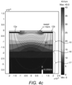
- Fig. 4c is a graph to illustrate the electrical field strength generated through the stratum corneum and the epidermis as a result of placing electrodes adjacent to the surface of the stratum corneum and separated therefrom only by a small layer of sweat present on the skin surface.
- the electrical field strength on the skin surface is approximately 25kV/cm, sufficient to inactivate bacteria.
- the graph shows that, with a gap of 20 micron between the electrodes, the electrical field strength at the interface 16 of the stratum corneum 15 and the next layer of the epidermis 17 is well above 3 kV/cm.
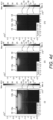
- Fig. 4d is a series of three graphs to illustrate how the electrical field strength over the thickness of the stratum comeum decreases, whereas the electrical field strength on the skin between the electrodes 12a, 12b increases, as the gap between the electrodes 12a, 12b decreases, and assuming that the voltage is maintained a constant level over the electrodes 12a, 12b.
- Fig. 4d (i) represents the electrical field strength at a gap distance of 20micron
- Fig. 4d (ii) represents the electrical field strength at a gap distance of 10micron
- Fig. 4d (iii) represents the electrical field strength at a gap distance of 5micron.
- an isolator coating can be positioned on top of the electrodes, i.e. between the electrodes and the surface of the stratum corneum 15. The presence of this isolator can also have an effect on the strength of the electrical field.
- the electrical field strength is only below 3 kV/cm when the gap between the electrodes 12a, 12b is 5 microns and so this is relevant for treating an area of the skin that has a thinner stratum comeum 15.
- the thickness of the stratum corneum 15 can generally be assumed to be 15 micron, the stratum corneum 15 thickness does vary for the different locations of the skin.
- the stratum corneum 15 thickness in the palms may be in the order of a few hundreds of microns, while in the axilla it can be in the order of 5 to 15 microns.
- the inventors have devised other electrode structures for the purpose of treating areas of the skin where the stratum corneum 15 is thinner and which provide an even larger drop of in the electrical field strength over the stratum corneum 15.
- Fig. 4f is a graph to illustrate the electrical field strength generated through the stratum corneum 15 and the epidermis 17 as a result of placing electrodes 12a, 12b adjacent to the surface 15a of the stratum corneum 15, but in which the positive electrodes 12a are located in a different plane to the negative electrodes 12b.
- the negative electrodes 12b are positioned closest to the surface 15a of the stratum corneum 15, and separated only therefrom by a thin layer of sweat, whereas the positive electrodes 12a are located directly above the negative electrodes 12b.
- Each negative electrode 12b is separated from its associated positive electrode 12a by an isolator.
- the lateral distance or gap between electrodes 12a,12b, in a direction extending parallel to the plane of the surface 15a is 5 micron.
- Fig. 4g shows a graph, which is similar to that shown in Fig. 4f , in which the electrodes 12a, 12b are placed in two different planes, except that in Fig. 4g , the electrodes 12a,12b are also offset or shifted with respect to each other so that the positive electrodes 12a in one plane are positioned between negative electrodes 12b occupying the adjacent plane.
- electrode structures having a smaller gap distance between electrodes 12a,12b show a steep decrease in electrical field strength as a function of the penetration depth into the stratum corneum 15, whereas those embodiments in which the electrodes 12a, 12b are placed in two different planes show a steeper decrease in electrical field strength, with the offset electrodes 12a, 12b showing the greatest decrease as a function of penetration depth.
- the electrical field strength between the electrodes 12a,12b is not uniform and so the coverage of the skin surface by a high enough electrical field is estimated in the above table. However, by reducing the electrode width this coverage can be improved.
- the time required for electroporation is about 5 millisecond while about 10 seconds is available and even with a coverage of 20% by a high enough electrical field, a 100% efficacy can be reached by moving the electrodes 12a, 12b over the skin in a period of 25 milliseconds. Assuming an electrode surface area of 1 square centimetre and assuming an armpit surface area of 50 square cm the complete armpit can be treated in 2500 milliseconds (2.5 seconds).
- the stratum corneum 15 is considered to be wet and so a conductivity of 0.1 S/m can be assumed. However, when the stratum corneum 15 is dry, the conductivity can be assumed to be 0.0001 S/m.
- the below table shows the effect on electrical field strength of the electrode structures of Figs. 4d and 4g at three positions namely, between the electrodes 12a, 12b, at a penetration depth of 15 micron and at a penetration depth of 5 micron. It will be appreciated from a comparison of the data between the above table and that of the table below that the overall difference between a wet and dry stratum corneum 15 is minor.
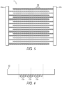
- Fig. 5 shows a plan view of an electrode structure in which the electrodes 12a, 12b are provided with sharp or pointed edges 19
- Fig. 6 shows a cross-sectional side elevation in which the electrodes 12a, 12b are mounted to an electrode support 13 and have a square cross-section.
- the cross section of the electrodes 12a,12b is shown.
- the electrodes 12a, 12b can take the form of long rods having a length axis that protrudes perpendicular to the plane of the drawing.
- the electrodes 12a, 12b can also take the form shown in Fig. 5 .
- the electrodes 12a, 12b can be moved across the skin but not rotated, in which case an intermittent electrode array having electrodes 12a,12b in different orientations, such as that shown in Fig. 3 , can expose the bacteria on the skin to different electrical field orientations.
- the dot-like electrodes 12a, 12b of Fig. 5 can be electrically controlled individually using driver electronics to create a rotating electrical field without moving or rotating the electrode structures. Furthermore, by applying different voltages on the individual electrodes 12a, 12b over time the resulting electrical field can be rotated thereby increasing the efficacy of inactivation for those bacteria with a non spherical aspect ratio.
- the electrical drivers can be based on active matrix technology as substrate. Such an arrangement is a cheap way to generate array of individually addressable electrodes (to e.g. rotate field); compatible with curved or flexible substrates.
- a voltage profile over time can be chosen such that an effective electroporation generates an acceptable temperature increase of the skin. It has been found that for pulses of 50 microseconds up to 100 pulses as function of electrode gap of between 5 and 10 micron, the temperature increase on 5 micron depth into the stratum corneum 15 remains below 45 degrees Celsius.
- a further embodiment is envisaged in which the intermittent electrode array is combined with a hydrodynamic probe which will feed demineralised or tap water of low conductivity to the skin, thereby diluting sweat in order to lower the salt concentration of the liquid on the skin. This will reduce any heating effect.
- the probe will be capable of aspirating liquid as well as delivering it to the skin to ensure that no dripping occurs. If the device incorporates a hydrodynamic probe, it will also have a refillable reservoir for storing liquid and a pump or pumps capable of dispensing the liquid onto the skin and aspirating the liquid from the skin.
- the hydrodynamic probe may contain additional substances that counteract irritation and will work in a smoothing manner on the skin and may also be able to direct a jet of dry, possibly heated, air in order to dry the armpit before exposing it to an electrical field.
- the hydrodynamic probe could also be used to dispense particular chemicals, such as a salt solution, with similar ion content as sweat or a solution representing a mild acid such as Citric acid in low concentration. This can have the result of reducing the required electrical field strength by about a factor of two, while maintaining the same bacterial inactivation efficacy.
- the device of the invention will rely primarily on the principle of electroporation in order to inactivate bacterial cells, it is possible to integrate other inactivation technologies that can be used simultaneously or consecutively with electroporation.
- the device may rely on electroporation in conjunction with light or cold plasma bacterial inactivation techniques.
- the device can incorporate a switch so that when the device is pushed against the skin the electrodes are activated automatically.
- the hydrodynamic probe can also be operated automatically in this way.
- the probe may be configured to dispense and simultaneously aspirate fluid for a short period of time prior to automatic activation of the electrodes.
Landscapes
- Health & Medical Sciences (AREA)
- Life Sciences & Earth Sciences (AREA)
- Engineering & Computer Science (AREA)
- General Health & Medical Sciences (AREA)
- Veterinary Medicine (AREA)
- Animal Behavior & Ethology (AREA)
- Public Health (AREA)
- Biomedical Technology (AREA)
- Radiology & Medical Imaging (AREA)
- Nuclear Medicine, Radiotherapy & Molecular Imaging (AREA)
- Biophysics (AREA)
- Bioinformatics & Cheminformatics (AREA)
- Epidemiology (AREA)
- Chemical & Material Sciences (AREA)
- Molecular Biology (AREA)
- Medicinal Chemistry (AREA)
- Genetics & Genomics (AREA)
- Wood Science & Technology (AREA)
- Zoology (AREA)
- Organic Chemistry (AREA)
- Biotechnology (AREA)
- Microbiology (AREA)
- Biochemistry (AREA)
- General Engineering & Computer Science (AREA)
- Electrotherapy Devices (AREA)
- Apparatus For Disinfection Or Sterilisation (AREA)
Applications Claiming Priority (2)
| Application Number | Priority Date | Filing Date | Title |
|---|---|---|---|
| EP14166869 | 2014-05-02 | ||
| PCT/EP2015/059373 WO2015165986A1 (en) | 2014-05-02 | 2015-04-29 | A device for inactivating bacteria |
Publications (2)
| Publication Number | Publication Date |
|---|---|
| EP3137160A1 EP3137160A1 (en) | 2017-03-08 |
| EP3137160B1 true EP3137160B1 (en) | 2023-04-19 |
Family
ID=50679877
Family Applications (1)
| Application Number | Title | Priority Date | Filing Date |
|---|---|---|---|
| EP15720065.0A Active EP3137160B1 (en) | 2014-05-02 | 2015-04-29 | A device for inactivating bacteria |
Country Status (6)
| Country | Link |
|---|---|
| US (1) | US10384051B2 (enExample) |
| EP (1) | EP3137160B1 (enExample) |
| JP (1) | JP6751351B2 (enExample) |
| CN (1) | CN106255525B (enExample) |
| RU (1) | RU2699278C2 (enExample) |
| WO (1) | WO2015165986A1 (enExample) |
Families Citing this family (9)
| Publication number | Priority date | Publication date | Assignee | Title |
|---|---|---|---|---|
| US20180099140A1 (en) * | 2012-06-18 | 2018-04-12 | Michael Tavger | Method and system for triggering wound recovery by delivering solution into the pores of recipient |
| MX375691B (es) * | 2016-03-22 | 2025-03-06 | Koninklijke Philips Nv | Dispositivo de plasma frio para tratar la piel. |
| KR102497377B1 (ko) | 2017-03-27 | 2023-02-08 | 노보셀 리미티드 | 피내 용액 전달을 위한 시스템, 장치, 및 방법 |
| JP6708317B2 (ja) | 2018-03-05 | 2020-06-10 | 株式会社村田製作所 | 抗菌デバイス、及び電気機器 |
| KR102132370B1 (ko) * | 2018-03-13 | 2020-08-05 | 주식회사 지씨에스 | 피부관리장치, 피부관리장치의 구동방법 및 컴퓨터 판독가능 기록매체 |
| US12285206B2 (en) * | 2020-06-01 | 2025-04-29 | Biosense Webster (Israel) Ltd. | Application of irreversible electroporation (IRE) ablation using catheter with electrode array |
| CA3183538A1 (en) * | 2020-07-02 | 2022-01-06 | Mary K. CANTY | Method for optimizing treatment of infected metallic implants by measuring charge transfer |
| CN115350400A (zh) * | 2022-09-06 | 2022-11-18 | 北京翌光科技有限公司 | 一种射频美容装置 |
| TWI847384B (zh) * | 2022-11-23 | 2024-07-01 | 國立清華大學 | 熱電驅動穿戴系統 |
Citations (1)
| Publication number | Priority date | Publication date | Assignee | Title |
|---|---|---|---|---|
| US20020010414A1 (en) * | 1999-08-25 | 2002-01-24 | Coston Anthony F. | Tissue electroperforation for enhanced drug delivery and diagnostic sampling |
Family Cites Families (18)
| Publication number | Priority date | Publication date | Assignee | Title |
|---|---|---|---|---|
| WO1989006555A1 (en) * | 1988-01-21 | 1989-07-27 | Massachusetts Institute Of Technology | Transport of molecules across tissue using electroporation |
| US5439440A (en) * | 1993-04-01 | 1995-08-08 | Genetronics, Inc. | Electroporation system with voltage control feedback for clinical applications |
| US5702359A (en) | 1995-06-06 | 1997-12-30 | Genetronics, Inc. | Needle electrodes for mediated delivery of drugs and genes |
| US5983131A (en) * | 1995-08-11 | 1999-11-09 | Massachusetts Institute Of Technology | Apparatus and method for electroporation of tissue |
| TW368420B (en) * | 1997-11-04 | 1999-09-01 | Genetronics Inc | Apparatus and method for transdermal molecular delivery by applying sufficient amplitude of electric field to induce migration of molecules through pores in the stratum corneum |
| JP2002520101A (ja) * | 1998-07-13 | 2002-07-09 | ジェネトロニクス、インコーポレーテッド | 電気的に補助される化粧用薬剤の局部送達法および装置 |
| US6148232A (en) * | 1998-11-09 | 2000-11-14 | Elecsys Ltd. | Transdermal drug delivery and analyte extraction |
| US6708060B1 (en) * | 1998-11-09 | 2004-03-16 | Transpharma Ltd. | Handheld apparatus and method for transdermal drug delivery and analyte extraction |
| CN1606461B (zh) | 2001-10-24 | 2011-03-23 | 纸型电池有限公司 | 一种用制剂作皮肤治疗的装置、一种成套器具及皮肤贴片 |
| US8734421B2 (en) | 2003-06-30 | 2014-05-27 | Johnson & Johnson Consumer Companies, Inc. | Methods of treating pores on the skin with electricity |
| EP1682217A4 (en) * | 2003-11-13 | 2008-04-30 | Alza Corp | SYSTEM UDN PROCEDURE FOR THE TRANSDERMAL LEVY |
| US20080063866A1 (en) * | 2006-05-26 | 2008-03-13 | Georgia Tech Research Corporation | Method for Making Electrically Conductive Three-Dimensional Structures |
| US20090048651A1 (en) | 2007-08-17 | 2009-02-19 | Biofisica Inc. | Medical electrode systems and methods |
| EP2156860A1 (en) * | 2008-08-20 | 2010-02-24 | Centre National De La Recherche Scientifique-CNRS | Method for producing insulated electrodes for applying electric fields into conductive material |
| US9895189B2 (en) * | 2009-06-19 | 2018-02-20 | Angiodynamics, Inc. | Methods of sterilization and treating infection using irreversible electroporation |
| WO2012082688A1 (en) * | 2010-12-15 | 2012-06-21 | Old Dominion University Research Foundation | Electroporation-induced electrosensitization |
| RU2477155C2 (ru) * | 2011-04-27 | 2013-03-10 | Закрытое акционерное общество "Патент-Фарм" | Способ лечения андрогенетической алопеции |
| EP3473296B1 (en) * | 2011-06-28 | 2020-08-05 | Inovio Pharmaceuticals, Inc. | A minimally invasive dermal electroporation device |
-
2015
- 2015-04-29 US US15/306,850 patent/US10384051B2/en active Active
- 2015-04-29 EP EP15720065.0A patent/EP3137160B1/en active Active
- 2015-04-29 WO PCT/EP2015/059373 patent/WO2015165986A1/en not_active Ceased
- 2015-04-29 JP JP2016565352A patent/JP6751351B2/ja active Active
- 2015-04-29 CN CN201580021888.XA patent/CN106255525B/zh active Active
- 2015-04-29 RU RU2016147150A patent/RU2699278C2/ru active
Patent Citations (1)
| Publication number | Priority date | Publication date | Assignee | Title |
|---|---|---|---|---|
| US20020010414A1 (en) * | 1999-08-25 | 2002-01-24 | Coston Anthony F. | Tissue electroperforation for enhanced drug delivery and diagnostic sampling |
Also Published As
| Publication number | Publication date |
|---|---|
| CN106255525A (zh) | 2016-12-21 |
| US20170043154A1 (en) | 2017-02-16 |
| CN106255525B (zh) | 2020-02-11 |
| RU2016147150A3 (enExample) | 2018-12-07 |
| US10384051B2 (en) | 2019-08-20 |
| JP2017520285A (ja) | 2017-07-27 |
| EP3137160A1 (en) | 2017-03-08 |
| JP6751351B2 (ja) | 2020-09-02 |
| RU2699278C2 (ru) | 2019-09-04 |
| RU2016147150A (ru) | 2018-06-05 |
| WO2015165986A1 (en) | 2015-11-05 |
Similar Documents
| Publication | Publication Date | Title |
|---|---|---|
| EP3137160B1 (en) | A device for inactivating bacteria | |
| US11260165B2 (en) | Methods, systems, and apparatuses for delivery of electrolysis products | |
| EP1448263B1 (en) | Device for controlled delivery of active substance into the skin | |
| US6757560B1 (en) | Transdermal delivery system (TDS) with electrode network | |
| AU2002347567B2 (en) | Dermal patch | |
| JP5894678B2 (ja) | 患者の経胸的インピーダンスを減少させる器具及び方法 | |
| US8343147B2 (en) | Electrolytic tissue treatment | |
| KR101970644B1 (ko) | 경피 전달 촉진을 위한 복합 시술 장치 | |
| JP2017520285A5 (enExample) | ||
| WO2005068016A1 (en) | Dermal patch for iontophoresis | |
| AU2018364435B2 (en) | Apparatus and methods for the transdermal delivery of active agents | |
| US20110071491A1 (en) | Current Concentration System and Method for Electrokinetic Delivery of Medicaments | |
| ES2800901T3 (es) | Dispositivo de iontoforesis con pieza de extremo multi-electrodo | |
| KR20200116569A (ko) | 경피 전달 촉진을 위한 복합 시술 장치 | |
| AU2006238425A1 (en) | DC tissue treatment | |
| KR101200249B1 (ko) | 경피 약물 전달 장치 |
Legal Events
| Date | Code | Title | Description |
|---|---|---|---|
| STAA | Information on the status of an ep patent application or granted ep patent |
Free format text: STATUS: THE INTERNATIONAL PUBLICATION HAS BEEN MADE |
|
| PUAI | Public reference made under article 153(3) epc to a published international application that has entered the european phase |
Free format text: ORIGINAL CODE: 0009012 |
|
| STAA | Information on the status of an ep patent application or granted ep patent |
Free format text: STATUS: REQUEST FOR EXAMINATION WAS MADE |
|
| 17P | Request for examination filed |
Effective date: 20161202 |
|
| AK | Designated contracting states |
Kind code of ref document: A1 Designated state(s): AL AT BE BG CH CY CZ DE DK EE ES FI FR GB GR HR HU IE IS IT LI LT LU LV MC MK MT NL NO PL PT RO RS SE SI SK SM TR |
|
| AX | Request for extension of the european patent |
Extension state: BA ME |
|
| DAV | Request for validation of the european patent (deleted) | ||
| DAX | Request for extension of the european patent (deleted) | ||
| RAP1 | Party data changed (applicant data changed or rights of an application transferred) |
Owner name: KONINKLIJKE PHILIPS N.V. |
|
| STAA | Information on the status of an ep patent application or granted ep patent |
Free format text: STATUS: EXAMINATION IS IN PROGRESS |
|
| 17Q | First examination report despatched |
Effective date: 20200422 |
|
| GRAP | Despatch of communication of intention to grant a patent |
Free format text: ORIGINAL CODE: EPIDOSNIGR1 |
|
| STAA | Information on the status of an ep patent application or granted ep patent |
Free format text: STATUS: GRANT OF PATENT IS INTENDED |
|
| RIC1 | Information provided on ipc code assigned before grant |
Ipc: A61L 2/03 20060101ALI20221019BHEP Ipc: A61L 2/00 20060101ALI20221019BHEP Ipc: A61N 1/32 20060101ALI20221019BHEP Ipc: A61N 1/04 20060101ALI20221019BHEP Ipc: A61B 18/00 20060101ALI20221019BHEP Ipc: A61N 1/30 20060101AFI20221019BHEP |
|
| INTG | Intention to grant announced |
Effective date: 20221114 |
|
| GRAS | Grant fee paid |
Free format text: ORIGINAL CODE: EPIDOSNIGR3 |
|
| GRAA | (expected) grant |
Free format text: ORIGINAL CODE: 0009210 |
|
| STAA | Information on the status of an ep patent application or granted ep patent |
Free format text: STATUS: THE PATENT HAS BEEN GRANTED |
|
| AK | Designated contracting states |
Kind code of ref document: B1 Designated state(s): AL AT BE BG CH CY CZ DE DK EE ES FI FR GB GR HR HU IE IS IT LI LT LU LV MC MK MT NL NO PL PT RO RS SE SI SK SM TR |
|
| REG | Reference to a national code |
Ref country code: GB Ref legal event code: FG4D |
|
| REG | Reference to a national code |
Ref country code: DE Ref legal event code: R096 Ref document number: 602015083216 Country of ref document: DE |
|
| REG | Reference to a national code |
Ref country code: CH Ref legal event code: EP |
|
| REG | Reference to a national code |
Ref country code: IE Ref legal event code: FG4D |
|
| REG | Reference to a national code |
Ref country code: AT Ref legal event code: REF Ref document number: 1560755 Country of ref document: AT Kind code of ref document: T Effective date: 20230515 |
|
| REG | Reference to a national code |
Ref country code: LT Ref legal event code: MG9D |
|
| REG | Reference to a national code |
Ref country code: NL Ref legal event code: MP Effective date: 20230419 |
|
| REG | Reference to a national code |
Ref country code: AT Ref legal event code: MK05 Ref document number: 1560755 Country of ref document: AT Kind code of ref document: T Effective date: 20230419 |
|
| PG25 | Lapsed in a contracting state [announced via postgrant information from national office to epo] |
Ref country code: NL Free format text: LAPSE BECAUSE OF FAILURE TO SUBMIT A TRANSLATION OF THE DESCRIPTION OR TO PAY THE FEE WITHIN THE PRESCRIBED TIME-LIMIT Effective date: 20230419 |
|
| PG25 | Lapsed in a contracting state [announced via postgrant information from national office to epo] |
Ref country code: SE Free format text: LAPSE BECAUSE OF FAILURE TO SUBMIT A TRANSLATION OF THE DESCRIPTION OR TO PAY THE FEE WITHIN THE PRESCRIBED TIME-LIMIT Effective date: 20230419 Ref country code: PT Free format text: LAPSE BECAUSE OF FAILURE TO SUBMIT A TRANSLATION OF THE DESCRIPTION OR TO PAY THE FEE WITHIN THE PRESCRIBED TIME-LIMIT Effective date: 20230821 Ref country code: NO Free format text: LAPSE BECAUSE OF FAILURE TO SUBMIT A TRANSLATION OF THE DESCRIPTION OR TO PAY THE FEE WITHIN THE PRESCRIBED TIME-LIMIT Effective date: 20230719 Ref country code: ES Free format text: LAPSE BECAUSE OF FAILURE TO SUBMIT A TRANSLATION OF THE DESCRIPTION OR TO PAY THE FEE WITHIN THE PRESCRIBED TIME-LIMIT Effective date: 20230419 Ref country code: AT Free format text: LAPSE BECAUSE OF FAILURE TO SUBMIT A TRANSLATION OF THE DESCRIPTION OR TO PAY THE FEE WITHIN THE PRESCRIBED TIME-LIMIT Effective date: 20230419 |
|
| PG25 | Lapsed in a contracting state [announced via postgrant information from national office to epo] |
Ref country code: RS Free format text: LAPSE BECAUSE OF FAILURE TO SUBMIT A TRANSLATION OF THE DESCRIPTION OR TO PAY THE FEE WITHIN THE PRESCRIBED TIME-LIMIT Effective date: 20230419 Ref country code: PL Free format text: LAPSE BECAUSE OF FAILURE TO SUBMIT A TRANSLATION OF THE DESCRIPTION OR TO PAY THE FEE WITHIN THE PRESCRIBED TIME-LIMIT Effective date: 20230419 Ref country code: LV Free format text: LAPSE BECAUSE OF FAILURE TO SUBMIT A TRANSLATION OF THE DESCRIPTION OR TO PAY THE FEE WITHIN THE PRESCRIBED TIME-LIMIT Effective date: 20230419 Ref country code: LT Free format text: LAPSE BECAUSE OF FAILURE TO SUBMIT A TRANSLATION OF THE DESCRIPTION OR TO PAY THE FEE WITHIN THE PRESCRIBED TIME-LIMIT Effective date: 20230419 Ref country code: IS Free format text: LAPSE BECAUSE OF FAILURE TO SUBMIT A TRANSLATION OF THE DESCRIPTION OR TO PAY THE FEE WITHIN THE PRESCRIBED TIME-LIMIT Effective date: 20230819 Ref country code: HR Free format text: LAPSE BECAUSE OF FAILURE TO SUBMIT A TRANSLATION OF THE DESCRIPTION OR TO PAY THE FEE WITHIN THE PRESCRIBED TIME-LIMIT Effective date: 20230419 Ref country code: GR Free format text: LAPSE BECAUSE OF FAILURE TO SUBMIT A TRANSLATION OF THE DESCRIPTION OR TO PAY THE FEE WITHIN THE PRESCRIBED TIME-LIMIT Effective date: 20230720 Ref country code: AL Free format text: LAPSE BECAUSE OF FAILURE TO SUBMIT A TRANSLATION OF THE DESCRIPTION OR TO PAY THE FEE WITHIN THE PRESCRIBED TIME-LIMIT Effective date: 20230419 |
|
| REG | Reference to a national code |
Ref country code: CH Ref legal event code: PL |
|
| PG25 | Lapsed in a contracting state [announced via postgrant information from national office to epo] |
Ref country code: LU Free format text: LAPSE BECAUSE OF NON-PAYMENT OF DUE FEES Effective date: 20230429 Ref country code: FI Free format text: LAPSE BECAUSE OF FAILURE TO SUBMIT A TRANSLATION OF THE DESCRIPTION OR TO PAY THE FEE WITHIN THE PRESCRIBED TIME-LIMIT Effective date: 20230419 |
|
| REG | Reference to a national code |
Ref country code: BE Ref legal event code: MM Effective date: 20230430 |
|
| PG25 | Lapsed in a contracting state [announced via postgrant information from national office to epo] |
Ref country code: SK Free format text: LAPSE BECAUSE OF FAILURE TO SUBMIT A TRANSLATION OF THE DESCRIPTION OR TO PAY THE FEE WITHIN THE PRESCRIBED TIME-LIMIT Effective date: 20230419 |
|
| PG25 | Lapsed in a contracting state [announced via postgrant information from national office to epo] |
Ref country code: MC Free format text: LAPSE BECAUSE OF FAILURE TO SUBMIT A TRANSLATION OF THE DESCRIPTION OR TO PAY THE FEE WITHIN THE PRESCRIBED TIME-LIMIT Effective date: 20230419 |
|
| REG | Reference to a national code |
Ref country code: DE Ref legal event code: R097 Ref document number: 602015083216 Country of ref document: DE |
|
| PG25 | Lapsed in a contracting state [announced via postgrant information from national office to epo] |
Ref country code: SM Free format text: LAPSE BECAUSE OF FAILURE TO SUBMIT A TRANSLATION OF THE DESCRIPTION OR TO PAY THE FEE WITHIN THE PRESCRIBED TIME-LIMIT Effective date: 20230419 Ref country code: SK Free format text: LAPSE BECAUSE OF FAILURE TO SUBMIT A TRANSLATION OF THE DESCRIPTION OR TO PAY THE FEE WITHIN THE PRESCRIBED TIME-LIMIT Effective date: 20230419 Ref country code: RO Free format text: LAPSE BECAUSE OF FAILURE TO SUBMIT A TRANSLATION OF THE DESCRIPTION OR TO PAY THE FEE WITHIN THE PRESCRIBED TIME-LIMIT Effective date: 20230419 Ref country code: MC Free format text: LAPSE BECAUSE OF FAILURE TO SUBMIT A TRANSLATION OF THE DESCRIPTION OR TO PAY THE FEE WITHIN THE PRESCRIBED TIME-LIMIT Effective date: 20230419 Ref country code: LI Free format text: LAPSE BECAUSE OF NON-PAYMENT OF DUE FEES Effective date: 20230430 Ref country code: EE Free format text: LAPSE BECAUSE OF FAILURE TO SUBMIT A TRANSLATION OF THE DESCRIPTION OR TO PAY THE FEE WITHIN THE PRESCRIBED TIME-LIMIT Effective date: 20230419 Ref country code: DK Free format text: LAPSE BECAUSE OF FAILURE TO SUBMIT A TRANSLATION OF THE DESCRIPTION OR TO PAY THE FEE WITHIN THE PRESCRIBED TIME-LIMIT Effective date: 20230419 Ref country code: CZ Free format text: LAPSE BECAUSE OF FAILURE TO SUBMIT A TRANSLATION OF THE DESCRIPTION OR TO PAY THE FEE WITHIN THE PRESCRIBED TIME-LIMIT Effective date: 20230419 Ref country code: CH Free format text: LAPSE BECAUSE OF NON-PAYMENT OF DUE FEES Effective date: 20230430 |
|
| REG | Reference to a national code |
Ref country code: IE Ref legal event code: MM4A |
|
| PLBE | No opposition filed within time limit |
Free format text: ORIGINAL CODE: 0009261 |
|
| STAA | Information on the status of an ep patent application or granted ep patent |
Free format text: STATUS: NO OPPOSITION FILED WITHIN TIME LIMIT |
|
| PG25 | Lapsed in a contracting state [announced via postgrant information from national office to epo] |
Ref country code: BE Free format text: LAPSE BECAUSE OF NON-PAYMENT OF DUE FEES Effective date: 20230430 |
|
| 26N | No opposition filed |
Effective date: 20240122 |
|
| PG25 | Lapsed in a contracting state [announced via postgrant information from national office to epo] |
Ref country code: IE Free format text: LAPSE BECAUSE OF NON-PAYMENT OF DUE FEES Effective date: 20230429 |
|
| PG25 | Lapsed in a contracting state [announced via postgrant information from national office to epo] |
Ref country code: IE Free format text: LAPSE BECAUSE OF NON-PAYMENT OF DUE FEES Effective date: 20230429 |
|
| PG25 | Lapsed in a contracting state [announced via postgrant information from national office to epo] |
Ref country code: SI Free format text: LAPSE BECAUSE OF FAILURE TO SUBMIT A TRANSLATION OF THE DESCRIPTION OR TO PAY THE FEE WITHIN THE PRESCRIBED TIME-LIMIT Effective date: 20230419 |
|
| PG25 | Lapsed in a contracting state [announced via postgrant information from national office to epo] |
Ref country code: SI Free format text: LAPSE BECAUSE OF FAILURE TO SUBMIT A TRANSLATION OF THE DESCRIPTION OR TO PAY THE FEE WITHIN THE PRESCRIBED TIME-LIMIT Effective date: 20230419 Ref country code: IT Free format text: LAPSE BECAUSE OF FAILURE TO SUBMIT A TRANSLATION OF THE DESCRIPTION OR TO PAY THE FEE WITHIN THE PRESCRIBED TIME-LIMIT Effective date: 20230419 |
|
| PGFP | Annual fee paid to national office [announced via postgrant information from national office to epo] |
Ref country code: GB Payment date: 20240423 Year of fee payment: 10 |
|
| PGFP | Annual fee paid to national office [announced via postgrant information from national office to epo] |
Ref country code: DE Payment date: 20240429 Year of fee payment: 10 |
|
| PGFP | Annual fee paid to national office [announced via postgrant information from national office to epo] |
Ref country code: FR Payment date: 20240430 Year of fee payment: 10 |
|
| PG25 | Lapsed in a contracting state [announced via postgrant information from national office to epo] |
Ref country code: BG Free format text: LAPSE BECAUSE OF FAILURE TO SUBMIT A TRANSLATION OF THE DESCRIPTION OR TO PAY THE FEE WITHIN THE PRESCRIBED TIME-LIMIT Effective date: 20230419 |
|
| PG25 | Lapsed in a contracting state [announced via postgrant information from national office to epo] |
Ref country code: BG Free format text: LAPSE BECAUSE OF FAILURE TO SUBMIT A TRANSLATION OF THE DESCRIPTION OR TO PAY THE FEE WITHIN THE PRESCRIBED TIME-LIMIT Effective date: 20230419 |
|
| PG25 | Lapsed in a contracting state [announced via postgrant information from national office to epo] |
Ref country code: CY Free format text: LAPSE BECAUSE OF FAILURE TO SUBMIT A TRANSLATION OF THE DESCRIPTION OR TO PAY THE FEE WITHIN THE PRESCRIBED TIME-LIMIT; INVALID AB INITIO Effective date: 20150429 |
|
| PG25 | Lapsed in a contracting state [announced via postgrant information from national office to epo] |
Ref country code: HU Free format text: LAPSE BECAUSE OF FAILURE TO SUBMIT A TRANSLATION OF THE DESCRIPTION OR TO PAY THE FEE WITHIN THE PRESCRIBED TIME-LIMIT; INVALID AB INITIO Effective date: 20150429 |