EP3136935B1 - Suction nozzle for removing hair from a textile surface - Google Patents
Suction nozzle for removing hair from a textile surface Download PDFInfo
- Publication number
- EP3136935B1 EP3136935B1 EP15720906.5A EP15720906A EP3136935B1 EP 3136935 B1 EP3136935 B1 EP 3136935B1 EP 15720906 A EP15720906 A EP 15720906A EP 3136935 B1 EP3136935 B1 EP 3136935B1
- Authority
- EP
- European Patent Office
- Prior art keywords
- projections
- suction nozzle
- passage
- width
- face
- Prior art date
- Legal status (The legal status is an assumption and is not a legal conclusion. Google has not performed a legal analysis and makes no representation as to the accuracy of the status listed.)
- Active
Links
Images


Classifications
-
- A—HUMAN NECESSITIES
- A47—FURNITURE; DOMESTIC ARTICLES OR APPLIANCES; COFFEE MILLS; SPICE MILLS; SUCTION CLEANERS IN GENERAL
- A47L—DOMESTIC WASHING OR CLEANING; SUCTION CLEANERS IN GENERAL
- A47L9/00—Details or accessories of suction cleaners, e.g. mechanical means for controlling the suction or for effecting pulsating action; Storing devices specially adapted to suction cleaners or parts thereof; Carrying-vehicles specially adapted for suction cleaners
- A47L9/02—Nozzles
- A47L9/06—Nozzles with fixed, e.g. adjustably fixed brushes or the like
- A47L9/0606—Nozzles with fixed, e.g. adjustably fixed brushes or the like rigidly anchored brushes, combs, lips or pads
- A47L9/0613—Nozzles with fixed, e.g. adjustably fixed brushes or the like rigidly anchored brushes, combs, lips or pads with means specially adapted for picking up threads, hair or the like, e.g. brushes, combs, lint pickers or bristles pads
Definitions
- the present invention relates to a suction nozzle for cleaning apparatuses. More specifically, the present invention relates to a suction nozzle for removing hair from a textile surface.
- Vacuum cleaners are commonly used, but adherence between the animal hairs and the carpeting is such that the vacuum cleaner has to be taken over the same area, time and time again, to effect any sort of thorough removal of the animal hairs.
- a suction nozzle attached to the vacuum cleaner is frequently useful, but the filaments/protrusions of the suction nozzle have to be cleaned out regularly, and this is a messy, difficult, and time consuming chore.
- a suction nozzle for cleaning apparatus is already known e.g. from DE-A-19829044 .
- one object of the present invention is to provide a cleaning tool that both quickly and thoroughly removes animal hairs from textile materials, such as carpet materials.
- One aspect relates to a suction nozzle for cleaning apparatuses, such as vacuum cleaners, for removing hair from a textile surface, comprising:
- the suction nozzle for cleaning apparatuses, such as vacuum cleaners, for removing hair from a textile surface.
- the suction nozzle comprises a housing and a base section.
- textile refers to any material made through weaving, knitting, spreading, crocheting, or bonding that may be used in production of further goods.
- the housing comprises a pipe socket for connecting a pipe of a cleaning apparatus with the suction nozzle.
- the base section has an outer edge, a first face attached to the housing, and a second face comprising a plurality of projections and one or more inlets for airflow.
- the plurality of projections are resilient bendable, i.e. when the projections are bent during a sweeping motion over a textile surface, they rebound (or return) towards their initial position when they lose contact with said textile surface.
- the plurality of projections are made of a material having a Shore A-scale hardness measured according to ASTM D2240-97 within the range of 40-70, such as within the range of 45-70, e.g. within the range of 50-70.
- the projections are made of a material having a Shore A-scale hardness measured according to ASTM D2240-97 within the range of 60-70, e.g. 65-70. This range of hardness secures that the projections are not too soft to withstand continuous and prolonged use, and that they are still resilient bendable. If the hardness is above 70, the projections may risk damaging the textile surface, and lack the resilient bendability.
- projections refers to bristles, filaments or strips or teeth of a flexible material.
- the plurality of projections are so mounted on the second face that when they are brought into contact with the textile surface to be cleaned during a sweeping motion, they are bent away from their initial position, away from the direction of sweep.
- the inventor has found that when using projections where at least the outer layer or coating is made from elastomer, the hairs on a textile surface are rolled together to form elongated hair rolls. Hence, at least the outer layer or coating of the plurality of projections is made from elastomer for accumulating hair on the surface.
- the projections are made from elastomer.
- the term "elastomer” is intended to mean an amorphous high polymer (or mixture thereof) above its/their glass transition temperature. Elastomers can be stretched and retracted rapidly; exhibit high strength and modulus when stretched; and recover fully when the stress is removed.
- the term “elastomer” includes covalently-linked elastomers, in which the polymer(s) is/are permanently cross-linked to restrain gross mobility, and thermoplastic elastomers, in which the polymer(s) is/are reversibly cross-linked to restrain gross mobility.
- Thermoplastic elastomers (TPE) are a class of copolymers or a physical mix of polymers (usually a plastic and a rubber) which consist of materials with both thermoplastic and elastomeric properties.
- the elastomer is selected from the group consisting of polyisobutylene (PIB), butyl rubber (IIR), neoprene (CR), nitrile rubber (NBR), ethylene propylene diene monomer (EPDM), ethylene propylene monomer (EPM), styrene-butadiene-styrene (SBS), polyether block amide (PEBA), thermoplastic polyurethanes (TPU), thermoplastics olefins (TPO), silicone elastomers, vinyl methyl silicone (VMQ), phenyl vinyl methyl silicone (PVMQ), fluoro vinyl methyl silicone (FVMQ), methyl silicone (MQ), fluoroelastomers (FKM), perfluoroelastomers (FFKM), polyacrylic elastomers (ACM), acrylic ethylene (AEM), chlorosulfonated polyethylene (CSM), epichlorohydrin elastomers (CO and ECO
- the plurality of projections are aligned in a plurality of parallel rows, being mounted on the second face of the base section so as to define a passage running from the outer edge towards the one or more inlets for airflow.
- the passage has a distal end facing the outer edge and a proximal end facing the one or more inlets.
- the plurality of parallel rows are mounted in one or more units, wherein a first and a second parallel row in a first unit are offset such that an individual projection in the first row cover the space between two individual (neighbouring) projections in the second row when they are brought into contact with the textile surface to be cleaned during a sweeping motion, and bent away from their initial position, away from the direction of sweep.
- Such construction has proven to be especially effective at releasing the hairs from the textile surface.
- the plurality of projections are so mounted on the second face that the width of an individual projection is equal to or larger than the space between two individual (neighbouring) projections in the same row.
- the plurality of projections are so mounted on the second face that the width of an individual projection is equal to or larger than the space between two individual neighbouring projections in the same row.
- the projections are of a minimum length and width for them to bend and interact with (or touch) projections of a neighbouring row.
- the width of the plurality of projections is within the range of 2-30 mm, such as within the range of 3-25 mm, e.g. 4-20 mm, such as within the range of 5-20 mm, e.g. 6-15 mm, such as within the range of 7-15 mm, e.g. 8-15 mm, such as within the range of 9-15 mm, e.g. 10-15 mm.
- the width of the plurality of projections is within the range of 2-10 mm, e.g. 4-8 mm.
- the length of the plurality of projections is within the range of 5-50 mm, such as within the range of 6-45 mm, e.g. 7-40 mm, such as within the range of 8-35 mm, e.g. 9-30 mm, such as within the range of 10-25 mm, e.g. 10-20 mm.
- the width of the plurality of projections is within the range of 8-25 mm, e.g. 12-15 mm.
- the width of the plurality of projections is within the range of 2-30 mm, and the length of the plurality of projections is within the range of 5-50 mm.
- the width of the plurality of projections is 4 mm
- the length of the plurality of projections is 13 mm
- the distance between individual projections in the same row is 3 mm.
- the accumulated hair is then guided/forced through the passage towards the one or more inlets to be suctioned into the vacuum cleaner.
- the inventor has found that it is crucial that the width of the distal end of said passage is at least 1 cm to accommodate the formed elongate hair rolls; and the width of the proximal end of said passage should be narrower than the width of the distal end (so as to form a funnel type shape), for guiding the accumulated hair at the surface towards the one or more inlets. Else, the elongate hair rolls will get stuck in the passage.
- the upper limit of the width of the distal end of said passage is only limited by the dimensions, (e.g.
- the width of the distal end of the passage is at least 1 cm, e.g. at least 2 cm, such as at least 3 cm, e.g. at least 4 cm, such as at least 5 cm, e.g. at least 6 cm, such as at least 7 cm, e.g. at least 8 cm, such as at least 9 cm, e.g. at least 10 cm, such as at least 11 cm, e.g. at least 12 cm, such as at least 13 cm, e.g. at least 14 cm, such as at least 15 cm, e.g. at least 20 cm.
- the plurality of parallel rows are mounted in a plurality of units, wherein the plurality of units are mounted on the second face of the base section so as to define a passage running from the outer edge towards the one or more inlets for airflow, said passage having a distal end facing the outer edge and a proximal end facing the one or more inlets; wherein the width of the distal end of said passage is at least 1 cm, and wherein the width of the proximal end of said passage is narrower than the width of the distal end, for guiding the accumulated hair at the surface towards the one or more inlets.
- the width of the distal end of the passage is at least 1 cm, e.g.
- At least 2 cm such as at least 3 cm, e.g. at least 4 cm, such as at least 5 cm, e.g. at least 6 cm, such as at least 7 cm, e.g. at least 8 cm, such as at least 9 cm, e.g. at least 10 cm, such as at least 11 cm, e.g. at least 12 cm, such as at least 13 cm, e.g. at least 14 cm, such as at least 15 cm, e.g. at least 20 cm.
- the passage formed by the plurality of rows and/or the plurality of units runs essentially parallel to the intended direction of sweep.
- At least the central portion of the passage formed by the plurality of rows and/or the plurality of units runs essentially parallel to the intended direction of sweep.
- the width of the plurality of projections have different moments of resistance depending on the bending direction, so that when they are brought into contact with the textile surface to be cleaned, they are bent essentially in the lowest moment of resistance.
- the projections have a high co-efficient of friction with the textile surface.
- the process of electron transfer as a result of two objects coming into contact with each other and then separating is known as 'triboelectric charging'.
- the process of triboelectric charging results in one object gaining electrons on its surface, and therefore becoming negatively charged, and another object losing electrons from its surface, and therefore becoming positively charged.
- Which material becomes negative and which becomes positive depend on the relative tendencies of the materials involved to gain or lose electrons. Some materials have a greater tendency to gain electrons than most others, in the same way that there are others which tend to lose electrons easier than others. Hair has a tendency to become triboelectrically positively chargeable when in contact with a textile surface.
- At least the outer layer, or coating, of the plurality of projections is made from elastomer which is triboelectrically negatively chargeable for releasing the hair from said textile surface.
- a static discharge in the presence of air or oxygen can create ozone.
- Many elastomers are sensitive to ozone cracking. Exposure to ozone may therefore create deep penetrative cracks in the projections unless preventive action is taken.
- the projections are made from an elastomer composition further comprising anti-ozonants.
- the projections are made from ozone-resistant elastomer.
- the plurality of parallel rows are offset such that a first row of the aligned projections is not aligned with a second row of the aligned projections.
- the free end face of an individual projection may be shaped with corners or edges, as for example if the free end face of the projections are v-shaped, star-shaped, squared or triangular; wherein the individual projection has a planar end face.
- At least the free end face of an individual projection has a non-circular shape wherein the individual projection has a planar end face.
- At least the free end face of an individual projection has a shape selected from the group consisting of squared, v-shaped, star-shaped, and triangular; wherein the individual projection has a planar end face.
- the individual projection has a non-circular cross-section taken near its tip.
- the individual projection has a squared, v-shaped, star-shaped, or triangular cross-section taken near its tip.
- the projections have at least a semi-rigid core, coated by elastomer, to provide sufficient rigidity to the projections; wherein the semi-rigid core being made of a material having a Shore A-scale hardness measured according to ASTM D2240-97 within the range of 50-70, such as a Shore A-scale hardness measured according to ASTM D2240-97 within the range of 60-70, e.g. 65-70.
- Vacuum cleaners typically have a suction nozzle in communication with a source of suction.
- the suction nozzle therefore forms an inlet for airflow, where dirt and other debris together with the air are suctioned into the vacuum cleaner.
- Vacuum cleaners may be provided with means for cleaning along edges or baseboards of rooms and near kick plates of cabinetry and appliances. Such means include providing a vacuum hose between the suction nozzle and the suction source that can be selectively removed from communication with the suction nozzle. When the vacuum hose is removed from the suction nozzle, suction is generated at the inlet of the vacuum hose.
- One object of the present invention is to provide a cleaning tool that both quickly and thoroughly removes animal hairs from textile materials, such as carpet materials.
- a suction nozzle 1 for cleaning apparatuses, such as vacuum cleaners, for removing hair from a textile surface comprising:
- a suction nozzle viewed from the second face is shown having only one inlet 6 for airflow.
- This embodiment allows the hair rolls to be directed through one passage at each side of the outer edge 4A towards the one centrally placed inlet 6.
- the planar end faces of the projections are v-shaped.
- the plurality of parallel rows 7 are mounted in four units 10A-D, and a first and a second parallel row 7A, 7B in a first unit 10A are offset such that an individual projection 5C in the first row 7A cover the space between two individual (neighbouring) projections 5A, 5B in the second row 7B when they are brought into contact with the textile surface to be cleaned during a sweeping motion, and bent away from their initial position, away from the direction of sweep.
- the units 10A and 10B are mounted on the second face of the base section so as to define a passage 8 running from the outer (front) edge towards the centrally placed inlet 6 for airflow.
- the passage has a distal end facing the outer (front) edge and a proximal end facing the centrally placed inlet 6.
- the units 10C and 10D are mounted on the second face of the base section so as to define a passage 8 running from the outer (back) edge towards the centrally placed inlet 6 for airflow.
- the passage has a distal end facing the outer (back) edge and a proximal end facing the centrally placed inlet 6.
- the central portion of the passage formed by the plurality of units 10A-B; 10C-D runs essentially parallel to the intended direction of sweep.
- the width of the plurality of projections have different moments of resistance depending on the bending direction, so that when they are brought into contact with the textile surface to be cleaned, they are bent essentially in the lowest moment of resistance.
- the projections of units 10A and 10B are bent backward, while the projections of units 10C and 10D will be more resistant to bending; and when the suction nozzle is moved backward, the projections of units 10C and 10D are bent forward, while the projections of units 10A and 10B will be more resistant to bending bending.
- a suction nozzle viewed from the second face having only one inlet 6 for airflow.
- This embodiment allows the hair rolls to be directed through one passage at only two sides of the outer edge towards the one centrally placed inlet 6.
- the planar end faces of the projections are v-shaped; and a first and a second parallel row in a first unit are offset such that an individual projection in the first row covers the space between two individual (neighbouring) projections in the second row when they are brought into contact with the textile surface to be cleaned during a sweeping motion, and bent away from their initial position, away from the direction of sweep.
- two units are mounted on the second face of the base section so as to define a passage 8 running from the outer (front) edge towards the centrally placed inlet 6 for airflow.
- the passage has a distal end facing the outer (front) edge and a proximal end facing the centrally placed inlet 6.
- two units are mounted on the second face of the base section so as to define a passage 8 running from the outer (back) edge towards the centrally placed inlet 6 for airflow.
- the passage has a distal end facing the outer (back) edge and a proximal end facing the centrally placed inlet 6.
- the projections are mounted in the individual units so that the widths of the plurality of projections have different moments of resistance depending on the bending direction.
- the two units facing the outer (front) edge have projections with the same moments of resistance at a given bending direction; and the two units facing the outer (back) edge have projections with the same moments of resistance at a given bending direction.
- a suction nozzle viewed from the second face having two inlets 6 for airflow.
- This embodiment allows the hair rolls to be directed through two passages at the outer (front) edge and two passages at the outer (back) edge towards the two inlets 6.
- the planar end faces of the projections are v-shaped; and a first and a second parallel row in a first unit are offset such that an individual projection in the first row covers the space between two individual (neighbouring) projections in the second row when they are brought into contact with the textile surface to be cleaned during a sweeping motion, and bent away from their initial position, away from the direction of sweep.
- the central portion of the passage formed by the plurality of units 10A-B; 10C-D; 10E-F; 10G-H runs essentially parallel to the intended direction of sweep.
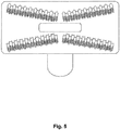
- FIG. 5 a suction nozzle as in Figure 1 is shown. Here, it is shown how the projections from one row in an individual unit are interacting with the projections from a neighbouring row in the same unit, when they are brought into contact with the textile surface to be cleaned during a sweeping motion in the forward direction.
Landscapes
- Engineering & Computer Science (AREA)
- Mechanical Engineering (AREA)
- Nozzles For Electric Vacuum Cleaners (AREA)
Priority Applications (1)
| Application Number | Priority Date | Filing Date | Title |
|---|---|---|---|
| PL15720906T PL3136935T3 (pl) | 2014-05-01 | 2015-04-30 | Dysza ssąca do usuwania sierści z powierzchni tekstylnej |
Applications Claiming Priority (2)
| Application Number | Priority Date | Filing Date | Title |
|---|---|---|---|
| DKPA201470267A DK201470267A1 (en) | 2014-05-01 | 2014-05-01 | Suction nozzle for removing hair from a textile surface |
| PCT/DK2015/050112 WO2015165475A1 (en) | 2014-05-01 | 2015-04-30 | Suction nozzle for removing hair from a textile surface |
Publications (2)
| Publication Number | Publication Date |
|---|---|
| EP3136935A1 EP3136935A1 (en) | 2017-03-08 |
| EP3136935B1 true EP3136935B1 (en) | 2018-11-28 |
Family
ID=53054823
Family Applications (1)
| Application Number | Title | Priority Date | Filing Date |
|---|---|---|---|
| EP15720906.5A Active EP3136935B1 (en) | 2014-05-01 | 2015-04-30 | Suction nozzle for removing hair from a textile surface |
Country Status (6)
| Country | Link |
|---|---|
| US (2) | US10327611B2 (pl) |
| EP (1) | EP3136935B1 (pl) |
| DK (2) | DK201470267A1 (pl) |
| ES (1) | ES2712864T3 (pl) |
| PL (1) | PL3136935T3 (pl) |
| WO (1) | WO2015165475A1 (pl) |
Cited By (1)
| Publication number | Priority date | Publication date | Assignee | Title |
|---|---|---|---|---|
| EP3843600B1 (en) * | 2018-08-31 | 2023-08-16 | Koninklijke Philips N.V. | Vacuum cleaner utensil |
Families Citing this family (2)
| Publication number | Priority date | Publication date | Assignee | Title |
|---|---|---|---|---|
| US11607101B2 (en) * | 2019-08-05 | 2023-03-21 | Bissell Inc. | Vacuum cleaner accessory tool |
| USD1124547S1 (en) | 2023-06-26 | 2026-04-28 | Sharkninja Operating Llc | Surface cleaning device |
Family Cites Families (11)
| Publication number | Priority date | Publication date | Assignee | Title |
|---|---|---|---|---|
| GB315177A (en) * | 1928-11-23 | 1929-07-11 | Vacdus Engineering Company Ltd | Improvements in or relating to vacuum sweeping machines |
| BE542777A (pl) | 1954-11-15 | |||
| FR1331501A (fr) * | 1962-05-23 | 1963-07-05 | Perfectionnements aux suceurs et brosses d'aspirateurs | |
| DE2309137A1 (de) * | 1973-02-23 | 1974-08-29 | Hans Wessel | Staubsaugerduese mit fadenaufnehmern |
| US3955238A (en) * | 1974-09-06 | 1976-05-11 | Corporate Products Research | Dog brush |
| PL131508B2 (en) * | 1983-02-08 | 1984-11-30 | Thread collector for vacuum cleaner suction nozzle or suction nozzle with brush | |
| DE19829044C2 (de) * | 1998-06-29 | 2001-07-12 | Monika Geis | Saugmundstück für Staubsauger |
| AU2006201894B2 (en) | 2005-05-05 | 2010-09-16 | Bissell Inc. | Vacuum accessory tool |
| DE102008021353B4 (de) * | 2008-04-29 | 2017-07-06 | BSH Hausgeräte GmbH | Staubsaugerdüse für einen Staubsauger |
| US8857011B2 (en) * | 2009-01-16 | 2014-10-14 | Robert W. Casper | Pet vacuum cleaner |
| US8677559B2 (en) * | 2011-12-08 | 2014-03-25 | Emerson Electric Co. | Vacuum assisted fur removal tool |
-
2014
- 2014-05-01 DK DKPA201470267A patent/DK201470267A1/en not_active Application Discontinuation
-
2015
- 2015-04-30 WO PCT/DK2015/050112 patent/WO2015165475A1/en not_active Ceased
- 2015-04-30 DK DK15720906.5T patent/DK3136935T3/en active
- 2015-04-30 US US15/307,647 patent/US10327611B2/en active Active
- 2015-04-30 ES ES15720906T patent/ES2712864T3/es active Active
- 2015-04-30 PL PL15720906T patent/PL3136935T3/pl unknown
- 2015-04-30 EP EP15720906.5A patent/EP3136935B1/en active Active
-
2019
- 2019-05-13 US US16/410,838 patent/US11324367B2/en active Active
Non-Patent Citations (1)
| Title |
|---|
| None * |
Cited By (1)
| Publication number | Priority date | Publication date | Assignee | Title |
|---|---|---|---|---|
| EP3843600B1 (en) * | 2018-08-31 | 2023-08-16 | Koninklijke Philips N.V. | Vacuum cleaner utensil |
Also Published As
| Publication number | Publication date |
|---|---|
| US10327611B2 (en) | 2019-06-25 |
| US11324367B2 (en) | 2022-05-10 |
| DK3136935T3 (en) | 2019-03-11 |
| EP3136935A1 (en) | 2017-03-08 |
| WO2015165475A1 (en) | 2015-11-05 |
| PL3136935T3 (pl) | 2019-05-31 |
| ES2712864T3 (es) | 2019-05-16 |
| US20190261823A1 (en) | 2019-08-29 |
| DK201470267A1 (en) | 2015-11-16 |
| US20170049283A1 (en) | 2017-02-23 |
Similar Documents
| Publication | Publication Date | Title |
|---|---|---|
| US11324367B2 (en) | Suction nozzle for removing hair from textile surfaces | |
| US9408518B2 (en) | Retainers for a device having removable floor sheets | |
| US7845047B2 (en) | Cleaning brush | |
| CN109893030B (zh) | 用于抽吸细灰尘和大碎屑的真空吸尘器抽吸头部的底板 | |
| US8677559B2 (en) | Vacuum assisted fur removal tool | |
| CN216704230U (zh) | 用于真空清洁器的搅拌器和具有该搅拌器的表面清洁头 | |
| CN102014721A (zh) | 用于吸尘器的吸尘器喷嘴 | |
| EP3741282A1 (en) | Cleaner equipped with auxiliary cleaning part | |
| CN105979840B (zh) | 用于真空吸尘器的附加工具 | |
| JP2016513513A (ja) | 掃除機ヘッド | |
| JP5560067B2 (ja) | ブラシ及び回転ブラシ | |
| CN102370442B (zh) | 电吸尘器用吸嘴 | |
| JP2016002341A (ja) | ブラシ及び回転ブラシ | |
| CN212438463U (zh) | 用于与表面清洁装置组合使用的衬垫工具的清洁吸嘴 | |
| JP6440965B2 (ja) | 面清掃具 | |
| JP3200339U (ja) | 掃除機ヘッド | |
| JP2023545771A (ja) | 表面処理装置ための撹拌器およびそれを有する表面処理装置 | |
| JP2018134002A (ja) | ブラシ | |
| CN223128714U (zh) | 一种垃圾清理装置 | |
| CN207152214U (zh) | 清洁刷 | |
| JP2021065363A (ja) | 清掃具 | |
| US20120023697A1 (en) | Vacuum attachment assembly | |
| EP3024373B1 (en) | Retainers for a device having removable floor sheets | |
| JP3193923U (ja) | カーペット類に絡みついた毛を除去する清掃用具 | |
| AU2023241141A1 (en) | Cleaning brush |
Legal Events
| Date | Code | Title | Description |
|---|---|---|---|
| STAA | Information on the status of an ep patent application or granted ep patent |
Free format text: STATUS: THE INTERNATIONAL PUBLICATION HAS BEEN MADE |
|
| PUAI | Public reference made under article 153(3) epc to a published international application that has entered the european phase |
Free format text: ORIGINAL CODE: 0009012 |
|
| STAA | Information on the status of an ep patent application or granted ep patent |
Free format text: STATUS: REQUEST FOR EXAMINATION WAS MADE |
|
| 17P | Request for examination filed |
Effective date: 20161110 |
|
| AK | Designated contracting states |
Kind code of ref document: A1 Designated state(s): AL AT BE BG CH CY CZ DE DK EE ES FI FR GB GR HR HU IE IS IT LI LT LU LV MC MK MT NL NO PL PT RO RS SE SI SK SM TR |
|
| AX | Request for extension of the european patent |
Extension state: BA ME |
|
| DAV | Request for validation of the european patent (deleted) | ||
| DAX | Request for extension of the european patent (deleted) | ||
| GRAP | Despatch of communication of intention to grant a patent |
Free format text: ORIGINAL CODE: EPIDOSNIGR1 |
|
| STAA | Information on the status of an ep patent application or granted ep patent |
Free format text: STATUS: GRANT OF PATENT IS INTENDED |
|
| INTG | Intention to grant announced |
Effective date: 20180115 |
|
| GRAJ | Information related to disapproval of communication of intention to grant by the applicant or resumption of examination proceedings by the epo deleted |
Free format text: ORIGINAL CODE: EPIDOSDIGR1 |
|
| STAA | Information on the status of an ep patent application or granted ep patent |
Free format text: STATUS: REQUEST FOR EXAMINATION WAS MADE |
|
| GRAP | Despatch of communication of intention to grant a patent |
Free format text: ORIGINAL CODE: EPIDOSNIGR1 |
|
| STAA | Information on the status of an ep patent application or granted ep patent |
Free format text: STATUS: GRANT OF PATENT IS INTENDED |
|
| INTC | Intention to grant announced (deleted) | ||
| INTG | Intention to grant announced |
Effective date: 20180613 |
|
| GRAS | Grant fee paid |
Free format text: ORIGINAL CODE: EPIDOSNIGR3 |
|
| GRAA | (expected) grant |
Free format text: ORIGINAL CODE: 0009210 |
|
| STAA | Information on the status of an ep patent application or granted ep patent |
Free format text: STATUS: THE PATENT HAS BEEN GRANTED |
|
| AK | Designated contracting states |
Kind code of ref document: B1 Designated state(s): AL AT BE BG CH CY CZ DE DK EE ES FI FR GB GR HR HU IE IS IT LI LT LU LV MC MK MT NL NO PL PT RO RS SE SI SK SM TR |
|
| REG | Reference to a national code |
Ref country code: CH Ref legal event code: EP |
|
| REG | Reference to a national code |
Ref country code: AT Ref legal event code: REF Ref document number: 1069248 Country of ref document: AT Kind code of ref document: T Effective date: 20181215 |
|
| REG | Reference to a national code |
Ref country code: DE Ref legal event code: R096 Ref document number: 602015020383 Country of ref document: DE |
|
| REG | Reference to a national code |
Ref country code: IE Ref legal event code: FG4D |
|
| REG | Reference to a national code |
Ref country code: DK Ref legal event code: T3 Effective date: 20190304 |
|
| REG | Reference to a national code |
Ref country code: SE Ref legal event code: TRGR |
|
| REG | Reference to a national code |
Ref country code: LT Ref legal event code: MG4D Ref country code: NL Ref legal event code: FP |
|
| REG | Reference to a national code |
Ref country code: AT Ref legal event code: MK05 Ref document number: 1069248 Country of ref document: AT Kind code of ref document: T Effective date: 20181128 |
|
| PG25 | Lapsed in a contracting state [announced via postgrant information from national office to epo] |
Ref country code: FI Free format text: LAPSE BECAUSE OF FAILURE TO SUBMIT A TRANSLATION OF THE DESCRIPTION OR TO PAY THE FEE WITHIN THE PRESCRIBED TIME-LIMIT Effective date: 20181128 Ref country code: BG Free format text: LAPSE BECAUSE OF FAILURE TO SUBMIT A TRANSLATION OF THE DESCRIPTION OR TO PAY THE FEE WITHIN THE PRESCRIBED TIME-LIMIT Effective date: 20190228 Ref country code: HR Free format text: LAPSE BECAUSE OF FAILURE TO SUBMIT A TRANSLATION OF THE DESCRIPTION OR TO PAY THE FEE WITHIN THE PRESCRIBED TIME-LIMIT Effective date: 20181128 Ref country code: LV Free format text: LAPSE BECAUSE OF FAILURE TO SUBMIT A TRANSLATION OF THE DESCRIPTION OR TO PAY THE FEE WITHIN THE PRESCRIBED TIME-LIMIT Effective date: 20181128 Ref country code: AT Free format text: LAPSE BECAUSE OF FAILURE TO SUBMIT A TRANSLATION OF THE DESCRIPTION OR TO PAY THE FEE WITHIN THE PRESCRIBED TIME-LIMIT Effective date: 20181128 Ref country code: LT Free format text: LAPSE BECAUSE OF FAILURE TO SUBMIT A TRANSLATION OF THE DESCRIPTION OR TO PAY THE FEE WITHIN THE PRESCRIBED TIME-LIMIT Effective date: 20181128 Ref country code: IS Free format text: LAPSE BECAUSE OF FAILURE TO SUBMIT A TRANSLATION OF THE DESCRIPTION OR TO PAY THE FEE WITHIN THE PRESCRIBED TIME-LIMIT Effective date: 20190328 |
|
| REG | Reference to a national code |
Ref country code: NO Ref legal event code: T2 Effective date: 20181128 |
|
| REG | Reference to a national code |
Ref country code: ES Ref legal event code: FG2A Ref document number: 2712864 Country of ref document: ES Kind code of ref document: T3 Effective date: 20190516 |
|
| PG25 | Lapsed in a contracting state [announced via postgrant information from national office to epo] |
Ref country code: PT Free format text: LAPSE BECAUSE OF FAILURE TO SUBMIT A TRANSLATION OF THE DESCRIPTION OR TO PAY THE FEE WITHIN THE PRESCRIBED TIME-LIMIT Effective date: 20190328 Ref country code: AL Free format text: LAPSE BECAUSE OF FAILURE TO SUBMIT A TRANSLATION OF THE DESCRIPTION OR TO PAY THE FEE WITHIN THE PRESCRIBED TIME-LIMIT Effective date: 20181128 Ref country code: GR Free format text: LAPSE BECAUSE OF FAILURE TO SUBMIT A TRANSLATION OF THE DESCRIPTION OR TO PAY THE FEE WITHIN THE PRESCRIBED TIME-LIMIT Effective date: 20190301 Ref country code: RS Free format text: LAPSE BECAUSE OF FAILURE TO SUBMIT A TRANSLATION OF THE DESCRIPTION OR TO PAY THE FEE WITHIN THE PRESCRIBED TIME-LIMIT Effective date: 20181128 |
|
| PG25 | Lapsed in a contracting state [announced via postgrant information from national office to epo] |
Ref country code: IT Free format text: LAPSE BECAUSE OF FAILURE TO SUBMIT A TRANSLATION OF THE DESCRIPTION OR TO PAY THE FEE WITHIN THE PRESCRIBED TIME-LIMIT Effective date: 20181128 Ref country code: CZ Free format text: LAPSE BECAUSE OF FAILURE TO SUBMIT A TRANSLATION OF THE DESCRIPTION OR TO PAY THE FEE WITHIN THE PRESCRIBED TIME-LIMIT Effective date: 20181128 |
|
| REG | Reference to a national code |
Ref country code: DE Ref legal event code: R097 Ref document number: 602015020383 Country of ref document: DE |
|
| PG25 | Lapsed in a contracting state [announced via postgrant information from national office to epo] |
Ref country code: EE Free format text: LAPSE BECAUSE OF FAILURE TO SUBMIT A TRANSLATION OF THE DESCRIPTION OR TO PAY THE FEE WITHIN THE PRESCRIBED TIME-LIMIT Effective date: 20181128 Ref country code: SM Free format text: LAPSE BECAUSE OF FAILURE TO SUBMIT A TRANSLATION OF THE DESCRIPTION OR TO PAY THE FEE WITHIN THE PRESCRIBED TIME-LIMIT Effective date: 20181128 Ref country code: SK Free format text: LAPSE BECAUSE OF FAILURE TO SUBMIT A TRANSLATION OF THE DESCRIPTION OR TO PAY THE FEE WITHIN THE PRESCRIBED TIME-LIMIT Effective date: 20181128 Ref country code: RO Free format text: LAPSE BECAUSE OF FAILURE TO SUBMIT A TRANSLATION OF THE DESCRIPTION OR TO PAY THE FEE WITHIN THE PRESCRIBED TIME-LIMIT Effective date: 20181128 |
|
| PLBE | No opposition filed within time limit |
Free format text: ORIGINAL CODE: 0009261 |
|
| STAA | Information on the status of an ep patent application or granted ep patent |
Free format text: STATUS: NO OPPOSITION FILED WITHIN TIME LIMIT |
|
| PG25 | Lapsed in a contracting state [announced via postgrant information from national office to epo] |
Ref country code: SI Free format text: LAPSE BECAUSE OF FAILURE TO SUBMIT A TRANSLATION OF THE DESCRIPTION OR TO PAY THE FEE WITHIN THE PRESCRIBED TIME-LIMIT Effective date: 20181128 |
|
| 26N | No opposition filed |
Effective date: 20190829 |
|
| REG | Reference to a national code |
Ref country code: CH Ref legal event code: PL |
|
| PG25 | Lapsed in a contracting state [announced via postgrant information from national office to epo] |
Ref country code: LU Free format text: LAPSE BECAUSE OF NON-PAYMENT OF DUE FEES Effective date: 20190430 Ref country code: MC Free format text: LAPSE BECAUSE OF FAILURE TO SUBMIT A TRANSLATION OF THE DESCRIPTION OR TO PAY THE FEE WITHIN THE PRESCRIBED TIME-LIMIT Effective date: 20181128 |
|
| PG25 | Lapsed in a contracting state [announced via postgrant information from national office to epo] |
Ref country code: CH Free format text: LAPSE BECAUSE OF NON-PAYMENT OF DUE FEES Effective date: 20190430 Ref country code: LI Free format text: LAPSE BECAUSE OF NON-PAYMENT OF DUE FEES Effective date: 20190430 |
|
| PG25 | Lapsed in a contracting state [announced via postgrant information from national office to epo] |
Ref country code: TR Free format text: LAPSE BECAUSE OF FAILURE TO SUBMIT A TRANSLATION OF THE DESCRIPTION OR TO PAY THE FEE WITHIN THE PRESCRIBED TIME-LIMIT Effective date: 20181128 |
|
| PG25 | Lapsed in a contracting state [announced via postgrant information from national office to epo] |
Ref country code: IE Free format text: LAPSE BECAUSE OF NON-PAYMENT OF DUE FEES Effective date: 20190430 |
|
| PG25 | Lapsed in a contracting state [announced via postgrant information from national office to epo] |
Ref country code: CY Free format text: LAPSE BECAUSE OF FAILURE TO SUBMIT A TRANSLATION OF THE DESCRIPTION OR TO PAY THE FEE WITHIN THE PRESCRIBED TIME-LIMIT Effective date: 20181128 |
|
| PG25 | Lapsed in a contracting state [announced via postgrant information from national office to epo] |
Ref country code: MT Free format text: LAPSE BECAUSE OF FAILURE TO SUBMIT A TRANSLATION OF THE DESCRIPTION OR TO PAY THE FEE WITHIN THE PRESCRIBED TIME-LIMIT Effective date: 20181128 Ref country code: HU Free format text: LAPSE BECAUSE OF FAILURE TO SUBMIT A TRANSLATION OF THE DESCRIPTION OR TO PAY THE FEE WITHIN THE PRESCRIBED TIME-LIMIT; INVALID AB INITIO Effective date: 20150430 |
|
| PG25 | Lapsed in a contracting state [announced via postgrant information from national office to epo] |
Ref country code: MK Free format text: LAPSE BECAUSE OF FAILURE TO SUBMIT A TRANSLATION OF THE DESCRIPTION OR TO PAY THE FEE WITHIN THE PRESCRIBED TIME-LIMIT Effective date: 20181128 |
|
| REG | Reference to a national code |
Ref country code: FR Ref legal event code: PLFP Year of fee payment: 9 |
|
| PGFP | Annual fee paid to national office [announced via postgrant information from national office to epo] |
Ref country code: ES Payment date: 20240620 Year of fee payment: 10 |
|
| PGFP | Annual fee paid to national office [announced via postgrant information from national office to epo] |
Ref country code: DE Payment date: 20250321 Year of fee payment: 11 |
|
| PGFP | Annual fee paid to national office [announced via postgrant information from national office to epo] |
Ref country code: NL Payment date: 20260218 Year of fee payment: 12 |
|
| PGFP | Annual fee paid to national office [announced via postgrant information from national office to epo] |
Ref country code: SE Payment date: 20260219 Year of fee payment: 12 |
|
| PGFP | Annual fee paid to national office [announced via postgrant information from national office to epo] |
Ref country code: GB Payment date: 20260217 Year of fee payment: 12 |
|
| PGFP | Annual fee paid to national office [announced via postgrant information from national office to epo] |
Ref country code: NO Payment date: 20260312 Year of fee payment: 12 Ref country code: DK Payment date: 20260219 Year of fee payment: 12 |
|
| PGFP | Annual fee paid to national office [announced via postgrant information from national office to epo] |
Ref country code: BE Payment date: 20260223 Year of fee payment: 12 |
|
| PGFP | Annual fee paid to national office [announced via postgrant information from national office to epo] |
Ref country code: FR Payment date: 20260218 Year of fee payment: 12 |
|
| PGFP | Annual fee paid to national office [announced via postgrant information from national office to epo] |
Ref country code: PL Payment date: 20260317 Year of fee payment: 12 |