EP3136918B1 - Beschlagteil zur befestigung an einem kochgeschirr - Google Patents
Beschlagteil zur befestigung an einem kochgeschirr Download PDFInfo
- Publication number
- EP3136918B1 EP3136918B1 EP16706319.7A EP16706319A EP3136918B1 EP 3136918 B1 EP3136918 B1 EP 3136918B1 EP 16706319 A EP16706319 A EP 16706319A EP 3136918 B1 EP3136918 B1 EP 3136918B1
- Authority
- EP
- European Patent Office
- Prior art keywords
- attachment
- lamellas
- supporting element
- lamella
- free end
- Prior art date
- Legal status (The legal status is an assumption and is not a legal conclusion. Google has not performed a legal analysis and makes no representation as to the accuracy of the status listed.)
- Active
Links
Images

Classifications
-
- A—HUMAN NECESSITIES
- A47—FURNITURE; DOMESTIC ARTICLES OR APPLIANCES; COFFEE MILLS; SPICE MILLS; SUCTION CLEANERS IN GENERAL
- A47J—KITCHEN EQUIPMENT; COFFEE MILLS; SPICE MILLS; APPARATUS FOR MAKING BEVERAGES
- A47J45/00—Devices for fastening or gripping kitchen utensils or crockery
- A47J45/06—Handles for hollow-ware articles
- A47J45/061—Saucepan, frying-pan handles
-
- A—HUMAN NECESSITIES
- A47—FURNITURE; DOMESTIC ARTICLES OR APPLIANCES; COFFEE MILLS; SPICE MILLS; SUCTION CLEANERS IN GENERAL
- A47J—KITCHEN EQUIPMENT; COFFEE MILLS; SPICE MILLS; APPARATUS FOR MAKING BEVERAGES
- A47J45/00—Devices for fastening or gripping kitchen utensils or crockery
- A47J45/06—Handles for hollow-ware articles
- A47J45/063—Knobs, e.g. for lids
-
- A—HUMAN NECESSITIES
- A47—FURNITURE; DOMESTIC ARTICLES OR APPLIANCES; COFFEE MILLS; SPICE MILLS; SUCTION CLEANERS IN GENERAL
- A47J—KITCHEN EQUIPMENT; COFFEE MILLS; SPICE MILLS; APPARATUS FOR MAKING BEVERAGES
- A47J45/00—Devices for fastening or gripping kitchen utensils or crockery
- A47J45/06—Handles for hollow-ware articles
- A47J45/07—Handles for hollow-ware articles of detachable type
- A47J45/071—Saucepan, frying-pan handles
Definitions
- the invention relates to a fitting part for attachment to a cookware, for example a frying pan or a saucepan or a saucepan lid, with an attachment that can be attached to the cookware, according to the preamble of claim 1.
- Fitting parts for use in cookware are known in various embodiments from the prior art.
- fitting parts made entirely of metal are used for this purpose, in which the attachment part for attachment to the cookware and the handle part are made in one piece or in several parts welded to one another.
- the metallic embodiment has an advantage with regard to the robustness and the cleanability of the fitting part, this is associated with a disadvantage with regard to the convenient handling of the cookware.
- embodiments of fitting parts are known from the prior art, in which the attachment part is made from a metallic material, whereas the handle part is formed by an injection-molded component. In this embodiment there is a better ergonomic adaptation to the shape of the hand possible, so that comfortable handling of the cookware can be made possible.
- the handle part is firmly connected to the attachment - such as in the EP 1 477 096 A1 executed.
- the handle part is firmly connected to the attachment - such as in the EP 1 477 096 A1 executed.
- the handle part can be removed from the attachment as intended.
- attachment to be attached to the cookware which is made of a metallic material, continues as a support element within the handle part.
- the support element is surrounded by a soft, elastic plastic so that a certain adaptation to the respective hand shape can be made when gripping the handle part.
- the EP 0 449 554 A1 describes a fitting part for handling a household appliance.
- Deformable lamellae are formed on the handle of this fitting part and form a gripping surface for the user.
- the fitting part of the generic type is used first of all for handling cookware.
- This can be, for example, a frying pan or a saucepan or a saucepan lid.
- the way in which the fitting part is connected to the cookware is initially irrelevant.
- At least includes the fitting part First of all, a support element that is made rigid and enables the cookware to be handled when the fitting part is grasped.
- the support element is to be attached directly or indirectly to the cookware.
- the generic fitting part also has a deformation area that is firmly connected to the support element. Due to an elastic deformability, an adaptation to the hand of the respective user is made possible.
- An improvement over the known embodiment with a deformation area is achieved according to the invention in that a plurality of lamellae spaced apart from one another are used to form the deformation area.
- the respective slats each have a foot end that is attached directly or indirectly to the support element.
- the end of the respective lamella which is spaced apart from the support element forms a free end, the free ends of the lamellae not being connected to one another.
- the use of a plurality of slats arranged next to one another enables an improved adaptation to the hand of the respective user while ensuring that the cookware is held securely.
- the novel embodiment of the deformation area enables an unusual design of the handle part, so that a characteristic differentiation from the usual embodiments of fitting parts is possible.
- lamellae with a curved shape are used.
- the slats are designed with a curvature lying between the foot end and the free end, which is designed to face the outside.
- the lamellae have a convex curvature with their predominantly outwardly pointing side, whereas the opposite, largely concealed side of the lamellae is curved in a concave manner.
- the slats are aligned inclined.
- the inclination of the lamellas relates on the one hand to an imaginary connecting line between the foot end and the free end of the lamellas. If the fitting part has an elongated shape over the length of the deformation area, then the inclination relates, on the other hand, to an imaginary center line through the fitting part (at least over the length of the deformation area). If the fitting part already has a curved shape, the inclination, on the other hand, relates to an imaginary tangent on the fitting part in each case at the foot end of the respective slat. Due to the inclined embodiment of the slats relative to the fitting part, the slight deformation of the slats when gripping the fitting part is made possible.
- An advantageous deformability of the lamellae is achieved if they each preferably have a length from the foot end to the free end of between 10 mm and 50 mm. A length of the lamellae between 15 mm and 35 mm is particularly advantageous here. Thus, on the one hand, a secure hold is guaranteed and, on the other hand, the required deformability of the lamellae is made possible.
- an advantageous hold with comfortable adjustment is achieved through the elasticity of the slats if the length of the slats starting from a first slat at least up to a middle slat (in the row of successive slats Slats from the first slat to a last slat) increases. This leads to a lower flexibility of the first lamella and a greater flexibility of the middle lamellae. It is particularly advantageous if the length of the slats increases beyond the middle slat to the last slat. The increase in the length of the lamellae serves in particular to change the elasticity of the individual lamellae, which increases from the first lamella through the middle lamella to the last lamella.
- An advantageous shape of the lamellae taking into account the deformation of the individual lamellae, is achieved if they have a material thickness between 2 mm and 6 mm at the foot end, the material thickness being reduced to a value in the range between 1 mm and 3 mm towards the free end.
- the spacing between the lamellae is not selected too large, but allows sufficient elasticity through deformation of the individual lamellae. This is advantageously ensured if the distance between two slats at their foot end is between 2 mm and 6 mm, the distance between two slats at the free end being between 1 mm and 3 mm in the unloaded state.
- the inclination of the slats increases starting from the middle slat towards the last slat and thus the alignment of the slats increasingly approaches the alignment of the fitting part. It is particularly advantageous if the inclination of the slats increases from the first slat to the last slat.
- the support element is surrounded by a grip element which integrally encompasses the deformation area.
- the handle element is produced as a separate part and then attached to the support element. Since the deformation area is essentially subjected to pressure, it is irrelevant in this regard that the foot end of the lamellas is not attached directly to the support element, but is merely supported on the support element.
- This embodiment is to be preferred in particular in those cases when the support element is made from an essentially flat sheet metal part.
- the deformation area is injection-molded onto the support element.
- This design can also be used when using a support element made of metal. However, this design is particularly preferable in cases where the support element is made from a plastic injection-molded component. A fixed connection between the rigid support part and the elastically deformable deformation area can thus be realized in a 2K process.
- the area formed from an elastically deformable material it is possible on the one hand to limit the area formed from an elastically deformable material to the lamellae.
- other areas of the support part can also be overmolded by the elastically deformable material, so that, for example, a surface closed to the visible side is realized from the elastically deformable material (and thus corresponds to the appearance of the mounted handle element).
- the support element When used, for example, as a handle for a saucepan lid, it can be provided that the support element is located directly on the saucepan lid is attached.
- the support element is usually provided with a threaded hole on the underside so that it can be fastened with a screw that extends through the cover.
- a fitting part is generally used in which the support element is firmly connected to the attachment parts, and again, as a rule, a one-piece design of support element with attachment parts can be found.
- the fitting part can also be realized in that an attachment part is attached to both ends of the support element.
- the fitting part When used, for example, for a frying pan, the fitting part generally has an attachment which is attached to the frying pan. In this regard, it is again irrelevant whether the intended attachment to the frying pan is carried out by welding, soldering or riveting. As with the design of fittings for cooking pots with two add-on parts, designs are possible in which the add-on part is firmly connected to the support element. For this purpose, it can be provided in an analogous manner that the support element and the attachment are made in one piece or, alternatively, that the support element is attached to the attachment, for example after the attachment has been attached to the cookware.
- the support element can be removed from the add-on part by the user of the cookware.
- the support element with the deformation area forms a handle part which the user can attach to or remove from the attachment part belonging to the fitting part if necessary.
- the deformation area is arranged on the underside of the support element when the fitting part is used for a saucepan, frying pan or the like.
- a secure hold of the cookware when gripping the handle part and also a comfortable adaptation to the hand of the respective user is achieved.
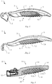
- Fig. 1 a perspective view of a first exemplary embodiment for a fitting part 1 according to the invention is sketched.
- the Fig. 2 same 1 in the side view.
- the attachment 2 which is intended to be attached to the cookware, can be seen.
- the support element 4 which essentially extends over the entire length of the handle part 3 extends.
- the support element 4 of the handle part 3 is covered by a handle element 5, so that only the attachment of the support element 4 facing the attachment part 2 is visible (and can be seen in the figures).
- the handle element 5 an advantageous shape for comfortable handling of the cookware is realized.
- the deformation region 6 according to the invention is now implemented by using a plurality of lamellae 7. These 7 are each fastened to the support element 4 with a foot end 8. In contrast, the individual slats 7 have a free end 9, at which 9 the slats 7 are not connected to one another. The individual lamellae 7 can thus be flexibly deformed with respect to one another.
- the deformation area 6 with the flexible lamellae 7 is implemented by the one-piece grip element 5, which on the one hand covers the support element 4 and also integrally forms the deformation area 6.
- the individual lamellae 7 have a curved shape, the curvature pointing in the direction of the attachment part 2, ie pointing away from the handle part.
- the length of the individual lamellae starting from the first lamella 7.1, which is closest to the attachment 2, increases over the middle lamella 7.5 to the last lamella 7.9.
- the inclination of the individual lamellae 7 is also increased, starting from the first lamella 7.1 via the middle lamella 7.5 to the last lamella 7.9 relative to the position of the handle part 3, the lamellae 7 correspondingly increasing in alignment with increasing distance from the attachment part 2 of the handle part 3 approach.
- FIG Fig. 3 An alternative embodiment for a fitting part 11 according to the invention is outlined in FIG Fig. 3 .
- the handle part 13 can now be detached from the attachment part 12.
- a rigid support element 14 is initially used in the handle part 13 used.
- This 14 can be produced both as a die-cast component or, particularly advantageously, as a plastic injection-molded component and can thus be adapted to an ergonomic shape.
- a plurality of lamellae 17 are arranged on the underside of the handle part 13 on the support element 14, which in this exemplary embodiment are directly injection-molded.
- the individual slats 17 are also attached to the support part 14 by a foot end 18, while the free end 19 of the respective slats is not connected to one another.
- the length of the individual lamellae and the inclination of the lamellae are increased starting from the lamella 17.1 lying closest to the attachment 12 via the middle lamella 17.5 up to the last lamella 17.9.
- a further embodiment of a fitting part 21 is shown, wherein in Fig. 5 this 21 is sketched in a side view.
- the round shape of the fitting part 21 can be seen, which 21 is intended in particular for use as a handle for a saucepan lid.
- the fitting part 21 is formed on the underside by a rigid support element 24, which 24 is advantageously designed as a plastic injection-molded component for this purpose.
- the support element 24 can be fastened directly to the saucepan lid with a screw.
- the support element 24 is covered by a grip element 25, which in this case is injected directly onto the support element 24.
- the grip element 25 integrally comprises the two opposing deformation regions 26a and 26b.
- Each deformation area is formed by a plurality of successive lamellae 27a, 27b, which 27 are in turn fastened to the support element 24 by a foot end 28.
- the ends of the slats 27 opposite the foot end 28 each form a free end 29 at which 29 these 27 are not connected to one another.
- the lamellae 27 have a curved shape pointing away from the support element 24.
- the lamellae 27 are oriented so as to be inclined relative to a tangent on the support element 24.
Landscapes
- Engineering & Computer Science (AREA)
- Food Science & Technology (AREA)
- Cookers (AREA)
- Frying-Pans Or Fryers (AREA)
- Food-Manufacturing Devices (AREA)
Description
- Die Erfindung betrifft ein Beschlagteil zur Befestigung an einem Kochgeschirr, beispielsweise einer Bratpfanne oder einem Kochtopf oder einem Kochtopfdeckel, mit einem Anbauteil, das am Kochgeschirr befestigt werden kann, gemäß dem Oberbegriff des Anspruch 1.
- Beschlagteile zur Verwendung bei Kochgeschirren sind in vielfältiger Ausführungsform aus dem Stand der Technik bekannt. Einerseits werden hierzu vollständig aus Metall hergestellte Beschlagteile verwendet, bei denen das Anbauteil zur Befestigung am Kochgeschirr und das Griffteil einstückig oder mehrteilig miteinander verschweißt ausgeführt sind. Wenngleich die metallische Ausführungsform einen Vorteil hinsichtlich der Robustheit und der Reinigbarkeit des Beschlagteils aufweist, so ist dies mit einem Nachteil hinsichtlich der komfortablen Handhabung des Kochgeschirrs verbunden. Weiterhin sind aus dem Stand der Technik Ausführungsformen von Beschlagteilen bekannt, bei denen das Anbauteil aus einem metallischen Werkstoff hergestellt ist, während hingegen das Griffteil von einem Spritzgussbauteil gebildet wird. In dieser Ausführungsform ist eine bessere ergonomische Anpassung an die Handform möglich, so dass eine komfortable Handhabung des Kochgeschirrs ermöglicht werden kann. Hierbei kann einerseits vorgesehen sein, dass das Griffteil fest mit dem Anbauteil verbunden ist - wie beispielsweise in der
EP 1 477 096 A1 ausgeführt. Ebenso sind beispielsweise aus den SchriftenEP 2 249 687 A1 sowie aus derWO 2012/150192 A1 Beschlagteile bekannt, bei denen das Griffteil bestimmungsgemäß vom Anbauteil abgenommen werden kann. - Darüber hinaus sind Ausführungsformen aus dem Stand der Technik bekannt, bei dem sich das am Kochgeschirr zu befestigende Anbauteil, das aus einem metallischen Werkstoff hergestellt ist, als Tragelement innerhalb des Griffteils fortsetzt. Zur komfortablen Handhabung des Kochgeschirrs ist hierbei das Tragelement mit einem weich elastischen Kunststoff umgeben, so dass eine gewisse Anpassung an die jeweilige Handform beim Ergreifen des Griffteils erfolgen kann.
- Die
EP 0 449 554 A1 beschreibt ein Beschlagteil zur Handhabung eines Haushaltsgeräts. Am Griff dieses Beschlagteils sind verformbare Lamellen angeformt, die eine Grifffläche für den Benutzer bilden. - Wenngleich mit vorgenannter Ausführungsform bereits eine komfortable Handhabung des Kochgeschirrs ermöglicht wird, gilt es dennoch die Ausführungsform hinsichtlich einer sicheren und zugleich komfortablen Handhabung des Kochgeschirrs weiter zu verbessern.
- Die gestellte Aufgabe wird durch eine erfindungsgemäße Ausführungsform nach der Lehre des Anspruchs 1 gelöst.
- Vorteilhafte Ausführungsformen sind Gegenstand der Unteransprüche.
- Das gattungsgemäße Beschlagteil dient zunächst einmal zur Handhabung eines Kochgeschirrs. Hierbei kann es sich beispielsweise um eine Bratpfanne oder einen Kochtopf oder einen Kochtopfdeckel handeln. In welcher Art und Weise das Beschlagteil mit dem Kochgeschirr verbunden wird, ist zunächst unerheblich. Zumindest umfasst das Beschlagteil zunächst einmal ein Tragelement, das biegesteif ausgeführt ist und die Handhabung des Kochgeschirrs beim Ergreifen des Beschlagteils ermöglicht. Hierzu ist das Tragelement unmittelbar oder mittelbar am Kochgeschirr zu befestigen.
- Zur komfortablen Handhabung weist das gattungsgemäße Beschlagteil weiterhin einen Verformungsbereich auf, der fest mit dem Tragelement verbunden ist. Aufgrund einer elastischen Verformbarkeit wird eine Anpassung an die Hand des jeweiligen Verwenders ermöglicht.
- Eine Verbesserung gegenüber der bekannten Ausführungsform mit einem Verformungsbereich wird erfindungsgemäß gattungsgemäße erzielt, indem zur Bildung des Verformungsbereichs eine Mehrzahl zueinander beabstandeter Lamellen eingesetzt wird. Die jeweiligen Lamellen weisen hierbei jeweils ein Fußende auf, das unmittelbar oder mittelbar am Tragelement befestigt ist. Demgegenüber bildet das vom Tragelement beabstandete Ende der jeweiligen Lamelle ein freies Ende, wobei die Lamellen mit ihren freien Enden nicht miteinander verbunden sind.
- Durch die Verwendung einer Mehrzahl nebeneinander angeordneter Lamellen wird eine verbesserte Anpassung an die Hand des jeweiligen Verwenders bei der Gewährleistung eines sicheren Halts des Kochgeschirrs ermöglicht. Darüber hinaus ermöglicht die neuartige Ausführungsform des Verformungsbereichs eine außergewöhnliche Gestaltung des Griffteils, so dass eine charakteristische Unterscheidung zu den üblichen Ausführungsformen von Beschlagteilen möglich wird.
- Hierbei ist es weiterhin gattungsgemäß vorgesehen, dass beim Ergreifen des Beschlagteils und der Belastung der elastisch verformbaren Lamellen diese im Bereich des freien Endes aneinander schuppenartig zur Anlage kommen.
- Der scheinbare Widerspruch zwischen der vom Fußende zum freien Ende hin reduzierten Materialstärke und dem vom Fußende zum freien Ende reduzierten Abstand wird aufgelöst, wenn erfindungsgemäß Lamellen mit einer gewölbten Gestalt verwendet werden. Hierbei werden die Lamellen mit einer zwischen dem Fußende und dem freien Ende liegenden Wölbung ausgeführt, welche zur Außenseite weisend ausbildet ist. Insofern weisen die Lamellen mit ihrer vorwiegend nach außen weisende Seite eine konvexe Wölbung auf, während hingegen die gegenüber liegende, weitgehend verdeckt liegende Seite der Lamellen konkav gekrümmt ist.
- Weiterhin ist es erfindungsgemäß vorgesehen, dass die Lamellen geneigt ausgerichtet sind. Bei Betrachtung von gewölbten Lamellen bezieht sich die Neigung der Lamellen einerseits auf eine gedachte Verbindungslinie zwischen dem Fußende und dem freien Ende der Lamellen. Sofern das Beschlagteil über die Länge des Verformungsbereichs eine längliche Formgebung aufweist, so bezieht sich die Neigung andererseits auf eine gedachte Mittellinie durch das Beschlagteil (zumindest auf der Länge des Verformungsbereichs). Sofern das Beschlagteil bereits eine gewölbte Formgebung aufweist, so bezieht sich die die Neigung anderseits auf eine gedachte Tangente am Beschlagteil jeweils am Fußende der jeweiligen Lamelle. Durch die geneigte Ausführungsform der Lamellen relativ zum Beschlagteil wird die leichte Verformung der Lamellen beim Ergreifen des Beschlagteils ermöglicht.
- Eine vorteilhafte Verformbarkeit der Lamellen wird erzielt, wenn diese in bevorzugter Weise jeweils eine Länge vom Fußende bis zum freien Ende zwischen 10 mm und 50 mm aufweisen. Besonders vorteilhaft ist hierbei eine Länge der Lamellen zwischen 15 mm und 35 mm. Somit wird einerseits ein sicherer Halt gewährleistet als auch ebenso die erforderliche Verformbarkeit der Lamellen ermöglicht wird.
- Weiterhin wird unter Berücksichtigung der Handhabung des Kochgeschirrs bei Ergreifen des Beschlagteils ein vorteilhafter Halt bei komfortabler Anpassung durch die Elastizität der Lamellen erzielt, wenn die Länge der Lamellen ausgehend von einer ersten Lamelle zumindest bis zu einer mittleren Lamelle (in der Reihe der aufeinander folgenden Lamellen von der ersten Lamelle bis zu einer letzten Lamelle) zunimmt. Dies führt zu einer geringeren Flexibilität der ersten Lamelle und einer größeren Flexibilität der mittleren Lamellen. Hierbei ist es besonders vorteilhaft, wenn die Länge der Lamellen über die mittlere Lamelle hinaus bis zur letzten Lamelle zunimmt. Die Erhöhung der Länge der Lamellen dient insbesondere der Änderung der Elastizität der einzelnen Lamellen, die somit ausgehend von der ersten Lamelle über die mittlere Lamelle bis zur letzten Lamelle zunimmt.
- Eine vorteilhafte Formgebung der Lamellen unter Berücksichtigung der Verformung der einzelnen Lamellen wird erzielt, wenn diese am Fußende eine Materialstärke zwischen 2 mm und 6 mm aufweisen, wobei sich die Materialstärke zum freien Ende hin auf einen Wert im Bereich zwischen 1 mm und 3 mm reduziert.
- Zur komfortablen Handhabung ist es weiterhin vorteilhaft, wenn der Abstand der Lamellen nicht zu groß gewählt wird, jedoch eine hinreichende Elastizität durch Verformung der einzelnen Lamellen ermöglicht. Dies wird vorteilhaft gewährleistet, wenn der Abstand zwischen zwei Lamellen an deren Fußende zwischen 2 mm und 6 mm beträgt, wobei im unbelasteten Zustand der Abstand zwischen zwei Lamellen am freien Ende zwischen 1 mm und 3 mm beträgt.
- Darüber hinaus ist es besonders vorteilhaft, wenn die Neigung der Lamellen ausgehend von der mittleren Lamelle hin zur letzten Lamelle zunimmt und sich somit zunehmend die Ausrichtung der Lamellen an der Ausrichtung des Beschlagteils annähert. Dabei ist es besonders vorteilhaft, wenn die Neigung der Lamellen ausgehend von der ersten Lamelle bis zur letzten Lamelle zunimmt.
- Zur Realisierung des am Tragelement befestigten Verformungsbereichs stehen verschiedene Ausführungen zur Verfügung, wobei sich die vorteilhafte Wahl zum einen an die Befestigungsart des Beschlagteils am Kochgeschirr und zum anderen an der geforderten Oberfläche des Beschlagteils richten kann.
- Hierzu ist es in einer ersten Ausführungsform besonders vorteilhaft, wenn das Tragelement von einem Griffelement umgeben ist, das den Verformungsbereich einstückig umfasst. Hierzu wird das Griffelement als separates Teil hergestellt und nachfolgend auf dem Tragelement befestigt. Da der Verformungsbereich im Wesentlichen auf Druck beansprucht wird, ist es diesbezüglich unerheblich, dass die Lamellen mit dem Fußende nicht unmittelbar am Tragelement befestigt sind, sondern sich lediglich am Tragelement abstützen. Diese Ausführungsform ist insbesondere in den Fällen zu bevorzugen, wenn das Tragelement aus einem im Wesentlichen flächigen Blechteil hergestellt ist.
- In einer zweiten Ausführungsform ist es hingegen besonders vorteilhaft, wenn der Verformungsbereich am Tragelement angespritzt wird. Diese Ausführung kann auch bei Verwendung eines aus Metall hergestellten Tragelements eingesetzt werden. Jedoch wird diese Ausführung insbesondere in den Fällen zu bevorzugen sein, wenn das Tragelement aus einem Kunststoff-Spritzgussbauteil hergestellt wird. Somit kann in einem 2K-Verfahren eine feste Verbindung zwischen dem biegesteifen Tragteil und dem elastisch verformbaren Verformungsbereich realisiert werden.
- In der Umsetzung der zweiten Ausführungsform ist es einerseits möglich, den aus einem elastisch verformbaren Material gebildeten Bereich auf die Lamellen zu beschränken. Anderseits können auch weitere Bereiche des Tragteils vom elastisch verformbaren Material überspritzt werden, so dass beispielsweise eine zur Sichtseite geschlossene Oberfläche aus dem elastisch verformbaren Material realisiert wird (und somit dem Erscheinungsbild des montierten Griffelements entspricht).
- In der Verwendung beispielsweise als Griff für einen Kochtopfdeckel kann vorgesehen sein, dass das Tragelement unmittelbar am Kochtopfdeckel befestigt wird. Hierzu wird in aller Regel das Tragelement unterseitig mit einer Gewindebohrung versehen, so dass eine Befestigung mit einer den Deckel durchgreifenden Schraube erfolgen kann.
- In der Verwendung als Griff für einen Kochtopf sind in aller Regel beidseitig Anbauteile erforderlich, welche am Kochtopf befestigt werden können. Wie die Befestigung des Anbauteils erfolgt, ist hinsichtlich der Realisierung der Erfindung unerheblich. Dies kann beispielsweise durch Schweißen, Löten oder Nieten erfolgen. Zumindest wird in diesen Fällen in aller Regel ein Beschlagteil eingesetzt, bei dem das Tragelement fest mit den Anbauteilen verbunden ist, wobei wiederum in aller Regel eine einstückige Ausführung von Tragelement mit Anbauteilen vorzufinden ist. Jedoch kann das Beschlagteil ebenso realisiert werden, indem an beiden Enden des Tragelements ein Anbauteil angebaut wird.
- Bei der Verwendung beispielsweise für eine Bratpfanne weist das Beschlagteil in aller Regel ein Anbauteil auf, welches an der Bratpfanne befestigt wird. Diesbezüglich ist es wiederum unerheblich, ob die bestimmungsgemäße Anbringung an der Bratpfanne durch Schweißen, Löten oder Nieten erfolgt. Gleichfalls wie bei der Ausführung von Beschlagteilen für Kochtöpfe mit zwei Anbauteilen sind Ausführungen möglich, bei denen das Anbauteil fest mit dem Tragelement verbunden ist. Hierzu kann analog vorgesehen sein, dass das Tragelement und das Anbauteil einstückig ausgeführt sind oder dass alternativ das Tragelement - beispielsweise nach Anbringung des Anbauteils am Kochgeschirr - am Anbauteil befestigt wird.
- Im Gegensatz zur Verwendung des Griffes für Kochtöpfe mit zwei fest verbundenen Anbauteilen sind jedoch ebenso Ausführungen möglich, bei denen das Tragelement vom Verwender des Kochgeschirrs vom Anbauteil abnehmbar ist. Bei dieser Ausführungsform bildet das Tragelement mit dem Verformungsbereich ein Griffteil, welches vom Verwender bei Bedarf am zum Beschlagteil gehörenden Anbauteil angebracht oder abgenommen werden kann.
- Hinsichtlich der Anordnung des Verformungsbereichs ist es besonders vorteilhaft, wenn der Verformungsbereich bei Verwendung des Beschlagteils für einen Kochtopf, eine Bratpfanne oder dergleichen an der Unterseite des Tragelements angeordnet ist. Somit wird ein sicherer Halt des Kochgeschirrs bei Ergreifen des Griffteils und zudem eine komfortable Anpassung an die Hand des jeweiligen Verwenders erzielt.
- Weiterhin ist es bei Verwendung des Beschlagteils mit einem einzelnen Anbauteil, d. h. in der Regel für eine Bratpfanne oder dergleichen, besonders vorteilhaft, wenn die freien Enden bei der geneigten Ausrichtung der Lamellen vom Anbauteil wegweisend ausgerichtet sind.
- In den nachfolgenden Figuren werden zwei beispielhafte Ausführungsformen für ein erfindungsgemäßes Beschlagteil skizziert.
- Es zeigen:
- Fig. 1
- eine perspektivische Ansicht auf eine erste Ausführungsform eines Beschlagteils ohne abnehmbarem Griffteil;
- Fig. 2
- eine Seitenansicht zu der Ausführungsform aus
Fig. 1 ; - Fig. 3
- eine alternative Ausführungsform eines Beschlagteils mit einem abnehmbaren Griffteil;
- Fig. 4
- eine perspektivische Ansicht auf eine Ausführungsform zur Verwendung als Griff für Kochtopfdeckel;
- Fig. 5
- eine Seitenansicht zur der Ausführungsform aus
Fig. 4 . - In
Fig. 1 wird eine perspektivische Ansicht auf eine erste beispielhafte Ausführungsform für ein erfindungsgemäßes Beschlagteil 1 skizziert. Hierzu zeigt dieFig. 2 selbiges 1 in der Seitenansicht. Zu erkennen ist zunächst einmal das Anbauteil 2, das zur Befestigung am Kochgeschirr bestimmt ist. Einstückig mit dem Anbauteil 2 verbunden ist in diesem Ausführungsbeispiel das Tragelement 4, das sich im Wesentlichen über die gesamte Länge des Griffteils 3 erstreckt. Hierbei wird das Tragelement 4 des Griffteils 3 von einem Griffelement 5 überdeckt, so dass für den Verwender lediglich der zum Anbauteil 2 weisende Ansatz des Tragelements 4 sichtbar wird (und in den Figuren zu erkennen ist). Mit dem Griffelement 5 wird eine vorteilhafte Formgebung zur komfortablen Handhabung des Kochgeschirrs realisiert. - Der erfindungsgemäße Verformungsbereich 6 wird nunmehr durch den Einsatz einer Mehrzahl an Lamellen 7 realisiert. Diese 7 sind jeweils mit einem Fußende 8 am Tragelement 4 befestigt. Demgegenüber weisen die einzelnen Lamellen 7 ein freies Ende 9 auf, an denen 9 die Lamellen 7 nicht miteinander verbunden sind. Somit können die einzelnen Lamellen 7 flexibel zueinander verformt werden. Die Realisierung des Verformungsbereichs 6 mit den flexiblen Lamellen 7 erfolgt in diesem Ausführungsbeispiel durch das einstückige Griffelement 5, das einerseits das Tragelement 4 überdeckt und zudem integral den Verformungsbereich 6 bildet.
- Darüber hinaus ist zu erkennen, dass die einzelnen Lamellen 7 eine gewölbte Formgebung aufweisen, wobei sich die Wölbung in Richtung des Anbauteils 2 weist, d. h. vom Griffteil wegweisend. Zudem ist insbesondere aus der
Fig. 2 zu erkennen, dass die Länge der einzelnen Lamellen ausgehend von der ersten Lamelle 7.1, die dem Anbauteil 2 am nächsten liegt, über die mittlere Lamelle 7.5 bis zur letzten Lamelle 7.9 zunimmt. Darüber hinaus wird zudem die Neigung der einzelnen Lamellen 7 ebenso ausgehend von der ersten Lamelle 7.1 über die mittlere Lamelle 7.5 bis zur letzten Lamelle 7.9 relativ zur Lage des Griffteils 3 gesteigert, wobei sich entsprechend die Lamellen 7 mit zunehmendem Abstand vom Anbauteil 2 an die Ausrichtung des Griffteils 3 annähern. - Eine alternative Ausführungsform für ein erfindungsgemäßes Beschlagteil 11 skizziert die
Fig. 3 . Im Gegensatz zur vorherigen Ausführungsform ist nunmehr das Griffteil 13 vom Anbauteil 12 lösbar. Hierzu wird beim Griffteil 13 zunächst einmal ein biegesteifes Tragelement 14 eingesetzt. Dieses 14 kann sowohl als Druckgussbauteil oder besonders vorteilhaft als Kunststoff-Spritzgussbauteil hergestellt sein und somit an eine ergonomische Formgebung angepasst werden. - Zur Realisierung eines Verformungsbereichs 16 werden unterseitig im Griffteil 13 eine Mehrzahl von Lamellen 17 am Tragelement 14 angeordnet, die in diesem Ausführungsbeispiel unmittelbar angespritzt sind. Somit wird einerseits eine einfache und vorteilhafte Herstellung ermöglicht, während ebenso ein vorteilhafter Halt gewährleistet ist. Hinsichtlich der Ausrichtung und Formgebung der Lamellen gilt Gleiches wie zuvor gesagt. Die einzelnen Lamellen 17 sind ebenso mit einem Fußende 18 am Tragteil 14 befestigt während das freie Ende 19 der jeweiligen Lamellen nicht miteinander verbunden ist. Ebenso wird die Länge der einzelnen Lamellen als auch die Neigung der Lamellen ausgehend von der dem Anbauteil 12 am nächsten liegenden Lamelle 17.1 über die mittlere Lamelle 17.5 bis zu letzten Lamelle 17.9 gesteigert.
- In der
Fig. 4 wird eine weitere Ausführungsform eines Beschlagteils 21 dargestellt, wobei inFig. 5 diese 21 in einer Seitenansicht skizziert wird. Zu erkennen ist die runde Gestalt des Beschlagteils 21, welches 21 insbesondere zur Verwendung als Griff für einen Kochtopfdeckel bestimmt ist. Das Beschlagteil 21 wird unterseitig von einem biegesteifen Tragelement 24 gebildet, welches 24 hierzu vorteilhaft als Kunststoff-Spritzguss-Bauteil ausgeführt wird. Das Tragelement 24 kann unmittelbar auf dem Kochtopfdeckel mit einer Schraube befestigt werden. Oberseitig wird das Tragelement 24 von einem Griffelement 25 überdeckt, welches 25 in diesem Fall unmittelbar auf dem Tragelement 24 aufgespritzt ist. Hierbei umfasst das Griffelement 25 einstückig die beiden gegenüberliegenden Verformungsbereiche 26a und 26b. - Jeder Verformungsbereich wird von einer Mehrzahl aufeinander folgenden Lamellen 27a, 27b gebildet, welche 27 wiederum mit einem Fußende 28 am Tragelement 24 befestigt sind. Demgegenüber bilden die dem Fußende 28 gegenüberliegenden Enden der Lamellen 27 jeweils ein freies Ende 29, an denen 29 diese 27 nicht miteinander verbunden sind. Analog der vorhergehenden Beispiele weisen die Lamellen 27 eine gewölbte, vom Tragelement 24 wegweisende Formgebung auf. Ebenso sind die Lamellen 27 relativ zu einer Tangente am Tragelement 24 geneigt ausgerichtet.
Claims (10)
- Beschlagteil (1, 11, 21) zur Handhabung eines Kochgeschirrs, mit einem biegesteifen Tragelement (4, 14), welches (4, 14) unmittelbar oder mittelbar am Kochgeschirr befestigt werden kann, und mit zumindest einem am Tragelement (4, 14) angeordneten elastisch verformbaren Verformungsbereich (6, 16, 26a, 26b),
wobei der Verformungsbereich (6, 16, 26a, 26b) von einer Mehrzahl zueinander beabstandeter Lamellen (7, 17, 27a, 27b) gebildet wird, welche (7, 17, 27a, 27b) jeweils mit einem Fußende (8, 18, 28) unmittelbar oder mittelbar am Tragelement (4, 14) befestigt sind und ein vom Tragelement (4, 14) beabstandetes freies Ende (9, 19, 29) aufweisen, und wobei sich die Lamellen (7, 17, 27) bei Belastung zumindest im Bereich des freien Endes (9, 19, 29) schuppenartig aneinander anlegen
dadurch gekennzeichnet,
dass die Lamellen (7, 17, 27) zwischen dem Fußende (8, 18, 28) und dem freien Ende (9, 19, 29) nach außen weisend gewölbt ausgeführt sind, wobei die Lamellen (7, 17, 27) geneigt ausgeführt sind. - Beschlagteil (1, 11, 21) nach Anspruch 1,
dadurch gekennzeichnet,
dass die Längen der Lamellen (7, 17, 27) vom Fußende (8, 18, 28) bis zum freien Ende (9, 19, 29) zwischen 10 mm, insbesondere 15 mm, und 50 mm, insbesondere 35 mm, betragen. - Beschlagteil (1, 11, 21) nach einem der Ansprüche 1 oder 2,
dadurch gekennzeichnet,
dass die Länge der aufeinander folgenden Lamellen (7, 17) ausgehend von einer ersten Lamelle (7.1, 17.1), wobei die erste Lamelle (7.1, 17.1) dem Kochgeschirr am nächsten liegt, zumindest bis zur mittleren Lamelle (7.5, 17.5), insbesondere bis zur letzten Lamelle (7.9, 17.9), wobei die letzte Lamelle (7.9, 17.9) von dem Kochgeschirr am weitesten entfernt ist, zunimmt. - Beschlagteil (1, 11, 21) nach einem der Ansprüche 1 bis 3,
dadurch gekennzeichnet,
dass die Lamellen (7, 17, 27) am Fußende (8, 18, 28) eine Materialstärke zwischen 2 mm und 6 mm aufweisen, wobei sich die Materialstärke zum freien Ende (9, 19, 29) hin auf 1 mm bis 3 mm reduziert. - Beschlagteil (1, 11, 21) nach einem der Ansprüche 1 bis 4,
dadurch gekennzeichnet,
dass der Abstand zwischen zwei Lamellen (7, 17, 27) an deren Fußende (8, 18, 28) zwischen 2 mm und 6 mm beträgt, wobei im unbelasteten Zustand der Abstand zwischen zwei Lamellen (7, 17, 27) am freien Ende (9, 19, 29) zwischen 1 mm bis 3 mm beträgt. - Beschlagteil (1, 11) nach einem der Ansprüche 1 bis 5,
dadurch gekennzeichnet,
dass die Neigung der aufeinander folgenden Lamellen (7, 17) ausgehend, insbesondere von der ersten Lamelle (7.1, 17.1), wobei die erste Lamelle (7.1, 17.1) dem Kochgeschirr am nächsten liegt, zumindest ab der mittleren Lamelle (7.5, 17.5) bis zur letzten Lamelle (7.9, 17.9), wobei die letzte Lamelle (7.9, 17.9) von dem Kochgeschirr am weitesten entfernt ist, zunimmt. - Beschlagteil (1) nach einem der Ansprüche 1 bis 6,
dadurch gekennzeichnet,
dass das Tragelement (4) von einem auf diesem (4) befestigtem Griffelement (5) umgeben ist, welches (5) den Verformungsbereich (6) einstückig umfasst. - Beschlagteil (11, 21) nach einem der Ansprüche 1 bis 7,
dadurch gekennzeichnet,
dass das Tragelement (14) als Spritzgussbauteil ausgeführt ist, wobei die Lamellen (17) am Tragelement (14) angespritzt sind; oder
dass das Tragelement (14) als Spritzgussbauteil ausgeführt ist, wobei das Tragelement (24) von einem auf diesem (24) im Spritzgussverfahren aufgebrachten Griffelement (25) umgeben ist, welches (25) den Verformungsbereich (26) einstückig umfasst. - Beschlagteil (1, 11) nach einem der Ansprüche 1 bis 8,
dadurch gekennzeichnet,
dass am Tragelement (4, 14) zumindest ein Anbauteil (2, 12) angeordnet ist, welches (2, 12) lösbar oder fest am Kochgeschirr befestigt werden kann. - Beschlagteil (1, 11) nach Anspruch 9,
dadurch gekennzeichnet,
dass die Lamellen (7, 17) mit deren (7, 17) freien Enden (9, 19) vom Anbauteil (02, 12) wegweisend ausgeführt sind.
Applications Claiming Priority (2)
| Application Number | Priority Date | Filing Date | Title |
|---|---|---|---|
| DE102015202428.8A DE102015202428A1 (de) | 2015-02-11 | 2015-02-11 | Beschlagteil zur Befestigung an einem Kochgeschirr |
| PCT/EP2016/052365 WO2016128286A1 (de) | 2015-02-11 | 2016-02-04 | Beschlagteil zur befestigung an einem kochgeschirr |
Publications (2)
| Publication Number | Publication Date |
|---|---|
| EP3136918A1 EP3136918A1 (de) | 2017-03-08 |
| EP3136918B1 true EP3136918B1 (de) | 2021-08-25 |
Family
ID=55436068
Family Applications (1)
| Application Number | Title | Priority Date | Filing Date |
|---|---|---|---|
| EP16706319.7A Active EP3136918B1 (de) | 2015-02-11 | 2016-02-04 | Beschlagteil zur befestigung an einem kochgeschirr |
Country Status (6)
| Country | Link |
|---|---|
| US (1) | US20170332846A1 (de) |
| EP (1) | EP3136918B1 (de) |
| CN (1) | CN107257646A (de) |
| DE (1) | DE102015202428A1 (de) |
| PT (1) | PT3136918T (de) |
| WO (1) | WO2016128286A1 (de) |
Citations (1)
| Publication number | Priority date | Publication date | Assignee | Title |
|---|---|---|---|---|
| EP0449554A1 (de) * | 1990-03-26 | 1991-10-02 | General Housewares Corp. | Universalhandgriff für Handgerät |
Family Cites Families (37)
| Publication number | Priority date | Publication date | Assignee | Title |
|---|---|---|---|---|
| GB390272A (en) * | 1931-12-29 | 1933-04-06 | David Wilson | A new or improved device for fitting to the handles or knobs of glass dishes or receptacles and the like |
| US2144474A (en) * | 1936-09-23 | 1939-01-17 | Westinghouse Electric & Mfg Co | Ventilated handle for sadirons |
| US2133252A (en) * | 1936-10-26 | 1938-10-11 | Moore Enameling & Mfg Company | Handle for cooking utensil |
| US2231222A (en) * | 1939-06-26 | 1941-02-11 | Kewaskum Aluminum Company | Handle for cooking utensils |
| US2431808A (en) * | 1945-07-12 | 1947-12-02 | Johannes F Kluit | Pan handle |
| US3119143A (en) * | 1961-08-30 | 1964-01-28 | Francis J Gorman | Cool knob for handling hot elements |
| US4197611A (en) * | 1978-09-14 | 1980-04-15 | Lincoln Manufacturing Company, Inc. | Hand grip for cooking utensil handle |
| US4372361A (en) * | 1980-05-19 | 1983-02-08 | Carl Whiteford | Multi-purpose turning tool |
| USD267147S (en) * | 1980-12-08 | 1982-12-07 | Oakley, Inc. | Grip for bicycles, motorcycles or the like |
| US4785495A (en) * | 1987-08-17 | 1988-11-22 | Dellis Edward A | Moldable hand grips |
| US5097566A (en) * | 1987-10-07 | 1992-03-24 | Bettcher Industries, Inc. | Slip-resistant cushioning covers for handles |
| USD337505S (en) * | 1991-10-22 | 1993-07-20 | Chen Ming-Chang | Bicycle handlebar |
| US5867867A (en) * | 1996-05-01 | 1999-02-09 | The Vollrath Company, Inc. | Pan handle hand grip |
| US5992540A (en) * | 1998-03-06 | 1999-11-30 | Snap-On Tools Company | Air ratchet hand tool with thermoplastic jacket |
| USD436829S1 (en) * | 1999-09-10 | 2001-01-30 | Isaberg Rapid Ab | Tool handle |
| USD453465S1 (en) * | 2001-06-13 | 2002-02-12 | Ching-Fong Hsieh | Hand power puller handle |
| USD465716S1 (en) * | 2002-01-23 | 2002-11-19 | Ching-Fong Hsieh | Hand power puller handle |
| US7410076B2 (en) * | 2003-05-08 | 2008-08-12 | Borhofen Robert H | Self-releasing, heat insulating pan-handle holder |
| DE10322409A1 (de) | 2003-05-16 | 2004-12-09 | Heinrich Baumgarten KG, Spezialfabrik für Beschlagteile | Gefäß mit einem an der Außenseite des Gefäßes befestigbaren Griffkörper |
| US7930804B2 (en) * | 2003-12-30 | 2011-04-26 | Randall Cornfield | Implement handle |
| US7284300B1 (en) * | 2004-01-02 | 2007-10-23 | Bruns Nancy L | Grip for a handle |
| US6976405B2 (en) * | 2004-03-12 | 2005-12-20 | Medical Associates, Inc. | Detachment tool |
| US7490732B2 (en) * | 2005-03-25 | 2009-02-17 | The Vollrath Company, L.L.C. | Handle |
| US20060237470A1 (en) * | 2005-04-25 | 2006-10-26 | Zanner Kurt H | Cookware handle holder |
| US7624893B2 (en) * | 2006-03-28 | 2009-12-01 | Access Business Group International Llc | Cookware handle with metal insert and overmold |
| USD573867S1 (en) * | 2007-02-28 | 2008-07-29 | Fluke Corporation | Handle device |
| DE102008005567B4 (de) | 2008-01-22 | 2011-12-22 | Heinrich Baumgarten KG Spezialfabrik für Beschlagteile | Beschlagteil zur Befestigung an einem Koch- oder Bratgefäß |
| US20090271951A1 (en) * | 2008-05-05 | 2009-11-05 | Wen Hao | Hand grips with gel stress relieving inserts |
| US8151468B2 (en) * | 2008-09-26 | 2012-04-10 | The Gillette Company | Handle for shaving razors having improved grip |
| USD613005S1 (en) * | 2009-02-20 | 2010-03-30 | Han Lien International Corp. | Grip for pet comb |
| CA132618S (en) * | 2009-05-15 | 2010-06-02 | Pi Design Ag | Garlic press |
| US20120110787A1 (en) * | 2010-11-05 | 2012-05-10 | Clipper Corporation | Implement handle with ergonomic grip providing rotational leverage |
| CN202005632U (zh) * | 2011-03-18 | 2011-10-12 | 江门市安诺特炊具制造有限公司 | 一种应用于锅体上的手柄 |
| DE102011075204B4 (de) | 2011-05-04 | 2014-05-22 | Baumgarten handle systems KG | Beschlagteil zur Befestigung an einem Koch- oder Bratgefäß |
| WO2013130365A1 (en) * | 2012-02-29 | 2013-09-06 | Meyer Intellectual Properties Ltd. | Cookware handle with a soft grip |
| US8844099B2 (en) * | 2012-10-12 | 2014-09-30 | Sp Industries Holdings, Inc. | Handle device |
| USD699070S1 (en) * | 2013-03-13 | 2014-02-11 | Meyer Intellectual Properties Limited | Elongated side handle for cookware |
-
2015
- 2015-02-11 DE DE102015202428.8A patent/DE102015202428A1/de not_active Ceased
-
2016
- 2016-02-04 EP EP16706319.7A patent/EP3136918B1/de active Active
- 2016-02-04 US US15/311,455 patent/US20170332846A1/en not_active Abandoned
- 2016-02-04 WO PCT/EP2016/052365 patent/WO2016128286A1/de not_active Ceased
- 2016-02-04 PT PT16706319T patent/PT3136918T/pt unknown
- 2016-02-04 CN CN201680009747.0A patent/CN107257646A/zh active Pending
Patent Citations (1)
| Publication number | Priority date | Publication date | Assignee | Title |
|---|---|---|---|---|
| EP0449554A1 (de) * | 1990-03-26 | 1991-10-02 | General Housewares Corp. | Universalhandgriff für Handgerät |
Also Published As
| Publication number | Publication date |
|---|---|
| DE102015202428A1 (de) | 2016-08-11 |
| EP3136918A1 (de) | 2017-03-08 |
| PT3136918T (pt) | 2021-10-26 |
| CN107257646A (zh) | 2017-10-17 |
| US20170332846A1 (en) | 2017-11-23 |
| WO2016128286A1 (de) | 2016-08-18 |
Similar Documents
| Publication | Publication Date | Title |
|---|---|---|
| DE102011075204B4 (de) | Beschlagteil zur Befestigung an einem Koch- oder Bratgefäß | |
| DE102014019997B4 (de) | Gargutträger | |
| DE20010037U1 (de) | Schnellbefestigungselement | |
| EP0458254B1 (de) | Befestigungsvorrichtung zur Befestigung eines Griffelementes an einem Kochgeschirr | |
| EP2615380B1 (de) | Garraumeinschub | |
| EP3136918B1 (de) | Beschlagteil zur befestigung an einem kochgeschirr | |
| DE202017102818U1 (de) | Ampullarium mit Federclips | |
| EP2306876B1 (de) | Griffbefestigung | |
| EP2429334B1 (de) | Schnullerband-klammer | |
| DE102014100414B4 (de) | Dunstabzugshaubeneinrichtung | |
| DE102017111608A1 (de) | Küchengerät | |
| DE102020115530A1 (de) | Halterahmen und Steckverbinder mit einem derartigen Halterahmen | |
| DE202014002664U1 (de) | Esshilfe | |
| DE10322409A1 (de) | Gefäß mit einem an der Außenseite des Gefäßes befestigbaren Griffkörper | |
| EP3733024B1 (de) | Greifvorrichtung für küchenanwendungen | |
| DE3716965C2 (de) | ||
| EP1500355B1 (de) | Handgriff eines Haushaltsgerätes | |
| DE29804533U1 (de) | Backofenrost oder Backblech | |
| EP1500363B1 (de) | Handgriff eines Haushaltsgeräts | |
| EP1517629A1 (de) | Abdeckung f r ein kochgeschirr | |
| DE202006014409U1 (de) | Beschlagteil zur Befestigung an einem Koch- oder Bratgefäß | |
| DE102011080190A1 (de) | Hausgeräteanordnung mit einem ersten und zumindest einem zweiten Hausgerät | |
| DE202011000951U1 (de) | Reißverschlusskopf | |
| DD269779A1 (de) | Griff fuer haushaltgeraete | |
| DE9101479U1 (de) | Schrank |
Legal Events
| Date | Code | Title | Description |
|---|---|---|---|
| STAA | Information on the status of an ep patent application or granted ep patent |
Free format text: STATUS: THE INTERNATIONAL PUBLICATION HAS BEEN MADE |
|
| PUAI | Public reference made under article 153(3) epc to a published international application that has entered the european phase |
Free format text: ORIGINAL CODE: 0009012 |
|
| STAA | Information on the status of an ep patent application or granted ep patent |
Free format text: STATUS: REQUEST FOR EXAMINATION WAS MADE |
|
| 17P | Request for examination filed |
Effective date: 20161115 |
|
| AK | Designated contracting states |
Kind code of ref document: A1 Designated state(s): AL AT BE BG CH CY CZ DE DK EE ES FI FR GB GR HR HU IE IS IT LI LT LU LV MC MK MT NL NO PL PT RO RS SE SI SK SM TR |
|
| AX | Request for extension of the european patent |
Extension state: BA ME |
|
| STAA | Information on the status of an ep patent application or granted ep patent |
Free format text: STATUS: EXAMINATION IS IN PROGRESS |
|
| 17Q | First examination report despatched |
Effective date: 20171002 |
|
| DAV | Request for validation of the european patent (deleted) | ||
| DAX | Request for extension of the european patent (deleted) | ||
| GRAP | Despatch of communication of intention to grant a patent |
Free format text: ORIGINAL CODE: EPIDOSNIGR1 |
|
| STAA | Information on the status of an ep patent application or granted ep patent |
Free format text: STATUS: GRANT OF PATENT IS INTENDED |
|
| INTG | Intention to grant announced |
Effective date: 20210325 |
|
| GRAS | Grant fee paid |
Free format text: ORIGINAL CODE: EPIDOSNIGR3 |
|
| GRAA | (expected) grant |
Free format text: ORIGINAL CODE: 0009210 |
|
| STAA | Information on the status of an ep patent application or granted ep patent |
Free format text: STATUS: THE PATENT HAS BEEN GRANTED |
|
| AK | Designated contracting states |
Kind code of ref document: B1 Designated state(s): AL AT BE BG CH CY CZ DE DK EE ES FI FR GB GR HR HU IE IS IT LI LT LU LV MC MK MT NL NO PL PT RO RS SE SI SK SM TR |
|
| REG | Reference to a national code |
Ref country code: CH Ref legal event code: EP |
|
| REG | Reference to a national code |
Ref country code: IE Ref legal event code: FG4D Free format text: LANGUAGE OF EP DOCUMENT: GERMAN Ref country code: AT Ref legal event code: REF Ref document number: 1422913 Country of ref document: AT Kind code of ref document: T Effective date: 20210915 |
|
| REG | Reference to a national code |
Ref country code: DE Ref legal event code: R096 Ref document number: 502016013690 Country of ref document: DE |
|
| REG | Reference to a national code |
Ref country code: PT Ref legal event code: SC4A Ref document number: 3136918 Country of ref document: PT Date of ref document: 20211026 Kind code of ref document: T Free format text: AVAILABILITY OF NATIONAL TRANSLATION Effective date: 20211018 |
|
| REG | Reference to a national code |
Ref country code: LT Ref legal event code: MG9D |
|
| REG | Reference to a national code |
Ref country code: NL Ref legal event code: MP Effective date: 20210825 |
|
| PG25 | Lapsed in a contracting state [announced via postgrant information from national office to epo] |
Ref country code: RS Free format text: LAPSE BECAUSE OF FAILURE TO SUBMIT A TRANSLATION OF THE DESCRIPTION OR TO PAY THE FEE WITHIN THE PRESCRIBED TIME-LIMIT Effective date: 20210825 Ref country code: SE Free format text: LAPSE BECAUSE OF FAILURE TO SUBMIT A TRANSLATION OF THE DESCRIPTION OR TO PAY THE FEE WITHIN THE PRESCRIBED TIME-LIMIT Effective date: 20210825 Ref country code: LT Free format text: LAPSE BECAUSE OF FAILURE TO SUBMIT A TRANSLATION OF THE DESCRIPTION OR TO PAY THE FEE WITHIN THE PRESCRIBED TIME-LIMIT Effective date: 20210825 Ref country code: BG Free format text: LAPSE BECAUSE OF FAILURE TO SUBMIT A TRANSLATION OF THE DESCRIPTION OR TO PAY THE FEE WITHIN THE PRESCRIBED TIME-LIMIT Effective date: 20211125 Ref country code: NO Free format text: LAPSE BECAUSE OF FAILURE TO SUBMIT A TRANSLATION OF THE DESCRIPTION OR TO PAY THE FEE WITHIN THE PRESCRIBED TIME-LIMIT Effective date: 20211125 Ref country code: FI Free format text: LAPSE BECAUSE OF FAILURE TO SUBMIT A TRANSLATION OF THE DESCRIPTION OR TO PAY THE FEE WITHIN THE PRESCRIBED TIME-LIMIT Effective date: 20210825 Ref country code: ES Free format text: LAPSE BECAUSE OF FAILURE TO SUBMIT A TRANSLATION OF THE DESCRIPTION OR TO PAY THE FEE WITHIN THE PRESCRIBED TIME-LIMIT Effective date: 20210825 Ref country code: HR Free format text: LAPSE BECAUSE OF FAILURE TO SUBMIT A TRANSLATION OF THE DESCRIPTION OR TO PAY THE FEE WITHIN THE PRESCRIBED TIME-LIMIT Effective date: 20210825 |
|
| PG25 | Lapsed in a contracting state [announced via postgrant information from national office to epo] |
Ref country code: PL Free format text: LAPSE BECAUSE OF FAILURE TO SUBMIT A TRANSLATION OF THE DESCRIPTION OR TO PAY THE FEE WITHIN THE PRESCRIBED TIME-LIMIT Effective date: 20210825 Ref country code: LV Free format text: LAPSE BECAUSE OF FAILURE TO SUBMIT A TRANSLATION OF THE DESCRIPTION OR TO PAY THE FEE WITHIN THE PRESCRIBED TIME-LIMIT Effective date: 20210825 Ref country code: GR Free format text: LAPSE BECAUSE OF FAILURE TO SUBMIT A TRANSLATION OF THE DESCRIPTION OR TO PAY THE FEE WITHIN THE PRESCRIBED TIME-LIMIT Effective date: 20211126 |
|
| PG25 | Lapsed in a contracting state [announced via postgrant information from national office to epo] |
Ref country code: NL Free format text: LAPSE BECAUSE OF FAILURE TO SUBMIT A TRANSLATION OF THE DESCRIPTION OR TO PAY THE FEE WITHIN THE PRESCRIBED TIME-LIMIT Effective date: 20210825 |
|
| PG25 | Lapsed in a contracting state [announced via postgrant information from national office to epo] |
Ref country code: DK Free format text: LAPSE BECAUSE OF FAILURE TO SUBMIT A TRANSLATION OF THE DESCRIPTION OR TO PAY THE FEE WITHIN THE PRESCRIBED TIME-LIMIT Effective date: 20210825 |
|
| REG | Reference to a national code |
Ref country code: DE Ref legal event code: R097 Ref document number: 502016013690 Country of ref document: DE |
|
| PG25 | Lapsed in a contracting state [announced via postgrant information from national office to epo] |
Ref country code: SM Free format text: LAPSE BECAUSE OF FAILURE TO SUBMIT A TRANSLATION OF THE DESCRIPTION OR TO PAY THE FEE WITHIN THE PRESCRIBED TIME-LIMIT Effective date: 20210825 Ref country code: SK Free format text: LAPSE BECAUSE OF FAILURE TO SUBMIT A TRANSLATION OF THE DESCRIPTION OR TO PAY THE FEE WITHIN THE PRESCRIBED TIME-LIMIT Effective date: 20210825 Ref country code: RO Free format text: LAPSE BECAUSE OF FAILURE TO SUBMIT A TRANSLATION OF THE DESCRIPTION OR TO PAY THE FEE WITHIN THE PRESCRIBED TIME-LIMIT Effective date: 20210825 Ref country code: EE Free format text: LAPSE BECAUSE OF FAILURE TO SUBMIT A TRANSLATION OF THE DESCRIPTION OR TO PAY THE FEE WITHIN THE PRESCRIBED TIME-LIMIT Effective date: 20210825 Ref country code: CZ Free format text: LAPSE BECAUSE OF FAILURE TO SUBMIT A TRANSLATION OF THE DESCRIPTION OR TO PAY THE FEE WITHIN THE PRESCRIBED TIME-LIMIT Effective date: 20210825 Ref country code: AL Free format text: LAPSE BECAUSE OF FAILURE TO SUBMIT A TRANSLATION OF THE DESCRIPTION OR TO PAY THE FEE WITHIN THE PRESCRIBED TIME-LIMIT Effective date: 20210825 |
|
| PGFP | Annual fee paid to national office [announced via postgrant information from national office to epo] |
Ref country code: PT Payment date: 20220203 Year of fee payment: 7 Ref country code: FR Payment date: 20220221 Year of fee payment: 7 |
|
| PLBE | No opposition filed within time limit |
Free format text: ORIGINAL CODE: 0009261 |
|
| STAA | Information on the status of an ep patent application or granted ep patent |
Free format text: STATUS: NO OPPOSITION FILED WITHIN TIME LIMIT |
|
| 26N | No opposition filed |
Effective date: 20220527 |
|
| PG25 | Lapsed in a contracting state [announced via postgrant information from national office to epo] |
Ref country code: SI Free format text: LAPSE BECAUSE OF FAILURE TO SUBMIT A TRANSLATION OF THE DESCRIPTION OR TO PAY THE FEE WITHIN THE PRESCRIBED TIME-LIMIT Effective date: 20210825 |
|
| PG25 | Lapsed in a contracting state [announced via postgrant information from national office to epo] |
Ref country code: MC Free format text: LAPSE BECAUSE OF FAILURE TO SUBMIT A TRANSLATION OF THE DESCRIPTION OR TO PAY THE FEE WITHIN THE PRESCRIBED TIME-LIMIT Effective date: 20210825 |
|
| REG | Reference to a national code |
Ref country code: CH Ref legal event code: PL |
|
| REG | Reference to a national code |
Ref country code: BE Ref legal event code: MM Effective date: 20220228 |
|
| GBPC | Gb: european patent ceased through non-payment of renewal fee |
Effective date: 20220204 |
|
| PG25 | Lapsed in a contracting state [announced via postgrant information from national office to epo] |
Ref country code: LU Free format text: LAPSE BECAUSE OF NON-PAYMENT OF DUE FEES Effective date: 20220204 |
|
| PG25 | Lapsed in a contracting state [announced via postgrant information from national office to epo] |
Ref country code: LI Free format text: LAPSE BECAUSE OF NON-PAYMENT OF DUE FEES Effective date: 20220228 Ref country code: IE Free format text: LAPSE BECAUSE OF NON-PAYMENT OF DUE FEES Effective date: 20220204 Ref country code: GB Free format text: LAPSE BECAUSE OF NON-PAYMENT OF DUE FEES Effective date: 20220204 Ref country code: CH Free format text: LAPSE BECAUSE OF NON-PAYMENT OF DUE FEES Effective date: 20220228 |
|
| PG25 | Lapsed in a contracting state [announced via postgrant information from national office to epo] |
Ref country code: BE Free format text: LAPSE BECAUSE OF NON-PAYMENT OF DUE FEES Effective date: 20220228 |
|
| REG | Reference to a national code |
Ref country code: AT Ref legal event code: MM01 Ref document number: 1422913 Country of ref document: AT Kind code of ref document: T Effective date: 20220204 |
|
| PG25 | Lapsed in a contracting state [announced via postgrant information from national office to epo] |
Ref country code: AT Free format text: LAPSE BECAUSE OF NON-PAYMENT OF DUE FEES Effective date: 20220204 |
|
| P01 | Opt-out of the competence of the unified patent court (upc) registered |
Effective date: 20230523 |
|
| PG25 | Lapsed in a contracting state [announced via postgrant information from national office to epo] |
Ref country code: PT Free format text: LAPSE BECAUSE OF NON-PAYMENT OF DUE FEES Effective date: 20230804 |
|
| PG25 | Lapsed in a contracting state [announced via postgrant information from national office to epo] |
Ref country code: FR Free format text: LAPSE BECAUSE OF NON-PAYMENT OF DUE FEES Effective date: 20230228 |
|
| PG25 | Lapsed in a contracting state [announced via postgrant information from national office to epo] |
Ref country code: HU Free format text: LAPSE BECAUSE OF FAILURE TO SUBMIT A TRANSLATION OF THE DESCRIPTION OR TO PAY THE FEE WITHIN THE PRESCRIBED TIME-LIMIT; INVALID AB INITIO Effective date: 20160204 |
|
| PG25 | Lapsed in a contracting state [announced via postgrant information from national office to epo] |
Ref country code: MK Free format text: LAPSE BECAUSE OF FAILURE TO SUBMIT A TRANSLATION OF THE DESCRIPTION OR TO PAY THE FEE WITHIN THE PRESCRIBED TIME-LIMIT Effective date: 20210825 Ref country code: CY Free format text: LAPSE BECAUSE OF FAILURE TO SUBMIT A TRANSLATION OF THE DESCRIPTION OR TO PAY THE FEE WITHIN THE PRESCRIBED TIME-LIMIT Effective date: 20210825 |
|
| PG25 | Lapsed in a contracting state [announced via postgrant information from national office to epo] |
Ref country code: MT Free format text: LAPSE BECAUSE OF FAILURE TO SUBMIT A TRANSLATION OF THE DESCRIPTION OR TO PAY THE FEE WITHIN THE PRESCRIBED TIME-LIMIT Effective date: 20210825 |
|
| PGFP | Annual fee paid to national office [announced via postgrant information from national office to epo] |
Ref country code: IT Payment date: 20250228 Year of fee payment: 10 |
|
| PGFP | Annual fee paid to national office [announced via postgrant information from national office to epo] |
Ref country code: DE Payment date: 20250424 Year of fee payment: 10 |
|
| PG25 | Lapsed in a contracting state [announced via postgrant information from national office to epo] |
Ref country code: TR Free format text: LAPSE BECAUSE OF FAILURE TO SUBMIT A TRANSLATION OF THE DESCRIPTION OR TO PAY THE FEE WITHIN THE PRESCRIBED TIME-LIMIT Effective date: 20210825 |