EP3135599A1 - Tete distributrice pour un distributeur de liquide et distributeur de liquide - Google Patents
Tete distributrice pour un distributeur de liquide et distributeur de liquide Download PDFInfo
- Publication number
- EP3135599A1 EP3135599A1 EP15182116.2A EP15182116A EP3135599A1 EP 3135599 A1 EP3135599 A1 EP 3135599A1 EP 15182116 A EP15182116 A EP 15182116A EP 3135599 A1 EP3135599 A1 EP 3135599A1
- Authority
- EP
- European Patent Office
- Prior art keywords
- component
- relative
- relative position
- outer component
- inner component
- Prior art date
- Legal status (The legal status is an assumption and is not a legal conclusion. Google has not performed a legal analysis and makes no representation as to the accuracy of the status listed.)
- Granted
Links
- 239000007788 liquid Substances 0.000 title claims abstract description 107
- 238000006073 displacement reaction Methods 0.000 claims abstract description 10
- 239000012530 fluid Substances 0.000 claims description 17
- 230000001419 dependent effect Effects 0.000 claims description 5
- 238000000605 extraction Methods 0.000 claims description 4
- 230000002093 peripheral effect Effects 0.000 claims description 4
- 206010011224 Cough Diseases 0.000 claims description 2
- 230000000903 blocking effect Effects 0.000 claims description 2
- 230000008878 coupling Effects 0.000 claims description 2
- 238000010168 coupling process Methods 0.000 claims description 2
- 238000005859 coupling reaction Methods 0.000 claims description 2
- 239000006188 syrup Substances 0.000 claims description 2
- 235000020357 syrup Nutrition 0.000 claims description 2
- 238000007789 sealing Methods 0.000 description 3
- 230000006835 compression Effects 0.000 description 2
- 238000007906 compression Methods 0.000 description 2
- 238000002425 crystallisation Methods 0.000 description 2
- 230000008025 crystallization Effects 0.000 description 2
- 238000005192 partition Methods 0.000 description 2
- 238000005070 sampling Methods 0.000 description 2
- 239000007822 coupling agent Substances 0.000 description 1
- 230000018044 dehydration Effects 0.000 description 1
- 238000006297 dehydration reaction Methods 0.000 description 1
- 239000013013 elastic material Substances 0.000 description 1
- 229920001971 elastomer Polymers 0.000 description 1
- 239000000806 elastomer Substances 0.000 description 1
- 230000008030 elimination Effects 0.000 description 1
- 238000003379 elimination reaction Methods 0.000 description 1
- 238000007373 indentation Methods 0.000 description 1
- 238000003780 insertion Methods 0.000 description 1
- 230000037431 insertion Effects 0.000 description 1
- 238000009434 installation Methods 0.000 description 1
- 238000004519 manufacturing process Methods 0.000 description 1
- 239000000463 material Substances 0.000 description 1
- 238000000034 method Methods 0.000 description 1
- 230000002265 prevention Effects 0.000 description 1
- 238000011144 upstream manufacturing Methods 0.000 description 1
Images


Classifications
-
- B—PERFORMING OPERATIONS; TRANSPORTING
- B05—SPRAYING OR ATOMISING IN GENERAL; APPLYING FLUENT MATERIALS TO SURFACES, IN GENERAL
- B05B—SPRAYING APPARATUS; ATOMISING APPARATUS; NOZZLES
- B05B11/00—Single-unit hand-held apparatus in which flow of contents is produced by the muscular force of the operator at the moment of use
- B05B11/0005—Components or details
- B05B11/0062—Outlet valves actuated by the pressure of the fluid to be sprayed
- B05B11/007—Outlet valves actuated by the pressure of the fluid to be sprayed being opened by deformation of a sealing element made of resiliently deformable material, e.g. flaps, skirts, duck-bill valves
-
- B—PERFORMING OPERATIONS; TRANSPORTING
- B65—CONVEYING; PACKING; STORING; HANDLING THIN OR FILAMENTARY MATERIAL
- B65D—CONTAINERS FOR STORAGE OR TRANSPORT OF ARTICLES OR MATERIALS, e.g. BAGS, BARRELS, BOTTLES, BOXES, CANS, CARTONS, CRATES, DRUMS, JARS, TANKS, HOPPERS, FORWARDING CONTAINERS; ACCESSORIES, CLOSURES, OR FITTINGS THEREFOR; PACKAGING ELEMENTS; PACKAGES
- B65D47/00—Closures with filling and discharging, or with discharging, devices
- B65D47/04—Closures with discharging devices other than pumps
- B65D47/20—Closures with discharging devices other than pumps comprising hand-operated members for controlling discharge
- B65D47/26—Closures with discharging devices other than pumps comprising hand-operated members for controlling discharge with slide valves, i.e. valves that open and close a passageway by sliding over a port, e.g. formed with slidable spouts
- B65D47/261—Closures with discharging devices other than pumps comprising hand-operated members for controlling discharge with slide valves, i.e. valves that open and close a passageway by sliding over a port, e.g. formed with slidable spouts having a rotational or helicoidal movement
- B65D47/266—Closures with discharging devices other than pumps comprising hand-operated members for controlling discharge with slide valves, i.e. valves that open and close a passageway by sliding over a port, e.g. formed with slidable spouts having a rotational or helicoidal movement the rotational movement being transmitted by displacement of an additional external element, e.g. overcap
-
- B—PERFORMING OPERATIONS; TRANSPORTING
- B05—SPRAYING OR ATOMISING IN GENERAL; APPLYING FLUENT MATERIALS TO SURFACES, IN GENERAL
- B05B—SPRAYING APPARATUS; ATOMISING APPARATUS; NOZZLES
- B05B11/00—Single-unit hand-held apparatus in which flow of contents is produced by the muscular force of the operator at the moment of use
- B05B11/0005—Components or details
- B05B11/0027—Means for neutralising the actuation of the sprayer ; Means for preventing access to the sprayer actuation means
- B05B11/0029—Valves not actuated by pressure
-
- A—HUMAN NECESSITIES
- A61—MEDICAL OR VETERINARY SCIENCE; HYGIENE
- A61J—CONTAINERS SPECIALLY ADAPTED FOR MEDICAL OR PHARMACEUTICAL PURPOSES; DEVICES OR METHODS SPECIALLY ADAPTED FOR BRINGING PHARMACEUTICAL PRODUCTS INTO PARTICULAR PHYSICAL OR ADMINISTERING FORMS; DEVICES FOR ADMINISTERING FOOD OR MEDICINES ORALLY; BABY COMFORTERS; DEVICES FOR RECEIVING SPITTLE
- A61J1/00—Containers specially adapted for medical or pharmaceutical purposes
- A61J1/14—Details; Accessories therefor
-
- B—PERFORMING OPERATIONS; TRANSPORTING
- B05—SPRAYING OR ATOMISING IN GENERAL; APPLYING FLUENT MATERIALS TO SURFACES, IN GENERAL
- B05B—SPRAYING APPARATUS; ATOMISING APPARATUS; NOZZLES
- B05B11/00—Single-unit hand-held apparatus in which flow of contents is produced by the muscular force of the operator at the moment of use
- B05B11/0005—Components or details
-
- B—PERFORMING OPERATIONS; TRANSPORTING
- B05—SPRAYING OR ATOMISING IN GENERAL; APPLYING FLUENT MATERIALS TO SURFACES, IN GENERAL
- B05B—SPRAYING APPARATUS; ATOMISING APPARATUS; NOZZLES
- B05B11/00—Single-unit hand-held apparatus in which flow of contents is produced by the muscular force of the operator at the moment of use
- B05B11/01—Single-unit hand-held apparatus in which flow of contents is produced by the muscular force of the operator at the moment of use characterised by the means producing the flow
- B05B11/04—Deformable containers producing the flow, e.g. squeeze bottles
-
- B—PERFORMING OPERATIONS; TRANSPORTING
- B65—CONVEYING; PACKING; STORING; HANDLING THIN OR FILAMENTARY MATERIAL
- B65D—CONTAINERS FOR STORAGE OR TRANSPORT OF ARTICLES OR MATERIALS, e.g. BAGS, BARRELS, BOTTLES, BOXES, CANS, CARTONS, CRATES, DRUMS, JARS, TANKS, HOPPERS, FORWARDING CONTAINERS; ACCESSORIES, CLOSURES, OR FITTINGS THEREFOR; PACKAGING ELEMENTS; PACKAGES
- B65D47/00—Closures with filling and discharging, or with discharging, devices
- B65D47/04—Closures with discharging devices other than pumps
- B65D47/20—Closures with discharging devices other than pumps comprising hand-operated members for controlling discharge
- B65D47/2018—Closures with discharging devices other than pumps comprising hand-operated members for controlling discharge comprising a valve or like element which is opened or closed by deformation of the container or closure
- B65D47/2031—Closures with discharging devices other than pumps comprising hand-operated members for controlling discharge comprising a valve or like element which is opened or closed by deformation of the container or closure the element being formed by a slit, narrow opening or constrictable spout, the size of the outlet passage being able to be varied by increasing or decreasing the pressure
-
- B—PERFORMING OPERATIONS; TRANSPORTING
- B65—CONVEYING; PACKING; STORING; HANDLING THIN OR FILAMENTARY MATERIAL
- B65D—CONTAINERS FOR STORAGE OR TRANSPORT OF ARTICLES OR MATERIALS, e.g. BAGS, BARRELS, BOTTLES, BOXES, CANS, CARTONS, CRATES, DRUMS, JARS, TANKS, HOPPERS, FORWARDING CONTAINERS; ACCESSORIES, CLOSURES, OR FITTINGS THEREFOR; PACKAGING ELEMENTS; PACKAGES
- B65D47/00—Closures with filling and discharging, or with discharging, devices
- B65D47/04—Closures with discharging devices other than pumps
- B65D47/20—Closures with discharging devices other than pumps comprising hand-operated members for controlling discharge
- B65D47/26—Closures with discharging devices other than pumps comprising hand-operated members for controlling discharge with slide valves, i.e. valves that open and close a passageway by sliding over a port, e.g. formed with slidable spouts
- B65D47/261—Closures with discharging devices other than pumps comprising hand-operated members for controlling discharge with slide valves, i.e. valves that open and close a passageway by sliding over a port, e.g. formed with slidable spouts having a rotational or helicoidal movement
- B65D47/263—Closures with discharging devices other than pumps comprising hand-operated members for controlling discharge with slide valves, i.e. valves that open and close a passageway by sliding over a port, e.g. formed with slidable spouts having a rotational or helicoidal movement between tubular parts
-
- B—PERFORMING OPERATIONS; TRANSPORTING
- B65—CONVEYING; PACKING; STORING; HANDLING THIN OR FILAMENTARY MATERIAL
- B65D—CONTAINERS FOR STORAGE OR TRANSPORT OF ARTICLES OR MATERIALS, e.g. BAGS, BARRELS, BOTTLES, BOXES, CANS, CARTONS, CRATES, DRUMS, JARS, TANKS, HOPPERS, FORWARDING CONTAINERS; ACCESSORIES, CLOSURES, OR FITTINGS THEREFOR; PACKAGING ELEMENTS; PACKAGES
- B65D47/00—Closures with filling and discharging, or with discharging, devices
- B65D47/04—Closures with discharging devices other than pumps
- B65D47/20—Closures with discharging devices other than pumps comprising hand-operated members for controlling discharge
- B65D47/26—Closures with discharging devices other than pumps comprising hand-operated members for controlling discharge with slide valves, i.e. valves that open and close a passageway by sliding over a port, e.g. formed with slidable spouts
- B65D47/28—Closures with discharging devices other than pumps comprising hand-operated members for controlling discharge with slide valves, i.e. valves that open and close a passageway by sliding over a port, e.g. formed with slidable spouts having linear movement
- B65D47/283—Closures with discharging devices other than pumps comprising hand-operated members for controlling discharge with slide valves, i.e. valves that open and close a passageway by sliding over a port, e.g. formed with slidable spouts having linear movement between tubular parts
-
- B—PERFORMING OPERATIONS; TRANSPORTING
- B65—CONVEYING; PACKING; STORING; HANDLING THIN OR FILAMENTARY MATERIAL
- B65D—CONTAINERS FOR STORAGE OR TRANSPORT OF ARTICLES OR MATERIALS, e.g. BAGS, BARRELS, BOTTLES, BOXES, CANS, CARTONS, CRATES, DRUMS, JARS, TANKS, HOPPERS, FORWARDING CONTAINERS; ACCESSORIES, CLOSURES, OR FITTINGS THEREFOR; PACKAGING ELEMENTS; PACKAGES
- B65D50/00—Closures with means for discouraging unauthorised opening or removal thereof, with or without indicating means, e.g. child-proof closures
- B65D50/02—Closures with means for discouraging unauthorised opening or removal thereof, with or without indicating means, e.g. child-proof closures openable or removable by the combination of plural actions
- B65D50/04—Closures with means for discouraging unauthorised opening or removal thereof, with or without indicating means, e.g. child-proof closures openable or removable by the combination of plural actions requiring the combination of simultaneous actions, e.g. depressing and turning, lifting and turning, maintaining a part and turning another one
- B65D50/045—Closures with means for discouraging unauthorised opening or removal thereof, with or without indicating means, e.g. child-proof closures openable or removable by the combination of plural actions requiring the combination of simultaneous actions, e.g. depressing and turning, lifting and turning, maintaining a part and turning another one where one action elastically deforms or deflects at least part of the closure, the container or an intermediate element, e.g. a ring
- B65D50/046—Closures with means for discouraging unauthorised opening or removal thereof, with or without indicating means, e.g. child-proof closures openable or removable by the combination of plural actions requiring the combination of simultaneous actions, e.g. depressing and turning, lifting and turning, maintaining a part and turning another one where one action elastically deforms or deflects at least part of the closure, the container or an intermediate element, e.g. a ring and such deformation causes the disengagement of locking means, e.g. the release of a pawl-like element from a tooth or abutment, to allow removal of the closure by simultaneous rotation
-
- G—PHYSICS
- G01—MEASURING; TESTING
- G01F—MEASURING VOLUME, VOLUME FLOW, MASS FLOW OR LIQUID LEVEL; METERING BY VOLUME
- G01F19/00—Calibrated capacity measures for fluids or fluent solid material, e.g. measuring cups
- G01F19/002—Measuring spoons or scoops
-
- B—PERFORMING OPERATIONS; TRANSPORTING
- B05—SPRAYING OR ATOMISING IN GENERAL; APPLYING FLUENT MATERIALS TO SURFACES, IN GENERAL
- B05B—SPRAYING APPARATUS; ATOMISING APPARATUS; NOZZLES
- B05B11/00—Single-unit hand-held apparatus in which flow of contents is produced by the muscular force of the operator at the moment of use
- B05B11/0005—Components or details
- B05B11/0059—Components or details allowing operation in any orientation, e.g. for discharge in inverted position
Definitions
- the invention relates to a discharge head for a liquid dispenser according to the preamble of claim 1.
- the invention further relates to a liquid dispenser according to the preamble of claim 12.
- Such parental control is particularly desired in liquid dispensers for medical / pharmaceutical purposes. In these, it is of particular importance that children do not get to the contents.
- the object of the invention is to provide a structurally comparatively simple child safety device, in particular for those liquid dispensers which discharge fluid in an overhead position and / or by applying force to a squeeze bottle.
- the object of the invention is furthermore to provide a corresponding discharge head for a liquid dispenser.
- the discharge head according to the invention is provided for attachment to a liquid container, so that discharge head and liquid container together form a liquid dispenser.
- the discharge head has a discharge opening and a switching valve which, when closed, closes a liquid path from the liquid container to the discharge opening and, when open, opens this liquid path.
- the discharge head has a stationary connected to the liquid storage internal component and a movable on Inner component provided external component which is inseparably connected to the inner component, wherein the outer component relative to the inner component between a first relative position and a second relative position is movable.
- the switching valve can be opened and closed by a relative movement of the inner component relative to the outer component, wherein it is closed in the first relative position and is open in the second relative position.
- the inner component and the outer component can be secured by a form-locking parental control mechanism, which can be repeatedly switched between a securing position and a release position, whereby a relative displacement of the outer component from the first relative position to the second relative position is prevented in the securing position.
- An inventive discharge head has at least two components, namely said inner component and said outer component. It may be one-piece components or components of several mutually immovably joined sub-components.
- the components are preferably plastic components.
- the inner component and the outer component are inextricably linked with each other, by which it is to be understood that, when used as intended, these two components always remain joined together, i. in particular, none of the two components in the manner of a cap or the like is completely removed.
- the inner component and the outer component are movable relative to each other. Due to the relative movement of the outer component relative to the inner component, the switching valve provided on the discharge head can be opened and closed. If the inner component and the outer component are in their first relative position (closed position), then a liquid path is closed between an inlet side of the discharge head and the discharge opening. If they are in the second relative position (open position), then this liquid path is open and liquid can be discharged, if appropriate with slight pressurization, in order to overcome an additional outlet valve, which will be explained below.
- the discharge head is provided with said child-proofing mechanism.
- This parental control mechanism acts to prohibit the transfer of the inner member and the outer member from the first relative position (closed position) to the second relative position (open position) when the parental lock mechanism is in its securing position. Only by the intended to be carried out by an adult transfer of parental control mechanism in the release position is the initial state achieved in order to accomplish a relative displacement of the outer component relative to the inner component in the second relative position.
- the outer component may be rotatable relative to the inner component between the first relative position and the second relative position about an axis of rotation and / or be translationally displaceable between the first relative position and the second relative position.
- the outer component can thus be mounted purely rotatably on the inner component, without a displacement is given in the axial direction. It can also be given a purely linear translational mobility, by means of which the inner component and outer component are moved against each other. Furthermore, combinations are conceivable, such as a superimposed relative mobility, as is the case with a thread, or a multi-phase relative mobility, as is common in a bayonet.
- the discharge head can have an outlet valve opening upstream or downstream of the switching valve via a pressure-dependent opening at a higher internal pressure relative to the ambient pressure.
- This additional valve means that even by opening the switching valve still no free leakage of the liquid is possible. It also requires a pressurization, as is possible for example by squeezing a squeeze bottle. In addition to the better metering of the discharge process, this leads to increased security against unwanted discharge by a child. In particular, when the liquid dispenser is to be used in an overhead position, such an additional valve is advantageous.
- the outlet valve may be formed by an elastically deflectable valve member, on which the discharge opening is provided, which is opened at the applied fluid pressure by deformation of the valve member.
- the valve component On the outside, the valve component can have a circumferential fastening section which is fastened to the inner component or to the outer component or which is fixed between the inner component and the outer component.
- the valve member is in this case a one-piece component made of an elastically deformable material, such as an elastomer. It itself has the discharge opening, for example in the form of a simple slot or a Phillips slot. Due to the pressure-induced deformation of the component, this discharge opening is opened and the discharge can take place.
- the valve member by the determination of the valve member between the inner component and outer component a simple installation and a cost-effective design are possible. If the inner component and the outer component are intended to be moved in a translational manner relative to one another, the fixing of the valve component to the outer component is advantageous.
- the outer component may consist of two individual parts which are pressed or latched together and between which the peripheral fastening section of the valve component can be clamped.
- the parental control mechanism can have abutment surfaces on the inner component and on the outer component which, starting from the first relative position, prevent a rotational and / or a translational movement and which can be decoupled from one another by radial displacement of one of the abutment surfaces.
- the prevention of a relative movement of the inner component and the outer component is thus effected by means of abutting abutment surfaces, which are brought out of engagement with each other when transferring the child-safety mechanism into the release position.
- at least one stop surface is preferably displaced radially.
- the outer component In the first relative position relative to the inner component, the outer component can be deformed by manual application of force in such a way that the abutment surface on the outer component comes out of engagement with the abutment surface on the inner component.
- the displacement of the abutment surface by deformation of the outer member makes it easy to determine by design of the wall thicknesses of the outer member, which body force is required. In addition, it is difficult for a child to see through that that external component, which is moved for the purpose of relative displacement relative to the inner component, additionally immediately before this relative movement was deformed by applying force in order to overcome the parental control. Since the outer component is preferably made of a plastic, which assumes its original shape after elimination of the application of force, there is no risk that the child-resistant mechanism accidentally remains in the released state after the discharge of liquid.
- the manual return transfer of the outer component and the inner component in its first relative position (closed position) can in such a Design automatically spend the parental lock mechanism back to its secure position.
- the outer member and the inner member may be rotatably and axially immovably attached to each other.
- the switching valve may have a radially aligned fluid passage on the inner member and a radially aligned fluid passage on the outer member, wherein in the first relative position, the fluid passages are circumferentially offset from each other so that the switching valve is closed, and wherein in the second relative position Liquid passages are aligned such that the switching valve is open.
- the inner member and the outer member preferably have shell-like interlocking walls, which are penetrated by the respective liquid passages. These walls can be cylindrical or conical, for example.
- the liquid passages are not aligned, so that the switching valve is closed and a discharge of liquid is not possible.
- the outer component and the inner component can be mounted on one another so as to be translationally movable relative to a direction of relative movement.
- the switching valve can then have a fluid passage on the inner component, which can be opened or closed by a closure surface on the outer component in the course of the translational relative movement of the inner component relative to the outer component, or the switching valve can have a fluid passage on the outer component, by a closure surface on the inner component component can be opened or closed in the course of the translational relative movement of the inner component relative to the outer component.
- a possible design of the switching valve is thus such that a, for example, plate-like portion of the switching valve, which forms the closure surface, can be pressed against a circumferential edge region of the fluid passage in order to close it.
- the discharge head may have an extraction valve beyond the switching valve.
- the discharge head has for this purpose a separate syringe or another removal device, which is adapted to the outer member and the extraction valve so that it opens by attaching to the outer member, the extraction valve.
- a dispensing head with such a dispensing valve makes it possible to fill a batch of liquid into said separate syringe or other dispensing device to administer out of this to a child. This further increases the difficulty of self-removal for a child. This is especially true if the sampling valve is designed so that it can only be opened mechanically by inserting the syringe, but not by overpressure.
- the discharge head may have an orifice between an inlet side of the discharge head and the switching valve.
- the aforementioned aperture is particularly useful to prevent a simple discharge of the liquid is possible with open switching valve.
- the orifice can dampen dynamic pressure increases by a shaking motion and thus prevent a pressure-responsive opening exhaust valve from opening sufficiently wide to release fluid due to a child-induced shaking motion.
- the aperture can be formed in particular by a plate-shaped or cup-shaped insert which is provided on the inflow side of the discharge head. Narrow channels in the marginal area, the liquid can still be discharged when using the liquid dispenser by an adult in sufficient quantity.
- the inner component and the outer component may have identification means which indicate whether the inner component and the outer component are in the first relative position, wherein a recess is provided in particular on the outer component, through which a blocking mark on the inner component can be seen in the first relative position.
- the outer component and the housing sections adjoining in the direction of the liquid reservoir have a cross-sectional shape deviating from the circular shape, for example a slightly oval cross-sectional shape.
- these cross-sectional shapes are then aligned with one another and rotated relative to one another in the second relative position, so that the outer component partially projects. So it is easy to see if the discharge head was accidentally left in the second relative position (open position).
- actuating surfaces can be provided on the outer component in the circumferential direction to the stop surface. These are preferably identified by a corrugation or the like. Preferably, the actuating surfaces are offset by 90 ° relative to the stop surface to be deflected.
- the discharge head may have a cap or a measuring cup, which can be placed in a stowed position on the outer component and is held there positively or positively.
- This cap or measuring cup may have a recess which projects through a recess of the outer housing and causes a circumferential seal there.
- This seal can be made, for example, on a peripheral edge of the outer component or on a portion of the exhaust valve.
- the additional sealing of this type described is particularly useful when using Auslenfinventil analysesn, which are integrally formed and with a valve slot, as these sometimes not perfectly seal due to low bias. The additional sealing point prevents or reduces dehydration and crystallization.
- the inner component and the outer component may be provided in one piece and the discharge head consist only of these two components.
- the discharge head can therefore consist entirely of only three parts.
- the liquid dispenser according to the invention has a liquid container and a discharge head.
- the discharge head is designed according to one of the preceding claims.
- the liquid container may in particular be designed as a squeeze bottle, that is to the intended application of force for the purpose of reducing the internal volume.
- a squeeze bottle can be designed by adapting wall thicknesses so that it is difficult for a child to squeeze it sufficiently.
- the liquid container may be integrally connected to the inner member.
- the liquid container and the inner component may comprise coupling means, by means of which the inner component can be fastened on the liquid container.
- coupling agents in question, in particular threaded connections and snap connections.
- the liquid container may be filled with a pharmaceutical liquid, in particular with a cough syrup.
- the Fig. 1 to 8 show a first embodiment of a dispenser 100 according to the invention with a discharge head according to the invention 101. It show the Fig. 1 to 4 the condition of the donor in the secured state and the Fig. 5 to 8 the ready-to-go condition of the donor.
- the liquid dispenser 100 can be seen, which has a bottle-shaped liquid storage 12, which is designed as a squeeze bottle and thus intended for the discharge of liquid is compressed.
- a cap 80 is placed, which has an indentation 82, which will be explained below, in the region of a discharge opening 16.
- This cap can also be used as a measuring cup, in the intended use, the liquid is discharged and preferably has a measuring scale. The cap can further effectively prevent the crystallization of liquid residues beyond the outlet opening by an airtight sealing point to the outer member and provide leakage protection.
- this cap 80 covered discharge head 101 has two mutually relatively movable components, which in the present case are integrally formed, but could also consist of several sub-components.
- An inner component 20 is snapped onto the liquid reservoir 12 by means of a snap connection. This is what the interior component has 20 via two sleeve-shaped sections 22, 24, which are connected to each other via an end face 26 and which provide a liquid-tight connection at the bottleneck.
- an outer component 50 is placed, which is captively coupled to the inner member 20.
- the outer component 50 has a jacket 51 which surrounds the inner component in the form of a sleeve.
- the jacket 51 merges into an upper cover surface 60, which is provided centrally with a recess.
- projections 52, 54 are provided which prevent together with holding portions 28 of the inner member 20 that the outer member 50 is subtracted from the inner member 20 and thus produce the captive.
- the inner component has a cylindrically upwardly extending annular wall 30, the inner region of which is separated from the liquid reservoir 12 by a dividing wall 32 provided with an elevation.
- openings 34 are provided in the cylindrical wall 30 in the cylindrical wall 30 .
- the two walls 30, 56 with their respective openings 33, 58 form a switching valve 18 which can be switched by relative movement of the inner component 20 and the outer component 50.
- the state of the liquid dispenser 100 in the Fig. 1 to 4 is the closed and secured state in which liquid due to the arrangement of the openings 34, 58 can not be discharged.
- this state is clarified at the dispenser by the fact that a corresponding icon 42 can be seen through a recess 66 of the outer component.
- the inner component 20 and the outer component 50 control by their relative arrangement on the switching valve 18, the possibility of inflow of liquid in the area above the partition wall 32. They are for this purpose basically against each other about a rotation axis 1 rotatable. However, a parental control mechanism is provided which impedes this rotational movement, so that it is hardly possible for a child.
- this child-safety mechanism is formed by the cams 62, which are circumferentially bounded on both sides recesses of the inner component 20 are arranged.
- a rotational movement of the outer component 50 relative to the inner component 20 is in the in Fig. 3 initially not possible.
- the intended rotational movement of the outer component 50 in a clockwise direction is prevented by a stop surface 40 of a cam 38 belonging to the inner component 20.
- a cam 36 prevents the rotational movement.
- this unlocked state which allows a liquid discharge directly, easily recognizable by a pictogram 43. This also reminds the adult user, after use by turning back the outer member 50 against the inner member 20, to again make the locked state of the child-resistant mechanism. This production of the child-safe state is facilitated by a ramp-like configured side 41 on the cam 38.
- Fig. 9 shows a second embodiment of a dispenser 200 according to the invention with a discharge head 201 according to the invention.
- no outlet valve 72 opening in the event of overpressure is provided here.
- the chamber above the dividing wall 32 thus directly forms the outlet opening 16 itself.
- the Fig. 11 to 13 show a further embodiment of a liquid dispenser 400 according to the invention with a discharge head according to the invention 401.
- the liquid dispenser 400 is of a slimmer shape.
- the outer component 50 is formed from two partial components 50a, 50b which are connected to one another in a rotationally fixed manner and between which the fastening portion 70 of the pressure-dependent opening outlet valve 72 is clamped.
- Deviating from the design of the Fig. 1 to 8 Thus, there is no friction on the valve body 72, when the dispenser is transferred after releasing the child safety by squeezing the actuating surfaces 64 and then rotating the outer member 50 relative to the inner member 20 in the ready for dispensing state.
- Another difference with regard to the switching valve 18 is that in this design the Fig. 11 to 13 the cylindrical wall 56 of the outer component with the opening 58 provided thereon is arranged on the inside of the cylindrical wall 30 of the inner component 20 with openings 34.
- the donor is the Fig. 11 to 13 functional with the donor of the Fig. 1 to 8 comparable. Again, it is a purely rotational movement between the outer member 50 and the inner member 20, through which the liquid path 6 is opened, so that subsequently liquid can be discharged. This rotational movement is possible after compression of the actuating surfaces 64, is released by acting in the area 19 acting as a child safety lock.
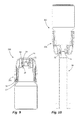
- FIGS. 14 to 17 show a further embodiment of a liquid dispenser 500 according to the invention with a discharge head according to the invention 501.
- This has a significant functional difference from the previous embodiments, since although also an outer member 50 and an inner member 20 are provided.
- the inner component 20 is formed by a specially adapted bottleneck 20b and an insert 20a fastened in a force-fit manner therein. This insert 20a has an end face 26 with apertures 27.
- the outer component 50 also consisting of two subcomponents, namely an outer member 50a and an insert 50b, in principle translationally movable.
- the outer component 50 is also the carrier of a pressure-dependent opening outlet valve 72.
- a switching valve 18 which is formed via an annular edge on the end face 26 and a cylindrical channel inlet on the insert 50b. In the state of Fig. 14 this switching valve 18 is closed. Opening of the switching valve 18 by displacement of the outer member 50 relative to the inner member 20 is not initially possible because abut stops 63 on the inside of the outer member 50 below a stop ring 44 of the inner member 20. Only by applying force to the actuating surfaces 64 in the direction of Fig.
- the stops 63 are deflected in the direction of arrows 4, so that then the outer member 50 can be raised. However, this movement is limited by stops 46, 53, so that the outer member 50 is in turn mounted captive on the inner member 20. As soon as the outer component 50 has been lifted, a liquid path 6 is again open, through which the liquid can reach the pressure-dependent opening outlet valve 72. If the outer component 50 is pressed down again after a discharge, the stops 63 automatically snap in again below the stop ring 44, so that again a child-resistant state is produced, which can only be overcome again by applying force to the actuating surfaces 64.
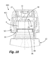
- the embodiment of the Fig. 18 shows a dispensing head 601 of a dispenser 600 which is substantially identical to the dispensing head 501 of the previous embodiment.
- the peculiarity lies in the fact that an aperture 96 is used, which partially blocks the inflow of liquid from the liquid reservoir in the direction of the outlet valve 72.
- 96 passage channels 98 are provided on the outside of the cup-shaped aperture, can pass through the liquid.
- the purpose of this aperture 96 is to make the discharge of liquid in the case of accidentally left open dispenser still difficult.
Landscapes
- Mechanical Engineering (AREA)
- Engineering & Computer Science (AREA)
- Health & Medical Sciences (AREA)
- Pharmacology & Pharmacy (AREA)
- General Physics & Mathematics (AREA)
- Fluid Mechanics (AREA)
- Physics & Mathematics (AREA)
- Life Sciences & Earth Sciences (AREA)
- Animal Behavior & Ethology (AREA)
- General Health & Medical Sciences (AREA)
- Public Health (AREA)
- Veterinary Medicine (AREA)
- Containers And Packaging Bodies Having A Special Means To Remove Contents (AREA)
- Closures For Containers (AREA)
Priority Applications (3)
| Application Number | Priority Date | Filing Date | Title |
|---|---|---|---|
| EP15182116.2A EP3135599B1 (fr) | 2015-08-24 | 2015-08-24 | Tete distributrice pour un distributeur de liquide et distributeur de liquide |
| US15/244,512 US10173815B2 (en) | 2015-08-24 | 2016-08-23 | Discharge head for a fluid dispenser and fluid dispenser |
| CN201610713060.7A CN106475247B (zh) | 2015-08-24 | 2016-08-24 | 用于流体分配器的排出头和流体分配器 |
Applications Claiming Priority (1)
| Application Number | Priority Date | Filing Date | Title |
|---|---|---|---|
| EP15182116.2A EP3135599B1 (fr) | 2015-08-24 | 2015-08-24 | Tete distributrice pour un distributeur de liquide et distributeur de liquide |
Publications (2)
| Publication Number | Publication Date |
|---|---|
| EP3135599A1 true EP3135599A1 (fr) | 2017-03-01 |
| EP3135599B1 EP3135599B1 (fr) | 2018-10-03 |
Family
ID=53969262
Family Applications (1)
| Application Number | Title | Priority Date | Filing Date |
|---|---|---|---|
| EP15182116.2A Active EP3135599B1 (fr) | 2015-08-24 | 2015-08-24 | Tete distributrice pour un distributeur de liquide et distributeur de liquide |
Country Status (3)
| Country | Link |
|---|---|
| US (1) | US10173815B2 (fr) |
| EP (1) | EP3135599B1 (fr) |
| CN (1) | CN106475247B (fr) |
Families Citing this family (13)
| Publication number | Priority date | Publication date | Assignee | Title |
|---|---|---|---|---|
| USD899194S1 (en) * | 2007-11-29 | 2020-10-20 | Automatic Bar Controls, Inc. | Dispensing apparatus |
| USD907500S1 (en) * | 2017-07-13 | 2021-01-12 | Chubby Gorilla, Inc. | Bottle |
| USD834950S1 (en) | 2016-08-06 | 2018-12-04 | Chubby Gorilla, Inc. | Dispensing bottle and cap in combination |
| USD826068S1 (en) | 2016-11-13 | 2018-08-21 | Eyad Aboabdo | Dispensing bottle kit |
| EP3323753B1 (fr) * | 2016-11-17 | 2019-08-07 | Aptar Radolfzell GmbH | Tête de distribution et distributeur de liquide comprenant une telle tête de distribution |
| DE102016222682B3 (de) * | 2016-11-17 | 2017-10-05 | Aptar Radolfzell Gmbh | Austragkopf für einen Flüssigkeitsspender und Flüssigkeitsspender mit einem solchen Austragkopf |
| CA179103S (en) | 2017-07-13 | 2019-06-12 | Chubby Gorilla Inc | Bottle |
| GB201803224D0 (en) * | 2018-02-27 | 2018-04-11 | Compgen Ltd | A container with child resistant means |
| USD1009638S1 (en) * | 2019-06-07 | 2024-01-02 | Seiko Epson Corporation | Packaging container |
| USD979418S1 (en) * | 2019-06-28 | 2023-02-28 | Seiko Epson Corporation | Packaging container |
| USD974548S1 (en) | 2020-01-13 | 2023-01-03 | The Procter & Gamble Company | Dose cup for liquid medicinal formulations |
| CN114945807A (zh) * | 2020-01-13 | 2022-08-26 | 宝洁公司 | 量杯和药物流体递送系统 |
| USD1012699S1 (en) | 2020-01-13 | 2024-01-30 | The Procter & Gamble Company | Dose cup for liquid medicinal formulations |
Citations (5)
| Publication number | Priority date | Publication date | Assignee | Title |
|---|---|---|---|---|
| US4544063A (en) * | 1984-10-05 | 1985-10-01 | Neward Lance M | Closure for receptacle |
| WO1998004471A1 (fr) * | 1996-07-31 | 1998-02-05 | Defi International | Capsule distributrice pour recipient a ouverture et fermeture par mouvement translatif |
| US20110163132A1 (en) * | 2009-12-02 | 2011-07-07 | Fabrice Moreau | Dispensing cap, container and method for dispensing contents |
| DE102013202933B3 (de) | 2013-02-22 | 2013-11-14 | Aptar Radolfzell Gmbh | Kindergesicherte Austragvorrichtung |
| DE102013107439A1 (de) * | 2013-07-13 | 2015-01-15 | Fuchs & Böhme Gmbh | Dosierbehälter und Dosiervorrichtung für pulverförmige Schüttgüter |
Family Cites Families (7)
| Publication number | Priority date | Publication date | Assignee | Title |
|---|---|---|---|---|
| US4506809A (en) * | 1982-06-25 | 1985-03-26 | Calmar, Inc. | Dispensing fitment for squeeze bottles |
| DE8235857U1 (de) * | 1982-12-21 | 1984-05-24 | Wella Ag, 6100 Darmstadt | Selbsttaetiger Verschluss fuer flexible Behaelter |
| US4785978A (en) * | 1987-03-02 | 1988-11-22 | Japan Crown Cork Co., Ltd. | Container closure provided with automatic opening-closing mechanism |
| GB9912977D0 (en) * | 1999-06-04 | 1999-08-04 | Crown Cork & Seal Tech Corp | Closure with dispensing valve |
| IT1310921B1 (it) * | 1999-06-24 | 2002-02-27 | Mrp Medical Res & Promotion Es | Flacone pluridose con beccuccio di dosaggio per liquidi,particolarmente prodotti farmaceutici. |
| US6446844B1 (en) * | 2001-12-18 | 2002-09-10 | Seaquist Closures Foreign, Inc. | Closure with internal flow control for a pressure openable valve in an extendable/retractable nozzle |
| CN201070482Y (zh) * | 2007-06-15 | 2008-06-11 | 林新平 | 温暖型一次性输液器 |
-
2015
- 2015-08-24 EP EP15182116.2A patent/EP3135599B1/fr active Active
-
2016
- 2016-08-23 US US15/244,512 patent/US10173815B2/en active Active
- 2016-08-24 CN CN201610713060.7A patent/CN106475247B/zh active Active
Patent Citations (5)
| Publication number | Priority date | Publication date | Assignee | Title |
|---|---|---|---|---|
| US4544063A (en) * | 1984-10-05 | 1985-10-01 | Neward Lance M | Closure for receptacle |
| WO1998004471A1 (fr) * | 1996-07-31 | 1998-02-05 | Defi International | Capsule distributrice pour recipient a ouverture et fermeture par mouvement translatif |
| US20110163132A1 (en) * | 2009-12-02 | 2011-07-07 | Fabrice Moreau | Dispensing cap, container and method for dispensing contents |
| DE102013202933B3 (de) | 2013-02-22 | 2013-11-14 | Aptar Radolfzell Gmbh | Kindergesicherte Austragvorrichtung |
| DE102013107439A1 (de) * | 2013-07-13 | 2015-01-15 | Fuchs & Böhme Gmbh | Dosierbehälter und Dosiervorrichtung für pulverförmige Schüttgüter |
Also Published As
| Publication number | Publication date |
|---|---|
| EP3135599B1 (fr) | 2018-10-03 |
| US20170057710A1 (en) | 2017-03-02 |
| CN106475247B (zh) | 2021-02-26 |
| US10173815B2 (en) | 2019-01-08 |
| CN106475247A (zh) | 2017-03-08 |
Similar Documents
| Publication | Publication Date | Title |
|---|---|---|
| EP3135599B1 (fr) | Tete distributrice pour un distributeur de liquide et distributeur de liquide | |
| EP0922499B1 (fr) | Distributeur de fluides | |
| DE69808559T2 (de) | Behälter für zur Benutzung aufzulösende Pulver oder Flüssigkeiten | |
| EP3075405B1 (fr) | Dispositif de distribution | |
| DE69206988T2 (de) | Vorrichtung zum Spritzen einer vorbestimmten Dosis eines Mediums und Verfahren zum Füllen dieser Vorrichtung | |
| EP3984652B1 (fr) | Distributeur de liquide | |
| WO2003026803A1 (fr) | Dispositif de dosage muni d'un systeme de pompage | |
| DE20107507U1 (de) | Ampulle zum Ausgeben einer Substanz oder eines aus mehreren Substanzen bestehenden Gemisches | |
| DE19942792A1 (de) | Spender für Medien | |
| DE69402026T2 (de) | Kunststoffschraubdeckel zur Abgabe von Flüssigkeiten | |
| EP3978389B1 (fr) | Distributeur de liquide, en particulier distributeur de gouttes | |
| EP1682374B1 (fr) | Couvercle de fermeture pour tubulure de remplissage d'un recipient et tubulure de remplissage correspondante | |
| EP0953515A2 (fr) | Distributeur de fluide | |
| DE102013202933B3 (de) | Kindergesicherte Austragvorrichtung | |
| EP1295645B1 (fr) | Dispositif de dosage muni d'une pompe | |
| DE3834091C2 (fr) | ||
| WO2022023468A1 (fr) | Réservoir de fluide pour pistolet de pulvérisation à dispositif de ventilation | |
| EP0187314A2 (fr) | Tête de distribution pour pulvérisateur | |
| DE202007008646U1 (de) | Ventil | |
| WO2007017036A1 (fr) | Bouchon securite enfant destine a des recipients, en particulier des bouteilles en plastique | |
| DE19652148C2 (de) | Behälter, insbesondere Flasche | |
| DE9300042U1 (de) | Gewindeteil aus Kunststoff zum Aufsetzen auf einen Tubenhals | |
| CH634790A5 (de) | Verschlussvorrichtung fuer eine auslassoeffnung, z.b. fuer tuben oder flaschen. | |
| EP1706611B1 (fr) | Dispositif d'antidevissage destine a un contenant | |
| EP2468655B1 (fr) | Flacon distributeur |
Legal Events
| Date | Code | Title | Description |
|---|---|---|---|
| PUAI | Public reference made under article 153(3) epc to a published international application that has entered the european phase |
Free format text: ORIGINAL CODE: 0009012 |
|
| STAA | Information on the status of an ep patent application or granted ep patent |
Free format text: STATUS: THE APPLICATION HAS BEEN PUBLISHED |
|
| AK | Designated contracting states |
Kind code of ref document: A1 Designated state(s): AL AT BE BG CH CY CZ DE DK EE ES FI FR GB GR HR HU IE IS IT LI LT LU LV MC MK MT NL NO PL PT RO RS SE SI SK SM TR |
|
| AX | Request for extension of the european patent |
Extension state: BA ME |
|
| STAA | Information on the status of an ep patent application or granted ep patent |
Free format text: STATUS: REQUEST FOR EXAMINATION WAS MADE |
|
| 17P | Request for examination filed |
Effective date: 20170811 |
|
| RBV | Designated contracting states (corrected) |
Designated state(s): AL AT BE BG CH CY CZ DE DK EE ES FI FR GB GR HR HU IE IS IT LI LT LU LV MC MK MT NL NO PL PT RO RS SE SI SK SM TR |
|
| GRAP | Despatch of communication of intention to grant a patent |
Free format text: ORIGINAL CODE: EPIDOSNIGR1 |
|
| STAA | Information on the status of an ep patent application or granted ep patent |
Free format text: STATUS: GRANT OF PATENT IS INTENDED |
|
| INTG | Intention to grant announced |
Effective date: 20180503 |
|
| GRAS | Grant fee paid |
Free format text: ORIGINAL CODE: EPIDOSNIGR3 |
|
| GRAA | (expected) grant |
Free format text: ORIGINAL CODE: 0009210 |
|
| STAA | Information on the status of an ep patent application or granted ep patent |
Free format text: STATUS: THE PATENT HAS BEEN GRANTED |
|
| AK | Designated contracting states |
Kind code of ref document: B1 Designated state(s): AL AT BE BG CH CY CZ DE DK EE ES FI FR GB GR HR HU IE IS IT LI LT LU LV MC MK MT NL NO PL PT RO RS SE SI SK SM TR |
|
| REG | Reference to a national code |
Ref country code: GB Ref legal event code: FG4D Free format text: NOT ENGLISH |
|
| REG | Reference to a national code |
Ref country code: CH Ref legal event code: EP Ref country code: AT Ref legal event code: REF Ref document number: 1048346 Country of ref document: AT Kind code of ref document: T Effective date: 20181015 |
|
| REG | Reference to a national code |
Ref country code: IE Ref legal event code: FG4D Free format text: LANGUAGE OF EP DOCUMENT: GERMAN Ref country code: DE Ref legal event code: R096 Ref document number: 502015006204 Country of ref document: DE |
|
| REG | Reference to a national code |
Ref country code: CH Ref legal event code: NV Representative=s name: DR. LUSUARDI AG, CH |
|
| REG | Reference to a national code |
Ref country code: NL Ref legal event code: MP Effective date: 20181003 |
|
| REG | Reference to a national code |
Ref country code: LT Ref legal event code: MG4D |
|
| PG25 | Lapsed in a contracting state [announced via postgrant information from national office to epo] |
Ref country code: NL Free format text: LAPSE BECAUSE OF FAILURE TO SUBMIT A TRANSLATION OF THE DESCRIPTION OR TO PAY THE FEE WITHIN THE PRESCRIBED TIME-LIMIT Effective date: 20181003 |
|
| PG25 | Lapsed in a contracting state [announced via postgrant information from national office to epo] |
Ref country code: ES Free format text: LAPSE BECAUSE OF FAILURE TO SUBMIT A TRANSLATION OF THE DESCRIPTION OR TO PAY THE FEE WITHIN THE PRESCRIBED TIME-LIMIT Effective date: 20181003 Ref country code: CZ Free format text: LAPSE BECAUSE OF FAILURE TO SUBMIT A TRANSLATION OF THE DESCRIPTION OR TO PAY THE FEE WITHIN THE PRESCRIBED TIME-LIMIT Effective date: 20181003 Ref country code: IS Free format text: LAPSE BECAUSE OF FAILURE TO SUBMIT A TRANSLATION OF THE DESCRIPTION OR TO PAY THE FEE WITHIN THE PRESCRIBED TIME-LIMIT Effective date: 20190203 Ref country code: BG Free format text: LAPSE BECAUSE OF FAILURE TO SUBMIT A TRANSLATION OF THE DESCRIPTION OR TO PAY THE FEE WITHIN THE PRESCRIBED TIME-LIMIT Effective date: 20190103 Ref country code: NO Free format text: LAPSE BECAUSE OF FAILURE TO SUBMIT A TRANSLATION OF THE DESCRIPTION OR TO PAY THE FEE WITHIN THE PRESCRIBED TIME-LIMIT Effective date: 20190103 Ref country code: LT Free format text: LAPSE BECAUSE OF FAILURE TO SUBMIT A TRANSLATION OF THE DESCRIPTION OR TO PAY THE FEE WITHIN THE PRESCRIBED TIME-LIMIT Effective date: 20181003 Ref country code: FI Free format text: LAPSE BECAUSE OF FAILURE TO SUBMIT A TRANSLATION OF THE DESCRIPTION OR TO PAY THE FEE WITHIN THE PRESCRIBED TIME-LIMIT Effective date: 20181003 Ref country code: LV Free format text: LAPSE BECAUSE OF FAILURE TO SUBMIT A TRANSLATION OF THE DESCRIPTION OR TO PAY THE FEE WITHIN THE PRESCRIBED TIME-LIMIT Effective date: 20181003 Ref country code: HR Free format text: LAPSE BECAUSE OF FAILURE TO SUBMIT A TRANSLATION OF THE DESCRIPTION OR TO PAY THE FEE WITHIN THE PRESCRIBED TIME-LIMIT Effective date: 20181003 Ref country code: PL Free format text: LAPSE BECAUSE OF FAILURE TO SUBMIT A TRANSLATION OF THE DESCRIPTION OR TO PAY THE FEE WITHIN THE PRESCRIBED TIME-LIMIT Effective date: 20181003 |
|
| PG25 | Lapsed in a contracting state [announced via postgrant information from national office to epo] |
Ref country code: SE Free format text: LAPSE BECAUSE OF FAILURE TO SUBMIT A TRANSLATION OF THE DESCRIPTION OR TO PAY THE FEE WITHIN THE PRESCRIBED TIME-LIMIT Effective date: 20181003 Ref country code: RS Free format text: LAPSE BECAUSE OF FAILURE TO SUBMIT A TRANSLATION OF THE DESCRIPTION OR TO PAY THE FEE WITHIN THE PRESCRIBED TIME-LIMIT Effective date: 20181003 Ref country code: AL Free format text: LAPSE BECAUSE OF FAILURE TO SUBMIT A TRANSLATION OF THE DESCRIPTION OR TO PAY THE FEE WITHIN THE PRESCRIBED TIME-LIMIT Effective date: 20181003 Ref country code: PT Free format text: LAPSE BECAUSE OF FAILURE TO SUBMIT A TRANSLATION OF THE DESCRIPTION OR TO PAY THE FEE WITHIN THE PRESCRIBED TIME-LIMIT Effective date: 20190203 Ref country code: GR Free format text: LAPSE BECAUSE OF FAILURE TO SUBMIT A TRANSLATION OF THE DESCRIPTION OR TO PAY THE FEE WITHIN THE PRESCRIBED TIME-LIMIT Effective date: 20190104 |
|
| REG | Reference to a national code |
Ref country code: DE Ref legal event code: R097 Ref document number: 502015006204 Country of ref document: DE |
|
| PG25 | Lapsed in a contracting state [announced via postgrant information from national office to epo] |
Ref country code: DK Free format text: LAPSE BECAUSE OF FAILURE TO SUBMIT A TRANSLATION OF THE DESCRIPTION OR TO PAY THE FEE WITHIN THE PRESCRIBED TIME-LIMIT Effective date: 20181003 |
|
| PLBE | No opposition filed within time limit |
Free format text: ORIGINAL CODE: 0009261 |
|
| STAA | Information on the status of an ep patent application or granted ep patent |
Free format text: STATUS: NO OPPOSITION FILED WITHIN TIME LIMIT |
|
| PG25 | Lapsed in a contracting state [announced via postgrant information from national office to epo] |
Ref country code: RO Free format text: LAPSE BECAUSE OF FAILURE TO SUBMIT A TRANSLATION OF THE DESCRIPTION OR TO PAY THE FEE WITHIN THE PRESCRIBED TIME-LIMIT Effective date: 20181003 Ref country code: SM Free format text: LAPSE BECAUSE OF FAILURE TO SUBMIT A TRANSLATION OF THE DESCRIPTION OR TO PAY THE FEE WITHIN THE PRESCRIBED TIME-LIMIT Effective date: 20181003 Ref country code: EE Free format text: LAPSE BECAUSE OF FAILURE TO SUBMIT A TRANSLATION OF THE DESCRIPTION OR TO PAY THE FEE WITHIN THE PRESCRIBED TIME-LIMIT Effective date: 20181003 Ref country code: SK Free format text: LAPSE BECAUSE OF FAILURE TO SUBMIT A TRANSLATION OF THE DESCRIPTION OR TO PAY THE FEE WITHIN THE PRESCRIBED TIME-LIMIT Effective date: 20181003 |
|
| 26N | No opposition filed |
Effective date: 20190704 |
|
| PG25 | Lapsed in a contracting state [announced via postgrant information from national office to epo] |
Ref country code: SI Free format text: LAPSE BECAUSE OF FAILURE TO SUBMIT A TRANSLATION OF THE DESCRIPTION OR TO PAY THE FEE WITHIN THE PRESCRIBED TIME-LIMIT Effective date: 20181003 |
|
| PG25 | Lapsed in a contracting state [announced via postgrant information from national office to epo] |
Ref country code: TR Free format text: LAPSE BECAUSE OF FAILURE TO SUBMIT A TRANSLATION OF THE DESCRIPTION OR TO PAY THE FEE WITHIN THE PRESCRIBED TIME-LIMIT Effective date: 20181003 |
|
| PG25 | Lapsed in a contracting state [announced via postgrant information from national office to epo] |
Ref country code: LU Free format text: LAPSE BECAUSE OF NON-PAYMENT OF DUE FEES Effective date: 20190824 Ref country code: MC Free format text: LAPSE BECAUSE OF FAILURE TO SUBMIT A TRANSLATION OF THE DESCRIPTION OR TO PAY THE FEE WITHIN THE PRESCRIBED TIME-LIMIT Effective date: 20181003 |
|
| REG | Reference to a national code |
Ref country code: BE Ref legal event code: MM Effective date: 20190831 |
|
| PG25 | Lapsed in a contracting state [announced via postgrant information from national office to epo] |
Ref country code: IE Free format text: LAPSE BECAUSE OF NON-PAYMENT OF DUE FEES Effective date: 20190824 |
|
| PG25 | Lapsed in a contracting state [announced via postgrant information from national office to epo] |
Ref country code: BE Free format text: LAPSE BECAUSE OF NON-PAYMENT OF DUE FEES Effective date: 20190831 |
|
| PG25 | Lapsed in a contracting state [announced via postgrant information from national office to epo] |
Ref country code: CY Free format text: LAPSE BECAUSE OF FAILURE TO SUBMIT A TRANSLATION OF THE DESCRIPTION OR TO PAY THE FEE WITHIN THE PRESCRIBED TIME-LIMIT Effective date: 20181003 |
|
| PG25 | Lapsed in a contracting state [announced via postgrant information from national office to epo] |
Ref country code: MT Free format text: LAPSE BECAUSE OF FAILURE TO SUBMIT A TRANSLATION OF THE DESCRIPTION OR TO PAY THE FEE WITHIN THE PRESCRIBED TIME-LIMIT Effective date: 20181003 Ref country code: HU Free format text: LAPSE BECAUSE OF FAILURE TO SUBMIT A TRANSLATION OF THE DESCRIPTION OR TO PAY THE FEE WITHIN THE PRESCRIBED TIME-LIMIT; INVALID AB INITIO Effective date: 20150824 |
|
| REG | Reference to a national code |
Ref country code: AT Ref legal event code: MM01 Ref document number: 1048346 Country of ref document: AT Kind code of ref document: T Effective date: 20200824 |
|
| PG25 | Lapsed in a contracting state [announced via postgrant information from national office to epo] |
Ref country code: AT Free format text: LAPSE BECAUSE OF NON-PAYMENT OF DUE FEES Effective date: 20200824 |
|
| REG | Reference to a national code |
Ref country code: DE Ref legal event code: R082 Ref document number: 502015006204 Country of ref document: DE Representative=s name: WITTE, WELLER & PARTNER PATENTANWAELTE MBB, DE |
|
| PG25 | Lapsed in a contracting state [announced via postgrant information from national office to epo] |
Ref country code: MK Free format text: LAPSE BECAUSE OF FAILURE TO SUBMIT A TRANSLATION OF THE DESCRIPTION OR TO PAY THE FEE WITHIN THE PRESCRIBED TIME-LIMIT Effective date: 20181003 |
|
| P01 | Opt-out of the competence of the unified patent court (upc) registered |
Effective date: 20230502 |
|
| PGFP | Annual fee paid to national office [announced via postgrant information from national office to epo] |
Ref country code: IT Payment date: 20230831 Year of fee payment: 9 Ref country code: GB Payment date: 20230824 Year of fee payment: 9 Ref country code: CH Payment date: 20230902 Year of fee payment: 9 |
|
| PGFP | Annual fee paid to national office [announced via postgrant information from national office to epo] |
Ref country code: FR Payment date: 20230821 Year of fee payment: 9 Ref country code: DE Payment date: 20230823 Year of fee payment: 9 |