EP3133380B1 - Photodetector output correction method used for spectroscopic analyzer or spectroscope, spectroscopic analyzer or spectroscope using this method and program for spectroscopic analyzer or spectroscope instructing this method - Google Patents
Photodetector output correction method used for spectroscopic analyzer or spectroscope, spectroscopic analyzer or spectroscope using this method and program for spectroscopic analyzer or spectroscope instructing this method Download PDFInfo
- Publication number
- EP3133380B1 EP3133380B1 EP16180886.0A EP16180886A EP3133380B1 EP 3133380 B1 EP3133380 B1 EP 3133380B1 EP 16180886 A EP16180886 A EP 16180886A EP 3133380 B1 EP3133380 B1 EP 3133380B1
- Authority
- EP
- European Patent Office
- Prior art keywords
- output value
- photodetector
- light beams
- wavenumber
- optical element
- Prior art date
- Legal status (The legal status is an assumption and is not a legal conclusion. Google has not performed a legal analysis and makes no representation as to the accuracy of the status listed.)
- Active
Links
Images



Classifications
-
- G—PHYSICS
- G01—MEASURING; TESTING
- G01J—MEASUREMENT OF INTENSITY, VELOCITY, SPECTRAL CONTENT, POLARISATION, PHASE OR PULSE CHARACTERISTICS OF INFRARED, VISIBLE OR ULTRAVIOLET LIGHT; COLORIMETRY; RADIATION PYROMETRY
- G01J3/00—Spectrometry; Spectrophotometry; Monochromators; Measuring colours
- G01J3/28—Investigating the spectrum
-
- G—PHYSICS
- G01—MEASURING; TESTING
- G01J—MEASUREMENT OF INTENSITY, VELOCITY, SPECTRAL CONTENT, POLARISATION, PHASE OR PULSE CHARACTERISTICS OF INFRARED, VISIBLE OR ULTRAVIOLET LIGHT; COLORIMETRY; RADIATION PYROMETRY
- G01J3/00—Spectrometry; Spectrophotometry; Monochromators; Measuring colours
- G01J3/02—Details
- G01J3/0297—Constructional arrangements for removing other types of optical noise or for performing calibration
-
- G—PHYSICS
- G01—MEASURING; TESTING
- G01J—MEASUREMENT OF INTENSITY, VELOCITY, SPECTRAL CONTENT, POLARISATION, PHASE OR PULSE CHARACTERISTICS OF INFRARED, VISIBLE OR ULTRAVIOLET LIGHT; COLORIMETRY; RADIATION PYROMETRY
- G01J3/00—Spectrometry; Spectrophotometry; Monochromators; Measuring colours
- G01J3/28—Investigating the spectrum
- G01J3/42—Absorption spectrometry; Double beam spectrometry; Flicker spectrometry; Reflection spectrometry
-
- G—PHYSICS
- G01—MEASURING; TESTING
- G01J—MEASUREMENT OF INTENSITY, VELOCITY, SPECTRAL CONTENT, POLARISATION, PHASE OR PULSE CHARACTERISTICS OF INFRARED, VISIBLE OR ULTRAVIOLET LIGHT; COLORIMETRY; RADIATION PYROMETRY
- G01J3/00—Spectrometry; Spectrophotometry; Monochromators; Measuring colours
- G01J3/12—Generating the spectrum; Monochromators
-
- G—PHYSICS
- G01—MEASURING; TESTING
- G01J—MEASUREMENT OF INTENSITY, VELOCITY, SPECTRAL CONTENT, POLARISATION, PHASE OR PULSE CHARACTERISTICS OF INFRARED, VISIBLE OR ULTRAVIOLET LIGHT; COLORIMETRY; RADIATION PYROMETRY
- G01J3/00—Spectrometry; Spectrophotometry; Monochromators; Measuring colours
- G01J3/28—Investigating the spectrum
- G01J3/45—Interferometric spectrometry
-
- G—PHYSICS
- G01—MEASURING; TESTING
- G01J—MEASUREMENT OF INTENSITY, VELOCITY, SPECTRAL CONTENT, POLARISATION, PHASE OR PULSE CHARACTERISTICS OF INFRARED, VISIBLE OR ULTRAVIOLET LIGHT; COLORIMETRY; RADIATION PYROMETRY
- G01J3/00—Spectrometry; Spectrophotometry; Monochromators; Measuring colours
- G01J3/28—Investigating the spectrum
- G01J3/45—Interferometric spectrometry
- G01J3/453—Interferometric spectrometry by correlation of the amplitudes
-
- G—PHYSICS
- G01—MEASURING; TESTING
- G01N—INVESTIGATING OR ANALYSING MATERIALS BY DETERMINING THEIR CHEMICAL OR PHYSICAL PROPERTIES
- G01N21/00—Investigating or analysing materials by the use of optical means, i.e. using sub-millimetre waves, infrared, visible or ultraviolet light
- G01N21/01—Arrangements or apparatus for facilitating the optical investigation
-
- G—PHYSICS
- G01—MEASURING; TESTING
- G01N—INVESTIGATING OR ANALYSING MATERIALS BY DETERMINING THEIR CHEMICAL OR PHYSICAL PROPERTIES
- G01N21/00—Investigating or analysing materials by the use of optical means, i.e. using sub-millimetre waves, infrared, visible or ultraviolet light
- G01N21/17—Systems in which incident light is modified in accordance with the properties of the material investigated
- G01N21/25—Colour; Spectral properties, i.e. comparison of effect of material on the light at two or more different wavelengths or wavelength bands
- G01N21/31—Investigating relative effect of material at wavelengths characteristic of specific elements or molecules, e.g. atomic absorption spectrometry
- G01N21/35—Investigating relative effect of material at wavelengths characteristic of specific elements or molecules, e.g. atomic absorption spectrometry using infrared light
- G01N21/3504—Investigating relative effect of material at wavelengths characteristic of specific elements or molecules, e.g. atomic absorption spectrometry using infrared light for analysing gases, e.g. multi-gas analysis
-
- G—PHYSICS
- G01—MEASURING; TESTING
- G01J—MEASUREMENT OF INTENSITY, VELOCITY, SPECTRAL CONTENT, POLARISATION, PHASE OR PULSE CHARACTERISTICS OF INFRARED, VISIBLE OR ULTRAVIOLET LIGHT; COLORIMETRY; RADIATION PYROMETRY
- G01J3/00—Spectrometry; Spectrophotometry; Monochromators; Measuring colours
- G01J3/12—Generating the spectrum; Monochromators
- G01J2003/1213—Filters in general, e.g. dichroic, band
-
- G—PHYSICS
- G01—MEASURING; TESTING
- G01J—MEASUREMENT OF INTENSITY, VELOCITY, SPECTRAL CONTENT, POLARISATION, PHASE OR PULSE CHARACTERISTICS OF INFRARED, VISIBLE OR ULTRAVIOLET LIGHT; COLORIMETRY; RADIATION PYROMETRY
- G01J3/00—Spectrometry; Spectrophotometry; Monochromators; Measuring colours
- G01J3/28—Investigating the spectrum
- G01J2003/2866—Markers; Calibrating of scan
- G01J2003/2876—Correcting linearity of signal
-
- G—PHYSICS
- G01—MEASURING; TESTING
- G01N—INVESTIGATING OR ANALYSING MATERIALS BY DETERMINING THEIR CHEMICAL OR PHYSICAL PROPERTIES
- G01N21/00—Investigating or analysing materials by the use of optical means, i.e. using sub-millimetre waves, infrared, visible or ultraviolet light
- G01N21/17—Systems in which incident light is modified in accordance with the properties of the material investigated
- G01N21/25—Colour; Spectral properties, i.e. comparison of effect of material on the light at two or more different wavelengths or wavelength bands
- G01N21/31—Investigating relative effect of material at wavelengths characteristic of specific elements or molecules, e.g. atomic absorption spectrometry
- G01N21/35—Investigating relative effect of material at wavelengths characteristic of specific elements or molecules, e.g. atomic absorption spectrometry using infrared light
- G01N2021/3595—Investigating relative effect of material at wavelengths characteristic of specific elements or molecules, e.g. atomic absorption spectrometry using infrared light using FTIR
-
- G—PHYSICS
- G01—MEASURING; TESTING
- G01N—INVESTIGATING OR ANALYSING MATERIALS BY DETERMINING THEIR CHEMICAL OR PHYSICAL PROPERTIES
- G01N2201/00—Features of devices classified in G01N21/00
- G01N2201/06—Illumination; Optics
- G01N2201/068—Optics, miscellaneous
-
- G—PHYSICS
- G01—MEASURING; TESTING
- G01N—INVESTIGATING OR ANALYSING MATERIALS BY DETERMINING THEIR CHEMICAL OR PHYSICAL PROPERTIES
- G01N2201/00—Features of devices classified in G01N21/00
- G01N2201/12—Circuits of general importance; Signal processing
- G01N2201/127—Calibration; base line adjustment; drift compensation
- G01N2201/12746—Calibration values determination
-
- G—PHYSICS
- G01—MEASURING; TESTING
- G01N—INVESTIGATING OR ANALYSING MATERIALS BY DETERMINING THEIR CHEMICAL OR PHYSICAL PROPERTIES
- G01N2201/00—Features of devices classified in G01N21/00
- G01N2201/12—Circuits of general importance; Signal processing
- G01N2201/127—Calibration; base line adjustment; drift compensation
- G01N2201/12746—Calibration values determination
- G01N2201/12784—Base line obtained from computation, histogram
Definitions
- the present invention relates to a photodetector output correction method used for a spectroscopic analyzer such as an FTIR or a spectroscope, and the like.
- a spectroscopic analyzer such as an FTIR analyzes sample components on the basis of a wavenumber intensity distribution (optical spectrum) of light beams passing through a sample.
- a photodetector such as a MCT photodetector is used.
- a calibration curve has been prepared by making predetermined reference light beams enter a photodetector to obtain the output value of the photodetector.
- Patent Literature 1 JPA-11-23367 US 2002/0110376 A1 relates to a method and an apparatus for calibrating a sensor for highlights.
- the sensor is calibrated by changing the intensity of the impinging light mainly in an intensity range where the output is a nonlinear fuction of the intensity.
- the paper by M.C. Abrams, G.C. Toon, and R.A. Schindler having the title "Practical example of the correction of Fourier-transform spectra for detector nonlinearity" and published in Applied Optics, 20 September 1994, (1994-09-20), pages 6307-6314, XP055327940, DOI; 10.1364/AO.33.006307 as well as the paper by P. Jeseck et al.
- Detector nonlinearity correction scheme for the LPMA balloonborne Fourier transform spectrometer and published in Applied Optics, vol. 37. No. 27, 20 September 1998 (1998-09-20), page 6544-6549, XP055327943, ISSN: 0003-6935, DOI: 10.1364/AO.37.006544 both deal with photoconductive detectors that display a nonlinear response when illuminated.
- JP 2015 087108 A a Fourier transformation spectrophotometer is equipped with a light quantity attenuation mechanism for attenuating and adjusting the light quantity getting into a detection unit.
- US 6 147 762 A discloses a correction method for a Fourier spectrometer synthesizing a distortion-free spectrum from a measured spectrum.
- the present invention is made in order to solve the above-described problems at once.
- the principal purpose is that it becomes possible to correct the output of a photodetector (prepare a calibration curve for the photodetector) used for a spectroscopic analyzer or a spectroscope in a short period of time with a simple configuration.
- a photodetector output calculation method is one used for a spectroscopic analyzer or a spectroscope including a light source, an interferometer splitting and then synthesizing light beams emitted from the light source, and a photodetector for measuring the intensity of the light beams exiting from the interferometer, wherein the photodetector is adapted such that the relationship between incident light intensity and an output value is substantially linear within a predetermined intensity range, and the photodetector output calculation method includes:
- the arithmetic expression refers to not only an expression for calculating the intensity of incident light beams from the output value of the photodetector but also a concept including a map, a lookup table, and the like, and may be reworded as a calibration curve.
- a wavenumber is assumed to also include a wavelength that is the reciprocal of the wavenumber.
- the value of the following expression 1 comprises a value indicating the wavenumber transmission characteristic or wavenumber reflection characteristic of the optical element F given in (k) it can be exemplified as a range.
- Y 1 k / C y ⁇ Y 2 k where k represents a wavenumber, Y 1 (k) represents the first output value, Y 2 (k) represents the second output value, F(k) represents the wavenumber transmission characteristic or the wavenumber reflection characteristic of the optical element, y represents the output value of the photodetector, and C(y) represents the arithmetic expression.
- a spectroscopic analyzer or a spectroscope includes a light source, an interferometer splitting and then synthesizing light beams emitted from the light source, and a photodetector that detects light beams exiting from the interferometer, wherein the photodetector is adapted such that the relationship between incident light intensity and an output value is substantially linear within a predetermined intensity range, and the spectroscopic analyzer or the spectroscope further includes:
- the mechanism is a supporting mechanism that selectively moves the optical element to any of a first position where the optical element is positioned in an optical path from the light source to the photodetector and a second position where the optical element is withdrawn from the optical path.
- a band-pass filter As a preferable optical element for making the incident light intensity fall within the predetermined range, a band-pass filter can be cited.
- the arithmetic expression for calculating the intensity of incident light beams from the output value of the photodetector can be obtained.
- a photodetector output correction expression used for the spectroscopic analyzer i.e., the arithmetic expression can be prepared in a short period of time with a simple configuration.
- a spectroscopic analyzer 100 according to one embodiment of the present invention will hereinafter be described with reference to drawings.
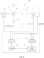
- the spectroscopic analyzer 100 of the present embodiment is a Fourier transform infrared spectroscopic analyzer 100 referred to as a so-called FTIR. And, it includes a light source 1, an interferometer (spectroscopic part) 2, a sample setting part 3, a photodetector 4, and an arithmetic processing unit 5, as illustrated in FIG. 2 .
- the light source 1 is one that emits light beams having a broad spectrum (continuous light including light of a number of wavenumbers).
- a broad spectrum continuous light including light of a number of wavenumbers.
- it is a tungsten iodine lamp or a high intensity ceramic light source is used.
- the interferometer 2 is using a so-called Michelson interferometer. It is included a half-mirror (beam splitter) 21, a fixed mirror 22, and a moving mirror 23.
- the light beams entering the interferometer 2 from the light source 1 is divided into reflected light beams and transmitted light beams by the half-mirror 21.
- One of the light beams is reflected by the fixed mirror 22, and the other one is reflected by the moving mirror 23.
- Both of the reflected light beams return to the half-mirror 21 again and are synthesized, and the synthesized light beams are emitted from the interferometer 2.
- the sample setting part 3 is herein a cell into which gas (hereinafter also referred to as a sample) as a measuring target is introduced. And, it adapted such that the light beams exiting from the interferometer 2 transmits through the sample inside the sample setting part 3, and is then guided to the photodetector 4.
- gas hereinafter also referred to as a sample
- the photodetector 4 is herein a detector referred to as a so-called MCT photodetector 4.
- the arithmetic processing unit 5 is one having: an analog electric circuit having some devices such as a buffer and an amplifier; a digital electric circuit having some devices such as a CPU, a memory, and a DSP; and an A/D converter and the like interposing therebetween.
- the CPU and its peripheral devices cooperate in accordance with a predetermined program stored in the memory.
- the arithmetic processing unit 5 functions as an analysis part 51 that calculates a spectrum of the light beams (an optical spectrum) having transmitted through the sample from the output values of the photodetector 4 as well as obtaining light absorbances at respective wavenumbers from the optical spectrum to analyze the sample.
- the analysis part 51 calculates the optical spectrum in the following manner.
- the light intensity draws a sine curve by interference, if a horizontal axis as the position of the moving mirror 23.
- the sine curve varies depending on a wavenumber.
- the intensity of the actual light beams is represented by the superposition of sine curves drawn at respective wavenumbers, and an interference pattern (interferogram) has a wave packet shape.
- the analysis part 51 obtains the position of the moving mirror 23 used a range finder (not illustrated) such as a HeNe laser. And, it obtains the light intensities corresponding to the respective positions of the moving mirror 23 using the photodetector 4. And, it performs a fast Fourier transform (FFT) on the interference pattern obtained from the light intensities and the respective positions to thereby convert to the optical spectrum with respective wavenumber components used as a horizontal axis.
- FFT fast Fourier transform
- the intensity of the light beams having transmitted through the sample i.e., the intensity of the light beams entering the photodetector 4 is calculated on the basis of the output value of the photodetector 4.
- the relationship (calibration curve) between the output value of the photodetector 4 and the incident light intensity to store it in the memory.
- the calibration curve in this embodiment is an arithmetic expression for converting the output value of the photodetector 4 into the incident light intensity, but may be a table or a map.
- the following mechanism is provided in the spectroscopic analyzer 100.
- an optical filter 6 as an optical element is removably inserted.
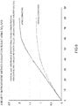
- the optical filter 6 is a flat plate-shaped one, and herein a so-called band-pass filter. And, it has a wavenumber transmission characteristics that is exemplified as illustrated in FIG. 3 .
- the optical filter 6 is movably supported by a filter supporting member 7 that shapes plate-like. And, it is mounted to a housing slidably.
- a filter supporting member 7 In the filter supporting member 7, two light transmission holes 7a and 7b are provided. And, the optical filter 6 is attached on the filter supporting member 7 so as to cover the first light transmission hole 7a.
- the optical filter 6 can be selectively positioned in any of a first position where the first light transmission hole 7a, i.e., the optical filter 6 is positioned in the optical path (see FIG. 4(a) ), a second position where the second light transmission hole 7b is positioned in the optical path (see FIG. 4(b) ), and a third position where the optical path is blocked by the filter supporting member 7 (see FIG. 4(c) ).
- the arithmetic processing unit 5 further includes an output value acquisition part 52 and an arithmetic expression calculation part 53.
- the output value acquisition part 52 is one that acquires the first output value as the output value of the photodetector 4 at each wavenumber when the light beams exiting from the sample setting part 3 passes through the optical filter 6 and then enters the photodetector 4. And, it acquires the second output value as the output value of the photodetector 4 at each wavenumber when the light beams exiting from the sample setting part 3 directly enters the photodetector 4 without transmitting through the optical filter 6. And, it stores the first and second output values in a data storage part 54 provided in a predetermined area of the memory.
- the output value acquisition part 52 is also herein adapted to acquire the output value of the photodetector 4 as the third output value when the light beams exiting from the sample setting part 3 is blocked.
- the arithmetic expression calculation part 53 is one that uses the wavenumber transmission characteristics of the optical filter 6 preliminarily stored in the data storage part 54 as a parameter, in addition to the first and second output values, and obtains the arithmetic expression for converting the output value of the photodetector 4 into the incident light intensity. And, it stores the arithmetic expression in the data storage part 54.
- the sample setting part 3 is filled with the sample which states such as temperature, component concentration, and pressure, are kept constant.
- states such as temperature, component concentration, and pressure
- the reason to keep the states constant is to prevent that the spectrum of the light transmitting through the sample from being changed during the calculation of the arithmetic expression. At this time, it is desirable to minimize the overlap between wavenumber of infrared light absorption and transmission of the optical filter.
- the sample may be, for example, nitrogen gas or air.
- the sample is not sealed but may be under vacuum.
- the filter supporting member 7 moves to the first position to arrange the optical filter 6 in the optical path.
- the output value acquisition part 52 senses the start of the first arithmetic operation, and receive and acquire the output values (interferogram) of the photodetector 4 corresponding to the respective positions of the moving mirror 23.
- the output value acquisition part 52 corrects the offset of the interferogram by subtracting the output values of the photodetector 4 when the filter supporting member 7 is in the third position and the light beams to enter the photodetector 4 is blocked.
- the output value acquisition part 52 performs a fast Fourier transform of the interferogram that corrected offset, and calculates the first output value Y1(k) as the output value of the photodetector 4 at each wavenumber. And, it stores the first output value Y1(k) in the data storage part 54, and ends an action. Note that k represents a wavenumber.
- the operator moves the filter supporting member 7 to the second position to withdraw the optical filter 6 from the optical path.
- the output value acquisition part 52 senses the start of the second arithmetic operation, and acquires the output values (interferogram) of the photodetector 4 corresponding to the respective positions of the moving mirror 23.
- the output value acquisition part 52 corrects the offset of the interferogram by subtracting the output values of the photodetector 4 when the filter supporting member 7 is in the third position and the light beams to enter the photodetector 4 is blocked.
- the output value acquisition part 52 performs a fast Fourier transform of the interferogram that corrected offset, and calculates the second output value Y 2 (k) as the output value of the photodetector 4 at each wavenumber. And, it stores the second output value Y 2 (k) in the data storage part 54, and ends an action.
- FIG. 5 illustrates an example of the interferograms obtained when the filter supporting member 7 is in the first position (with the optical filter), the second position (without optical filter), and the third position (light beams are blocked).
- the arithmetic expression calculation part 53 acquires the first and second output values Y 1 (k) and Y 2 (k) at predetermined multiple wavenumbers (here, for example, at 15 points, i.e., P1 to P15 in FIG. 3 ) from the data storage part 54. And, it obtains the arithmetic expression C(y) which meeting the following evaluation function using an optimization method, for example.
- F(k) represents the transmittance of the optical filter 6 at each wavenumber (filter characteristics), and y represents the output value of the photodetector 4.
- C(y) represents an expression which uses y as a variable and of which the form is predetermined except for the coefficients of the variable. It is expressed, for example, by the following Expression (3).
- C y C 1 ⁇ y + C 2 ⁇ y 2 + C 3 ⁇ y 3 ...
- the arithmetic expression calculation part 53 obtains the coefficients C 1 to C 3 using the known optimization method. The optimization is performed such that the value of the left-hand side of Expression 2 falls within a predetermined range around the F(k) value of the right-hand side. In addition, the arithmetic expression C(y) obtained in this manner is stored in the data storage part 54.
- the analysis part 51 corrects the output values y (interferogram) of the photodetector 4 corresponding to the respective positions of the moving mirror 23 using the arithmetic expression C(y) stored in the data storage part 54. Specifically, the output values y of the photodetector 4 are multiplied by C(y), and it calculates the corrected detector output values x, i.e., the light intensities x. Then, a fast Fourier transform is performed on the corrected detector output values x to calculate an optical spectrum. And, the light absorbance or the like at each wavenumber is obtained from the optical spectrum to analyze the sample.
- the first output value Y 1 (k) can be expressed by the following Expression (4).
- Y 1 k S I 1 ⁇ F k ⁇ L k
- L(k) represents the incident light intensity at each wavenumber
- S(I 1 ) represents detector characteristics at each wavenumber
- I 1 represents the incident light intensity
- F(k) represents the transmittance of the optical filter 6 at each wavenumber (filter characteristics).
- the intensity (incident light intensity) I 1 of light beams to enter the photodetector 4 is fallen within a predetermined range (herein, equal to or less than a predetermined value) by transmitting through the optical filter 6.
- a predetermined range refers to "within a range” where the relationship between the incident light intensity I 1 and the output value of the photodetector 4 is linear (within a range where the offset correction is made to achieve a proportional relationship).
- the range corresponds to a range surrounded by a square in FIG. 1 .
- the output value of the photodetector 4 obtained when the incident light intensity is within the predetermined range relatively represents the incident light intensity I 1 .
- the intensity I 1 of the incident light beams having transmitted through the optical filter 6 is set to barely fall within the predetermined range. Conversely, when directly guiding the light beams to the photodetector 4 without the optical filter 6, the intensity of the incident light beams is set out of the predetermined range. In doing so, sufficient light intensity for securing the signal-to-noise ratio of the spectroscopic analyzer 100 can be ensured.
- the second output value Y 2 (k) can be expressed by the following Expression (6).
- Y 2 k S I 2 ⁇ L k where I 2 represents the incident light intensity.
- the intensity I 2 of the light beams to enter the photodetector 4 may be large because of not transmitting through the optical filter 6, and therefore, has a nonlinear relationship with the second output value Y 2 (k) of the photodetector 4.
- S(I 2 ) does not have a constant value, but has a value changing depending on the intensity I 2 of the light beams to enter the photodetector 4.
- work necessary to obtain the arithmetic expression for calculating the incident light intensity from the output value of the photodetector 4 is only to perform a measurement operation when interposing the optical element and when not interposing the optical element.
- equipment necessary for the work includes only the optical element and its accessories.
- an output correction expression for the photodetector 4 used in the spectroscopic analyzer 100 i.e., the arithmetic expression can be prepared in a short period of time with a simple configuration.
- the filter supporting member 7 and the optical filter 6 may be adapted to be detachable, and attached to obtain the arithmetic expression only when the shipment or checking.
- the optical element is not only of a transmission type but may be of a reflection type. In short, the optical element is only required to have known wavenumber characteristics, and make the incident light intensity fall within the linearity keeping range of the photodetector.
- It may be configured to fully automatically obtain the arithmetic expression by means such as automatically moving the optical filter to any of the first to third positions.
- the photodetector is not limited to the MCT photodetector.
- the present invention can be applied to a photodetector of which the output value is linear when the incident light intensity is within a predetermined range but nonlinear when the incident light intensity is out of the range.
- the present invention is not limited to the Fourier transform infrared spectroscopic analyzer, but can be applied to another type of spectroscopic analyzer or a spectroscope (in the above-described embodiment, one having a configuration before obtaining the optical spectrum) to produce the same effect.
Landscapes
- Physics & Mathematics (AREA)
- Spectroscopy & Molecular Physics (AREA)
- General Physics & Mathematics (AREA)
- Health & Medical Sciences (AREA)
- Life Sciences & Earth Sciences (AREA)
- Chemical & Material Sciences (AREA)
- Analytical Chemistry (AREA)
- Biochemistry (AREA)
- General Health & Medical Sciences (AREA)
- Immunology (AREA)
- Pathology (AREA)
- Spectrometry And Color Measurement (AREA)
Applications Claiming Priority (1)
| Application Number | Priority Date | Filing Date | Title |
|---|---|---|---|
| JP2015146359A JP6441759B2 (ja) | 2015-07-24 | 2015-07-24 | 分光分析器に用いられる光検出器の出力補正方法 |
Publications (2)
| Publication Number | Publication Date |
|---|---|
| EP3133380A1 EP3133380A1 (en) | 2017-02-22 |
| EP3133380B1 true EP3133380B1 (en) | 2020-08-19 |
Family
ID=56567407
Family Applications (1)
| Application Number | Title | Priority Date | Filing Date |
|---|---|---|---|
| EP16180886.0A Active EP3133380B1 (en) | 2015-07-24 | 2016-07-22 | Photodetector output correction method used for spectroscopic analyzer or spectroscope, spectroscopic analyzer or spectroscope using this method and program for spectroscopic analyzer or spectroscope instructing this method |
Country Status (4)
| Country | Link |
|---|---|
| US (1) | US10066992B2 (https=) |
| EP (1) | EP3133380B1 (https=) |
| JP (1) | JP6441759B2 (https=) |
| CN (1) | CN106370303B (https=) |
Families Citing this family (11)
| Publication number | Priority date | Publication date | Assignee | Title |
|---|---|---|---|---|
| DK2781221T3 (da) | 2011-11-15 | 2020-06-02 | Asahi Kasei Pharma Corp | Medicin til behandling og/eller forbedring af sepsis |
| EP3413021B1 (en) * | 2016-02-04 | 2022-09-21 | Jasco Corporation | Spectrum measurement method using fourier-transform-type spectrometer |
| DE102017110269A1 (de) * | 2017-05-11 | 2018-11-15 | B. Braun Avitum Ag | Online Linearisierung eines optischen Sensors |
| JP6863831B2 (ja) * | 2017-06-15 | 2021-04-21 | 株式会社堀場製作所 | 光検出器の出力補正用演算式の算出方法、及び光検出器の出力補正方法 |
| WO2019014020A1 (en) | 2017-07-14 | 2019-01-17 | Zume, Inc. | MULTI-MODAL FOOD PREPARATION IMPLEMENTATION IN VEHICLE, COOKING, AND DISTRIBUTION SYSTEMS AND METHODS |
| US10436709B2 (en) * | 2018-01-19 | 2019-10-08 | Endress+Hauser Conducta Inc. | Calibration unit for optical detector |
| JP7014701B2 (ja) | 2018-12-14 | 2022-02-01 | 株式会社堀場製作所 | 光学分析装置、並びに光学分析装置に用いられる機械学習装置及びその方法 |
| GB202006311D0 (en) * | 2020-04-29 | 2020-06-10 | Ge Healthcare Bio Sciences Ab | Method for calibrating an apparatus for measuring the absorbance of light by a substance |
| JP7611563B2 (ja) * | 2020-12-25 | 2025-01-10 | 日本分光株式会社 | 赤外スペクトル測定装置および濃度測定装置 |
| US12222242B2 (en) * | 2022-03-22 | 2025-02-11 | Thermo Electron Scientific Instruments Llc | Linearization of mercury cadmium telluride photodetectors |
| JP2024134721A (ja) * | 2023-03-22 | 2024-10-04 | セイコーエプソン株式会社 | 分光装置および形状測定装置 |
Family Cites Families (19)
| Publication number | Priority date | Publication date | Assignee | Title |
|---|---|---|---|---|
| JP2797797B2 (ja) * | 1991-12-16 | 1998-09-17 | 信越半導体株式会社 | フーリエ変換赤外分光測定方法 |
| JPH0915156A (ja) * | 1995-06-28 | 1997-01-17 | Kdk Corp | 分光測定方法及び測定装置 |
| JP3660472B2 (ja) | 1997-07-08 | 2005-06-15 | 日本分光株式会社 | インターフェログラム補正方法 |
| DE19824277C2 (de) * | 1998-05-29 | 2000-03-23 | Deutsch Zentr Luft & Raumfahrt | Verfahren zur spektroskopischen Untersuchung einer elektromagnetischen Strahlung mittels eines Fourier-Spektrometers |
| US6359278B1 (en) * | 1999-12-29 | 2002-03-19 | Ge Marquette Medical Systems, Inc. | Optical stabilization of temperature effects on an infrared gas analyzer |
| US6512223B1 (en) * | 2000-10-16 | 2003-01-28 | Wedgewood Technology, Inc. | Photometric detector assembly with internal calibration filters |
| US7088388B2 (en) * | 2001-02-08 | 2006-08-08 | Eastman Kodak Company | Method and apparatus for calibrating a sensor for highlights and for processing highlights |
| US6785002B2 (en) * | 2001-03-16 | 2004-08-31 | Optical Coating Laboratory, Inc. | Variable filter-based optical spectrometer |
| US7316322B2 (en) * | 2002-12-24 | 2008-01-08 | Kubota Corporation | Quality evaluation apparatus for fruits and vegetables |
| CN1212259C (zh) * | 2003-05-14 | 2005-07-27 | 汕头市远东轻化装备有限公司 | 一种气动牵引展平装置 |
| DE602005017797D1 (de) * | 2004-08-26 | 2009-12-31 | Koninkl Philips Electronics Nv | Autonome kalibrierung für optische analysesysteme |
| CN101625458B (zh) * | 2008-07-11 | 2011-12-21 | 财团法人工业技术研究院 | 复合式分光元件 |
| JP5150939B2 (ja) * | 2008-10-15 | 2013-02-27 | 大塚電子株式会社 | 光学特性測定装置および光学特性測定方法 |
| PL2634551T3 (pl) * | 2010-10-28 | 2021-11-02 | Foss Analytical A/S | Interferometr i analizator spektroskopowy z transformacją fouriera |
| WO2013129519A1 (ja) * | 2012-02-29 | 2013-09-06 | 国立大学法人香川大学 | 分光特性測定装置及び分光特性測定方法 |
| FI125762B (en) * | 2012-10-11 | 2016-02-15 | Teknologian Tutkimuskeskus Vtt Oy | Method for determining spectrometer calibration parameters |
| CN103792764B (zh) * | 2012-10-31 | 2016-02-10 | 中强光电股份有限公司 | 照明系统 |
| US20140253921A1 (en) * | 2013-03-07 | 2014-09-11 | Qiushui Chen | Spectroscopic systems and methods |
| JP2015087108A (ja) * | 2013-10-28 | 2015-05-07 | 株式会社島津製作所 | フーリエ変換分光光度計及び光量制御方法 |
-
2015
- 2015-07-24 JP JP2015146359A patent/JP6441759B2/ja active Active
-
2016
- 2016-07-20 CN CN201610577108.6A patent/CN106370303B/zh active Active
- 2016-07-22 EP EP16180886.0A patent/EP3133380B1/en active Active
- 2016-07-25 US US15/218,580 patent/US10066992B2/en active Active
Non-Patent Citations (1)
| Title |
|---|
| None * |
Also Published As
| Publication number | Publication date |
|---|---|
| US20170023408A1 (en) | 2017-01-26 |
| EP3133380A1 (en) | 2017-02-22 |
| JP6441759B2 (ja) | 2018-12-19 |
| US10066992B2 (en) | 2018-09-04 |
| JP2017026506A (ja) | 2017-02-02 |
| CN106370303B (zh) | 2020-12-04 |
| CN106370303A (zh) | 2017-02-01 |
Similar Documents
| Publication | Publication Date | Title |
|---|---|---|
| EP3133380B1 (en) | Photodetector output correction method used for spectroscopic analyzer or spectroscope, spectroscopic analyzer or spectroscope using this method and program for spectroscopic analyzer or spectroscope instructing this method | |
| AU2005318683B2 (en) | A method for standardising a spectrometer | |
| US8352205B2 (en) | Multivariate optical elements for nonlinear calibration | |
| US9046481B2 (en) | Method for the laser spectroscopy of gases | |
| JP2017026506A5 (https=) | ||
| JP6863831B2 (ja) | 光検出器の出力補正用演算式の算出方法、及び光検出器の出力補正方法 | |
| CN112823279A (zh) | 显微分光装置、以及显微分光方法 | |
| JP7135608B2 (ja) | ガス吸収分光装置、及びガス吸収分光方法 | |
| Scholten et al. | Number-density measurements of co 2 in real time with an optical frequency comb for high accuracy and precision | |
| US8873040B2 (en) | Raman apparatus and method for real time calibration thereof | |
| CN110487404A (zh) | 一种消除光栅光谱仪高级衍射影响的方法 | |
| KR101683465B1 (ko) | 다중 선방출원을 이용한 실시간 분광기 보정방법 | |
| CN113125341A (zh) | 基于多光谱成像技术的气体遥测方法和装置 | |
| JP7014701B2 (ja) | 光学分析装置、並びに光学分析装置に用いられる機械学習装置及びその方法 | |
| JP5994593B2 (ja) | 分光光度計 | |
| JP2013160651A (ja) | ライン分光測定装置 | |
| WO2021053804A1 (ja) | ガス吸収分光装置、及びガス吸収分光方法 | |
| JP2006300664A (ja) | フーリエ分光装置,測定タイミング検出方法 | |
| RU51742U1 (ru) | Газоанализатор | |
| US12196670B2 (en) | Far-infrared spectroscopy device | |
| JP2026003414A (ja) | 分光分析装置、分光分析方法及び分光分析プログラム | |
| Zeng et al. | Spectral irradiance responsivity calibration of InSb radiometers using the improved IR-SIRCUS at NIST | |
| HK1111457A (en) | A method for standardizing a spectrometer | |
| CN104266758A (zh) | 一种大孔径空间外差干涉光谱成像仪基准波数定标方法 |
Legal Events
| Date | Code | Title | Description |
|---|---|---|---|
| PUAI | Public reference made under article 153(3) epc to a published international application that has entered the european phase |
Free format text: ORIGINAL CODE: 0009012 |
|
| STAA | Information on the status of an ep patent application or granted ep patent |
Free format text: STATUS: THE APPLICATION HAS BEEN PUBLISHED |
|
| AK | Designated contracting states |
Kind code of ref document: A1 Designated state(s): AL AT BE BG CH CY CZ DE DK EE ES FI FR GB GR HR HU IE IS IT LI LT LU LV MC MK MT NL NO PL PT RO RS SE SI SK SM TR |
|
| AX | Request for extension of the european patent |
Extension state: BA ME |
|
| STAA | Information on the status of an ep patent application or granted ep patent |
Free format text: STATUS: REQUEST FOR EXAMINATION WAS MADE |
|
| 17P | Request for examination filed |
Effective date: 20170720 |
|
| RBV | Designated contracting states (corrected) |
Designated state(s): AL AT BE BG CH CY CZ DE DK EE ES FI FR GB GR HR HU IE IS IT LI LT LU LV MC MK MT NL NO PL PT RO RS SE SI SK SM TR |
|
| GRAP | Despatch of communication of intention to grant a patent |
Free format text: ORIGINAL CODE: EPIDOSNIGR1 |
|
| STAA | Information on the status of an ep patent application or granted ep patent |
Free format text: STATUS: GRANT OF PATENT IS INTENDED |
|
| INTG | Intention to grant announced |
Effective date: 20200316 |
|
| GRAS | Grant fee paid |
Free format text: ORIGINAL CODE: EPIDOSNIGR3 |
|
| GRAA | (expected) grant |
Free format text: ORIGINAL CODE: 0009210 |
|
| STAA | Information on the status of an ep patent application or granted ep patent |
Free format text: STATUS: THE PATENT HAS BEEN GRANTED |
|
| AK | Designated contracting states |
Kind code of ref document: B1 Designated state(s): AL AT BE BG CH CY CZ DE DK EE ES FI FR GB GR HR HU IE IS IT LI LT LU LV MC MK MT NL NO PL PT RO RS SE SI SK SM TR |
|
| REG | Reference to a national code |
Ref country code: CH Ref legal event code: EP |
|
| REG | Reference to a national code |
Ref country code: DE Ref legal event code: R096 Ref document number: 602016042149 Country of ref document: DE |
|
| REG | Reference to a national code |
Ref country code: AT Ref legal event code: REF Ref document number: 1304466 Country of ref document: AT Kind code of ref document: T Effective date: 20200915 |
|
| REG | Reference to a national code |
Ref country code: IE Ref legal event code: FG4D |
|
| REG | Reference to a national code |
Ref country code: LT Ref legal event code: MG4D |
|
| REG | Reference to a national code |
Ref country code: NL Ref legal event code: MP Effective date: 20200819 |
|
| PG25 | Lapsed in a contracting state [announced via postgrant information from national office to epo] |
Ref country code: NO Free format text: LAPSE BECAUSE OF FAILURE TO SUBMIT A TRANSLATION OF THE DESCRIPTION OR TO PAY THE FEE WITHIN THE PRESCRIBED TIME-LIMIT Effective date: 20201119 Ref country code: SE Free format text: LAPSE BECAUSE OF FAILURE TO SUBMIT A TRANSLATION OF THE DESCRIPTION OR TO PAY THE FEE WITHIN THE PRESCRIBED TIME-LIMIT Effective date: 20200819 Ref country code: FI Free format text: LAPSE BECAUSE OF FAILURE TO SUBMIT A TRANSLATION OF THE DESCRIPTION OR TO PAY THE FEE WITHIN THE PRESCRIBED TIME-LIMIT Effective date: 20200819 Ref country code: LT Free format text: LAPSE BECAUSE OF FAILURE TO SUBMIT A TRANSLATION OF THE DESCRIPTION OR TO PAY THE FEE WITHIN THE PRESCRIBED TIME-LIMIT Effective date: 20200819 Ref country code: HR Free format text: LAPSE BECAUSE OF FAILURE TO SUBMIT A TRANSLATION OF THE DESCRIPTION OR TO PAY THE FEE WITHIN THE PRESCRIBED TIME-LIMIT Effective date: 20200819 Ref country code: PT Free format text: LAPSE BECAUSE OF FAILURE TO SUBMIT A TRANSLATION OF THE DESCRIPTION OR TO PAY THE FEE WITHIN THE PRESCRIBED TIME-LIMIT Effective date: 20201221 Ref country code: BG Free format text: LAPSE BECAUSE OF FAILURE TO SUBMIT A TRANSLATION OF THE DESCRIPTION OR TO PAY THE FEE WITHIN THE PRESCRIBED TIME-LIMIT Effective date: 20201119 Ref country code: GR Free format text: LAPSE BECAUSE OF FAILURE TO SUBMIT A TRANSLATION OF THE DESCRIPTION OR TO PAY THE FEE WITHIN THE PRESCRIBED TIME-LIMIT Effective date: 20201120 |
|
| REG | Reference to a national code |
Ref country code: AT Ref legal event code: MK05 Ref document number: 1304466 Country of ref document: AT Kind code of ref document: T Effective date: 20200819 |
|
| PG25 | Lapsed in a contracting state [announced via postgrant information from national office to epo] |
Ref country code: PL Free format text: LAPSE BECAUSE OF FAILURE TO SUBMIT A TRANSLATION OF THE DESCRIPTION OR TO PAY THE FEE WITHIN THE PRESCRIBED TIME-LIMIT Effective date: 20200819 Ref country code: RS Free format text: LAPSE BECAUSE OF FAILURE TO SUBMIT A TRANSLATION OF THE DESCRIPTION OR TO PAY THE FEE WITHIN THE PRESCRIBED TIME-LIMIT Effective date: 20200819 Ref country code: NL Free format text: LAPSE BECAUSE OF FAILURE TO SUBMIT A TRANSLATION OF THE DESCRIPTION OR TO PAY THE FEE WITHIN THE PRESCRIBED TIME-LIMIT Effective date: 20200819 Ref country code: LV Free format text: LAPSE BECAUSE OF FAILURE TO SUBMIT A TRANSLATION OF THE DESCRIPTION OR TO PAY THE FEE WITHIN THE PRESCRIBED TIME-LIMIT Effective date: 20200819 Ref country code: IS Free format text: LAPSE BECAUSE OF FAILURE TO SUBMIT A TRANSLATION OF THE DESCRIPTION OR TO PAY THE FEE WITHIN THE PRESCRIBED TIME-LIMIT Effective date: 20201219 |
|
| PG25 | Lapsed in a contracting state [announced via postgrant information from national office to epo] |
Ref country code: SM Free format text: LAPSE BECAUSE OF FAILURE TO SUBMIT A TRANSLATION OF THE DESCRIPTION OR TO PAY THE FEE WITHIN THE PRESCRIBED TIME-LIMIT Effective date: 20200819 Ref country code: RO Free format text: LAPSE BECAUSE OF FAILURE TO SUBMIT A TRANSLATION OF THE DESCRIPTION OR TO PAY THE FEE WITHIN THE PRESCRIBED TIME-LIMIT Effective date: 20200819 Ref country code: DK Free format text: LAPSE BECAUSE OF FAILURE TO SUBMIT A TRANSLATION OF THE DESCRIPTION OR TO PAY THE FEE WITHIN THE PRESCRIBED TIME-LIMIT Effective date: 20200819 Ref country code: CZ Free format text: LAPSE BECAUSE OF FAILURE TO SUBMIT A TRANSLATION OF THE DESCRIPTION OR TO PAY THE FEE WITHIN THE PRESCRIBED TIME-LIMIT Effective date: 20200819 Ref country code: EE Free format text: LAPSE BECAUSE OF FAILURE TO SUBMIT A TRANSLATION OF THE DESCRIPTION OR TO PAY THE FEE WITHIN THE PRESCRIBED TIME-LIMIT Effective date: 20200819 |
|
| REG | Reference to a national code |
Ref country code: DE Ref legal event code: R097 Ref document number: 602016042149 Country of ref document: DE |
|
| PG25 | Lapsed in a contracting state [announced via postgrant information from national office to epo] |
Ref country code: ES Free format text: LAPSE BECAUSE OF FAILURE TO SUBMIT A TRANSLATION OF THE DESCRIPTION OR TO PAY THE FEE WITHIN THE PRESCRIBED TIME-LIMIT Effective date: 20200819 Ref country code: AL Free format text: LAPSE BECAUSE OF FAILURE TO SUBMIT A TRANSLATION OF THE DESCRIPTION OR TO PAY THE FEE WITHIN THE PRESCRIBED TIME-LIMIT Effective date: 20200819 Ref country code: AT Free format text: LAPSE BECAUSE OF FAILURE TO SUBMIT A TRANSLATION OF THE DESCRIPTION OR TO PAY THE FEE WITHIN THE PRESCRIBED TIME-LIMIT Effective date: 20200819 |
|
| PLBE | No opposition filed within time limit |
Free format text: ORIGINAL CODE: 0009261 |
|
| STAA | Information on the status of an ep patent application or granted ep patent |
Free format text: STATUS: NO OPPOSITION FILED WITHIN TIME LIMIT |
|
| PG25 | Lapsed in a contracting state [announced via postgrant information from national office to epo] |
Ref country code: SK Free format text: LAPSE BECAUSE OF FAILURE TO SUBMIT A TRANSLATION OF THE DESCRIPTION OR TO PAY THE FEE WITHIN THE PRESCRIBED TIME-LIMIT Effective date: 20200819 |
|
| 26N | No opposition filed |
Effective date: 20210520 |
|
| PG25 | Lapsed in a contracting state [announced via postgrant information from national office to epo] |
Ref country code: IT Free format text: LAPSE BECAUSE OF FAILURE TO SUBMIT A TRANSLATION OF THE DESCRIPTION OR TO PAY THE FEE WITHIN THE PRESCRIBED TIME-LIMIT Effective date: 20200819 |
|
| PG25 | Lapsed in a contracting state [announced via postgrant information from national office to epo] |
Ref country code: SI Free format text: LAPSE BECAUSE OF FAILURE TO SUBMIT A TRANSLATION OF THE DESCRIPTION OR TO PAY THE FEE WITHIN THE PRESCRIBED TIME-LIMIT Effective date: 20200819 |
|
| REG | Reference to a national code |
Ref country code: CH Ref legal event code: PL |
|
| PG25 | Lapsed in a contracting state [announced via postgrant information from national office to epo] |
Ref country code: MC Free format text: LAPSE BECAUSE OF FAILURE TO SUBMIT A TRANSLATION OF THE DESCRIPTION OR TO PAY THE FEE WITHIN THE PRESCRIBED TIME-LIMIT Effective date: 20200819 |
|
| REG | Reference to a national code |
Ref country code: BE Ref legal event code: MM Effective date: 20210731 |
|
| PG25 | Lapsed in a contracting state [announced via postgrant information from national office to epo] |
Ref country code: LI Free format text: LAPSE BECAUSE OF NON-PAYMENT OF DUE FEES Effective date: 20210731 Ref country code: CH Free format text: LAPSE BECAUSE OF NON-PAYMENT OF DUE FEES Effective date: 20210731 |
|
| PG25 | Lapsed in a contracting state [announced via postgrant information from national office to epo] |
Ref country code: LU Free format text: LAPSE BECAUSE OF NON-PAYMENT OF DUE FEES Effective date: 20210722 |
|
| PG25 | Lapsed in a contracting state [announced via postgrant information from national office to epo] |
Ref country code: IE Free format text: LAPSE BECAUSE OF NON-PAYMENT OF DUE FEES Effective date: 20210722 Ref country code: BE Free format text: LAPSE BECAUSE OF NON-PAYMENT OF DUE FEES Effective date: 20210731 |
|
| PGFP | Annual fee paid to national office [announced via postgrant information from national office to epo] |
Ref country code: GB Payment date: 20220606 Year of fee payment: 7 |
|
| PGFP | Annual fee paid to national office [announced via postgrant information from national office to epo] |
Ref country code: FR Payment date: 20220609 Year of fee payment: 7 |
|
| PG25 | Lapsed in a contracting state [announced via postgrant information from national office to epo] |
Ref country code: HU Free format text: LAPSE BECAUSE OF FAILURE TO SUBMIT A TRANSLATION OF THE DESCRIPTION OR TO PAY THE FEE WITHIN THE PRESCRIBED TIME-LIMIT; INVALID AB INITIO Effective date: 20160722 |
|
| PG25 | Lapsed in a contracting state [announced via postgrant information from national office to epo] |
Ref country code: CY Free format text: LAPSE BECAUSE OF FAILURE TO SUBMIT A TRANSLATION OF THE DESCRIPTION OR TO PAY THE FEE WITHIN THE PRESCRIBED TIME-LIMIT Effective date: 20200819 |
|
| P01 | Opt-out of the competence of the unified patent court (upc) registered |
Effective date: 20230525 |
|
| GBPC | Gb: european patent ceased through non-payment of renewal fee |
Effective date: 20230722 |
|
| PG25 | Lapsed in a contracting state [announced via postgrant information from national office to epo] |
Ref country code: MK Free format text: LAPSE BECAUSE OF FAILURE TO SUBMIT A TRANSLATION OF THE DESCRIPTION OR TO PAY THE FEE WITHIN THE PRESCRIBED TIME-LIMIT Effective date: 20200819 Ref country code: GB Free format text: LAPSE BECAUSE OF NON-PAYMENT OF DUE FEES Effective date: 20230722 |
|
| PG25 | Lapsed in a contracting state [announced via postgrant information from national office to epo] |
Ref country code: FR Free format text: LAPSE BECAUSE OF NON-PAYMENT OF DUE FEES Effective date: 20230731 |
|
| PG25 | Lapsed in a contracting state [announced via postgrant information from national office to epo] |
Ref country code: TR Free format text: LAPSE BECAUSE OF FAILURE TO SUBMIT A TRANSLATION OF THE DESCRIPTION OR TO PAY THE FEE WITHIN THE PRESCRIBED TIME-LIMIT Effective date: 20200819 |
|
| PG25 | Lapsed in a contracting state [announced via postgrant information from national office to epo] |
Ref country code: MT Free format text: LAPSE BECAUSE OF FAILURE TO SUBMIT A TRANSLATION OF THE DESCRIPTION OR TO PAY THE FEE WITHIN THE PRESCRIBED TIME-LIMIT Effective date: 20200819 |
|
| PGFP | Annual fee paid to national office [announced via postgrant information from national office to epo] |
Ref country code: DE Payment date: 20250528 Year of fee payment: 10 |