EP3133301A2 - Coating agent device and coating valve - Google Patents
Coating agent device and coating valve Download PDFInfo
- Publication number
- EP3133301A2 EP3133301A2 EP16002116.8A EP16002116A EP3133301A2 EP 3133301 A2 EP3133301 A2 EP 3133301A2 EP 16002116 A EP16002116 A EP 16002116A EP 3133301 A2 EP3133301 A2 EP 3133301A2
- Authority
- EP
- European Patent Office
- Prior art keywords
- coating agent
- coating
- mounting base
- wall
- valve
- Prior art date
- Legal status (The legal status is an assumption and is not a legal conclusion. Google has not performed a legal analysis and makes no representation as to the accuracy of the status listed.)
- Granted
Links
- 239000011248 coating agent Substances 0.000 title claims abstract description 314
- 238000000576 coating method Methods 0.000 title claims description 91
- 238000011010 flushing procedure Methods 0.000 claims description 31
- 239000006199 nebulizer Substances 0.000 claims description 4
- 210000001331 nose Anatomy 0.000 claims description 2
- 238000007789 sealing Methods 0.000 description 39
- 239000000463 material Substances 0.000 description 11
- 238000010926 purge Methods 0.000 description 8
- 238000005299 abrasion Methods 0.000 description 7
- 238000013461 design Methods 0.000 description 7
- 239000004033 plastic Substances 0.000 description 7
- 239000000919 ceramic Substances 0.000 description 4
- 238000012856 packing Methods 0.000 description 4
- 239000002904 solvent Substances 0.000 description 4
- 238000004140 cleaning Methods 0.000 description 3
- 239000002131 composite material Substances 0.000 description 3
- 230000008878 coupling Effects 0.000 description 3
- 238000010168 coupling process Methods 0.000 description 3
- 238000005859 coupling reaction Methods 0.000 description 3
- 238000009434 installation Methods 0.000 description 3
- 239000002184 metal Substances 0.000 description 3
- 238000010422 painting Methods 0.000 description 3
- 241000209035 Ilex Species 0.000 description 2
- 229930040373 Paraformaldehyde Natural products 0.000 description 2
- 239000003795 chemical substances by application Substances 0.000 description 2
- 239000003085 diluting agent Substances 0.000 description 2
- 238000012423 maintenance Methods 0.000 description 2
- 230000003287 optical effect Effects 0.000 description 2
- 239000003973 paint Substances 0.000 description 2
- 239000004848 polyfunctional curative Substances 0.000 description 2
- 229920006324 polyoxymethylene Polymers 0.000 description 2
- 238000003825 pressing Methods 0.000 description 2
- 229910001220 stainless steel Inorganic materials 0.000 description 2
- 239000010935 stainless steel Substances 0.000 description 2
- OKTJSMMVPCPJKN-UHFFFAOYSA-N Carbon Chemical compound [C] OKTJSMMVPCPJKN-UHFFFAOYSA-N 0.000 description 1
- 208000015943 Coeliac disease Diseases 0.000 description 1
- 241001295925 Gegenes Species 0.000 description 1
- 238000004026 adhesive bonding Methods 0.000 description 1
- 239000011324 bead Substances 0.000 description 1
- 229910052799 carbon Inorganic materials 0.000 description 1
- 229910010293 ceramic material Inorganic materials 0.000 description 1
- 150000001875 compounds Chemical class 0.000 description 1
- 230000001419 dependent effect Effects 0.000 description 1
- 238000011161 development Methods 0.000 description 1
- 230000018109 developmental process Effects 0.000 description 1
- 238000005516 engineering process Methods 0.000 description 1
- 238000010348 incorporation Methods 0.000 description 1
- 238000003780 insertion Methods 0.000 description 1
- 230000037431 insertion Effects 0.000 description 1
- 238000005304 joining Methods 0.000 description 1
- 230000014759 maintenance of location Effects 0.000 description 1
- 238000000034 method Methods 0.000 description 1
- -1 polyoxymethylene Polymers 0.000 description 1
- 239000007779 soft material Substances 0.000 description 1
- 230000007704 transition Effects 0.000 description 1
Images


Classifications
-
- F—MECHANICAL ENGINEERING; LIGHTING; HEATING; WEAPONS; BLASTING
- F16—ENGINEERING ELEMENTS AND UNITS; GENERAL MEASURES FOR PRODUCING AND MAINTAINING EFFECTIVE FUNCTIONING OF MACHINES OR INSTALLATIONS; THERMAL INSULATION IN GENERAL
- F16B—DEVICES FOR FASTENING OR SECURING CONSTRUCTIONAL ELEMENTS OR MACHINE PARTS TOGETHER, e.g. NAILS, BOLTS, CIRCLIPS, CLAMPS, CLIPS OR WEDGES; JOINTS OR JOINTING
- F16B35/00—Screw-bolts; Stay-bolts; Screw-threaded studs; Screws; Set screws
- F16B35/007—Removing paint or dirt layers covering the threaded part of nut-like members
-
- B—PERFORMING OPERATIONS; TRANSPORTING
- B05—SPRAYING OR ATOMISING IN GENERAL; APPLYING FLUENT MATERIALS TO SURFACES, IN GENERAL
- B05C—APPARATUS FOR APPLYING FLUENT MATERIALS TO SURFACES, IN GENERAL
- B05C5/00—Apparatus in which liquid or other fluent material is projected, poured or allowed to flow on to the surface of the work
-
- F—MECHANICAL ENGINEERING; LIGHTING; HEATING; WEAPONS; BLASTING
- F16—ENGINEERING ELEMENTS AND UNITS; GENERAL MEASURES FOR PRODUCING AND MAINTAINING EFFECTIVE FUNCTIONING OF MACHINES OR INSTALLATIONS; THERMAL INSULATION IN GENERAL
- F16K—VALVES; TAPS; COCKS; ACTUATING-FLOATS; DEVICES FOR VENTING OR AERATING
- F16K11/00—Multiple-way valves, e.g. mixing valves; Pipe fittings incorporating such valves
- F16K11/10—Multiple-way valves, e.g. mixing valves; Pipe fittings incorporating such valves with two or more closure members not moving as a unit
-
- B—PERFORMING OPERATIONS; TRANSPORTING
- B05—SPRAYING OR ATOMISING IN GENERAL; APPLYING FLUENT MATERIALS TO SURFACES, IN GENERAL
- B05B—SPRAYING APPARATUS; ATOMISING APPARATUS; NOZZLES
- B05B13/00—Machines or plants for applying liquids or other fluent materials to surfaces of objects or other work by spraying, not covered by groups B05B1/00 - B05B11/00
- B05B13/02—Means for supporting work; Arrangement or mounting of spray heads; Adaptation or arrangement of means for feeding work
-
- B—PERFORMING OPERATIONS; TRANSPORTING
- B05—SPRAYING OR ATOMISING IN GENERAL; APPLYING FLUENT MATERIALS TO SURFACES, IN GENERAL
- B05B—SPRAYING APPARATUS; ATOMISING APPARATUS; NOZZLES
- B05B1/00—Nozzles, spray heads or other outlets, with or without auxiliary devices such as valves, heating means
- B05B1/30—Nozzles, spray heads or other outlets, with or without auxiliary devices such as valves, heating means designed to control volume of flow, e.g. with adjustable passages
-
- B—PERFORMING OPERATIONS; TRANSPORTING
- B05—SPRAYING OR ATOMISING IN GENERAL; APPLYING FLUENT MATERIALS TO SURFACES, IN GENERAL
- B05B—SPRAYING APPARATUS; ATOMISING APPARATUS; NOZZLES
- B05B11/00—Single-unit hand-held apparatus in which flow of contents is produced by the muscular force of the operator at the moment of use
- B05B11/0005—Components or details
- B05B11/0062—Outlet valves actuated by the pressure of the fluid to be sprayed
-
- B—PERFORMING OPERATIONS; TRANSPORTING
- B05—SPRAYING OR ATOMISING IN GENERAL; APPLYING FLUENT MATERIALS TO SURFACES, IN GENERAL
- B05B—SPRAYING APPARATUS; ATOMISING APPARATUS; NOZZLES
- B05B12/00—Arrangements for controlling delivery; Arrangements for controlling the spray area
-
- B—PERFORMING OPERATIONS; TRANSPORTING
- B05—SPRAYING OR ATOMISING IN GENERAL; APPLYING FLUENT MATERIALS TO SURFACES, IN GENERAL
- B05B—SPRAYING APPARATUS; ATOMISING APPARATUS; NOZZLES
- B05B12/00—Arrangements for controlling delivery; Arrangements for controlling the spray area
- B05B12/14—Arrangements for controlling delivery; Arrangements for controlling the spray area for supplying a selected one of a plurality of liquids or other fluent materials or several in selected proportions to a spray apparatus, e.g. to a single spray outlet
- B05B12/149—Arrangements for controlling delivery; Arrangements for controlling the spray area for supplying a selected one of a plurality of liquids or other fluent materials or several in selected proportions to a spray apparatus, e.g. to a single spray outlet characterised by colour change manifolds or valves therefor
-
- B—PERFORMING OPERATIONS; TRANSPORTING
- B05—SPRAYING OR ATOMISING IN GENERAL; APPLYING FLUENT MATERIALS TO SURFACES, IN GENERAL
- B05C—APPARATUS FOR APPLYING FLUENT MATERIALS TO SURFACES, IN GENERAL
- B05C17/00—Hand tools or apparatus using hand held tools, for applying liquids or other fluent materials to, for spreading applied liquids or other fluent materials on, or for partially removing applied liquids or other fluent materials from, surfaces
- B05C17/005—Hand tools or apparatus using hand held tools, for applying liquids or other fluent materials to, for spreading applied liquids or other fluent materials on, or for partially removing applied liquids or other fluent materials from, surfaces for discharging material from a reservoir or container located in or on the hand tool through an outlet orifice by pressure without using surface contacting members like pads or brushes
- B05C17/015—Hand tools or apparatus using hand held tools, for applying liquids or other fluent materials to, for spreading applied liquids or other fluent materials on, or for partially removing applied liquids or other fluent materials from, surfaces for discharging material from a reservoir or container located in or on the hand tool through an outlet orifice by pressure without using surface contacting members like pads or brushes with pneumatically or hydraulically actuated piston or the like
-
- B—PERFORMING OPERATIONS; TRANSPORTING
- B05—SPRAYING OR ATOMISING IN GENERAL; APPLYING FLUENT MATERIALS TO SURFACES, IN GENERAL
- B05C—APPARATUS FOR APPLYING FLUENT MATERIALS TO SURFACES, IN GENERAL
- B05C5/00—Apparatus in which liquid or other fluent material is projected, poured or allowed to flow on to the surface of the work
- B05C5/02—Apparatus in which liquid or other fluent material is projected, poured or allowed to flow on to the surface of the work the liquid or other fluent material being discharged through an outlet orifice by pressure, e.g. from an outlet device in contact or almost in contact, with the work
- B05C5/0225—Apparatus in which liquid or other fluent material is projected, poured or allowed to flow on to the surface of the work the liquid or other fluent material being discharged through an outlet orifice by pressure, e.g. from an outlet device in contact or almost in contact, with the work characterised by flow controlling means, e.g. valves, located proximate the outlet
- B05C5/0237—Fluid actuated valves
-
- F—MECHANICAL ENGINEERING; LIGHTING; HEATING; WEAPONS; BLASTING
- F16—ENGINEERING ELEMENTS AND UNITS; GENERAL MEASURES FOR PRODUCING AND MAINTAINING EFFECTIVE FUNCTIONING OF MACHINES OR INSTALLATIONS; THERMAL INSULATION IN GENERAL
- F16B—DEVICES FOR FASTENING OR SECURING CONSTRUCTIONAL ELEMENTS OR MACHINE PARTS TOGETHER, e.g. NAILS, BOLTS, CIRCLIPS, CLAMPS, CLIPS OR WEDGES; JOINTS OR JOINTING
- F16B21/00—Means for preventing relative axial movement of a pin, spigot, shaft or the like and a member surrounding it; Stud-and-socket releasable fastenings
- F16B21/02—Releasable fastening devices locking by rotation
- F16B21/04—Releasable fastening devices locking by rotation with bayonet catch
-
- F—MECHANICAL ENGINEERING; LIGHTING; HEATING; WEAPONS; BLASTING
- F16—ENGINEERING ELEMENTS AND UNITS; GENERAL MEASURES FOR PRODUCING AND MAINTAINING EFFECTIVE FUNCTIONING OF MACHINES OR INSTALLATIONS; THERMAL INSULATION IN GENERAL
- F16B—DEVICES FOR FASTENING OR SECURING CONSTRUCTIONAL ELEMENTS OR MACHINE PARTS TOGETHER, e.g. NAILS, BOLTS, CIRCLIPS, CLAMPS, CLIPS OR WEDGES; JOINTS OR JOINTING
- F16B7/00—Connections of rods or tubes, e.g. of non-circular section, mutually, including resilient connections
- F16B7/18—Connections of rods or tubes, e.g. of non-circular section, mutually, including resilient connections using screw-thread elements
-
- F—MECHANICAL ENGINEERING; LIGHTING; HEATING; WEAPONS; BLASTING
- F16—ENGINEERING ELEMENTS AND UNITS; GENERAL MEASURES FOR PRODUCING AND MAINTAINING EFFECTIVE FUNCTIONING OF MACHINES OR INSTALLATIONS; THERMAL INSULATION IN GENERAL
- F16B—DEVICES FOR FASTENING OR SECURING CONSTRUCTIONAL ELEMENTS OR MACHINE PARTS TOGETHER, e.g. NAILS, BOLTS, CIRCLIPS, CLAMPS, CLIPS OR WEDGES; JOINTS OR JOINTING
- F16B7/00—Connections of rods or tubes, e.g. of non-circular section, mutually, including resilient connections
- F16B7/20—Connections of rods or tubes, e.g. of non-circular section, mutually, including resilient connections using bayonet connections
-
- F—MECHANICAL ENGINEERING; LIGHTING; HEATING; WEAPONS; BLASTING
- F16—ENGINEERING ELEMENTS AND UNITS; GENERAL MEASURES FOR PRODUCING AND MAINTAINING EFFECTIVE FUNCTIONING OF MACHINES OR INSTALLATIONS; THERMAL INSULATION IN GENERAL
- F16K—VALVES; TAPS; COCKS; ACTUATING-FLOATS; DEVICES FOR VENTING OR AERATING
- F16K1/00—Lift valves or globe valves, i.e. cut-off apparatus with closure members having at least a component of their opening and closing motion perpendicular to the closing faces
- F16K1/32—Details
- F16K1/34—Cutting-off parts, e.g. valve members, seats
- F16K1/36—Valve members
- F16K1/38—Valve members of conical shape
- F16K1/385—Valve members of conical shape contacting in the closed position, over a substantial axial length, a seat surface having the same inclination
-
- F—MECHANICAL ENGINEERING; LIGHTING; HEATING; WEAPONS; BLASTING
- F16—ENGINEERING ELEMENTS AND UNITS; GENERAL MEASURES FOR PRODUCING AND MAINTAINING EFFECTIVE FUNCTIONING OF MACHINES OR INSTALLATIONS; THERMAL INSULATION IN GENERAL
- F16K—VALVES; TAPS; COCKS; ACTUATING-FLOATS; DEVICES FOR VENTING OR AERATING
- F16K25/00—Details relating to contact between valve members and seats
- F16K25/005—Particular materials for seats or closure elements
-
- F—MECHANICAL ENGINEERING; LIGHTING; HEATING; WEAPONS; BLASTING
- F16—ENGINEERING ELEMENTS AND UNITS; GENERAL MEASURES FOR PRODUCING AND MAINTAINING EFFECTIVE FUNCTIONING OF MACHINES OR INSTALLATIONS; THERMAL INSULATION IN GENERAL
- F16K—VALVES; TAPS; COCKS; ACTUATING-FLOATS; DEVICES FOR VENTING OR AERATING
- F16K27/00—Construction of housing; Use of materials therefor
- F16K27/02—Construction of housing; Use of materials therefor of lift valves
- F16K27/0254—Construction of housing; Use of materials therefor of lift valves with conical shaped valve members
-
- F—MECHANICAL ENGINEERING; LIGHTING; HEATING; WEAPONS; BLASTING
- F16—ENGINEERING ELEMENTS AND UNITS; GENERAL MEASURES FOR PRODUCING AND MAINTAINING EFFECTIVE FUNCTIONING OF MACHINES OR INSTALLATIONS; THERMAL INSULATION IN GENERAL
- F16K—VALVES; TAPS; COCKS; ACTUATING-FLOATS; DEVICES FOR VENTING OR AERATING
- F16K27/00—Construction of housing; Use of materials therefor
- F16K27/02—Construction of housing; Use of materials therefor of lift valves
- F16K27/0263—Construction of housing; Use of materials therefor of lift valves multiple way valves
-
- F—MECHANICAL ENGINEERING; LIGHTING; HEATING; WEAPONS; BLASTING
- F16—ENGINEERING ELEMENTS AND UNITS; GENERAL MEASURES FOR PRODUCING AND MAINTAINING EFFECTIVE FUNCTIONING OF MACHINES OR INSTALLATIONS; THERMAL INSULATION IN GENERAL
- F16K—VALVES; TAPS; COCKS; ACTUATING-FLOATS; DEVICES FOR VENTING OR AERATING
- F16K31/00—Actuating devices; Operating means; Releasing devices
- F16K31/12—Actuating devices; Operating means; Releasing devices actuated by fluid
- F16K31/122—Actuating devices; Operating means; Releasing devices actuated by fluid the fluid acting on a piston
- F16K31/1225—Actuating devices; Operating means; Releasing devices actuated by fluid the fluid acting on a piston with a plurality of pistons
-
- B—PERFORMING OPERATIONS; TRANSPORTING
- B05—SPRAYING OR ATOMISING IN GENERAL; APPLYING FLUENT MATERIALS TO SURFACES, IN GENERAL
- B05B—SPRAYING APPARATUS; ATOMISING APPARATUS; NOZZLES
- B05B12/00—Arrangements for controlling delivery; Arrangements for controlling the spray area
- B05B12/14—Arrangements for controlling delivery; Arrangements for controlling the spray area for supplying a selected one of a plurality of liquids or other fluent materials or several in selected proportions to a spray apparatus, e.g. to a single spray outlet
Definitions
- the present invention relates to the field of coating workpieces, in particular body components.
- Coating devices for example electrostatic rotary atomizers or color changers, are usually used for coating workpieces, to which the coating agent to be applied is supplied, for example, by means of a valve, for example a coating agent valve.
- the valves in the painting technique are usually constructed with a round pneumatic piston, wherein the pneumatic drive of the valve can take place via a control air space, a piston seal and a spring, which are located in a round housing.
- a cylinder In the round housing, a cylinder is usually formed, in which a movable valve needle is arranged.
- the valve needles are therefore exposed to the particular coating agent applied and must be cleaned, for example by brief rinsing with air.
- the coating agent valves are also the output side screwed into the coating agent devices, so they need to be unscrewed for cleaning or maintenance only with increased effort.
- threaded connections also do not allow a denser arrangement of the coating agent valves in a coating agent device too, which reduces system efficiency.
- the known coating systems with such coating agent valves and coating agent devices are therefore maintenance-intensive and not efficient.
- valves are also constructed of one or two materials, usually stainless steel and plastic.
- the connection of these material combinations usually takes place via screw connections, gluing, sprues transversely to the axis of symmetry of the valve needle. In operation, these material combinations provide for abrasions, which entail an increased maintenance frequency.
- the invention is based on the finding that a more efficient coating system concept can be realized in that plug-in connections can be used for coupling coating agent devices, for example coating agent valves, with coating devices, such as atomizers or color changers, which can also be rotationally secured.
- coating agent devices for example coating agent valves
- coating devices such as atomizers or color changers
- a coating agent valve can be efficiently connected to a color changer, for example by means of a bayonet connection and can therefore be replaced quickly and easily.
- the invention is based on the further realization that a cleaning-friendly coating system concept can be realized by a suitable geometric design of the valve needle of a coating agent valve.
- the ends of the valve needles can be provided with an additional, tapered at a certain angle portion through which the space surrounding the valve needle in a cylinder is increased.
- the invention is based on the further realization that a more maintenance-friendly coating system concept can be realized by a wear-resistant design of a valve needle of a coating agent valve.
- the usually used plastic shaft of the valve needle can be additionally sheathed with a more abrasion-resistant sleeve, whereby the harmful abrasion minimized and the life of the valve needle can be increased.
- the invention is based on the further realization that a packing density of the coating agent devices such as coating valves in a coating device of the aforementioned type can be increased by a rear drive interface and a housing of a coating agent valve are not circular, but elongated, for example, and form-fitting geometric shapes have, so that a plurality of coating means devices closer together, for example, can be arranged in a form-fitting manner in a coating agent device such as a color changer.
- the invention relates to a coating agent device, for example a coating agent valve, for influencing an output of a coating agent, for example, an automotive paint job.
- the coating agent device preferably comprises a plug-in mounting base for holding the same in, for example, a coating device such as, for example, an atomizer or a color changer.
- the coating agent device is thus supported by a plug connection so that it can be exchanged quickly.
- coating agent valves will be described below by way of example. However, the following statements apply mutatis mutandis to any valves that can be used for coating workpieces.
- the coating agent device comprises a movable dispensing device, for example a valve needle, for the controllable dispensing of the coating agent.
- the pluggable mounting base may at least partially surround or surround the movable output device and / or a coating agent cylinder on the output side.
- the coating agent device comprises an outlet for dispensing the coating agent, wherein the pluggable mounting base may be provided to couple the outlet of the coating agent device with a coating device, for example with a sprayer or a color changer.
- a coating device for example with a sprayer or a color changer.
- the plug-in mounting base for example by means of a latching or a snap-on arrangement can be latched or snapped, whereby the seat of the mounting base can be secured.
- the plug-in mounting base is against rotation.
- the rotation can be performed, for example, after inserting the plug-in mounting base in, for example, a receiving socket of a coating device.
- the plug-in mounting base comprises a bayonet connection, for example, a bayonet connection, which is symmetrical or asymmetrical or has a bayonet thread which can be at least partially flattened laterally in the axial direction.
- a bayonet connection for example, a bayonet connection, which is symmetrical or asymmetrical or has a bayonet thread which can be at least partially flattened laterally in the axial direction.
- At least one holding element is provided for preventing rotation of the plug-in mounting base, which extends from a wall of the plug-in mounting base to the outside.
- at least one recess may be formed in the wall, which may be provided for receiving a holding element.
- a retaining pin is embedded in the plug-in mounting base, the outwardly guided end of which forms a holding element.
- both ends of the retaining pin can be guided parallel to the outside and thus form opposite holding elements.
- a plurality of retaining pins may be embedded in, for example, the same cross-sectional plane or in different cross-sectional planes in the plug-in mounting base, wherein in each case at least one end of the respective retaining pin is guided to the outside and forms a retaining element.
- the retaining element may be a ball stud.
- a wall of the plug-in mounting base may be provided with a plurality of ball pins, which are arranged in the same cross-sectional plane of the wall or in different cross-sectional planes of the wall and each form a holding element, whereby a rotation angle of the anti-rotation connection can be limited.
- a wall of the pluggable mounting base for preventing rotation is provided with an at least partially encircling annular groove or retaining strip. Thereby, a frictional rotation can be easily realized.
- a wall of the plug-in mounting base for preventing rotation comprises a thread which can be axially flattened, for example laterally, whereby the plug-in mounting base according to the "key-hole" principle can be inserted and against rotation.
- the wall of the pluggable fastening base can have thread-free or, with respect to other wall sections of the wall, flattened thread sections or thread flanks extending in the axial direction of the pluggable fastening base, which are arranged rotationally symmetrically or rotationally asymmetrically.
- the invention relates to a coating agent device for influencing an output a coating agent.
- the coating agent device comprises a mounting base for holding the coating agent device in, for example, a coating device such as, for example, an atomizer or a color changer.
- a coating device such as, for example, an atomizer or a color changer.
- the wall of the mounting base is provided with a thread whose pitch is in a pitch range between 1.5 and 3.
- the thread comprises rounded thread flanks and / or rounded threads, which may be rounded off at a rounding bevel angle of for example 28 °, 29 °, 30 °, 31 ° or 32 °. This allows a quick thread engagement.
- the thread is circumferential and continuous.
- the wall can have axially extending thread-free sections, whereby a pluggable connection can be realized.
- the thread serves for rapid rotation.
- the coating agent device comprises an outlet for dispensing the coating agent, wherein the mounting base is intended to couple the outlet with a coating device, for example with a sprayer or a color changer.
- the mounting base is thus arranged on the output side.
- the invention relates to a coating agent device of the aforementioned kind, with a Drive interface for coupling a drive device, in particular a pneumatic valve drive, to the coating agent device, which may be a coating valve.
- a drive interface for coupling a drive device, in particular a pneumatic valve drive, to the coating agent device, which may be a coating valve.
- the drive interface has an elongated cross section, whereby a packing density of similar coating agent devices can be increased by a space-saving juxtaposition thereof.
- the cross-section of the drive interface i. the connecting cross section thereof, completely or at least partially oval and, for example, shaped to arrange a plurality of similar coating means devices at least partially form-fitting side by side.
- the drive interface may, for example, form-fitting elements, such as convex or concave areas, which can be introduced into one another in a juxtaposition of similar coating agent devices, whereby the packing density of the coating agent devices can be increased.
- the drive interface comprises at least two convex attachment regions, which may be arranged diagonally mirrored, for mechanical retention of the coating agent device using, for example, a screw connection.
- the drive interface comprises at least one control input for receiving a drive signal of the drive device, for example an air pressure signal, for driving a valve needle of the coating agent device.
- a cross-section of a housing downstream of the drive interface of the coating agent device at least partially assumes the cross-section of the drive interface.
- a contour of the housing of the coating agent device completely or at least partially corresponds to a contour of the drive interface, whereby an efficient arrangement of a plurality of similar coating agent devices is made possible.
- the coating agent device can furthermore have the features of the coating agent devices mentioned above and / or below.
- the invention relates to a coating agent device of the aforementioned type, which is or comprises a coating agent valve with a plurality of outwardly guided valve pins.
- the valve needles can, for example, seal different valve seats of a coating device, with which the coating agent device can be coupled, whereby a coating efficiency can be increased.
- At least two valve needles of the plurality of valve needles have a different geometric shape, for example a different length and / or a different thickness, so that different valve needles can be used for different purposes.
- At least two valve needles of the plurality of valve needles can be operated together or independently of one another, whereby a high degree of operational flexibility can be achieved.
- a plurality of control passages are provided for the separate control of different valve needles, for example by means of air pressure. Furthermore, a control input can be provided for a plurality of valve needles. This allows a simple and efficient control of the valve needles.
- valve needles are arranged in parallel, so that a plurality of opposite, parallel valve seats can be sealed.
- a first valve needle of the plurality of valve needles is provided for short rinsing with a rinsing agent, for example with a diluent or solvent.
- a second valve needle may be provided for short flushing with air.
- a first valve needle for dispensing a coating agent, for example a paint, and a second valve needle for returning the coating agent may be provided, whereby a high flexibility of the coating agent device can be achieved.
- a hardener and a corresponding hardener valve may be provided, whereby a high flexibility of the coating agent device can be achieved.
- the coating agent device may further comprise features of the above and below mentioned coating agent devices.
- the invention relates to a coating agent device of the aforementioned type, which is a Valve needle includes or is.
- one end of the valve needle which preferably cooperates with a valve seat, comprises a guide section for inserting the valve needle into the valve seat, a sealing section for pressing the valve needle against the valve seat and a flushing section for creating a flushing chamber for flushing the valve needle.
- the guide section, the sealing section and the flushing section taper at different helix angles, so that the valve needle tip is flattened, for example, in a threefold conical manner.
- the additional flushing section simplifies the flushing of the valve needle, whereby the coating agent device is easy to maintain.
- the sections are arranged directly following one another, so that the sealing section is disposed downstream of the flushing section and the guide section downstream of the sealing section, in particular downstream.
- the helix angle of the guide portion is 120 ° ⁇ 30 °
- the helix angle of the sealing portion is 30 ° ⁇ 12 °
- the helix angle of the purge portion is 10 ° ⁇ 5 °
- the coating agent device may include the features of the coating agent devices described below and above.
- the invention relates to a coating agent device of the aforementioned type, which comprises or is a valve needle.
- the valve needle comprises a valve needle shaft, which may be made of plastic, and a sleeve which at least partially encloses the valve needle shaft and which is formed of a material which is more resistant to abrasion as the material of the valve pin shaft is.
- a more abrasion-resistant design of the valve needle is realized in an advantageous manner, whereby their service life is increased.
- sealing seat and needle material ie soft plastic tip with sealing seat made of VA or polyoxymethylene (POM).
- VA needle tip is the incorporation (wear) in the plastic seat.
- the sleeve is made of ceramic or of a ceramic composite or of metal.
- the coating apparatus may further comprise the features of the coating agent devices described above and below.
- the invention relates to a coating device, for example an atomizer, in particular an electrostatic atomizer, or a color changer or function valves (for example flushing valves, in particular short flushing valves), which has a receiving bushing for receiving a mounting base of the coating agent device formed as described above.
- a coating device for example an atomizer, in particular an electrostatic atomizer, or a color changer or function valves (for example flushing valves, in particular short flushing valves), which has a receiving bushing for receiving a mounting base of the coating agent device formed as described above.
- the mounting base of the coating agent device can be inserted, for example, in the receiving socket to realize a plug connection.
- the receiving socket for receiving a mounting base is provided with a bayonet connection.
- the receiving socket for example, a resilient element, such as a spring ring, have, which is provided for non-rotatably receiving the bayonet connection.
- a groove for example a helical groove, for the rotationally secured receiving a holding element of a coating agent device of the aforementioned type is formed.
- a plurality of grooves in particular a plurality of helical grooves, may be provided for receiving elements arranged in different cross-sectional planes of the wall of a mounting base of a coating agent device of the aforementioned type.
- the bushing for receiving a mounting base of a coating agent device is provided, the wall is provided to prevent rotation with an at least partially encircling annular groove or retaining strip.
- the wall of the receiving socket is provided with a retaining strip for receiving the annular groove or with an at least partially encircling annular groove for the retaining strip, whereby an efficient anti-rotation can be realized.
- a wall of the receiving bushing for preventing rotation of a mounting base of a coating agent device of the aforementioned type comprises a thread.
- a thread Preferably extend in the axial direction of the wall thread-free or with respect to other wall sections with shallower threads and / or thread flanks provided wall sections of the wall, which may be arranged rotationally symmetric or rotationally asymmetric.
- the wall of the receiving socket for receiving a mounting base is provided with a thread whose pitch is between 1 and 3, whereby a efficient attachment of the mounting base can be realized.
- the invention relates to a use of the coating agent device and / or the coating device of the aforementioned type for coating automobile bodies.
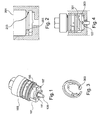
- Fig. 1 shows a coating agent device, which may be a valve and is provided for influencing an output of a coating agent.
- the coating agent device comprises a plug-in mounting base 101 for plug-in mounting of the coating agent device.
- the plug-in mounting base 101 is connected, for example, to a housing 103 of the coating agent device.
- the plug-in mounting base is provided with a helical groove 105, which has an optional fixing groove 107 for receiving a fixing lug.
- the coating means device further comprises on the output side a valve needle 109, which is at least partially surrounded by the plug-in mounting base 101, wherein an end face of the mounting base 101 may be provided with a groove 111 for a sealing ring.
- Fig. 2 shows a housing of a corresponding coating agent device, which comprises a receiving socket 201 for receiving the plug-in mounting base 101 of the coating device Fig. 1 is provided.
- a groove 203 is formed, which may have a spring ring 205.
- the spring ring 205 is for receiving the in Fig. 1 provided Wendelnut 105 is provided.
- Fig. 3 shows a spring ring, which is an elastic element and, for example, at least partially bent in a circle and the spring ring 205 may correspond.
- the spring ring comprises on its inside at least one or two missing fixing lugs 301, which in the fixing groove 107 from Fig. 1 engage, and a rotation with a mounting or retaining pin 303th
- Fig. 4 is a compound of the coating agent device Fig. 1 with the coating device Fig. 2 shown. As in Fig. 4 shown, the resilient fixing lugs 301 of the spring ring 205 engage in the fixing grooves 107.
- the illustrated coating means device may have one or two helical grooves 107.
- the spring ring 205 with the retaining pin 303 and the integrated fixing lugs 301 is in the groove 203 in the receiving socket Fig. 2 used, wherein the retaining pin 303 engage during installation in the helical groove.
- the plug-in mounting base 101 is inserted into the socket 201 and rotated by, for example, 65 ° for rotation. To remove the coating agent device, this is turned back and pulled out. This makes it possible to use direct fasteners.
- large bearing surfaces between the spring ring 205 and the housing can be realized.
- the spring ring 205 can also be easily replaced.
- Fig. 5 shows a coating agent device, for example a coating agent valve, with a housing 501 and a plug-in mounting base 503.
- a coating agent device for example a coating agent valve
- the plug-in mounting base 503, for example in a valve base two retaining pins 505 and 507 are embedded transversely in a cross-sectional plane of the mounting base.
- the retaining pins 505 and 507 have outwardly guided ends 509 through which retaining elements are formed.
- the coating agent device further comprises a valve needle 511, which is arranged on the output side. On the input side, a control input 513 is provided for controlling the valve needle 511 with, for example, compressed air.
- Fig. 6 shows a housing of a coating agent device, such as an air atomizer or a color duplexer, with a receiving socket 601 for receiving the plug-in mounting base 503 from Fig. 5 ,
- the receiving socket 601 comprises axial recesses 603, in which the holding elements 509 can be guided. Furthermore, an example circumferential recess 605 is provided to prevent rotation.
- Fig. 7 shows the coating agent device Fig. 5 in the installed state.
- Figures 8A and 8B show a plan view of the receiving socket 601 with the axial recesses 603, which may be formed for example by axial grooves.
- the receiving socket further comprises a spring ring 801 with angled arms, which are provided with Garwülsten 803 arranged.
- the retaining beads 803 engage in the axial recess 603 to prevent rotation, as shown in FIG Fig. 8B is shown.
- the mounting base 503 is inserted into the receiving socket 601 and rotated, for example, by 90 ° until the anti-rotation locks into place. This rotates automatically when turning back the coating agent device, so that the coating agent device can be pulled out again after a 90 ° rotation.
- Another advantage is the possibility of optical control of the valve position by the engagement of the rotation.
- Fig. 9 shows a coating agent device with a housing 901 and a plug-in mounting base 903, in which in different cross-sectional planes two retaining pins 905 and 907, which, for example, designed as standard pins are, are arranged.
- the coating agent device further comprises a valve needle 909 on the output side.
- the retaining pins 905 and 907 have end portions, which are guided as holding elements to the outside.
- Fig. 10 shows a housing of a coating device with a receiving socket 1001, in which four axial recesses 1003, for example, axial grooves, are arranged. Further, two circumferential grooves 1005 and 1007 are milled with, for example, a radial stop at an angle of about 270 °.
- Fig. 11 shows the coating agent device Fig. 9 in installed condition.
- the plug-in mounting base 903 is inserted into the socket 1001 and rotated, for example, by 90 ° to the stop, whereby the rotation lock into place.
- the rotation lock snaps back by 90 ° when the coating agent device is rotated back, so that the coating agent device can be pulled out.
- the anti-rotation stop is defined and that an optical control of the valve position can be realized by the engagement of the rotation.
- Fig. 12 shows a coating agent device, such as a coating agent valve with a housing 1201 and a plug-in mounting base 1203, the wall is provided with, for example, three ball studs 1205, which may be standardized, transversely in a cross-sectional plane.
- the ball studs 1205 may be at least partially embedded in the mounting base 1203, so that their protruding Sections holding elements to prevent rotation can form.
- Fig. 13 shows a housing of a coating device with a receiving socket 1301 for receiving the mounting base 1203 from Fig. 1
- the receiving socket 1301 is provided with a plurality of, for example, three, helical grooves 1305, the slope of which may each be 10% and the stroke of 1 mm.
- the helical grooves 1305 are milled, for example.
- the ball studs 205 may also be designed as pins. Furthermore, they can be milled as a pin directly from the valve body.
- the helical grooves 305 have the advantage that they allow a high clamping force in a simple housing contour, which ensures a secure connection.
- Fig. 14 shows the coating agent device Fig. 12 in the installed state.
- its mounting base 1203 is inserted into the receiving socket 1301 and rotated, for example by 60 ° to the stop. The rotation is effected via a tension of a needle seal in frictional engagement. To remove the coating agent device, this is turned back and pulled out.
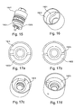
- Fig. 15 shows a coating agent device, such as a valve, with a valve housing 1501 and a plug-in mounting base 1503, which with a journal segment 1505, which can be milled with a clamping slope of 1.5 mm and 20 °, for example, 180 °.
- Fig. 16 shows a housing of a coating device with a receiving socket 1601 for receiving the mounting base 1503 from Fig. 15 ,
- the receiving socket 1601 is provided with a Holding strip 1603 provided, which extends for example by 160 °.
- FIGS. 17A to 17D is the attachment of the in Fig. 15 shown mounting base 1503 shown in the receiving socket 1601.
- Fig. 17A shows the mounting base 1503 in the inserted, but not in the twisted state.
- FIGS. 17B to 17D show the attachment in the non-rotating state.
- Fig. 18 10 shows a coating agent device, for example a valve, with a valve housing 1801 and a plug-in mounting socket 1803 which partially comprises a thread 1804 having axially flattened sections 1805.
- the flattened portions 1805 may be symmetrical cuts, whereby the mounting base according to the "key-hole" principle can be inserted into a receiving socket and twisted in this to prevent rotation.
- the mounting base 1803 is further provided with an optional positioning pin 1806 for positioning its insertion into a receiving socket.
- Fig. 19 shows a housing of a coating device with a receiving socket 1901 for receiving the mounting base 1803.
- the receiving socket 1901 is for example made elongated and includes lateral thread segments 1903 for receiving the threaded portions of the mounting base.
- the receiving socket is also optionally provided with a leakage hole 1905.
- receiving socket 1901 has symmetrically arranged threaded recesses for receiving the thread 1804. However, these can also be arranged asymmetrically.
- Figures 19A, 19B and 19C show an anti-rotation of the mounting base 1803 in the receiving socket 1901.
- Figs. 19B and 19C show the non-rotating condition.
- the thread 1804 of the mounting base may be a M14x1.5 thread, which is milled on two sides, for example, symmetrically or asymmetrically.
- the receiving socket 1901 is recessed on two sides.
- the radial pin 1806 can serve, for example, for unambiguous positioning, wherein a sealing ring can be provided in the end face of a groove 1807 for sealing the leakage.
- the mounting base 1803 is inserted into the receiving socket and, for example, rotated by about 90 ° to 110 °. The rotation is realized via a frictional tension of a needle seal. To remove the coating agent device, this is turned back and pulled out.
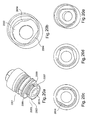
- Fig. 20A 10 shows a coating agent device, for example a valve, with a housing 2001 and a pluggable mounting base 2003, which has asymmetrically arranged and axially expanding threaded sections 2005, which are spaced apart by asymmetrical, axial cutouts 2007.
- the mounting base 2003 further includes a leakage hole 2009 and a groove 2011 for a sealing ring.
- a valve needle which may be arranged in a cylinder of the mounting base 2103.
- Fig. 20B shows a contour of a housing of a corresponding coating device, such as a nebulizer or a color changer, with an asymmetrically shaped receiving socket 2002, which has asymmetrically arranged thread segments 2004.
- a corresponding coating device such as a nebulizer or a color changer
- the coating agent device is off Fig. 20A shown in the installed state. It shows the Fig. 20C an inserted state, wherein the FIGS. 20D to 20E clarify the rotation.
- the thread 2005 may for example be milled off asymmetrically on two sides by 30 °, whereby, corresponding to this, the same thread can be introduced into the receiving bushing 2002 and then cut out on two sides.
- the unique positioning of the mounting base 2003 in the receiving socket 2002 can be realized via the asymmetric surfaces according to the "key-hole" principle.
- the rotation is realized via a frictional tension of a needle seal. To install the coating agent device, for example, this is rotated by about 75 ° and thereby secured against rotation. To remove the coating agent device, this is turned back and pulled out. It is advantageous, in particular, that the positioning can be visually made visible via a wedge shape and that no positioning pin is necessary.
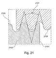
- Fig. 21 shows a section of a mounting base 2101 of a coating agent device 2103.
- the mounting base 2101 is provided with a special thread 2105, the slope can be 1.5 to 3.
- a helix angle of the thread is as in Fig. 21 represented, for example, 30 °.
- a section of a receiving socket 2107 which forms a valve housing, shown.
- the receiving socket comprises a wall which is provided with a corresponding thread 2109.
- a helix angle of the thread 2105, 2109 may be 30 °, for example.
- the threads and / or the thread flanks are rounded, whereby an increased high voltage resistance is achieved.
- the threads 2105, 2109 may further have a diameter of, for example, 10, 11, 12 or 14 mm.
- the threads 2105 and 2109 can also be, for example, special threads, for example the M11x3 thread with rounded thread root and rounded thread crests.
- coating agent devices shown can, for example, self-locking and / or rotationally secured against rotation via a positive connection or via a frictional connection. Furthermore, the features of the above coating agent devices can be combined individually or in groups, whereby further advantageous embodiments can be realized.
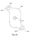
- Fig. 22 shows a coating agent device, for example a coating agent valve, with a drive interface 2201, one of these downstream housing 2203 and a valve needle 2205.
- the drive interface 2201 has a substantially oval cross section, wherein outwardly curved connecting portions 2207, each with a bore 2209 for receiving Screws are provided are provided.
- the drive interface 2201 further comprises a control input 2211, via which compressed air for driving the valve needle 2205 of the coating agent device can be fed.
- Fig. 23 shows a plan view of the drive interface 2201.
- Fig. 24 shows a cross section of the housing 2203 of the coating agent device Fig. 22 , The cross section is substantially oval and takes on the shape of the cross section of the drive interface 2201.
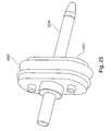
- Fig. 25 shows the valve needle 2205 Fig. 22 which is arranged in the housing 2203.
- the valve needle 2205 is arranged in a piston element 2501, which is acted upon by compressed air, whereby the valve needle 2205 can be driven.
- the piston member 2501 includes laterally a circumferential seal 2503, the cross section of which, like the cross section of the piston member 2501 is oval and the shape of the cross section of the housing 2203 receives.
- the valve needle 2205 is disposed together with the piston member in a cylinder of the housing 2203.
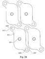
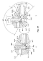
- Fig. 26 shows a plan view of an arrangement of a plurality of coating agent devices, as shown in FIG Fig. 22 are shown.
- the elongated design of the valve interface 2201 allows for such as shown in FIG Fig. 26 indicated, at least partially form-fitting, a tight arrangement of the coating agent devices side by side. This increases the packing density of the coating agent devices in a coating device of the aforementioned type.
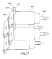
- Fig. 27 shows a side plan view of the in Fig. 26 illustrated arrangement of the coating agent elements Fig. 22 , As in Fig. 27 As shown, the coating means devices, which may for example be valves, can advantageously be arranged close to each other due to the oblong shape of the cross sections of the drive interface 2201 and the housing 2203.
- valve drive Due to the oval design of the valve drive, it can have a compact design, wherein a number of the valves which can be arranged next to one another and can open on a channel can be increased. In addition, is opposite one round piston expected by the use of the oval piston or piston portion increased switching force.
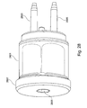
- Fig. 28 10 shows a coating agent device, such as a coating agent valve, having a housing 2801 and a plurality of valve pins 2803 and 2805.
- the coating agent device includes a drive interface 2807, which may include one or more control inputs 2809 for driving the valve needles 2803. These are preferably designed parallel to the outside and operated separately from each other, so that the valve needle 2803 can be used for short flushing with air and the valve needle 2805 for short flushing with a solvent.
- the valve needle 2803 for dispensing the coating agent and the valve needle 2805 for returning it may be provided.
- the drive interface 2807 may be, for example, as in FIG Fig. 26 be shown oval or circular or square executed.
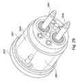
- Fig. 29 shows a front view of the coating agent device Fig. 28 , As in Fig. 29 shown, each valve needle 2803, 2805 is guided in a respective needle respectively associated cylinder or channel 2901 or 2903.
- Fig. 30 shows the coating agent device Fig. 28 , which is connected to a coating device 3001, for example an atomizer or a color changer.
- the coating device 3001 comprises two valve seats 3003 and 3005, which are respectively provided for the respective valve needle 2803 or 2805.
- Each needle 2803 or 2805 is movable in an associated cylinder or channel 3007 or 3009, wherein auxiliary channels 3011 and 3013 are provided perpendicular thereto.
- the auxiliary channels 3011 and 3013 for example, for flushing the valve needles 2803 or 2805 or be provided for returning the respective coating agent.
- the coating agents are guided over the channels 3007 and 3009, enveloping the respective needle 2803 or 2805.
- Such double valves can be realized, for example, as function valves, color changers or atomizers in all possible combination variants with, for example, needles of different lengths, as a single valve block with two functions or as a multiple valve block with multiple functions.
- Such valves can be arranged on one side or opposite or in a circle, wherein the control can be realized directly via a hose connection or indirectly via a supply bore.
- the valves can also be strung together in analogy to pneumatic valves.
- the housing 2801 and the drive interface 2807 may be circular or oval.
- the valve needles 2805 and 2803 may be provided with oval piston members 2501 each sealed with seals 2503.
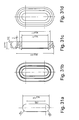
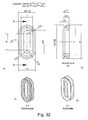
- FIGS. 31A to 31D show views of an oval piston element of the aforementioned type.
- FIGS. 32A to 32C show views of oval seals, which can cooperate for example with the oval piston element.
- Fig. 33 shows a valve needle with a valve needle head 3301 and a valve needle shaft 3303, which may be made of plastic.
- the valve needle shaft 3303 is sheathed with a sleeve 3305 made of a composite material or a ceramic material may be formed, so that the sleeve 3305 is more resistant to abrasion than the valve needle shaft 3303.
- the sleeve 3305 may further be formed of metal or DLC (diamond-like carbon).
- An end of the valve needle facing away from the valve needle head 3301 can, for example, be flattened several times and have, for example, a flushing section 3307, a sealing section 3309 and a guide section 3311.
- the purge section 3307 serves to improve a purge of the valve needle, such as a short purge of the same.
- the flushing section 3307 tapers, for example, at a helix angle of 10 ° or, with respect to a longitudinal axis of the valve needle, at an angle of 5 °.
- Downstream of the flushing section 3307 immediately downstream is a sealing section 3309, which cooperates with a valve seat during operation of the valve needle and ensures sealing.
- the sealing portion tapers, for example, at a helix angle of 30% or, with respect to the longitudinal axis of the valve needle, at an angle of 15%. Downstream of the sealing section 3309, downstream of the guide section 3311, which serves to insert the valve needle tip into the valve seat.
- the guide portion 3311 is preferably made shorter than the other two portions 3307 and 3309 and tapers at a helix angle of 120 ° or, with respect to the aforementioned longitudinal axis, at an angle of 60 °. Both the sleeve 3305 and the sections 3307 to 3311 are each optional.
- Fig. 34A shows a first valve needle 3401 of a coating agent device, which is arranged in a cylinder or channel 3403 of a coating device.
- the cylinder 3403 includes a valve seat 3405 which seals by means of a sealing portion 3407 of the valve needle 3401 is.
- the sealing portion 3407 corresponds to, for example, the sealing portion 3307.
- the valve needle 3401 further includes a guide portion 3409, which may correspond to the guide portion 3311, and a purge portion 3411, which may correspond to the purge portion 3307.
- a flushing gap is increased.
- the coating agent device may further include a second needle 3413 disposed perpendicular to the valve needle 3401 in a channel 3415.
- the second valve needle may also have a flushing portion 3417, a sealing portion 3419 and a guide portion 3421, wherein the portions 3417, 3419 and 3421 may have the features of the portions 3307, 3309 and 3311.
- the second valve needle 3413 can be actuated, for example, to rinse the first valve needle 3401.
- the coating agent device comprises an auxiliary channel 3423, which opens into the coating agent channel 3403.
- Fig. 34B illustrates the helix angle of the guide portion 3409, the sealing portion 3407 and the flushing portion 3411 of the first valve needle 3401 in the displaced state from the valve seat.
- the valve seat comprises a sealing portion 3425 corresponding to the sealing portion 3407.
- valve seat may for example have a sealing portion 3427, which is bevelled, for example, at a helix angle of 90 °.
- This valve seat may further include another tapered portion 3429 which tapers and is provided at an angle of, for example, 90 °, to increase a clearance between the valve seat and the purge portion 3417 of the second valve needle 3413.
- Fig. 35 shows a multi-tapered coating agent valve 3501, which is in a closed state in a valve seat 3503 of a coating agent device 3505, such as a nebulizer or a color changer sitting.
- the valve needle 3501 includes a guide portion 3507, a seal portion 3509, and a purge portion 3511 having the features of FIGS Fig. 33 may have shown sections.
- a seal portion 3509 sealingly cooperates with the valve seat 3503, and both the guide portion 3507 and the flushing portion 3511 are not in contact therewith.
- the valve needle 3501 is disposed in a cylinder 3513, and by providing the slanted rinsing portion 3511, a larger clearance for rinsing the needle 3501 is provided.
- the coating agent device 3505 may have an auxiliary channel 3515.
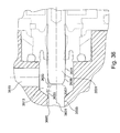
- Fig. 36 shows the valve needle Fig. 35 in the open state.
- the sealing portion 3509 may taper with respect to the longitudinal axis 3601 at a sealing angle 3603, which may be 15 °, for example.
- the valve seat 3503 comprises a sealing portion 3605, which also tapers under the same sealing angle 3603.
- Fig. 37 shows a valve needle tip with a guide portion 3701, a sealing portion 3703 and a flushing portion 3705.
- the guide portion 3701 tapers with respect to a longitudinal axis 3707 by a guide angle 3709, which may be 60 °.
- the sealing portion 3703 tapers with respect to the longitudinal axis 3707 by a sealing angle 3711, which may be 15 °.
- the flushing portion 3705 tapers with respect to the longitudinal axis 3707 by a rinsing angle 3713, which may be 5 °
- the valve needle tip may for example be formed of plastic and with a hard valve seat, which is formed, for example, made of stainless steel, cooperate.
- the seal in the valve seat can be accomplished, for example, without grinding, with a process-technically secure seal can be realized in particular in a needle seat in a transition between a soft material and a hard material.
- the joining surface is substantially increased according to the invention, whereby a risk of breakage can be reduced.
- a wear-resistant surface of the valve needle can be realized in the area of the sealing of the needle to the valve drive.
- valve seat in the housing of the corresponding coating agent device in contrast to the threefold angled tip of the valve needle, is designed, for example, over two angle stages.
- the sealing areas in this case preferably have the same angles on both sides.
- the coating agent devices described above can be valves which can be used as needle valves and / or seat valves, as function valves, color changer valves, atomizer valves or main needle valves in painting technology.
- the coating devices can be any of those used in painting, such as atomizers or color changers, which can interact with such coating agent devices.
Landscapes
- Engineering & Computer Science (AREA)
- General Engineering & Computer Science (AREA)
- Mechanical Engineering (AREA)
- Nozzles (AREA)
- Spray Control Apparatus (AREA)
- Coating Apparatus (AREA)
- Valve Housings (AREA)
- Electrostatic Spraying Apparatus (AREA)
- Lift Valve (AREA)
- Details Of Valves (AREA)
- Prostheses (AREA)
- Road Signs Or Road Markings (AREA)
Abstract
Die Erfindung betrifft eine Beschichtungsmittelvorrichtung, insbesondere ein Beschichtungsmittelventil, zur Beeinflussung einer Ausgabe eines Beschichtungsmittels, gekennzeichnet durch einen steckbaren Befestigungssockel (101) zur steckbaren Halterung der Beschichtungsmittelvorrichtung.The invention relates to a coating agent device, in particular a coating agent valve, for influencing an output of a coating agent, characterized by a plug-in mounting base (101) for plug-in mounting of the coating agent device.
Description
Die vorliegende Erfindung betrifft das Gebiet der Beschichtung von Werkstücken, insbesondere von Karosseriebauteilen.The present invention relates to the field of coating workpieces, in particular body components.
Zur Beschichtung von Werkstücken werden üblicherweise Beschichtungsvorrichtungen, beispielsweise elektrostatische Rotationszerstäuber oder Farbwechsler, eingesetzt, welchen das zu applizierende Beschichtungsmittel beispielsweise mittels eines Ventils, beispielsweise eines Beschichtungsmittelventils, zugeführt wird.Coating devices, for example electrostatic rotary atomizers or color changers, are usually used for coating workpieces, to which the coating agent to be applied is supplied, for example, by means of a valve, for example a coating agent valve.
Die Ventile in der Lackiertechnik sind üblicherweise mit einem runden Pneumatikkolben aufgebaut, wobei der pneumatische Antrieb des Ventils über einen Steuerluftraum, über eine Kolbendichtung und über eine Feder erfolgen kann, welche sich in einem runden Gehäuse befinden. In dem runden Gehäuse ist üblicherweise ein Zylinder ausgebildet, in welchem eine bewegbare Ventilnadel angeordnet ist. Im Betrieb werden die Ventilnadeln daher dem jeweils applizierten Beschichtungsmittel ausgesetzt und müssen, beispielsweise durch Kurzspülen mit Luft, gereinigt werden. Aufgrund der Anordnung der Ventilnadeln in Beschichtungsmittelzylindern ist eine derartige Reinigung jedoch konstruktionsbedingt schwierig. Die Beschichtungsmittelventile werden zudem ausgabeseitig in die Beschichtungsmittelvorrichtungen eingeschraubt, sodass sie zwecks Reinigung oder Wartung nur mit einem erhöhten Aufwand abgeschraubt werden müssen. Derartige Gewindeverbindungen lassen ferner auch keine dichtere Anordnung der Beschichtungsmittelventile in einer Beschichtungsmittelvorrichtung zu, was die Systemeffizienz reduziert. Die bekannten Beschichtungssysteme mit derartigen Beschichtungsmittelventilen und Beschichtungsmittelvorrichtungen sind daher wartungsintensiv und nicht effizient.The valves in the painting technique are usually constructed with a round pneumatic piston, wherein the pneumatic drive of the valve can take place via a control air space, a piston seal and a spring, which are located in a round housing. In the round housing, a cylinder is usually formed, in which a movable valve needle is arranged. During operation, the valve needles are therefore exposed to the particular coating agent applied and must be cleaned, for example by brief rinsing with air. However, due to the arrangement of the valve needles in coating medium cylinders, such cleaning is difficult by design. The coating agent valves are also the output side screwed into the coating agent devices, so they need to be unscrewed for cleaning or maintenance only with increased effort. Furthermore, such threaded connections also do not allow a denser arrangement of the coating agent valves in a coating agent device too, which reduces system efficiency. The known coating systems with such coating agent valves and coating agent devices are therefore maintenance-intensive and not efficient.
Bekannte Ventile sind ferner aus einem bzw. aus zwei Werkstoffen, üblicherweise Edelstahl und Kunststoff, aufgebaut. Die Verbindung dieser Werkstoffpaarungen erfolgt üblicherweise über Verschraubungen, Verklebungen, Anspritzungen quer zur Symmetrieachse der Ventilnadel. Im Betrieb sorgen diese Werkstoffpaarungen für Abreibungen, welche eine erhöhte Wartungsfrequenz nach sich ziehen.Known valves are also constructed of one or two materials, usually stainless steel and plastic. The connection of these material combinations usually takes place via screw connections, gluing, sprues transversely to the axis of symmetry of the valve needle. In operation, these material combinations provide for abrasions, which entail an increased maintenance frequency.
Ferner ist zum Stand der Technik hinzuweisen auf
Es ist die Aufgabe der Erfindung, ein effizienteres sowie wartungs- und reinigungsfreundlicheres Beschichtungssystemkonzept zu schaffen. Diese Aufgabe wird durch die Merkmale der unabhängigen Ansprüche gelöst. Vorteilhafte Weiterbildungen der Erfindung sind Gegenstand der abhängigen Ansprüche.It is the object of the invention to provide a more efficient and maintenance-friendly and cleaning-friendly coating system concept. This object is solved by the features of the independent claims. Advantageous developments of the invention are the subject of the dependent claims.
Die Erfindung basiert auf der Erkenntnis, dass ein effizienteres Beschichtungssystemkonzept dadurch realisiert werden kann, dass zur Kopplung von Beschichtungsmittelvorrichtungen, beispielsweise Beschichtungsmittelventilen, mit Beschichtungsvorrichtungen wie beispielsweise Zerstäubern oder Farbwechslern Steckverbindungen eingesetzt werden können, welche auch verdrehgesichert sein können. So kann beispielsweise ein Beschichtungsmittelventil effizient mit einem Farbwechsler beispielsweise mittels einer Bajonett-Verbindung verbunden werden und kann daher schnell und einfach ausgetauscht werden.The invention is based on the finding that a more efficient coating system concept can be realized in that plug-in connections can be used for coupling coating agent devices, for example coating agent valves, with coating devices, such as atomizers or color changers, which can also be rotationally secured. Thus, for example, a coating agent valve can be efficiently connected to a color changer, for example by means of a bayonet connection and can therefore be replaced quickly and easily.
Die Erfindung basiert auf der weiteren Erkenntnis, dass ein reinigungsfreundlicheres Beschichtungssystemkonzept durch eine geeignete geometrische Ausgestaltung der Ventilnadel eines Beschichtungsmittelventils realisiert werden kann. Hierzu können insbesondere die Enden der Ventilnadeln mit einem zusätzlichen, sich unter einem bestimmten Winkel verjüngenden Abschnitt versehen werden, durch welchen der die Ventilnadel umgebende Raum in einem Zylinder vergrößert wird.The invention is based on the further realization that a cleaning-friendly coating system concept can be realized by a suitable geometric design of the valve needle of a coating agent valve. For this purpose, in particular, the ends of the valve needles can be provided with an additional, tapered at a certain angle portion through which the space surrounding the valve needle in a cylinder is increased.
Die Erfindung basiert auf der weiteren Erkenntnis, dass ein wartungsfreundlicheres Beschichtungssystemkonzept durch eine abriebresistentere Ausführung einer Ventilnadel eines Beschichtungsmittelventils realisiert werden kann. Hierzu kann der üblicherweise eingesetzte Kunststoffschaft der Ventilnadel zusätzlich mit einer abriebfesteren Hülse ummantelt werden, wodurch der schädliche Abrieb minimiert und die Lebensdauer der Ventilnadel erhöht werden.The invention is based on the further realization that a more maintenance-friendly coating system concept can be realized by a wear-resistant design of a valve needle of a coating agent valve. For this purpose, the usually used plastic shaft of the valve needle can be additionally sheathed with a more abrasion-resistant sleeve, whereby the harmful abrasion minimized and the life of the valve needle can be increased.
Die Erfindung basiert auf der weiteren Erkenntnis, dass eine Packungsdichte der Beschichtungsmittelvorrichtungen wie beispielsweise Beschichtungsventile in einer Beschichtungsvorrichtung der vorgenannten Art dadurch erhöht werden kann, dass eine rückseitige Antriebsschnittstelle sowie ein Gehäuse eines Beschichtungsmittelventils nicht kreisrund, sondern beispielsweise länglich ausgeführt sind, und beispielsweise formschlüssige geometrische Formen aufweisen, so dass mehrere Beschichtungsmittelvorrichtungen näher aneinander, beispielsweise formschlüssig in einer Beschichtungsmittelvorrichtung wie beispielsweise einem Farbwechsler, angeordnet werden können.The invention is based on the further realization that a packing density of the coating agent devices such as coating valves in a coating device of the aforementioned type can be increased by a rear drive interface and a housing of a coating agent valve are not circular, but elongated, for example, and form-fitting geometric shapes have, so that a plurality of coating means devices closer together, for example, can be arranged in a form-fitting manner in a coating agent device such as a color changer.
Gemäß einem Aspekt betrifft die Erfindung eine Beschichtungsmittelvorrichtung, beispielsweise ein Beschichtungsmittelventil, zur Beeinflussung einer Ausgabe eines Beschichtungsmittels, beispielsweise eines Automobillacks. Die Beschichtungsmittelvorrichtung umfasst bevorzugt einen steckbaren Befestigungssockel zur Halterung derselben in beispielsweise einer Beschichtungsvorrichtung wie beispielsweise einem Zerstäuber oder einem Farbwechsler. Die Beschichtungsmittelvorrichtung wird somit durch eine Steckverbindung gehaltert, so dass sie schnell ausgetauscht werden kann.According to one aspect, the invention relates to a coating agent device, for example a coating agent valve, for influencing an output of a coating agent, for example, an automotive paint job. The coating agent device preferably comprises a plug-in mounting base for holding the same in, for example, a coating device such as, for example, an atomizer or a color changer. The coating agent device is thus supported by a plug connection so that it can be exchanged quickly.
Im Folgenden werden beispielsweise Beschichtungsmittelventile beispielhaft beschrieben. Die nachstehenden Ausführungen gelten jedoch sinngemäß für beliebige Ventile, welche zur Beschichtung von Werkstücken eingesetzt werden können.For example, coating agent valves will be described below by way of example. However, the following statements apply mutatis mutandis to any valves that can be used for coating workpieces.
Gemäß einer Ausführungsform umfasst die Beschichtungsmittelvorrichtung eine bewegbare Ausgabeeinrichtung, beispielsweise eine Ventilnadel, zur steuerbaren Ausgabe des Beschichtungsmittels. Der steckbare Befestigungssockel kann die bewegbare Ausgabeeinrichtung und/oder einen Beschichtungsmittelzylinder ausgabeseitig zumindest teilweise umfassen oder umgeben.According to one embodiment, the coating agent device comprises a movable dispensing device, for example a valve needle, for the controllable dispensing of the coating agent. The pluggable mounting base may at least partially surround or surround the movable output device and / or a coating agent cylinder on the output side.
Gemäß einer Ausführungsform umfasst die Beschichtungsmittelvorrichtung einen Ausgang zur Ausgabe des Beschichtungsmittels, wobei der steckbare Befestigungssockel vorgesehen sein kann, den Ausgang der Beschichtungsmittelvorrichtung mit einer Beschichtungsvorrichtung, beispielsweise mit einem Zerstäuber oder einem Farbwechsler, zu koppeln. Somit wird eine einfache und wartungsfreundliche, ausgabeseitige Verbindung der Beschichtungsmittelvorrichtung mit der Beschichtungsvorrichtung ermöglicht.According to one embodiment, the coating agent device comprises an outlet for dispensing the coating agent, wherein the pluggable mounting base may be provided to couple the outlet of the coating agent device with a coating device, for example with a sprayer or a color changer. Thus, a simple and easy to maintain, output side connection of the coating agent device is made possible with the coating device.
Gemäß einer Ausführungsform kann der steckbare Befestigungssockel beispielsweise mittels einer Rast- oder einer Schnappanordnung einrastbar oder einschnappbar sein, wodurch der Sitz des Befestigungssockels gesichert werden kann.According to one embodiment, the plug-in mounting base, for example by means of a latching or a snap-on arrangement can be latched or snapped, whereby the seat of the mounting base can be secured.
Gemäß einer Ausführungsform ist der steckbare Befestigungssockel verdrehsicherbar. Die Verdrehsicherung kann beispielsweise nach dem Einstecken des steckbaren Befestigungssockels in beispielsweise eine Aufnahmebuchse einer Beschichtungsvorrichtung durchgeführt werden.According to one embodiment, the plug-in mounting base is against rotation. The rotation can be performed, for example, after inserting the plug-in mounting base in, for example, a receiving socket of a coating device.
Gemäß einer Ausführungsform umfasst der steckbare Befestigungssockel eine Bajonett-Verbindung, beispielsweise eine symmetrische oder eine unsymmetrische oder eine mit einem Bajonettgewinde, das seitlich in axialer Richtung zumindest teilweise abgeflacht sein kann, versehene Bajonett-Verbindung. Dadurch kann eine rasche und sichere Verdrehsicherung realisiert werden.According to one embodiment, the plug-in mounting base comprises a bayonet connection, for example, a bayonet connection, which is symmetrical or asymmetrical or has a bayonet thread which can be at least partially flattened laterally in the axial direction. As a result, a rapid and secure rotation can be realized.
Gemäß einer Ausführungsform ist zur Verdrehsicherung des steckbaren Befestigungssockels zumindest ein Halteelement vorgesehen, das sich von einer Wandung des steckbaren Befestigungssockels nach außen erstreckt. Zur Verdrehsicherung kann in der Wandung auch zumindest eine Ausnehmung gebildet sein, welche zur Aufnahme eines Halteelementes vorgesehen sein kann. Dadurch kann eine sichere Einrastung einer Bajonett-Verbindung sichergestellt werden.According to one embodiment, at least one holding element is provided for preventing rotation of the plug-in mounting base, which extends from a wall of the plug-in mounting base to the outside. To prevent rotation, at least one recess may be formed in the wall, which may be provided for receiving a holding element. As a result, a secure engagement of a bayonet connection can be ensured.
Gemäß einer Ausführungsform ist in dem steckbaren Befestigungssockel ein Haltestift eingebettet, dessen nach außen geführtes Ende ein Halteelement bildet. Darüber hinaus können beide Enden des Haltestiftes parallel nach außen geführt werden und so gegenüberliegende Halteelemente bilden. Ferner können in dem steckbaren Befestigungssockel mehrere Haltestifte in beispielsweise derselben Querschnittsebene oder in unterschiedlichen Querschnittsebenen eingebettet sein, wobei jeweils zumindest ein Ende des jeweiligen Haltestiftes nach außen geführt ist und ein Halteelement bildet. Dadurch kann insbesondere bei einer verdrehgesicherten Verbindung ein Verdrehsicherungsanschlag realisiert werden.According to one embodiment, a retaining pin is embedded in the plug-in mounting base, the outwardly guided end of which forms a holding element. In addition, both ends of the retaining pin can be guided parallel to the outside and thus form opposite holding elements. Furthermore, a plurality of retaining pins may be embedded in, for example, the same cross-sectional plane or in different cross-sectional planes in the plug-in mounting base, wherein in each case at least one end of the respective retaining pin is guided to the outside and forms a retaining element. This can In particular, in a non-rotating connection a Verdrehsicherungsanschlag be realized.
Gemäß einer Ausführungsform kann das Halteelement ein Kugelbolzen sein. Ferner kann eine Wandung des steckbaren Befestigungssockels mit einer Mehrzahl von Kugelbolzen versehen sein, welche in derselben Querschnittsebene der Wandung oder in unterschiedlichen Querschnittsebenen der Wandung angeordnet sind und jeweils ein Halteelement bilden, wodurch ein Drehwinkel der Verdrehsicherungsverbindung beschränkt werden kann.According to one embodiment, the retaining element may be a ball stud. Further, a wall of the plug-in mounting base may be provided with a plurality of ball pins, which are arranged in the same cross-sectional plane of the wall or in different cross-sectional planes of the wall and each form a holding element, whereby a rotation angle of the anti-rotation connection can be limited.
Gemäß einer Ausführungsform ist eine Wandung des steckbaren Befestigungssockels zur Verdrehsicherung mit einer zumindest teilweise umlaufenden Ringnut oder Halteleiste versehen. Dadurch kann eine reibschlüssige Verdrehsicherung einfach realisiert werden.According to one embodiment, a wall of the pluggable mounting base for preventing rotation is provided with an at least partially encircling annular groove or retaining strip. Thereby, a frictional rotation can be easily realized.
Gemäß einer Ausführungsform umfasst eine Wandung des steckbaren Befestigungssockels zur Verdrehsicherung ein Gewinde, das beispielsweise seitlich axial abgeflacht werden kann, wodurch der steckbare Befestigungssockel nach dem "Schlüssel-Loch"-Prinzip einsteckbar und verdrehsicherbar ist. Die Wandung des steckbaren Befestigungssockels kann hierzu sich in axialer Richtung des steckbaren Befestigungssockels erstreckende gewindefreie oder mit gegenüber anderen Wandungsabschnitten der Wandung mit flacheren Gewindegängen oder Gewindeflanken versehene Wandungsabschnitte aufweisen, welche rotationssymmetrisch oder rotationsunsymmetrisch angeordnet sind. Dadurch kann eine einfache und sichere Verdrehsicherung des steckbaren Befestigungssockels realisiert werden.According to one embodiment, a wall of the plug-in mounting base for preventing rotation comprises a thread which can be axially flattened, for example laterally, whereby the plug-in mounting base according to the "key-hole" principle can be inserted and against rotation. For this purpose, the wall of the pluggable fastening base can have thread-free or, with respect to other wall sections of the wall, flattened thread sections or thread flanks extending in the axial direction of the pluggable fastening base, which are arranged rotationally symmetrically or rotationally asymmetrically. As a result, a simple and secure rotation of the plug-in mounting base can be realized.
Gemäß einem weiteren Aspekt betrifft die Erfindung eine Beschichtungsmittelvorrichtung zur Beeinflussung einer Ausgabe eines Beschichtungsmittels. Die Beschichtungsmittelvorrichtung umfasst einen Befestigungssockel zur Halterung der Beschichtungsmittelvorrichtung in beispielsweise einer Beschichtungsvorrichtung wie beispielsweise einem Zerstäuber oder einem Farbwechsler. Bevorzugt ist die Wandung des Befestigungssockels mit einem Gewinde versehen, dessen Steigung in einem Steigungsbereich zwischen 1,5 und 3 liegt. Dadurch wird eine schnell lösbare und somit wartungsfreundliche Befestigung der Beschichtungsmittelvorrichtung erzielt. Die Beschichtungsmittelvorrichtung kann gemäß einer Ausführungsform die Merkmale der vorstehend und/oder nachfolgend genannten Beschichtungsmittelvorrichtungen aufweisen.According to a further aspect, the invention relates to a coating agent device for influencing an output a coating agent. The coating agent device comprises a mounting base for holding the coating agent device in, for example, a coating device such as, for example, an atomizer or a color changer. Preferably, the wall of the mounting base is provided with a thread whose pitch is in a pitch range between 1.5 and 3. As a result, a fast detachable and thus maintenance-friendly attachment of the coating agent device is achieved. The coating agent device according to one embodiment can have the features of the coating agent devices mentioned above and / or below.
Gemäß einer Ausführungsform umfasst das Gewinde abgerundete Gewindeflanken und/oder abgerundete Gewindegänge, welche unter einem Rundungsschrägungswinkel von beispielsweise 28°, 29°, 30°, 31° oder 32° abgerundet sein können. Dadurch wird ein schneller Gewindeeingriff ermöglicht.According to one embodiment, the thread comprises rounded thread flanks and / or rounded threads, which may be rounded off at a rounding bevel angle of for example 28 °, 29 °, 30 °, 31 ° or 32 °. This allows a quick thread engagement.
Gemäß einer Ausführungsform ist das Gewinde umlaufend und stetig ausgeführt. Die Wandung kann jedoch sich axial erstreckende gewindefreie Abschnitte aufweisen, wodurch auch eine steckbare Verbindung realisiert werden kann. In diesem Fall dient das Gewinde zur raschen Verdrehsicherung.According to one embodiment, the thread is circumferential and continuous. However, the wall can have axially extending thread-free sections, whereby a pluggable connection can be realized. In this case, the thread serves for rapid rotation.
Gemäß einer Ausführungsform umfasst die Beschichtungsmittelvorrichtung einen Ausgang zur Ausgabe des Beschichtungsmittels, wobei der Befestigungssockel vorgesehen ist, den Ausgang mit einer Beschichtungsvorrichtung, beispielsweise mit einem Zerstäuber oder einem Farbwechsler zu koppeln. Der Befestigungssockel ist somit ausgangsseitig angeordnet.According to one embodiment, the coating agent device comprises an outlet for dispensing the coating agent, wherein the mounting base is intended to couple the outlet with a coating device, for example with a sprayer or a color changer. The mounting base is thus arranged on the output side.
Gemäß einem weiteren Aspekt betrifft die Erfindung eine Beschichtungsmittelvorrichtung der vorgenannten Art, mit einer Antriebsschnittstelle zum Ankoppeln einer Antriebsvorrichtung, insbesondere eines pneumatischen Ventilantriebs, an die Beschichtungsmittelvorrichtung, welche ein Beschichtungsventil sein kann. Bevorzugt weist die Antriebsschnittstelle einen länglichen Querschnitt auf, wodurch eine Packungsdichte von gleichartigen Beschichtungsmittelvorrichtungen durch eine raumsparende Nebeneinanderanordnung derselben erhöht werden kann.According to a further aspect, the invention relates to a coating agent device of the aforementioned kind, with a Drive interface for coupling a drive device, in particular a pneumatic valve drive, to the coating agent device, which may be a coating valve. Preferably, the drive interface has an elongated cross section, whereby a packing density of similar coating agent devices can be increased by a space-saving juxtaposition thereof.
Gemäß einer Ausführungsform ist der Querschnitt der Antriebsschnittstelle, d.h. der Verbindungsquerschnitt derselben, vollständig oder zumindest abschnittsweise oval und beispielsweise geformt, eine Mehrzahl von gleichartigen Beschichtungsmittelvorrichtungen zumindest teilweise formschlüssig nebeneinander anzuordnen. Hierzu kann die Antriebsschnittstelle beispielsweise formschlüssige Elemente, wie beispielsweise konvexe oder konkave Bereiche, aufweisen, die bei einer Nebeneinanderanordnung von gleichartigen Beschichtungsmittelvorrichtungen ineinander eingeführt werden können, wodurch die Packungsdichte der Beschichtungsmittelvorrichtungen erhöht werden kann.According to one embodiment, the cross-section of the drive interface, i. the connecting cross section thereof, completely or at least partially oval and, for example, shaped to arrange a plurality of similar coating means devices at least partially form-fitting side by side. For this purpose, the drive interface may, for example, form-fitting elements, such as convex or concave areas, which can be introduced into one another in a juxtaposition of similar coating agent devices, whereby the packing density of the coating agent devices can be increased.
Gemäß einer Ausführungsform umfasst die Antriebsschnittstelle zumindest zwei konvexe Befestigungsbereiche, welche diagonal gespiegelt angeordnet sein können, zur mechanischen Halterung der Beschichtungsmittelvorrichtung unter Verwendung von beispielsweise einer Schraubverbindung. Dadurch wird in vorteilhafter Weise eine axiale Sicherung der Beschichtungsmittelvorrichtung, welche beispielsweise steckbar sein kann, realisiert.According to one embodiment, the drive interface comprises at least two convex attachment regions, which may be arranged diagonally mirrored, for mechanical retention of the coating agent device using, for example, a screw connection. As a result, an axial securing of the coating agent device, which may for example be pluggable, is realized in an advantageous manner.
Gemäß einer Ausführungsform umfasst die Antriebsschnittstelle zumindest einen Steuereingang zur Aufnahme eines Antriebssignals der Antriebsvorrichtung, beispielsweise eines Luftdrucksignals, zum Antreiben einer Ventilnadel der Beschichtungsmittelvorrichtung.According to one embodiment, the drive interface comprises at least one control input for receiving a drive signal of the drive device, for example an air pressure signal, for driving a valve needle of the coating agent device.
Gemäß einer Ausführungsform nimmt ein Querschnitt eines der Antriebsschnittstelle nachgeordneten Gehäuses der Beschichtungsmittelvorrichtung zumindest teilweise den Querschnitt der Antriebsschnittstelle auf. Somit entspricht eine Kontur des Gehäuses der Beschichtungsmittelvorrichtung vollständig oder zumindest teilweise einer Kontur der Antriebsschnittstelle, wodurch eine effiziente Anordnung einer Mehrzahl von gleichartigen Beschichtungsmittelvorrichtungen ermöglicht wird.According to one embodiment, a cross-section of a housing downstream of the drive interface of the coating agent device at least partially assumes the cross-section of the drive interface. Thus, a contour of the housing of the coating agent device completely or at least partially corresponds to a contour of the drive interface, whereby an efficient arrangement of a plurality of similar coating agent devices is made possible.
Die Beschichtungsmittelvorrichtung kann ferner die Merkmale der vorstehend und/oder nachfolgend genannten Beschichtungsmittelvorrichtungen aufweisen.The coating agent device can furthermore have the features of the coating agent devices mentioned above and / or below.
Gemäß einem weiteren Aspekt betrifft die Erfindung eine Beschichtungsmittelvorrichtung der vorgenannten Art, welche ein Beschichtungsmittelventil mit einer Mehrzahl von nach außen geführten Ventilnadeln ist oder umfasst. Die Ventilnadeln können beispielsweise unterschiedliche Ventilsitze einer Beschichtungsvorrichtung, mit welcher die Beschichtungsmittelvorrichtung koppelbar ist, abdichten, wodurch eine Beschichtungseffizienz gesteigert werden kann.According to a further aspect, the invention relates to a coating agent device of the aforementioned type, which is or comprises a coating agent valve with a plurality of outwardly guided valve pins. The valve needles can, for example, seal different valve seats of a coating device, with which the coating agent device can be coupled, whereby a coating efficiency can be increased.
Gemäß einer Ausführungsform weisen zumindest zwei Ventilnadeln der Mehrzahl der Ventilnadeln eine unterschiedliche geometrische Form auf, beispielsweise eine unterschiedliche Länge und/oder eine unterschiedliche Dicke, so dass unterschiedliche Ventilnadeln für unterschiedliche Zwecke eingesetzt werden können.According to one embodiment, at least two valve needles of the plurality of valve needles have a different geometric shape, for example a different length and / or a different thickness, so that different valve needles can be used for different purposes.
Gemäß einer Ausführungsform sind zumindest zwei Ventilnadeln der Mehrzahl der Ventilnadeln gemeinsam oder unabhängig voneinander betreibbar, wodurch eine hohe Betriebsflexibilität erreicht werden kann.According to one embodiment, at least two valve needles of the plurality of valve needles can be operated together or independently of one another, whereby a high degree of operational flexibility can be achieved.
Gemäß einer Ausführungsform sind mehrere Steuergänge zur getrennten Ansteuerung von unterschiedlichen Ventilnadeln beispielsweise mittels Luftdruck vorgesehen. Ferner kann ein Steuereingang für mehrere Ventilnadeln vorgesehen sein. Dadurch wird eine einfache und effiziente Ansteuerung der Ventilnadeln ermöglicht.According to one embodiment, a plurality of control passages are provided for the separate control of different valve needles, for example by means of air pressure. Furthermore, a control input can be provided for a plurality of valve needles. This allows a simple and efficient control of the valve needles.
Gemäß einer Ausführungsform sind die Ventilnadeln parallel angeordnet, so dass eine Mehrzahl von gegenüberliegenden, parallel angeordneten Ventilsitzen abgedichtet werden kann.According to one embodiment, the valve needles are arranged in parallel, so that a plurality of opposite, parallel valve seats can be sealed.
Gemäß einer Ausführungsform ist eine erste Ventilnadel der Mehrzahl der Ventilnadeln für das Kurzspülen mit einem Spülmittel, beispielsweise mit einem Verdünnungsmittel oder Lösemittel, vorgesehen. Eine zweite Ventilnadel kann für das Kurzspülen mit Luft vorgesehen sein. Darüber hinaus können eine erste Ventilnadel zur Ausgabe eines Beschichtungsmittels, beispielsweise eines Farblacks, und eine zweite Ventilnadel zur Rückführung des Beschichtungsmittels vorgesehen sein, wodurch eine hohe Flexibilität der Beschichtungsmittelvorrichtung erreicht werden kann. Das gleiche ist sinngemäß möglich für einen Härter und ein entsprechendes Härterventil.According to one embodiment, a first valve needle of the plurality of valve needles is provided for short rinsing with a rinsing agent, for example with a diluent or solvent. A second valve needle may be provided for short flushing with air. In addition, a first valve needle for dispensing a coating agent, for example a paint, and a second valve needle for returning the coating agent may be provided, whereby a high flexibility of the coating agent device can be achieved. The same is possible analogously for a hardener and a corresponding hardener valve.
Die Beschichtungsmittelvorrichtung kann ferner Merkmale der vorstehend und nachfolgend genannten Beschichtungsmittelvorrichtungen aufweisen.The coating agent device may further comprise features of the above and below mentioned coating agent devices.
Gemäß einem weiteren Aspekt betrifft die Erfindung eine Beschichtungsmittelvorrichtung der vorgenannten Art, welche eine Ventilnadel umfasst oder ist. Bevorzugt umfasst ein Ende der Ventilnadel, das bevorzugt mit einem Ventilsitz zusammenwirkt, einen Führungsabschnitt zum Einführen der Ventilnadel in den Ventilsitz, einen Dichtabschnitt zum Anpressen der Ventilnadel gegen den Ventilsitz und einen Spülabschnitt zum Schaffen eines Spülraums zum Spülen der Ventilnadel. Bevorzugt verjüngen sich der Führungsabschnitt, der Dichtabschnitt und der Spülabschnitt unter unterschiedlichen Schrägungswinkeln, so dass die Ventilnadelspitze beispielsweise dreifach konisch abgeflacht ist. Der zusätzliche Spülabschnitt vereinfacht das Spülen der Ventilnadel, wodurch die Beschichtungsmittelvorrichtung wartungsfreundlich ist.According to a further aspect, the invention relates to a coating agent device of the aforementioned type, which is a Valve needle includes or is. Preferably, one end of the valve needle, which preferably cooperates with a valve seat, comprises a guide section for inserting the valve needle into the valve seat, a sealing section for pressing the valve needle against the valve seat and a flushing section for creating a flushing chamber for flushing the valve needle. Preferably, the guide section, the sealing section and the flushing section taper at different helix angles, so that the valve needle tip is flattened, for example, in a threefold conical manner. The additional flushing section simplifies the flushing of the valve needle, whereby the coating agent device is easy to maintain.
Gemäß einer Ausführungsform sind die Abschnitte unmittelbar aufeinander folgend angeordnet, so dass der Dichtabschnitt dem Spülabschnitt und der Führungsabschnitt dem Dichtabschnitt insbesondere strömungsabwärts nachgeordnet ist.According to one embodiment, the sections are arranged directly following one another, so that the sealing section is disposed downstream of the flushing section and the guide section downstream of the sealing section, in particular downstream.
Gemäß einer Ausführungsform beträgt der Schrägungswinkel des Führungsabschnitts 120° ± 30°, der Schrägungswinkel des Dichtabschnitts 30° ± 12° und der Schrägungswinkel des Spülabschnitts 10° ± 5°, wodurch eine einfache Reinigung der Ventilnadel gewährleistet werden kann.According to an embodiment, the helix angle of the guide portion is 120 ° ± 30 °, the helix angle of the sealing portion is 30 ° ± 12 ° and the helix angle of the purge portion is 10 ° ± 5 °, whereby easy cleaning of the valve needle can be ensured.
Die Beschichtungsmittelvorrichtung kann die Merkmale der nachfolgend und vorstehend beschriebenen Beschichtungsmittelvorrichtungen aufweisen.The coating agent device may include the features of the coating agent devices described below and above.
Gemäß einem weiteren Aspekt betrifft die Erfindung eine Beschichtungsmittelvorrichtung der vorgenannten Art, welche eine Ventilnadel umfasst oder ist. Die Ventilnadel umfasst einen Ventilnadelschaft, welcher aus Kunststoff bestehen kann, und eine den Ventilnadelschaft zumindest teilweise umhüllende Hülse, welche aus einem Material geformt ist, das abriebfester als das Material des Ventilnadelschafts ist. Dadurch wird in vorteilhafter Weise eine abriebfestere Ausführung der Ventilnadel realisiert, wodurch deren Lebensdauer erhöht wird. Wichtig ist immer die Paarung von Dichtsitz- und Nadelwerkstoff, d.h. weiche Kunststoffspitze mit Dichtsitz aus VA oder Polyoxymethylen (POM). Das Problem bei Verwendung einer VA-Nadelspitze ist die Einarbeitung (Verschleiß) in den Kunststoffsitz. Gemäß einer Ausführungsform ist die Hülse aus Keramik oder aus einem Keramikverbundstoff oder aus Metall geformt.According to a further aspect, the invention relates to a coating agent device of the aforementioned type, which comprises or is a valve needle. The valve needle comprises a valve needle shaft, which may be made of plastic, and a sleeve which at least partially encloses the valve needle shaft and which is formed of a material which is more resistant to abrasion as the material of the valve pin shaft is. As a result, a more abrasion-resistant design of the valve needle is realized in an advantageous manner, whereby their service life is increased. Always important is the combination of sealing seat and needle material, ie soft plastic tip with sealing seat made of VA or polyoxymethylene (POM). The problem with using a VA needle tip is the incorporation (wear) in the plastic seat. According to one embodiment, the sleeve is made of ceramic or of a ceramic composite or of metal.
Die Beschichtungsvorrichtung kann ferner die Merkmale der vorstehend und nachfolgend beschriebenen Beschichtungsmittelvorrichtungen aufweisen.The coating apparatus may further comprise the features of the coating agent devices described above and below.
Gemäß einem weiteren Aspekt betrifft die Erfindung eine Beschichtungsvorrichtung, beispielsweise einen Zerstäuber, insbesondere einen elektrostatischen Zerstäuber, oder einen Farbwechsler oder Funktionsventile (z.B. Spülventile, insbesondere Kurzspülventile), welche eine zur Aufnahme eines wie vorstehend ausgeführt geformten Befestigungssockels der Beschichtungsmittelvorrichtung vorgesehene Aufnahmebuchse aufweist. Der Befestigungssockel der Beschichtungsmittelvorrichtung kann beispielsweise in die Aufnahmebuchse einsteckbar sein, um eine Steckverbindung zu realisieren.According to a further aspect, the invention relates to a coating device, for example an atomizer, in particular an electrostatic atomizer, or a color changer or function valves (for example flushing valves, in particular short flushing valves), which has a receiving bushing for receiving a mounting base of the coating agent device formed as described above. The mounting base of the coating agent device can be inserted, for example, in the receiving socket to realize a plug connection.
Gemäß einer Ausführungsform ist die Aufnahmebuchse zur Aufnahme eines Befestigungssockels mit einer Bajonett-Verbindung versehen. Hierzu kann die Aufnahmebuchse beispielsweise ein federndes Element, beispielsweise einen Federring, aufweisen, das zur verdrehgesicherten Aufnahme der Bajonett-Verbindung vorgesehen ist.According to one embodiment, the receiving socket for receiving a mounting base is provided with a bayonet connection. For this purpose, the receiving socket, for example, a resilient element, such as a spring ring, have, which is provided for non-rotatably receiving the bayonet connection.
Gemäß einer Ausführungsform ist in einer Wandung der Aufnahmebuchse eine Nut, beispielsweise eine Wendelnut, zur verdrehgesicherten Aufnahme eines Halteelementes einer Beschichtungsmittelvorrichtung der vorgenannten Art gebildet. Ferner kann eine Mehrzahl von Nuten, insbesondere eine Mehrzahl von Wendelnuten, zur Aufnahme von in unterschiedlichen Querschnittsebenen der Wandung eines Befestigungssockels einer Beschichtungsmittelvorrichtung der vorgenannten Art angeordneten Elementen vorgesehen sein.According to one embodiment, in a wall of the receiving bush, a groove, for example a helical groove, for the rotationally secured receiving a holding element of a coating agent device of the aforementioned type is formed. Furthermore, a plurality of grooves, in particular a plurality of helical grooves, may be provided for receiving elements arranged in different cross-sectional planes of the wall of a mounting base of a coating agent device of the aforementioned type.
Gemäß einer Ausführungsform ist die Buchse zur Aufnahme eines Befestigungssockels einer Beschichtungsmittelvorrichtung vorgesehen, deren Wandung zur Verdrehsicherung mit einer zumindest teilweise umlaufenden Ringnut oder Halteleiste versehen ist. Bevorzugt ist die Wandung der Aufnahmebuchse mit einer Halteleiste zur Aufnahme der Ringnut oder mit einer zumindest teilweise umlaufenden Ringnut für die Halteleiste versehen, wodurch eine effiziente Verdrehsicherung realisiert werden kann.According to one embodiment, the bushing for receiving a mounting base of a coating agent device is provided, the wall is provided to prevent rotation with an at least partially encircling annular groove or retaining strip. Preferably, the wall of the receiving socket is provided with a retaining strip for receiving the annular groove or with an at least partially encircling annular groove for the retaining strip, whereby an efficient anti-rotation can be realized.
Gemäß einer Ausführungsform umfasst eine Wandung der Aufnahmebuchse zur Verdrehsicherung eines Befestigungssockels einer Beschichtungsmittelvorrichtung der vorgenannten Art ein Gewinde. Bevorzugt erstrecken sich in axialer Richtung der Wandung gewindefreie oder mit gegenüber anderen Wandungsabschnitten mit flacheren Gewindegängen und/oder Gewindeflanken versehene Wandungsabschnitte der Wandung, welche rotationssymmetrisch oder rotationsunsymmetrisch angeordnet sein können. Dadurch können Befestigungssockel nach dem "SchlüsselLoch"-Prinzip befestigt werden.According to one embodiment, a wall of the receiving bushing for preventing rotation of a mounting base of a coating agent device of the aforementioned type comprises a thread. Preferably extend in the axial direction of the wall thread-free or with respect to other wall sections with shallower threads and / or thread flanks provided wall sections of the wall, which may be arranged rotationally symmetric or rotationally asymmetric. As a result, mounting sockets can be fixed according to the "keyhole" principle.
Gemäß einer Ausführungsform ist die Wandung der Aufnahmebuchse zur Aufnahme eines Befestigungssockels mit einem Gewinde versehen, dessen Steigung zwischen 1 und 3 liegt, wodurch eine effiziente Befestigung des Befestigungssockels realisiert werden kann.According to one embodiment, the wall of the receiving socket for receiving a mounting base is provided with a thread whose pitch is between 1 and 3, whereby a efficient attachment of the mounting base can be realized.
Gemäß einem weiteren Aspekt betrifft die Erfindung eine Verwendung der Beschichtungsmittelvorrichtung und/oder der Beschichtungsvorrichtung der vorgenannten Art zur Beschichtung von Automobilkarosserien.According to a further aspect, the invention relates to a use of the coating agent device and / or the coating device of the aforementioned type for coating automobile bodies.
Weitere Ausführungsbeispiele werden Bezug nehmend auf die beiliegenden Zeichnungen erläutert. Es zeigen:
-
Fig. 1 zeigt eine Beschichtungsmittelvorrichtung; -
Fig. 2 zeigt ein Gehäuse einer Beschichtungsmittelvorrichtung; -
Fig. 3 zeigt einen Federring; -
Fig. 4 zeigt die Beschichtungsmittelvorrichtung im eingebauten Zustand; -
Fig. 5 zeigt eine Beschichtungsmittelvorrichtung; -
Fig. 6 zeigt ein Gehäuse einer Beschichtungsmittelvorrichtung; -
Fig. 7 zeigt die Beschichtungsmittelvorrichtung ausFig. 5 im eingebauten Zustand; -
Figuren 8A und 8B zeigen eine Draufsicht auf eine Aufnahmebuchse; -
Fig. 9 zeigt eine Beschichtungsmittelvorrichtung; -
Fig. 10 zeigt ein Gehäuse einer Beschichtungsvorrichtung; -
Fig. 11 zeigt die Beschichtungsmittelvorrichtung ausFig. 9 in eingebautem Zustand; -
Fig. 12 zeigt eine Beschichtungsmittelvorrichtung; -
Fig. 13 zeigt ein Gehäuse einer Beschichtungsvorrichtung; -
Fig. 14 zeigt die Beschichtungsmittelvorrichtung ausFig. 12 im eingebauten Zustand; -
Fig. 15 zeigt eine Beschichtungsmittelvorrichtung; -
Fig. 16 zeigt ein Gehäuse einer Beschichtungsvorrichtung; -
Figuren 17A bis 17D verdeutlichen eine Befestigung eines Befestigungssockels in einer; -
Fig. 18 zeigt eine Beschichtungsmittelvorrichtung; -
Fig. 19 zeigt eine Aufnahmebuchse; -
Figuren 19A, 19B und 19C verdeutlichen eine Verdrehsicherung; -
Fig. 20a zeigt eine Beschichtungsmittelvorrichtung; -
Fig. 20B zeigt eine Aufnahmebuchse; -
Figuren 20C bis 20E verdeutlichen eine Verdrehsicherung; -
Fig. 21 zeigt eine Beschichtungsmittelvorrichtung; -
Fig. 22 zeigt eine Beschichtungsmittelvorrichtung; -
Fig. 23 zeigt eine Antriebsschnittstelle; -
Fig. 24 zeigt einen Querschnitt eines Gehäuses; -
Fig. 25 zeigt eine Ventilnadel mit einem Kolbenelement; -
Fig. 26 zeigt eine Draufsicht auf eine Anordnung einer Mehrzahl von Beschichtungsmittelvorrichtungen; -
Fig. 27 zeigt eine seitliche Ansicht einer Anordnung einer Mehrzahl von Beschichtungsmittelvorrichtungen; -
Fig. 28 zeigt eine Beschichtungsmittelvorrichtung; -
Fig. 29 zeigt eine Vorderansicht der Beschichtungsmittelvorrichtung ausFig. 28 ; -
Fig. 30 zeigt die Beschichtungsmittelvorrichtung ausFig. 28 ; -
Figuren 31A bis 31D zeigen Ansichten eines ovalen Kolbenelementes; -
Figuren 32A bis 32D zeigen Ansichten einer ovalen Dichtung; -
Fig. 33 zeigt eine Ventilnadel; -
Figuren 34A und 34B zeigen Ventilnadeln; -
Fig. 35 zeigt eine Ventilnadel; -
Fig. 36 zeigt eine Ventilnadel; und -
Fig. 37 zeigt eine Ventilnadel.
-
Fig. 1 shows a coating agent device; -
Fig. 2 shows a housing of a coating agent device; -
Fig. 3 shows a spring washer; -
Fig. 4 shows the coating agent device in the installed state; -
Fig. 5 shows a coating agent device; -
Fig. 6 shows a housing of a coating agent device; -
Fig. 7 shows the coating agent deviceFig. 5 in the installed state; -
Figures 8A and 8B show a plan view of a receiving socket; -
Fig. 9 shows a coating agent device; -
Fig. 10 shows a housing of a coating device; -
Fig. 11 shows the coating agent deviceFig. 9 in installed condition; -
Fig. 12 shows a coating agent device; -
Fig. 13 shows a housing of a coating device; -
Fig. 14 shows the coating agent deviceFig. 12 in the installed state; -
Fig. 15 shows a coating agent device; -
Fig. 16 shows a housing of a coating device; -
FIGS. 17A to 17D illustrate an attachment of a mounting base in one; -
Fig. 18 shows a coating agent device; -
Fig. 19 shows a receiving socket; -
Figures 19A, 19B and 19C illustrate an anti-rotation; -
Fig. 20a shows a coating agent device; -
Fig. 20B shows a receiving socket; -
FIGS. 20C to 20E illustrate an anti-rotation; -
Fig. 21 shows a coating agent device; -
Fig. 22 shows a coating agent device; -
Fig. 23 shows a drive interface; -
Fig. 24 shows a cross section of a housing; -
Fig. 25 shows a valve needle with a piston element; -
Fig. 26 shows a plan view of an arrangement of a plurality of coating agent devices; -
Fig. 27 shows a side view of an arrangement of a plurality of coating agent devices; -
Fig. 28 shows a coating agent device; -
Fig. 29 shows a front view of the coating agent deviceFig. 28 ; -
Fig. 30 shows the coating agent deviceFig. 28 ; -
FIGS. 31A to 31D show views of an oval piston element; -
FIGS. 32A to 32D show views of an oval seal; -
Fig. 33 shows a valve needle; -
Figures 34A and 34B show valve pins; -
Fig. 35 shows a valve needle; -
Fig. 36 shows a valve needle; and -
Fig. 37 shows a valve needle.
Der steckbare Befestigungssockel ist mit einer Wendelnut 105 versehen, welche eine optionale Fixiernut 107 zur Aufnahme einer Fixiernase aufweist. Die Beschichtungsmittelvorrichtung umfasst ferner ausgangsseitig eine Ventilnadel 109, welche von dem steckbaren Befestigungssockel 101 zumindest teilweise umgeben ist, wobei eine Stirnseite des Befestigungssockels 101 mit einer Nut 111 für einen Dichtungsring versehen sein kann.The plug-in mounting base is provided with a
In
Die in
Die Haltestifte 905 und 907 weisen Endabschnitte auf, welche als Halteelemente nach außen geführt sind.The retaining pins 905 and 907 have end portions, which are guided as holding elements to the outside.
In den
Das Gewinde 1804 des Befestigungssockels kann ein M14x1,5 Gewinde sein, welches an zwei Seiten beispielsweise symmetrisch oder unsymmetrisch abgefräst ist. Korrespondierend hierzu ist die Aufnahmebuchse 1901 an zwei Seiten ausgespart. Der radiale Stift 1806 kann beispielsweise zur eindeutigen Positionierung dienen, wobei stirnseitig ein Dichtungsring in einer Nut 1807 zur Abdichtung der Leckage vorgesehen sein kann. Zum Einbau wird der Befestigungssockel 1803 in die Aufnahmebuchse eingesteckt und beispielsweise um ca. 90° bis 110° verdreht. Die Verdrehsicherung wird dabei über eine reibschlüssige Spannung einer Nadeldichtung realisiert. Zum Ausbau der Beschichtungsmittelvorrichtung wird diese zurückgedreht und herausgezogen.The
In den
Das Gewinde 2005 kann beispielsweise an zwei Seiten asymmetrisch um 30° abgefräst sein, wobei, korrespondierend hierzu, in der Aufnahmebuchse 2002 das gleiche Gewinde eingebracht und danach an zwei Seiten ausgespart werden kann. Die eindeutige Positionierung des Befestigungssockels 2003 in der Aufnahmebuchse 2002 kann über die asymmetrischen Flächen nach dem "Schlüssel-Loch"-Prinzip realisiert werden. Die Verdrehsicherung wird dabei über eine reibschlüssige Spannung einer Nadeldichtung realisiert. Zum Einbau der Beschichtungsmittelvorrichtung wird diese beispielsweise um ca. 75° verdreht und dadurch verdrehgesichert. Zum Ausbauen der Beschichtungsmittelvorrichtung wird diese zurückgedreht und herausgezogen. Vorteilhaft dabei ist insbesondere, dass die Positionierung optisch über eine Keilform sichtbar gemacht werden kann und dass kein Positionierstift notwendig ist.The
Die in den
Durch die ovale Ausführung des Ventilantriebs kann dieser eine kompakte Bauform aufweisen, wobei eine Anzahl der nebeneinander anordenbaren Ventile, die auf einem Kanal münden können, erhöht werden kann. Darüber hinaus ist gegenüber einem runden Kolben durch die Verwendung des ovalen Kolbens bzw. Kolbenabschnitts eine erhöhte Schaltkraft zu erwarten.Due to the oval design of the valve drive, it can have a compact design, wherein a number of the valves which can be arranged next to one another and can open on a channel can be increased. In addition, is opposite one round piston expected by the use of the oval piston or piston portion increased switching force.
Bei dem vorstehend beschriebenen Doppelventil können zumindest zwei unabhängige Funktionen realisiert werden, welche auf einem kleineren Bauraum möglich sind. Derartige Doppelventile können beispielsweise als Funktionsventile, Farbwechsler oder Zerstäuber in allen möglichen Kombinationsvarianten mit beispielsweise verschieden langen Nadeln, als Einzelventilblock mit zwei Funktionen oder als ein Mehrfachventilblock mit Mehrfachfunktionen realisiert werden. Derartige Ventile können einseitig oder gegenüberliegend oder in einem Kreis angeordnet werden, wobei die Ansteuerung direkt über einen Schlauchanschluss oder indirekt über eine Zuleitungsbohrung realisiert werden kann. Die Ventile können ferner in Analogie zu Pneumatikventilen aneinandergereiht werden.In the double valve described above, at least two independent functions can be realized, which are possible in a smaller space. Such double valves can be realized, for example, as function valves, color changers or atomizers in all possible combination variants with, for example, needles of different lengths, as a single valve block with two functions or as a multiple valve block with multiple functions. Such valves can be arranged on one side or opposite or in a circle, wherein the control can be realized directly via a hose connection or indirectly via a supply bore. The valves can also be strung together in analogy to pneumatic valves.
Das Gehäuse 2801 sowie die Antriebsschnittstelle 2807 können kreisrund oder oval ausgebildet sein. Darüber hinaus können die Ventilnadeln 2805 und 2803 mit ovalen Kolbenelementen 2501 versehen sein, welche jeweils mit Dichtungen 2503 abgedichtet sind.The
Ein dem Ventilnadelkopf 3301 abgewandtes Ende der Ventilnadel kann beispielsweise mehrfach abgeflacht sein und beispielsweise einen Spülabschnitt 3307, einen Dichtabschnitt 3309 und einen Führungsabschnitt 3311 aufweisen. Der Spülabschnitt 3307 dient dazu, eine Spülung der Ventilnadel, beispielsweise einer Kurzspülung derselben, zu verbessern. Der Spülabschnitt 3307 verjüngt sich beispielsweise unter einem Schrägungswinkel von 10° oder, bezüglich einer Längsachse der Ventilnadel, unter einen Winkel von 5°. Dem Spülabschnitt 3307 ist strömungsabwärts unmittelbar ein Dichtabschnitt 3309 nachgeordnet, welcher bei Betrieb der Ventilnadel mit einem Ventilsitz zusammenwirkt und für Abdichtung sorgt. Der Dichtabschnitt verjüngt sich beispielsweise unter einem Schrägungswinkel von 30% bzw., bezüglich der Längsachse der Ventilnadel, unter einem Winkel von 15%. Dem Dichtabschnitt 3309 ist strömungsabwärts der Führungsabschnitt 3311 nachgeordnet, welcher zum Einführen der Ventilnadelspitze in den Ventilsitz dient. Der Führungsabschnitt 3311 ist bevorzugt kürzer als die übrigen beiden Abschnitte 3307 und 3309 ausgeführt und verjüngt sich unter einem Schrägungswinkel von 120° bzw., bezüglich der vorgenannten Längsachse, unter einem Winkel von 60°. Dabei sind sowohl die Hülse 3305 als auch die Abschnitte 3307 bis 3311 jeweils optional.An end of the valve needle facing away from the
Die Beschichtungsmittelvorrichtung kann ferner eine zweite Nadel 3413 aufweisen, welche senkrecht zu der Ventilnadel 3401 in einem Kanal 3415 angeordnet ist. Die zweite Ventilnadel kann ebenfalls einen Spülabschnitt 3417, einen Dichtabschnitt 3419 und einen Führungsabschnitt 3421 aufweisen, wobei die Abschnitte 3417, 3419 und 3421 die Merkmale der Abschnitte 3307, 3309 und 3311 aufweisen können. Die zweite Ventilnadel 3413 kann beispielsweise zum Spülen der ersten Ventilnadel 3401 betätigt werden. Ferner umfasst die Beschichtungsmittelvorrichtung einen Hilfskanal 3423, welcher in dem Beschichtungsmittelkanal 3403 mündet.The coating agent device may further include a
In
Die Ventilnadelspitze kann beispielsweise aus Kunststoff geformt sein und mit einem harten Ventilsitz, welcher beispielsweise aus Edelstahl geformt ist, zusammenwirken. Die Abdichtung im Ventilsitz kann beispielsweise ohne Einschleifen bewerkstelligt werden, wobei eine prozesstechnisch sichere Abdichtung insbesondere bei einem Nadelsitz in einen Übergang zwischen einem weichen Material und einem harten Material realisiert werden kann. Die Fügefläche wird erfindungsgemäß wesentlich vergrößert, wodurch eine Bruchgefahr reduziert werden kann. Schließlich kann eine verschleißfeste Oberfläche der Ventilnadel im Bereich der Abdichtung der Nadel zum Ventilantrieb hin realisiert werden.The valve needle tip may for example be formed of plastic and with a hard valve seat, which is formed, for example, made of stainless steel, cooperate. The seal in the valve seat can be accomplished, for example, without grinding, with a process-technically secure seal can be realized in particular in a needle seat in a transition between a soft material and a hard material. The joining surface is substantially increased according to the invention, whereby a risk of breakage can be reduced. Finally, a wear-resistant surface of the valve needle can be realized in the area of the sealing of the needle to the valve drive.
Der Ventilsitz im Gehäuse der entsprechenden Beschichtungsmittelvorrichtung ist im Unterschied zu der dreifach abgewinkelten Spitze der Ventilnadel beispielsweise über zwei Winkelstufen ausgeführt. Die Dichtbereiche weisen dabei beidseitig bevorzugt die gleichen Winkel auf.The valve seat in the housing of the corresponding coating agent device, in contrast to the threefold angled tip of the valve needle, is designed, for example, over two angle stages. The sealing areas in this case preferably have the same angles on both sides.
Die vorstehend beschriebenen Beschichtungsmittelvorrichtungen können Ventile sein, welche als Nadel- und/oder als Sitzventile, als Funktionsventile, Farbwechslerventile, Zerstäuberventile oder Hauptnadelventile in der Lackiertechnik eingesetzt werden können. Die Beschichtungsvorrichtungen können beliebige in der Lackiertechnik eingesetzte Vorrichtungen sein, beispielsweise Zerstäuber oder Farbwechsler, welche mit derartigen Beschichtungsmittelvorrichtungen zusammenwirken können.The coating agent devices described above can be valves which can be used as needle valves and / or seat valves, as function valves, color changer valves, atomizer valves or main needle valves in painting technology. The coating devices can be any of those used in painting, such as atomizers or color changers, which can interact with such coating agent devices.
Die Erfindung umfasst insbesondere auch folgende Gegenstände:
- 1. Beschichtungsmittelvorrichtung, insbesondere ein Beschichtungsmittelventil, zur Beeinflussung einer Ausgabe eines Beschichtungsmittels, gekennzeichnet durch einen steckbaren Befestigungssockel (101; 503; 903; 1203; 1503; 1803, 2003) zur steckbaren Halterung der Beschichtungsmittelvorrichtung.
- 2.
Beschichtungsmittelvorrichtung gemäß Punkt 1, dadurch gekennzeichnet, dass eine bewegbare Ausgabeeinrichtung, insbesondere eine Ventilnadel, zur Ausgabe des Beschichtungsmittels vorgesehen ist, und dass der steckbare Befestigungssockel (101; 503; 903; 1203; 1503; 1803, 2003) die bewegbare Ausgabeeinrichtung zumindest teilweise umgibt und/oder einen Beschichtungsmittelkanal umfasst. - 3. Beschichtungsmittelvorrichtung gemäß einem der vorstehenden Punkte, wobei die Beschichtungsmittelvorrichtung einen Ausgang zur Ausgabe des Beschichtungsmittels aufweist, dadurch gekennzeichnet, dass der steckbare Befestigungssockel (101; 503; 903; 1203; 1503; 1803, 2003) vorgesehen ist, den Ausgang der Beschichtungsmittelvorrichtung mit einer Beschichtungsvorrichtung, insbesondere einem Zerstäuber oder einem Farbwechsler, zu koppeln.
- 4. Beschichtungsmittelvorrichtung gemäß einem der vorstehenden Punkte, dadurch gekennzeichnet, dass der steckbare Befestigungssockel (101; 503; 903; 1203; 1503; 1803, 2003) insbesondere mittels einer Rast- oder Schnappanordnung einrastbar oder einschnappbar ist.
- 5. Beschichtungsmittelvorrichtung gemäß einem der vorstehenden Punkte, dadurch gekennzeichnet, dass der steckbare Befestigungssockel (101; 503; 903; 1203; 1503; 1803, 2003) verdrehsicherbar ist.
- 6. Beschichtungsmittelvorrichtung gemäß einem der vorstehenden Punkte, dadurch gekennzeichnet, dass der steckbare Befestigungssockel (101; 503; 903; 1203; 1503; 1803, 2003) eine Bajonett-Verbindung, insbesondere eine symmetrische oder eine unsymmetrische oder eine mit einem Bajonett-Gewinde, insbesondere mit einem seitlich zumindest teilweise abgeflachten Bajonett-Gewinde, versehene Bajonett-Verbindung aufweist.
- 7. Beschichtungsmittelvorrichtung gemäß einem der Punkte 5 oder 6, dadurch gekennzeichnet, dass zur Verdrehsicherung zumindest ein Halteelement vorgesehen ist, das sich von einer Wandung des steckbaren Befestigungssockels (101; 503; 903; 1203; 1503; 1803, 2003) nach außen erstreckt und/oder dass zur Verdrehsicherung in der Wandung zumindest eine Ausnehmung gebildet ist.
- 8.
Beschichtungsmittelvorrichtung gemäß Punkt 7, dadurch gekennzeichnet, dass in dem steckbaren Befestigungssockel (101; 503; 903; 1203; 1503; 1803, 2003) ein Haltestift eingebettet ist, dessen nach außen geführtes Ende das Halteelement bildet, oder dessen beide Enden parallel nach außen geführt sind und gegenüberliegende Halteelemente bilden, oder dass in dem steckbaren Befestigungssockel (101; 503; 903; 1203; 1503; 1803, 2003) mehrere Haltestifte in derselben Querschnittsebene der Wandung oder in unterschiedlichen Querschnittsebenen der Wandung eingebettet sind und dass zumindest ein Ende des jeweiligen Haltestiftes nach außen geführt ist und ein Halteelement bildet. - 9. Beschichtungsmittelvorrichtung gemäß einem der Punkte 7 oder 8, dadurch gekennzeichnet, dass das Halteelement ein Kugelbolzen ist, oder dass eine Wandung des steckbaren Befestigungssockels (101; 503; 903; 1203; 1503; 1803, 2003) mit einer Mehrzahl von Formelementen, insbesondere Kugelbolzen, gefrästen Nasen oder Bolzen versehen ist, welche in derselben Querschnittsebene der Wandung oder in unterschiedlichen Querschnittsebenen der Wandung angeordnet sind und jeweils ein Halteelement bilden.
- 10. Beschichtungsmittelvorrichtung gemäß einem der vorstehenden Punkte, dadurch gekennzeichnet, dass eine Wandung des steckbaren Befestigungssockels (101; 503; 903; 1203; 1503; 1803, 2003) zur Verdrehungssicherung mit einer zumindest teilweise umlaufenden Ringnut oder Halteleiste versehen ist.
- 11. Beschichtungsmittelvorrichtung gemäß einem der vorstehenden Punkte, dadurch gekennzeichnet, dass eine Wandung des steckbaren Befestigungssockels (101; 503; 903; 1203; 1503; 1803, 2003) zur Verdrehsicherung ein Gewinde aufweist, und dass sich in axialer Richtung des steckbaren Befestigungssockels erstreckende Gewinde-freie oder mit gegenüber anderen Wandungsabschnitten der Wandung mit flacheren Gewindegängen oder Gewindeflanken versehene Wandungsabschnitte der Wandung erstrecken, welche rotationssymmetrisch oder rotationsunsymmetrisch angeordnet sind.
- 12. Beschichtungsmittelvorrichtung gemäß dem Oberbegriff eines der Punkte 1 bis 11, gekennzeichnet durch einen Befestigungssockel (2101) zur Halterung der Beschichtungsmittelvorrichtung, dessen Wandung mit einem Gewinde (2105) versehen ist, dessen Steigung in einem Steigungsbereich zwischen 1 und 3 liegt.
- 13. Beschichtungsmittelvorrichtung gemäß Punkte 12, wobei das Gewinde (2105) abgerundete Gewindeflanken und/oder abgerundete Gewindegänge, insbesondere unter einem Rundungsschrägungswinkel von +/-10° abgerundete Gewindeflanken oder Gewindegänge, aufweist.
- 14. Beschichtungsmittelvorrichtung gemäß einem der Punkte 12 oder 13, wobei das Gewinde (2105) umlaufend ist oder wobei die Wandung sich axial erstreckende Gewinde-freie Abschnitte aufweist.
- 15. Beschichtungsmittelvorrichtung gemäß einem der Punkte 12 bis 14, die einen Ausgang zur Ausgabe des Beschichtungsmittels aufweist, dadurch gekennzeichnet, dass der Befestigungssockel (2101) vorgesehen ist, den Ausgang mit einer Beschichtungsvorrichtung, insbesondere einem Zerstäuber oder einem Farbwechsler oder einem Funktionsventil, insbesondere einem Spülventil, oder einem Steuerventil zu koppeln.
- 16. Beschichtungsmittelvorrichtung gemäß dem Oberbegriff eines der Punkte 1 bis 15, gekennzeichnet durch eine Antriebsschnittstelle (2201) zum Ankoppeln einer Antriebsvorrichtung, insbesondere eines Ventilantriebs, wobei die Antriebsschnittstelle (2201) einen länglichen Querschnitt aufweist.
- 17. Beschichtungsmittelvorrichtung gemäß Punkt 16, dadurch gekennzeichnet, dass der Querschnitt zumindest abschnittsweise oval ist und/oder geformt ist, eine Mehrzahl von gleichartigen Beschichtungsmittelvorrichtungen zumindest teilweise formschlüssig nebeneinander anzuordnen.
- 18. Beschichtungsmittelvorrichtung gemäß einem der Punkte 16
oder 17, dadurch gekennzeichnet, dass die Antriebsschnittstelle (2201) zumindest zwei konvexe Befestigungsbereiche (2207), insbesondere diagonal gespiegelt angeordnete konvexe Befestigungsbereiche, zur mechanischen Halterung der Beschichtungsmittelvorrichtung aufweist. - 19. Beschichtungsmittelvorrichtung gemäß einem der Punkte 16 oder 18, dadurch gekennzeichnet, dass die Antriebsschnittstelle (2201) zumindest einen Steuereingang (2211) zur Aufnahme eines Antriebssignals der Antriebsvorrichtung, insbesondere eines Luftdrucksignals zum Antreiben einer Ventilnadel der Beschichtungsmittelvorrichtung, aufweist.
- 20. Beschichtungsmittelvorrichtung gemäß einem der Punkte 16 oder 19, dadurch gekennzeichnet, dass ein Querschnitt eines der Antriebsschnittstelle (2201) nachgeordneten Gehäuses der Beschichtungsmittelvorrichtung den Querschnitt der Antriebsschnittstelle (2201) zumindest teilweise aufnimmt.
- 21. Beschichtungsmittelvorrichtung gemäß dem Oberbegriff eines der Punkte 1
bis 20, dadurch gekennzeichnet, dass die Beschichtungsmittelvorrichtung ein Beschichtungsmittelventil mit einer Mehrzahl von nach außen geführten Ventilnadeln (2803, 2805) ist oder umfasst. - 22. Beschichtungsmittelvorrichtung gemäß Punkt 21, dadurch gekennzeichnet, dass zumindest zwei Ventilnadeln (2803, 2805) eine unterschiedliche geometrische Form, insbesondere eine unterschiedliche Länge und/oder Dicke, aufweisen.
- 23. Beschichtungsmittelvorrichtung gemäß einem der Punkte 21 bis 22, dadurch gekennzeichnet, dass zumindest zwei Ventilnadeln (2803, 2805) der Mehrzahl von Ventilnadeln unabhängig voneinander oder gemeinsam betreibbar sind.
- 24. Beschichtungsmittelvorrichtung gemäß einem der Punkte 21 bis 23, dadurch gekennzeichnet, dass ein oder mehrere Steuereingänge (2809) zur getrennten Ansteuerung von unterschiedlichen Ventilnadeln (2803, 2805) mittels Luftdruck vorgesehen sind.
- 25. Beschichtungsmittelvorrichtung gemäß einem der Punkte 21 bis 24, dadurch gekennzeichnet, dass die Ventilnadeln (2803, 2805) parallel angeordnet sind.
- 26. Beschichtungsmittelvorrichtung gemäß einem der Punkte 21 bis 25, dadurch gekennzeichnet, dass eine erste Ventilnadel (2803, 2805) für das Kurzspülen mit einem Spülmittel, insbesondere mit einem Verdünnungsmittel oder Lösemittel, und eine zweite Ventilnadel (2803, 2805) für das Kurzspülen mit Luft vorgesehen sind, oder dass eine erste Ventilnadel (2803, 2805) zur Ausgabe eines Beschichtungsmittels und eine zweite Ventilnadel (2803, 2805) zur Rückführung des Beschichtungsmittels vorgesehen sind.
- 27. Beschichtungsmittelvorrichtung gemäß dem Oberbegriff eines der Punkte 1 bis 26, dadurch gekennzeichnet, dass die Beschichtungsmittelvorrichtung eine Ventilnadel umfasst oder eine Ventilnadel ist, dass ein Ende der Ventilnadel einen Führungsabschnitt (3311) zum Einführen der Ventilnadel in einen Ventilsitz, einen Dichtabschnitt (3309) zum Anpressen der Ventilnadel gegen den Ventilsitz und einen Spülabschnitt (3307) zum Schaffen eines Spülraums zum Spülen der Ventilnadel aufweist, und dass der Führungsabschnitt (3311), der Dichtabschnitt (3309) und der Spülabschnitt (3307) sich unter unterschiedlichen Schrägungswinkeln verjüngen.
- 28. Beschichtungsmittelvorrichtung gemäß Punkt 27, dadurch gekennzeichnet, dass der Dichtabschnitt (3309) dem Spülabschnitt (3307) und der Führungsabschnitt (3311) dem Dichtabschnitt (3309) strömungsabwärts, insbesondere unmittelbar, nachgeordnet sind.
- 29. Beschichtungsmittelvorrichtung gemäß einem der Punkte 27 bis 28, dadurch gekennzeichnet, dass der Schrägungswinkel des Führungsabschnitts (3311) 120° +/- 30° und/oder dass der Schrägungswinkel des Dichtabschnitts (3309) 30° +/- 12° und/oder dass der Schrägungswinkel des Spülabschnitts (3307) 10° +/- 5° betragen.
- 30. Beschichtungsmittelvorrichtung gemäß dem Oberbegriff eines der Punkte 27 bis 29, dadurch gekennzeichnet, dass die Beschichtungsmittelvorrichtung eine Ventilnadel ist oder aufweist und dass die Ventilnadel einen Ventilnadelschaft (3303) und eine den Ventilnadelschaft (3303) zumindest teilweise umhüllende Hülse (3305) aufweist, welche aus einem Material geformt ist, das abriebfester als das Material des Ventilnadelschafts (3303) ist.
- 31. Beschichtungsmittelvorrichtung gemäß Punkt 30, wobei die Hülse (3305) aus Keramik oder aus einem Keramikverbund oder aus Metall geformt ist.
- 32. Beschichtungsvorrichtung, insbesondere ein Zerstäuber oder ein Farbwechsler oder ein Funktionsventil, insbesondere ein Spülventil, oder ein Steuerventil, gekennzeichnet durch eine Aufnahmebuchse (201; 601; 1001; 1301; 1901; 2002) zur Aufnahme des Befestigungssockels der Beschichtungsmittelvorrichtung gemäß einem der Punkte 1 bis 26.
- 33. Beschichtungsvorrichtung gemäß Punkt 32, dadurch gekennzeichnet, dass der Befestigungssockel in die Aufnahmebuchse (201; 601; 1001; 1301; 1901; 2002) einsteckbar und verdrehsicherbar ist.
- 34. Beschichtungsvorrichtung gemäß einem der Punkte 32 oder 33, wobei der Befestigungssockel der Beschichtungsmittelvorrichtung eine Bajonett-Verbindung aufweist, dadurch gekennzeichnet, dass die Aufnahmebuchse (201; 601; 1001; 1301; 1901; 2002) mit einem federnden Element zur verdrehgesicherten Aufnahme der Bajonett-Verbindung vorgesehen ist.
- 35. Beschichtungsvorrichtung gemäß einem der Punkte 32 bis 34, wobei die Beschichtungsmittelvorrichtung zur Verdrehsicherung zumindest ein Halteelement aufweist, dass sich von einer Wandung des steckbaren Befestigungssockels nach außen erstreckt und/oder dass zur Verdrehsicherung in der Wandung zumindest eine Ausnehmung gebildet ist, dadurch gekennzeichnet, dass in einer Wandung der Aufnahmebuchse (201; 601; 1001; 1301; 1901; 2002) eine Nut, insbesondere eine Wendelnut, zur Aufnahme des Halteelementes gebildet ist oder dass eine Mehrzahl von Nuten, insbesondere eine Mehrzahl von Wendelnuten, zur Aufnahme von in unterschiedlichen Querschnittsebenen der Wandung des Befestigungssockels angeordneten Halteelementen vorgesehen ist.
- 36. Beschichtungsvorrichtung gemäß einem der Punkte 32 bis 35, wobei eine Wandung des Befestigungssockels der Beschichtungsmittelvorrichtung zur Verdrehungssicherung mit einer zumindest teilweise umlaufenden Ringnut oder Halteleiste versehen ist, dadurch gekennzeichnet, dass eine Wandung der Aufnahmebuchse (201; 601; 1001; 1301; 1901; 2002) mit einer Halteleiste für die zumindest teilweise umlaufenden Ringnut oder mit einer zumindest teilweise umlaufenden Ringnut für die Halteleiste versehen ist.
- 37. Beschichtungsvorrichtung gemäß einem der Punkte 32 oder 36, dadurch gekennzeichnet, dass eine Wandung der Aufnahmebuchse (201; 601; 1001; 1301; 1901; 2002) zur Verdrehsicherung des Befestigungssockels ein Gewinde aufweist und dass sich in axialer Richtung der Wandung erstreckende Gewindefreie oder mit gegenüber anderen Wandungsabschnitten mit flacheren Gewindegängen und/oder Gewindeflanken versehene Wandungsabschnitte erstrecken, welche rotationssymmetrisch oder rotationsasymmetrisch angeordnet sind.
- 38. Beschichtungsvorrichtung gemäß einem der Punkte 32 oder 37, dadurch gekennzeichnet, dass eine Wandung der Aufnahmebuchse (201; 601; 1001; 1301; 1901; 2002) zur Aufnahme des Befestigungssockels mit einem Gewinde versehen ist, dessen Steigung zwischen 1 und 3 liegt.
- 39. Verwendung der Beschichtungsmittelvorrichtung gemäß einem der Punkte 1 bis 31 oder der Beschichtungsvorrichtung gemäß einem der Punkte 32 bis 38 zur Beschichtung von
- Automobilkarosserien,
- Anbauteilen von Automobilkarosserien,
- Windradkomponenten,
- Schiffen oder Schiffsteilen
- Flugzeugbauteilen
- Bauteilen von Zügen.
- A coating agent device, in particular a coating agent valve, for influencing an output of a coating agent, characterized by a plug-in mounting base (101; 503; 903; 1203; 1503; 1803, 2003) for plug-in mounting of the coating agent device.
- 2. A coating agent device according to
item 1, characterized in that a movable output device, in particular a valve needle, is provided for dispensing the coating agent, and that the pluggable mounting base (101; 503; 903; 1203; 1503; 1803, 2003) at least the movable output device partially surrounds and / or comprises a coating agent channel. - A coating agent device according to any one of the preceding claims, wherein the coating agent device has an outlet for dispensing the coating agent, characterized in that the pluggable mounting base (101; 503; 903; 1203; 1503; 1803, 2003) is provided with the outlet of the coating agent device a coating device, in particular a nebulizer or a color changer to couple.
- 4. coating agent device according to one of the preceding points, characterized in that the plug-in mounting base (101; 503; 903; 1203; 1503; 1803, 2003) in particular by means of a latching or snap arrangement can be latched or snapped.
- 5. Coating device device according to one of the preceding points, characterized in that the pluggable mounting base (101; 503; 903; 1203; 1503; 1803, 2003) is non-rotatable.
- 6. coating agent device according to one of the preceding points, characterized in that the plug-in mounting base (101; 503; 903; 1203; 1503; 1803, 2003) a bayonet connection, in particular a symmetrical or a single-ended or one with a bayonet thread, In particular, with a laterally at least partially flattened bayonet thread, provided bayonet connection.
- 7. Coating means device according to one of the items 5 or 6, characterized in that for preventing rotation at least one holding element is provided which extends outward from a wall of the pluggable mounting base (101; 503; 903; 1203; 1503; 1803, 2003) and / or that at least one recess is formed to prevent rotation in the wall.
- 8. A coating agent device according to
item 7, characterized in that in the plug-in mounting base (101; 503; 903; 1203; 1503; 1803, 2003), a retaining pin is embedded, the outwardly extending end of which forms the retaining element, or its two ends in parallel on the outside and forming opposite holding elements, or that in the plug-in mounting base (101; 503; 903; 1203; 1503; 1803; 2003) several retaining pins in the same cross-sectional plane of the wall or in different cross-sectional planes of the wall are embedded and that at least one end of respective retaining pin is guided to the outside and forms a holding element. - 9. The coating agent device according to one of the
items 7 or 8, characterized in that the holding element is a ball pin, or that a wall of the plug-in mounting base (101; 503; 903; 1203; 1503; 1803, 2003) with a A plurality of mold elements, in particular ball studs, milled noses or bolts is provided, which are arranged in the same cross-sectional plane of the wall or in different cross-sectional planes of the wall and each form a holding element. - 10. Coating device device according to one of the preceding points, characterized in that a wall of the plug-in mounting base (101; 503; 903; 1203; 1503; 1803, 2003) for preventing rotation is provided with an at least partially encircling annular groove or retaining strip.
- A coating agent device according to any one of the preceding claims, characterized in that a wall of the plug-in mounting base (101; 503; 903; 1203; 1503; 1803, 2003) for threading has a thread, and that in the axial direction of the plug-in mounting base extending thread -free or with respect to other wall sections of the wall with shallower threads or thread flanks provided wall sections of the wall which are arranged rotationally symmetric or rotationally asymmetric.
- 12. A coating agent device according to the preamble of one of the
items 1 to 11, characterized by a mounting base (2101) for holding the coating agent device, the wall of which is provided with a thread (2105), the slope of which lies in a gradient range between 1 and 3. - 13. The coating agent device according to item 12, wherein the thread (2105) has rounded thread flanks and / or rounded threads, in particular at a rounding bevel angle of +/- 10 ° rounded thread flanks or threads.
- 14. A coating agent device according to any one of items 12 or 13, wherein the thread (2105) is circumferential or wherein the wall has axially extending threaded free portions.
- 15. The coating agent device according to any one of items 12 to 14, which has an outlet for dispensing the coating agent, characterized in that the mounting base (2101) is provided, the output with a coating device, in particular an atomizer or a color changer or a function valve, in particular one Flushing valve, or a control valve to couple.
- 16. Coating means device according to the preamble of one of the
points 1 to 15, characterized by a drive interface (2201) for coupling a drive device, in particular a valve drive, wherein the drive interface (2201) has an elongate cross section. - 17. Coating device according to item 16, characterized in that the cross section is at least partially oval and / or is shaped to arrange a plurality of similar coating agent devices at least partially form-fitting side by side.
- 18. Coating device according to one of the
items 16 or 17, characterized in that the drive interface (2201) at least two convex attachment areas (2207), in particular diagonally mirrored arranged convex Attachment areas, for mechanical support of the coating agent device. - 19. Coating means device according to one of the items 16 or 18, characterized in that the drive interface (2201) has at least one control input (2211) for receiving a drive signal of the drive device, in particular an air pressure signal for driving a valve needle of the coating agent device.
- 20. Coating device according to one of the items 16 or 19, characterized in that a cross section of the drive interface (2201) downstream housing of the coating agent device at least partially receives the cross section of the drive interface (2201).
- 21. A coating agent device according to the preamble of one of the
items 1 to 20, characterized in that the coating agent device is or comprises a coating agent valve with a plurality of outwardly guided valve needles (2803, 2805). - 22. coating agent device according to item 21, characterized in that at least two valve needles (2803, 2805) have a different geometric shape, in particular a different length and / or thickness.
- 23. Coating means device according to one of the points 21 to 22, characterized in that at least two valve needles (2803, 2805) of the plurality of valve needles are independently or jointly operable.
- 24. coating agent device according to one of the points 21 to 23, characterized in that one or more Control inputs (2809) are provided for the separate control of different valve needles (2803, 2805) by means of air pressure.
- 25. coating agent device according to one of the points 21 to 24, characterized in that the valve needles (2803, 2805) are arranged in parallel.
- 26. A coating agent device according to any one of items 21 to 25, characterized in that a first valve needle (2803, 2805) for the short rinsing with a rinsing agent, in particular with a diluent or solvent, and a second valve needle (2803, 2805) for short rinsing with Air are provided, or that a first valve needle (2803, 2805) for dispensing a coating agent and a second valve needle (2803, 2805) are provided for returning the coating agent.
- 27. A coating agent device according to the preamble of one of the
items 1 to 26, characterized in that the coating agent device comprises a valve needle or a valve needle, that one end of the valve needle has a guide section (3311) for inserting the valve needle into a valve seat, a sealing section (3309). for pressing the valve needle against the valve seat and a flushing portion (3307) for providing a flushing space for flushing the valve needle, and that the guide portion (3311), the sealing portion (3309) and the flushing portion (3307) taper at different helix angles. - 28. A coating agent device according to item 27, characterized in that the sealing portion (3309) the rinsing portion (3307) and the guide portion (3311) the sealing portion (3309) downstream, in particular immediately downstream.
- 29. The coating agent device according to any one of items 27 to 28, characterized in that the helix angle of the guide portion (3311) 120 ° +/- 30 ° and / or that the helix angle of the sealing portion (3309) 30 ° +/- 12 ° and / or in that the helix angle of the flushing section (3307) is 10 ° +/- 5 °.
- 30. A coating agent device according to the preamble of one of the points 27 to 29, characterized in that the coating agent device is or has a valve needle and that the valve needle has a valve needle shaft (3303) and a valve needle shaft (3303) at least partially enveloping sleeve (3305), which is formed of a material that is more resistant to abrasion than the material of the valve pin shaft (3303).
- 31. The coating agent device according to item 30, wherein the sleeve (3305) is formed of ceramic or of a ceramic composite or of metal.
- 32. Coating device, in particular a sprayer or a color changer or a function valve, in particular a flushing valve, or a control valve, characterized by a receiving bush (201; 601; 1001; 1301; 1901; 2002) for receiving the mounting base of the coating agent device according to one of the
points 1 to 26. - 33. Coating device according to item 32, characterized in that the mounting base can be inserted and secured against rotation in the receiving bush (201; 601; 1001; 1301; 1901; 2002).
- 34. Coating device according to one of the items 32 or 33, wherein the mounting base of the coating agent device comprises a bayonet connection, characterized in that the receiving socket (201; 601; 1001; 1301; 1901; 2002) with a resilient element for the rotationally secured receiving the bayonet Connection is provided.
- 35. Coating device according to one of the points 32 to 34, wherein the coating means device for preventing rotation comprises at least one holding element that extends from a wall of the plug-in mounting base to the outside and / or that at least one recess is formed to prevent rotation in the wall, characterized that in a wall of the receiving bush (201; 601; 1001; 1301; 1901; 2002) a groove, in particular a spiral groove, for receiving the holding element is formed or that a plurality of grooves, in particular a plurality of spiral grooves, for receiving in different Cross-sectional planes of the wall of the mounting base arranged holding elements is provided.
- 36. Coating device according to one of the items 32 to 35, wherein a wall of the mounting base of the anti-rotation coating means device is provided with an at least partially encircling annular groove or retaining strip, characterized in that a wall of the receiving sleeve (201; 601; 1001; 1301; 1901; 2002) is provided with a retaining strip for the at least partially encircling annular groove or with an at least partially encircling annular groove for the retaining strip.
- 37. Coating device according to one of the items 32 or 36, characterized in that a wall of the receiving socket (201; 601; 1001; 1301; 1901; 2002) for preventing rotation of the mounting base has a thread and extending in the axial direction of the wall extending thread free or with respect to other Wandungsabschnitten with shallower threads and / or thread flanks provided wall sections which rotationally symmetric or rotationally asymmetric are arranged.
- 38. Coating device according to one of the items 32 or 37, characterized in that a wall of the receiving bush (201; 601; 1001; 1301; 1901; 2002) for receiving the mounting base is provided with a thread whose pitch lies between 1 and 3.
- 39. Use of the coating agent device according to any one of
items 1 to 31 or the coating device according to any of items 32 to 38 for coating of- Automobile bodies,
- Attachments of automobile bodies,
- Wind turbine components
- Ships or ship parts
- aircraft components
- Components of trains.
Claims (23)
Priority Applications (1)
| Application Number | Priority Date | Filing Date | Title |
|---|---|---|---|
| PL16002116T PL3133301T3 (en) | 2009-05-06 | 2010-05-05 | Coating agent device and coating valve |
Applications Claiming Priority (3)
| Application Number | Priority Date | Filing Date | Title |
|---|---|---|---|
| DE102009020077A DE102009020077A1 (en) | 2009-05-06 | 2009-05-06 | Coating agent device and coating device |
| PCT/EP2010/002760 WO2010127847A2 (en) | 2009-05-06 | 2010-05-05 | Coating agent device and coating device |
| EP10720270.7A EP2427663B1 (en) | 2009-05-06 | 2010-05-05 | Coating agent device and coating device |
Related Parent Applications (2)
| Application Number | Title | Priority Date | Filing Date |
|---|---|---|---|
| EP10720270.7A Division EP2427663B1 (en) | 2009-05-06 | 2010-05-05 | Coating agent device and coating device |
| EP10720270.7A Division-Into EP2427663B1 (en) | 2009-05-06 | 2010-05-05 | Coating agent device and coating device |
Publications (3)
| Publication Number | Publication Date |
|---|---|
| EP3133301A2 true EP3133301A2 (en) | 2017-02-22 |
| EP3133301A3 EP3133301A3 (en) | 2017-05-24 |
| EP3133301B1 EP3133301B1 (en) | 2020-07-01 |
Family
ID=42338330
Family Applications (3)
| Application Number | Title | Priority Date | Filing Date |
|---|---|---|---|
| EP16002115.0A Active EP3133300B1 (en) | 2009-05-06 | 2010-05-05 | Coating agent device and coating valve |
| EP10720270.7A Active EP2427663B1 (en) | 2009-05-06 | 2010-05-05 | Coating agent device and coating device |
| EP16002116.8A Active EP3133301B1 (en) | 2009-05-06 | 2010-05-05 | Coating agent device and coating valve |
Family Applications Before (2)
| Application Number | Title | Priority Date | Filing Date |
|---|---|---|---|
| EP16002115.0A Active EP3133300B1 (en) | 2009-05-06 | 2010-05-05 | Coating agent device and coating valve |
| EP10720270.7A Active EP2427663B1 (en) | 2009-05-06 | 2010-05-05 | Coating agent device and coating device |
Country Status (13)
| Country | Link |
|---|---|
| US (5) | US9528539B2 (en) |
| EP (3) | EP3133300B1 (en) |
| JP (3) | JP2012525961A (en) |
| KR (1) | KR101874332B1 (en) |
| CN (3) | CN107084263A (en) |
| DE (1) | DE102009020077A1 (en) |
| ES (3) | ES2812886T3 (en) |
| HU (3) | HUE051532T2 (en) |
| MX (3) | MX2011011778A (en) |
| PL (2) | PL3133301T3 (en) |
| PT (1) | PT3133301T (en) |
| RU (3) | RU2553033C2 (en) |
| WO (1) | WO2010127847A2 (en) |
Families Citing this family (14)
| Publication number | Priority date | Publication date | Assignee | Title |
|---|---|---|---|---|
| KR101302958B1 (en) * | 2013-07-09 | 2013-09-10 | 윤종복 | Fuel jet pump which has structural improvement of sub housing |
| KR200480920Y1 (en) * | 2014-12-19 | 2016-07-22 | 김성곤 | Tool for releasing injector, and injection tool unit |
| FR3034962B1 (en) * | 2015-04-14 | 2019-06-14 | Thierry CAI | DEVICE FOR ASSEMBLING A BATTERY ELEMENT WITH THE USE TIP OF AN ELECTRONIC CIGARETTE TO WHICH IT IS ASSOCIATED |
| AU2017358549B2 (en) * | 2016-11-08 | 2022-09-08 | Medical Brands Research B.V. | Applicator device |
| DK3557102T3 (en) | 2016-12-15 | 2021-05-03 | Iwaki Co Ltd | Piston pump |
| JP6606807B2 (en) * | 2017-03-08 | 2019-11-20 | Smc株式会社 | Shaft coupling structure and fluid pressure device |
| DE102017127740A1 (en) * | 2017-11-23 | 2019-05-23 | Eberspächer Exhaust Technology GmbH & Co. KG | adjustable flap |
| CN107806525A (en) * | 2017-11-29 | 2018-03-16 | 嘉孚朗机器人设备(苏州)有限公司 | AB glue circulates valve body |
| CN108837976B (en) * | 2018-04-27 | 2020-03-24 | 温州大学激光与光电智能制造研究院 | Automatic detection device sprays paint |
| CN109786088A (en) * | 2019-04-01 | 2019-05-21 | 江苏神马电力股份有限公司 | A kind of conductive boom end assembling assembly and bushing shell for transformer of bushing shell for transformer |
| CN110270476B (en) * | 2019-07-04 | 2021-07-06 | 华霆(合肥)动力技术有限公司 | Dispensing equipment |
| CN112547328A (en) * | 2020-11-23 | 2021-03-26 | 石家庄禾柏生物技术股份有限公司 | Nozzle for kit |
| CN114833030B (en) * | 2022-03-29 | 2023-07-14 | 烽禾升医疗设备(昆山)有限公司 | Automatic glue filling mechanism |
| CN115041359B (en) * | 2022-06-02 | 2023-10-13 | 洛阳市锐创电气设备有限公司 | Ceramic on-off valve for numerical control sealing dispensing machine |
Citations (1)
| Publication number | Priority date | Publication date | Assignee | Title |
|---|---|---|---|---|
| EP1157747A2 (en) | 2000-05-24 | 2001-11-28 | Illinois Tool Works, Inc. | Removable inline nozzle filter |
Family Cites Families (130)
| Publication number | Priority date | Publication date | Assignee | Title |
|---|---|---|---|---|
| DE492394C (en) | 1925-12-16 | 1930-02-21 | Prea Helmbrecht & Knoellner G | Spray painting system |
| US2296079A (en) * | 1939-01-23 | 1942-09-15 | Gen Mills Inc | Gluing head |
| US3109672A (en) | 1960-02-15 | 1963-11-05 | United States Steel Corp | Threaded tubing joint |
| US3201048A (en) * | 1963-04-19 | 1965-08-17 | Gen Motors Corp | Multiple fluid spray gun with remotely operable selective valve control |
| US3323402A (en) | 1965-10-08 | 1967-06-06 | Standard Pressed Steel Co | Thread forms |
| US3690518A (en) * | 1970-11-13 | 1972-09-12 | Nordson Corp | Modular applicator system |
| GB1300352A (en) | 1971-04-20 | 1972-12-20 | Shell Int Research | Apparatus for spraying a material |
| US3922009A (en) | 1974-07-05 | 1975-11-25 | Byron Jackson Inc | Coupling |
| US4171012A (en) | 1975-11-25 | 1979-10-16 | Holmes Horace D | Locking thread construction |
| JPS5842040Y2 (en) * | 1976-08-25 | 1983-09-22 | トヨタ自動車株式会社 | spray gun |
| US4163523A (en) * | 1976-12-15 | 1979-08-07 | Vincent Raymond A | Multicolor paint dispensing system having a pressure responsive color change valve |
| JPS582444Y2 (en) * | 1976-12-27 | 1983-01-17 | 新日本製鐵株式会社 | Spray gun for marking |
| JPS5541824A (en) | 1978-09-19 | 1980-03-24 | Babcock Hitachi Kk | Detecting device for height of fluidized layer |
| US4432682A (en) | 1978-12-04 | 1984-02-21 | Microdot Inc. | Threaded fastener assembly |
| US4341497A (en) | 1980-04-02 | 1982-07-27 | Microdot Inc. | Prevailing torque bolt |
| JPS6051867B2 (en) * | 1980-08-04 | 1985-11-15 | 日本ランズバ−グ株式会社 | How to change paint color |
| US4594039A (en) | 1981-05-11 | 1986-06-10 | Microdot Inc. | Fastener |
| CS227613B1 (en) * | 1982-02-03 | 1984-04-16 | Vaclav Dohnal | Boyonet joint,especially for coupling a body with armature yoke |
| US4453647A (en) * | 1983-01-26 | 1984-06-12 | Neat Benjamin C | Plastic container having threaded closure |
| US4549754A (en) | 1983-06-20 | 1985-10-29 | Reed Tubular Products Company | Tool joint |
| SU1166838A1 (en) | 1983-11-03 | 1985-07-15 | Stukhlyak Petr D | Apparatus for applying the coatings |
| JPS616488A (en) | 1984-06-20 | 1986-01-13 | 日本鋼管株式会社 | Screw coupling for oil well pipe |
| IT1176371B (en) | 1984-06-29 | 1987-08-18 | Innocenti Santeustacchio Spa | JOINT FOR HEAD-TO-HEAD CONNECTION OF METAL TUBES, IN PARTICULAR FOR MARINE PALLING |
| DE3512967A1 (en) * | 1985-04-11 | 1986-10-16 | Hilti Ag, Schaan | Motor-driven hand spray unit for processing plastic compositions |
| US4896834A (en) | 1984-08-30 | 1990-01-30 | The Devilbiss Company | Rotary atomizer apparatus |
| JPS61236914A (en) | 1985-02-15 | 1986-10-22 | ジヨ−ジ シ−ブルツク ウイング | Screw fastener and combination of screw fastener |
| US4988127A (en) | 1985-04-24 | 1991-01-29 | Cartensen Kenneth J | Threaded tubing and casing joint |
| SU1466803A1 (en) | 1986-02-18 | 1989-03-23 | Всесоюзный Проектно-Технологический Институт По Электробытовым Машинам И Приборам | Hanger for articles |
| US4943178A (en) | 1986-05-08 | 1990-07-24 | Illinois Tool Works, Inc. | Mounting structure for rotating bodies |
| GB2190606B (en) | 1986-05-19 | 1990-02-14 | Graco Inc | A rotary spray atomizer |
| IT1199343B (en) | 1986-12-23 | 1988-12-30 | Dalmine Spa | PERFECTED JOINT FOR WELL COATING PIPES |
| JPS63167235A (en) | 1986-12-27 | 1988-07-11 | Saginomiya Seisakusho Inc | Testing device for load on driving system of vehicle |
| US4953756A (en) * | 1987-06-03 | 1990-09-04 | Loctite Corporation | Modular dispensing system |
| US4810149A (en) | 1987-09-17 | 1989-03-07 | Lee Jae B | Screw-type fastening device |
| JPH0174134U (en) | 1987-11-05 | 1989-05-19 | ||
| DE3744587A1 (en) | 1987-12-31 | 1989-07-13 | Dittberner Gmbh Klebstoff Auft | METHOD FOR APPLYING GLUE TO ENDLESS THREADS AND CORRESPONDING DEVICE |
| JPH028666A (en) | 1988-06-24 | 1990-01-12 | Furukawa Electric Co Ltd:The | Coolant distributor |
| US4846226A (en) * | 1988-08-11 | 1989-07-11 | Binks Manufacturing Company | Color changer |
| JPH0286666A (en) | 1988-09-22 | 1990-03-27 | Mitsubishi Heavy Ind Ltd | Magnetic powder for printing |
| JPH0543339Y2 (en) * | 1988-12-15 | 1993-11-01 | ||
| JPH0286666U (en) * | 1988-12-24 | 1990-07-09 | ||
| DE3912700C1 (en) | 1989-04-18 | 1990-10-11 | Ransburg-Gema Gmbh, 6056 Heusenstamm, De | Rotary spray coater - has atomiser ring with solvent channels, and includes annular air inlets |
| US5127784A (en) * | 1989-04-19 | 1992-07-07 | Halliburton Company | Fatigue-resistant buttress thread |
| DZ1422A1 (en) * | 1989-06-09 | 2004-09-13 | Galva Lorraine | Method, procedure and installation for the continuous / intermittent coating of objects by passing said objects through a liquid mass of a coating product. |
| DE3925931A1 (en) * | 1989-08-04 | 1991-02-07 | Devilbiss Gmbh | SPRAY GUN |
| EP0455371A3 (en) | 1990-04-24 | 1992-04-22 | Engineering Incorporated | Robotic carrier mechanism for aircraft maintenance |
| US5146950A (en) * | 1990-07-11 | 1992-09-15 | Ransburg Corporation | Modular plastic color changer |
| CN2086341U (en) * | 1990-10-20 | 1991-10-09 | 张誉燮 | Fast fixture device for screw bolt, nut |
| JP2704681B2 (en) * | 1991-04-30 | 1998-01-26 | トリニティ工業株式会社 | Color change cleaning method for multicolor coating equipment |
| JPH04127409U (en) | 1991-05-13 | 1992-11-19 | 株式会社京浜精機製作所 | coupling device |
| JPH057354U (en) | 1991-07-05 | 1993-02-02 | ランズバーグ・オートモーテイブ株式会社 | Spray gun for painting |
| JP3294613B2 (en) | 1992-03-03 | 2002-06-24 | ティーティーピー グループ ピーエルシー | Electrical marking device |
| US5462315A (en) | 1992-03-09 | 1995-10-31 | Marubeni Tubulars, Inc. | Stabilized center-shoulder-sealed tubular connection |
| CN2123647U (en) * | 1992-04-30 | 1992-12-02 | 叶中午 | Quick assemble-disassemble combined and adjustable nut |
| CA2097091C (en) | 1992-07-10 | 2000-10-31 | Sidney A. Taylor | High pressure water jet cleaner and coating applicator |
| FR2698564B1 (en) | 1992-12-01 | 1995-03-03 | Sames Sa | Device for spraying a coating product with a rotary spraying element and tool for mounting and dismounting such a rotary element. |
| GB9301369D0 (en) * | 1993-01-25 | 1993-03-17 | Lurmark Ltd | Bayonet fitting for spray nozzle holder |
| CA2130220C (en) * | 1993-09-13 | 2001-02-20 | Daniel P. Mcdonald | Quick release and connect nozzle assembly |
| JP3256632B2 (en) | 1994-06-27 | 2002-02-12 | アネスト岩田株式会社 | 2-pack polyester automatic gun |
| JP2598767B2 (en) | 1994-12-27 | 1997-04-09 | エービービー・インダストリー株式会社 | Spray gun for painting |
| DE19516697C2 (en) * | 1995-05-06 | 1998-12-17 | Ford Werke Ag | Device for applying pasty media |
| DE19516967A1 (en) * | 1995-05-12 | 1996-11-14 | Basf Ag | Process for the preparation of polymers of vinylic monomers with a narrow molecular weight distribution by controlled radical polymerization |
| DE19521755C1 (en) | 1995-06-14 | 1996-10-02 | Schunk Fritz Gmbh | System repeatedly connecting two components |
| JPH09112522A (en) | 1995-10-12 | 1997-05-02 | Pop Rivet Fastener Kk | Dump bolt |
| JPH09217668A (en) | 1996-02-09 | 1997-08-19 | Isuzu Ceramics Kenkyusho:Kk | Fuel injection nozzle for low viscous oil |
| JP3629814B2 (en) * | 1996-05-24 | 2005-03-16 | 株式会社スリーボンド | Material discharge device and seal body used therefor |
| JP3056080B2 (en) | 1996-07-31 | 2000-06-26 | 埼玉日本電気株式会社 | Mobile phone |
| US5730370A (en) | 1996-11-14 | 1998-03-24 | Bex Engineering Ltd. | Leak resistant nozzle ball |
| JP3038884U (en) | 1996-12-19 | 1997-06-30 | 台生企業股▲ふん▼有限公司 | Needle-shaped stationery with different width areas |
| JP3433056B2 (en) | 1997-07-10 | 2003-08-04 | Abb株式会社 | Rotary atomizing head type coating equipment |
| JP3977496B2 (en) | 1997-10-15 | 2007-09-19 | 株式会社スズキ螺子製作所 | Male thread, and screwed structure of male thread and female thread |
| CN2325579Y (en) * | 1998-01-16 | 1999-06-23 | 崔书军 | Quick fastened screw bolt and nut |
| US6220843B1 (en) * | 1998-03-13 | 2001-04-24 | Nordson Corporation | Segmented die for applying hot melt adhesives or other polymer melts |
| RU2157736C2 (en) * | 1998-04-17 | 2000-10-20 | Всероссийский научно-исследовательский и проектно-технологический институт по использованию техники и нефтепродуктов в сельском хозяйстве | Device for application of anticorrosive mastic |
| JP3056080U (en) | 1998-07-22 | 1999-02-02 | 太陽鉄工株式会社 | Cylinder with stroke adjustment mechanism |
| DE19914343A1 (en) * | 1999-03-30 | 2000-10-05 | Miroslaw Muche | Method for application of heated liquid or paste sealant to container closures uses nozzle head with sealant feed and return pipes for constant sealant flow, and throttle unit |
| DE19958569C1 (en) | 1999-12-04 | 2001-02-15 | Sata Farbspritztechnik | Paint spray gun with threaded body and ring, thread of which is trapezoid |
| ITTV20010008A1 (en) * | 2001-01-17 | 2002-07-17 | Hip Srl High Ind Performance S | SPLMING HEAD PARTICULARLY FOR THERMOPLASTIC MATERIAL |
| FR2819876B1 (en) * | 2001-01-19 | 2003-02-28 | Eisenmann France Sarl | TINT CHANGER BLOCK MODULE FOR PAINT INSTALLATION |
| JP2002225495A (en) * | 2001-01-19 | 2002-08-14 | Kan-Fu Yu | Simple applicator |
| US6619563B2 (en) * | 2001-05-14 | 2003-09-16 | Efc Systems, Inc. | Manifold block for flow control in coating applications |
| CA2449625A1 (en) | 2001-06-08 | 2002-12-19 | Uegaki, Tateo | Painting device |
| WO2003015932A1 (en) | 2001-08-09 | 2003-02-27 | Abb K. K. | Cartridge type coater |
| JP4205380B2 (en) | 2001-08-09 | 2009-01-07 | Abb株式会社 | Cartridge type coating equipment |
| US6669057B2 (en) * | 2001-10-31 | 2003-12-30 | Nordson Corporation | High-speed liquid dispensing modules |
| JP2003211036A (en) | 2002-01-17 | 2003-07-29 | Asahi Sunac Corp | Coating device |
| ITRM20020234A1 (en) | 2002-04-30 | 2003-10-30 | Tenaris Connections Bv | THREADED JOINT FOR PIPES. |
| ITRM20020274A1 (en) | 2002-05-16 | 2003-11-17 | Tenaris Connections Bv | THREADED JOINT FOR PIPES. |
| US6682001B2 (en) * | 2002-06-19 | 2004-01-27 | Illinois Tool Works Inc. | Modular color changer |
| DE10238055B4 (en) | 2002-08-20 | 2004-10-28 | Ejot Gmbh & Co. Kg | Screw with self-locking thread |
| ITRM20020453A1 (en) * | 2002-09-10 | 2004-03-11 | Sipa Spa | CONTAINER PAINTING PROCESS AND PLANT. |
| ITRM20030065A1 (en) | 2003-02-13 | 2004-08-14 | Tenaris Connections Bv | THREADED JOINT FOR PIPES. |
| US6854617B2 (en) * | 2003-03-21 | 2005-02-15 | Rieke Corporation | Blow-molded paint container |
| CN2612830Y (en) * | 2003-04-11 | 2004-04-21 | 马家贵 | Easy-mounting and easy-removing bolt and nut fastener |
| ATE357975T1 (en) | 2003-05-22 | 2007-04-15 | Ind Penalver Sl | AIR PRESSURE GUN FOR FLUID DISPENSING |
| ATE318186T1 (en) * | 2003-07-28 | 2006-03-15 | Duerr Systems Gmbh | COLOR CHANGE VALVE ARRANGEMENT OF A COATING SYSTEM |
| FR2863681B1 (en) | 2003-12-11 | 2006-02-24 | Vallourec Mannesmann Oil & Gas | FATIGUE-RESISTANT THREADED TUBULAR JOINT |
| CN2672355Y (en) | 2004-01-08 | 2005-01-19 | 张永华 | Full screwthread locking nut |
| US7455329B2 (en) | 2004-01-29 | 2008-11-25 | Grant Prideco, L.P. | Fast make-up fatigue resistant rotary shouldered connection |
| WO2005082542A2 (en) | 2004-02-06 | 2005-09-09 | Sames Technologies | Spray bowl, rotary projector incorporating said bowl and projection system incorporating said projector |
| US7520410B2 (en) * | 2004-03-01 | 2009-04-21 | Masterchem Industries, Llc | Container sealing system |
| US7694855B2 (en) * | 2004-04-23 | 2010-04-13 | Nordson Corporation | Dispenser having a pivoting actuator assembly |
| JP4520771B2 (en) | 2004-05-27 | 2010-08-11 | 株式会社スズキ螺子製作所 | Tapping screw to prevent loosening |
| DE102004032045A1 (en) | 2004-07-02 | 2006-01-26 | J. Wagner Ag | Rotary atomizer for atomizing liquid and powdered media, especially paints, lacquers and similar materials comprises a housing and a bell having regions made from plastic or aluminum |
| JP4600808B2 (en) * | 2004-07-16 | 2010-12-22 | Smc株式会社 | Paint selector valve |
| DE502004011684D1 (en) * | 2004-11-03 | 2010-11-04 | Wabco Gmbh | Thread for a screw connection |
| DE102005020623A1 (en) | 2004-12-21 | 2006-06-22 | Dürr Systems GmbH | Rotary atomizer for use with coating machine, has centering ring with two external threads, in which one abuts against internal thread of drive motor shaft when bell-shaped plate unscrews from another internal thread while operating plate |
| CN2835682Y (en) * | 2005-07-01 | 2006-11-08 | 陈慧愿 | Quick-to-mount joint |
| US7549682B2 (en) | 2005-09-19 | 2009-06-23 | Vetco Gray Inc. | Threaded pipe connector |
| US7654472B2 (en) | 2005-10-21 | 2010-02-02 | Durr Systems, Inc. | Rotary atomizer with a spraying body |
| US8864049B2 (en) * | 2005-10-21 | 2014-10-21 | Durr Systems Gmbh | Rotary atomizer with a spraying body |
| JP4885529B2 (en) | 2005-12-08 | 2012-02-29 | 住友重機械工業株式会社 | Radiation detection unit and radiation inspection apparatus |
| CN100462606C (en) * | 2006-03-22 | 2009-02-18 | 王罗平 | Air-valve joint of air-inflating device with automatic switchover selection connection mouth |
| US20070280803A1 (en) | 2006-06-02 | 2007-12-06 | Alan Pritchard | All-metal thread locking/prevailing torque threaded fastener |
| DE202006010422U1 (en) * | 2006-07-06 | 2006-08-31 | Evertz Hydrotechnik Gmbh & Co.Kg | pray device for cold and hot rolling equipment has several spray valves detachably fixed by quick release fasteners |
| RU59450U1 (en) | 2006-08-21 | 2006-12-27 | Андрей Николаевич Куземский | DEVICE FOR APPLICATION OF DYEING, ADHESIVE LIQUIDS AND SOLUTIONS (OPTIONS) |
| JP5059377B2 (en) | 2006-11-08 | 2012-10-24 | 株式会社ニレコ | Marking nozzle device |
| US8061564B2 (en) * | 2006-11-15 | 2011-11-22 | Nordson Corporation | Liquid dispensing apparatus including an attachment member |
| WO2008060935A2 (en) * | 2006-11-15 | 2008-05-22 | Nordson Corporation | Liquid dispensing apparatus |
| JP4874078B2 (en) | 2006-12-12 | 2012-02-08 | 株式会社ケイ・ジー・ケイ | Sealer discharge device |
| JP2008208983A (en) | 2007-02-23 | 2008-09-11 | World Lock:Kk | Slack preventing structure for screw with nut having inclined screw bottom portion |
| JP4941058B2 (en) | 2007-04-02 | 2012-05-30 | 住友金属工業株式会社 | Threaded joints for steel pipes |
| WO2009023168A2 (en) | 2007-08-13 | 2009-02-19 | Research Engineering & Manufacturing, Inc. | Thread forming fastener |
| US7959034B2 (en) * | 2007-08-17 | 2011-06-14 | The Dial Corporation | Liquid product pouring and measuring package with drain-back spout fitment and tight-sealing measuring cup assembly |
| US7731466B2 (en) | 2007-11-02 | 2010-06-08 | Gm Global Technology Operations, Inc. | Thread profile modification for controlled stiffness |
| CN201227179Y (en) * | 2008-07-15 | 2009-04-29 | 浙江沁园水处理科技股份有限公司 | Double-channel type Y shaped water tap |
| DE102008038760B4 (en) | 2008-08-12 | 2010-06-24 | Abb Ag | processing concept |
| ES2612194T3 (en) | 2009-05-06 | 2017-05-12 | Dürr Systems Ag | Cladding installation component with at least one clamp |
| DE102010013414A1 (en) | 2010-03-30 | 2011-10-06 | Dürr Systems GmbH | Coating system component for painting system to coat e.g. motor vehicle body, has holding part arranged on fastening base for detachable connection with coating system device, where holding part is external thread with special configuration |
| JP6131445B2 (en) | 2015-04-27 | 2017-05-24 | 有限会社ピエデック技術研究所 | Piezoelectric vibrator and piezoelectric unit |
-
2009
- 2009-05-06 DE DE102009020077A patent/DE102009020077A1/en active Pending
-
2010
- 2010-05-05 HU HUE16002116A patent/HUE051532T2/en unknown
- 2010-05-05 CN CN201611052137.7A patent/CN107084263A/en active Pending
- 2010-05-05 CN CN201611052136.2A patent/CN107763029A/en active Pending
- 2010-05-05 HU HUE10720270A patent/HUE031787T2/en unknown
- 2010-05-05 PL PL16002116T patent/PL3133301T3/en unknown
- 2010-05-05 US US13/319,241 patent/US9528539B2/en active Active
- 2010-05-05 MX MX2011011778A patent/MX2011011778A/en active IP Right Grant
- 2010-05-05 RU RU2011149479/12A patent/RU2553033C2/en active
- 2010-05-05 EP EP16002115.0A patent/EP3133300B1/en active Active
- 2010-05-05 ES ES16002116T patent/ES2812886T3/en active Active
- 2010-05-05 JP JP2012508946A patent/JP2012525961A/en active Pending
- 2010-05-05 ES ES10720270.7T patent/ES2614941T3/en active Active
- 2010-05-05 RU RU2015115887A patent/RU2683826C2/en active
- 2010-05-05 KR KR1020117028916A patent/KR101874332B1/en active IP Right Grant
- 2010-05-05 MX MX2015014548A patent/MX349883B/en unknown
- 2010-05-05 WO PCT/EP2010/002760 patent/WO2010127847A2/en active Application Filing
- 2010-05-05 RU RU2015115938A patent/RU2678034C2/en active
- 2010-05-05 MX MX2015014546A patent/MX346938B/en unknown
- 2010-05-05 CN CN201080025153.1A patent/CN102803754B/en active Active
- 2010-05-05 EP EP10720270.7A patent/EP2427663B1/en active Active
- 2010-05-05 EP EP16002116.8A patent/EP3133301B1/en active Active
- 2010-05-05 PL PL10720270T patent/PL2427663T3/en unknown
- 2010-05-05 HU HUE16002115A patent/HUE059782T2/en unknown
- 2010-05-05 ES ES16002115T patent/ES2925555T3/en active Active
- 2010-05-05 PT PT160021168T patent/PT3133301T/en unknown
-
2015
- 2015-08-07 JP JP2015156717A patent/JP6145138B2/en active Active
- 2015-08-07 JP JP2015156716A patent/JP6338556B2/en active Active
-
2016
- 2016-09-28 US US15/278,553 patent/US10047781B2/en active Active
- 2016-11-15 US US15/351,583 patent/US9839933B2/en active Active
-
2017
- 2017-11-10 US US15/808,987 patent/US10605291B2/en active Active
- 2017-11-10 US US15/809,000 patent/US10605292B2/en active Active
Patent Citations (1)
| Publication number | Priority date | Publication date | Assignee | Title |
|---|---|---|---|---|
| EP1157747A2 (en) | 2000-05-24 | 2001-11-28 | Illinois Tool Works, Inc. | Removable inline nozzle filter |
Also Published As
Similar Documents
| Publication | Publication Date | Title |
|---|---|---|
| EP2427663B1 (en) | Coating agent device and coating device | |
| DE3779901T2 (en) | QUICKLY REMOVABLE NOZZLE WITH BAYONET-LIKE ADAPTERABLE SPRAY HEAD. | |
| DE4306800C2 (en) | Coating device with a rotary atomizer | |
| DE202008002597U1 (en) | Rotary nozzle | |
| WO2019101760A1 (en) | Wire thread insert | |
| WO2008113462A1 (en) | Regulating valve | |
| DE102010038583A1 (en) | Nozzle arrangement for dispensing liquid material | |
| EP2427277B1 (en) | Coating system component comprising at least one holding part | |
| EP1056563B1 (en) | Device for connecting a tool head with a clamping shank | |
| DE202012100685U1 (en) | Hand lever mixer cartridge | |
| DE19854878A1 (en) | Injection valve for in-cylinder injection of fuel | |
| EP2184822A1 (en) | Submersible motor | |
| DE102010013414A1 (en) | Coating system component for painting system to coat e.g. motor vehicle body, has holding part arranged on fastening base for detachable connection with coating system device, where holding part is external thread with special configuration | |
| DE102005039402B3 (en) | Ball joint | |
| EP1226894B1 (en) | Device for connecting a tool head to a clamping shaft | |
| EP1740859A1 (en) | Gate valve | |
| EP3428496A1 (en) | Operating element and assembly comprising a control element | |
| WO2023041658A1 (en) | Paint gun with two-part material needle, material needle, front needle of a material needle, and method for exchanging a front needle | |
| DE102019107273B4 (en) | Connection arrangement between a control device and a connection flange as well as control device, connection flange and fastening element for the connection arrangement | |
| EP0946845A1 (en) | Connection adaptor | |
| WO2023041656A1 (en) | Multipart material needle for a paint pistol, front needle of a material needle, paint pistol, and method for exchanging a front needle | |
| DE19842199C1 (en) | Spherical faucet comprises a valve member which is coupled to a rotational drive, a housing, a valve seat and valve seals | |
| WO2022063513A1 (en) | Valve device for controlled passage of a medium in particular in the high-pressure range | |
| DE102019119889A1 (en) | Connection arrangement between a control device and a connection flange and control device, connection flange and plug pin for the connection arrangement | |
| EP2400190A2 (en) | Rotary plug valve |
Legal Events
| Date | Code | Title | Description |
|---|---|---|---|
| PUAI | Public reference made under article 153(3) epc to a published international application that has entered the european phase |
Free format text: ORIGINAL CODE: 0009012 |
|
| STAA | Information on the status of an ep patent application or granted ep patent |
Free format text: STATUS: THE APPLICATION HAS BEEN PUBLISHED |
|
| AC | Divisional application: reference to earlier application |
Ref document number: 2427663 Country of ref document: EP Kind code of ref document: P |
|
| AK | Designated contracting states |
Kind code of ref document: A2 Designated state(s): AL AT BE BG CH CY CZ DE DK EE ES FI FR GB GR HR HU IE IS IT LI LT LU LV MC MK MT NL NO PL PT RO SE SI SK SM TR |
|
| PUAL | Search report despatched |
Free format text: ORIGINAL CODE: 0009013 |
|
| AK | Designated contracting states |
Kind code of ref document: A3 Designated state(s): AL AT BE BG CH CY CZ DE DK EE ES FI FR GB GR HR HU IE IS IT LI LT LU LV MC MK MT NL NO PL PT RO SE SI SK SM TR |
|
| RIC1 | Information provided on ipc code assigned before grant |
Ipc: F16B 7/20 20060101AFI20170418BHEP |
|
| STAA | Information on the status of an ep patent application or granted ep patent |
Free format text: STATUS: REQUEST FOR EXAMINATION WAS MADE |
|
| 17P | Request for examination filed |
Effective date: 20171024 |
|
| RBV | Designated contracting states (corrected) |
Designated state(s): AL AT BE BG CH CY CZ DE DK EE ES FI FR GB GR HR HU IE IS IT LI LT LU LV MC MK MT NL NO PL PT RO SE SI SK SM TR |
|
| STAA | Information on the status of an ep patent application or granted ep patent |
Free format text: STATUS: EXAMINATION IS IN PROGRESS |
|
| 17Q | First examination report despatched |
Effective date: 20180706 |
|
| GRAP | Despatch of communication of intention to grant a patent |
Free format text: ORIGINAL CODE: EPIDOSNIGR1 |
|
| STAA | Information on the status of an ep patent application or granted ep patent |
Free format text: STATUS: GRANT OF PATENT IS INTENDED |
|
| INTG | Intention to grant announced |
Effective date: 20191220 |
|
| GRAS | Grant fee paid |
Free format text: ORIGINAL CODE: EPIDOSNIGR3 |
|
| GRAA | (expected) grant |
Free format text: ORIGINAL CODE: 0009210 |
|
| STAA | Information on the status of an ep patent application or granted ep patent |
Free format text: STATUS: THE PATENT HAS BEEN GRANTED |
|
| AC | Divisional application: reference to earlier application |
Ref document number: 2427663 Country of ref document: EP Kind code of ref document: P |
|
| AK | Designated contracting states |
Kind code of ref document: B1 Designated state(s): AL AT BE BG CH CY CZ DE DK EE ES FI FR GB GR HR HU IE IS IT LI LT LU LV MC MK MT NL NO PL PT RO SE SI SK SM TR |
|
| REG | Reference to a national code |
Ref country code: CH Ref legal event code: EP Ref country code: AT Ref legal event code: REF Ref document number: 1286461 Country of ref document: AT Kind code of ref document: T Effective date: 20200715 |
|
| REG | Reference to a national code |
Ref country code: IE Ref legal event code: FG4D Free format text: LANGUAGE OF EP DOCUMENT: GERMAN |
|
| REG | Reference to a national code |
Ref country code: DE Ref legal event code: R096 Ref document number: 502010016681 Country of ref document: DE |
|
| REG | Reference to a national code |
Ref country code: PT Ref legal event code: SC4A Ref document number: 3133301 Country of ref document: PT Date of ref document: 20200824 Kind code of ref document: T Free format text: AVAILABILITY OF NATIONAL TRANSLATION Effective date: 20200810 |
|
| REG | Reference to a national code |
Ref country code: LT Ref legal event code: MG4D |
|
| PG25 | Lapsed in a contracting state [announced via postgrant information from national office to epo] |
Ref country code: BG Free format text: LAPSE BECAUSE OF FAILURE TO SUBMIT A TRANSLATION OF THE DESCRIPTION OR TO PAY THE FEE WITHIN THE PRESCRIBED TIME-LIMIT Effective date: 20201001 |
|
| REG | Reference to a national code |
Ref country code: SK Ref legal event code: T3 Ref document number: E 35415 Country of ref document: SK |
|
| REG | Reference to a national code |
Ref country code: NL Ref legal event code: MP Effective date: 20200701 |
|
| PG25 | Lapsed in a contracting state [announced via postgrant information from national office to epo] |
Ref country code: FI Free format text: LAPSE BECAUSE OF FAILURE TO SUBMIT A TRANSLATION OF THE DESCRIPTION OR TO PAY THE FEE WITHIN THE PRESCRIBED TIME-LIMIT Effective date: 20200701 Ref country code: LT Free format text: LAPSE BECAUSE OF FAILURE TO SUBMIT A TRANSLATION OF THE DESCRIPTION OR TO PAY THE FEE WITHIN THE PRESCRIBED TIME-LIMIT Effective date: 20200701 Ref country code: GR Free format text: LAPSE BECAUSE OF FAILURE TO SUBMIT A TRANSLATION OF THE DESCRIPTION OR TO PAY THE FEE WITHIN THE PRESCRIBED TIME-LIMIT Effective date: 20201002 Ref country code: NO Free format text: LAPSE BECAUSE OF FAILURE TO SUBMIT A TRANSLATION OF THE DESCRIPTION OR TO PAY THE FEE WITHIN THE PRESCRIBED TIME-LIMIT Effective date: 20201001 Ref country code: HR Free format text: LAPSE BECAUSE OF FAILURE TO SUBMIT A TRANSLATION OF THE DESCRIPTION OR TO PAY THE FEE WITHIN THE PRESCRIBED TIME-LIMIT Effective date: 20200701 Ref country code: SE Free format text: LAPSE BECAUSE OF FAILURE TO SUBMIT A TRANSLATION OF THE DESCRIPTION OR TO PAY THE FEE WITHIN THE PRESCRIBED TIME-LIMIT Effective date: 20200701 |
|
| PG25 | Lapsed in a contracting state [announced via postgrant information from national office to epo] |
Ref country code: LV Free format text: LAPSE BECAUSE OF FAILURE TO SUBMIT A TRANSLATION OF THE DESCRIPTION OR TO PAY THE FEE WITHIN THE PRESCRIBED TIME-LIMIT Effective date: 20200701 Ref country code: IS Free format text: LAPSE BECAUSE OF FAILURE TO SUBMIT A TRANSLATION OF THE DESCRIPTION OR TO PAY THE FEE WITHIN THE PRESCRIBED TIME-LIMIT Effective date: 20201101 |
|
| REG | Reference to a national code |
Ref country code: HU Ref legal event code: AG4A Ref document number: E051532 Country of ref document: HU |
|
| REG | Reference to a national code |
Ref country code: ES Ref legal event code: FG2A Ref document number: 2812886 Country of ref document: ES Kind code of ref document: T3 Effective date: 20210318 |
|
| PG25 | Lapsed in a contracting state [announced via postgrant information from national office to epo] |
Ref country code: NL Free format text: LAPSE BECAUSE OF FAILURE TO SUBMIT A TRANSLATION OF THE DESCRIPTION OR TO PAY THE FEE WITHIN THE PRESCRIBED TIME-LIMIT Effective date: 20200701 |
|
| REG | Reference to a national code |
Ref country code: DE Ref legal event code: R097 Ref document number: 502010016681 Country of ref document: DE |
|
| PG25 | Lapsed in a contracting state [announced via postgrant information from national office to epo] |
Ref country code: SM Free format text: LAPSE BECAUSE OF FAILURE TO SUBMIT A TRANSLATION OF THE DESCRIPTION OR TO PAY THE FEE WITHIN THE PRESCRIBED TIME-LIMIT Effective date: 20200701 Ref country code: RO Free format text: LAPSE BECAUSE OF FAILURE TO SUBMIT A TRANSLATION OF THE DESCRIPTION OR TO PAY THE FEE WITHIN THE PRESCRIBED TIME-LIMIT Effective date: 20200701 Ref country code: EE Free format text: LAPSE BECAUSE OF FAILURE TO SUBMIT A TRANSLATION OF THE DESCRIPTION OR TO PAY THE FEE WITHIN THE PRESCRIBED TIME-LIMIT Effective date: 20200701 Ref country code: DK Free format text: LAPSE BECAUSE OF FAILURE TO SUBMIT A TRANSLATION OF THE DESCRIPTION OR TO PAY THE FEE WITHIN THE PRESCRIBED TIME-LIMIT Effective date: 20200701 |
|
| PLBE | No opposition filed within time limit |
Free format text: ORIGINAL CODE: 0009261 |
|
| STAA | Information on the status of an ep patent application or granted ep patent |
Free format text: STATUS: NO OPPOSITION FILED WITHIN TIME LIMIT |
|
| PG25 | Lapsed in a contracting state [announced via postgrant information from national office to epo] |
Ref country code: AL Free format text: LAPSE BECAUSE OF FAILURE TO SUBMIT A TRANSLATION OF THE DESCRIPTION OR TO PAY THE FEE WITHIN THE PRESCRIBED TIME-LIMIT Effective date: 20200701 |
|
| 26N | No opposition filed |
Effective date: 20210406 |
|
| PG25 | Lapsed in a contracting state [announced via postgrant information from national office to epo] |
Ref country code: SI Free format text: LAPSE BECAUSE OF FAILURE TO SUBMIT A TRANSLATION OF THE DESCRIPTION OR TO PAY THE FEE WITHIN THE PRESCRIBED TIME-LIMIT Effective date: 20200701 |
|
| REG | Reference to a national code |
Ref country code: CH Ref legal event code: PL |
|
| PG25 | Lapsed in a contracting state [announced via postgrant information from national office to epo] |
Ref country code: LI Free format text: LAPSE BECAUSE OF NON-PAYMENT OF DUE FEES Effective date: 20210531 Ref country code: MC Free format text: LAPSE BECAUSE OF FAILURE TO SUBMIT A TRANSLATION OF THE DESCRIPTION OR TO PAY THE FEE WITHIN THE PRESCRIBED TIME-LIMIT Effective date: 20200701 Ref country code: LU Free format text: LAPSE BECAUSE OF NON-PAYMENT OF DUE FEES Effective date: 20210505 Ref country code: CH Free format text: LAPSE BECAUSE OF NON-PAYMENT OF DUE FEES Effective date: 20210531 |
|
| REG | Reference to a national code |
Ref country code: BE Ref legal event code: MM Effective date: 20210531 |
|
| PG25 | Lapsed in a contracting state [announced via postgrant information from national office to epo] |
Ref country code: IE Free format text: LAPSE BECAUSE OF NON-PAYMENT OF DUE FEES Effective date: 20210505 |
|
| REG | Reference to a national code |
Ref country code: AT Ref legal event code: MM01 Ref document number: 1286461 Country of ref document: AT Kind code of ref document: T Effective date: 20210505 |
|
| PG25 | Lapsed in a contracting state [announced via postgrant information from national office to epo] |
Ref country code: BE Free format text: LAPSE BECAUSE OF NON-PAYMENT OF DUE FEES Effective date: 20210531 |
|
| PG25 | Lapsed in a contracting state [announced via postgrant information from national office to epo] |
Ref country code: AT Free format text: LAPSE BECAUSE OF NON-PAYMENT OF DUE FEES Effective date: 20210505 |
|
| PG25 | Lapsed in a contracting state [announced via postgrant information from national office to epo] |
Ref country code: CY Free format text: LAPSE BECAUSE OF FAILURE TO SUBMIT A TRANSLATION OF THE DESCRIPTION OR TO PAY THE FEE WITHIN THE PRESCRIBED TIME-LIMIT Effective date: 20200701 |
|
| P01 | Opt-out of the competence of the unified patent court (upc) registered |
Effective date: 20230512 |
|
| PGFP | Annual fee paid to national office [announced via postgrant information from national office to epo] |
Ref country code: IT Payment date: 20230523 Year of fee payment: 14 Ref country code: DE Payment date: 20230519 Year of fee payment: 14 |
|
| PG25 | Lapsed in a contracting state [announced via postgrant information from national office to epo] |
Ref country code: MK Free format text: LAPSE BECAUSE OF FAILURE TO SUBMIT A TRANSLATION OF THE DESCRIPTION OR TO PAY THE FEE WITHIN THE PRESCRIBED TIME-LIMIT Effective date: 20200701 |
|
| PGFP | Annual fee paid to national office [announced via postgrant information from national office to epo] |
Ref country code: GB Payment date: 20240521 Year of fee payment: 15 |
|
| PGFP | Annual fee paid to national office [announced via postgrant information from national office to epo] |
Ref country code: ES Payment date: 20240627 Year of fee payment: 15 |
|
| PGFP | Annual fee paid to national office [announced via postgrant information from national office to epo] |
Ref country code: CZ Payment date: 20240429 Year of fee payment: 15 |
|
| PGFP | Annual fee paid to national office [announced via postgrant information from national office to epo] |
Ref country code: SK Payment date: 20240429 Year of fee payment: 15 |
|
| PGFP | Annual fee paid to national office [announced via postgrant information from national office to epo] |
Ref country code: FR Payment date: 20240528 Year of fee payment: 15 |
|
| PGFP | Annual fee paid to national office [announced via postgrant information from national office to epo] |
Ref country code: PL Payment date: 20240426 Year of fee payment: 15 Ref country code: PT Payment date: 20240426 Year of fee payment: 15 |
|
| PGFP | Annual fee paid to national office [announced via postgrant information from national office to epo] |
Ref country code: TR Payment date: 20240426 Year of fee payment: 15 Ref country code: HU Payment date: 20240523 Year of fee payment: 15 |