EP3132978A1 - Haptische haltestangenabdeckung - Google Patents
Haptische haltestangenabdeckung Download PDFInfo
- Publication number
- EP3132978A1 EP3132978A1 EP16175695.2A EP16175695A EP3132978A1 EP 3132978 A1 EP3132978 A1 EP 3132978A1 EP 16175695 A EP16175695 A EP 16175695A EP 3132978 A1 EP3132978 A1 EP 3132978A1
- Authority
- EP
- European Patent Office
- Prior art keywords
- cover
- support rod
- door
- predetermined portion
- braille
- Prior art date
- Legal status (The legal status is an assumption and is not a legal conclusion. Google has not performed a legal analysis and makes no representation as to the accuracy of the status listed.)
- Granted
Links
Images


Classifications
-
- B—PERFORMING OPERATIONS; TRANSPORTING
- B60—VEHICLES IN GENERAL
- B60N—SEATS SPECIALLY ADAPTED FOR VEHICLES; VEHICLE PASSENGER ACCOMMODATION NOT OTHERWISE PROVIDED FOR
- B60N3/00—Arrangements or adaptations of other passenger fittings, not otherwise provided for
- B60N3/02—Arrangements or adaptations of other passenger fittings, not otherwise provided for of hand grips or straps
-
- G—PHYSICS
- G09—EDUCATION; CRYPTOGRAPHY; DISPLAY; ADVERTISING; SEALS
- G09B—EDUCATIONAL OR DEMONSTRATION APPLIANCES; APPLIANCES FOR TEACHING, OR COMMUNICATING WITH, THE BLIND, DEAF OR MUTE; MODELS; PLANETARIA; GLOBES; MAPS; DIAGRAMS
- G09B21/00—Teaching, or communicating with, the blind, deaf or mute
- G09B21/001—Teaching or communicating with blind persons
- G09B21/003—Teaching or communicating with blind persons using tactile presentation of the information, e.g. Braille displays
-
- B—PERFORMING OPERATIONS; TRANSPORTING
- B60—VEHICLES IN GENERAL
- B60R—VEHICLES, VEHICLE FITTINGS, OR VEHICLE PARTS, NOT OTHERWISE PROVIDED FOR
- B60R13/00—Elements for body-finishing, identifying, or decorating; Arrangements or adaptations for advertising purposes
- B60R13/02—Internal Trim mouldings ; Internal Ledges; Wall liners for passenger compartments; Roof liners
Definitions
- the invention relates to a cover for a support rod of a public transport.
- the Utility Model DE 299 20 776 U1 discloses a handle for vehicle interiors.
- the invention has for its object to improve the comfort of visually impaired passengers.
- a cover according to the invention for a handrail of a public transport, such as a bus or a tram, is designed to be detachably connected to the handrail and includes braille characters for displaying information to visually impaired passengers.
- the characters in Braille indicate in particular a defect of a door and / or the way to a neighboring door.
- Braille is a scripture that can be read by the blind. The reading takes place with the sense of touch of the fingers. The writing is raised above the ground or executed as an inscription or engraving. Widely used is the so-called Braille. However, other types of braille are also known.
- the cover comprises two half-shells which have a detent mechanism which is complementary to one another in order to releasably close the half-shells together with at least partially enclosed holding rods.
- the cover is split in two in the longitudinal direction.
- the half-shells can be placed around a predetermined portion of the support rod and fasten by means of the latching mechanism to this by the cover enclosing the predetermined portion of the support rod.
- a half-shell alone thus holds only a part of the predetermined section of the support rod.
- One of the half-shells is placed around the predetermined portion of the support rod and secured with engagement of the other half-shell on the support rod.
- the support rod is then enclosed radially by the closed cover.
- the predetermined portion of the support rod is particularly completely enclosed. In particular, the predetermined portion of the support rod is clamped between the half-shells.
- the cover exert a high clamping force on the support rod and have a high coefficient of friction to the support rod.
- the materials of the support rod and the cover are matched.
- the contacting surfaces of cover and support rod are matched and selected so that at a predetermined clamping force counteracts a predetermined minimum force displacement of the cover along the support rod.
- the support rod in the predetermined portion of the support rod to a predetermined curvature and cover is formed complementary to the support rod.
- the cover encloses the support rod in the region of the curvature and is geometrically secured against displacement.
- the cover can also be arranged stationary.
- the cover is in turn complementary to the predetermined portion of the support rod, in this case rectilinear, formed.
- a further development of the invention provides that the cover is designed to cover a Garmony- or a door opening button.
- Haltmony- or door opening buttons are usually arranged on handrails and are thus part of the support rod.
- an otherwise tubular cover may have a bulge to cover the stop request or a door opening button and possibly also with to enclose. If a stop request or door opening button raised relative to the holding bar is at least partially enclosed, the cover is likewise secured against displacement.
- the cover has a protruding tab or brim that protrudes in the assembled state of use of the cover on the Garmony- or door opening button and thus covers them.
- the cover is further developed by means of an additive manufacturing process.
- the application of Braille can thus be integrated in the manufacturing process.
- the cover may also have the information in braille in black text. Developed wearing the cover lettering in neon, which is particularly fluorescent or phosphorescent so that it is visible to sighted passengers in the dark.
- a public transport vehicle according to the invention comprises at least one cover according to the invention.
- This is detachably connected in use with a support rod of the vehicle and trained so arranged on the support rod that it covers a Haltemony- or a door opening button.
- the cover may enclose a predetermined portion of the support rod.
- the cover is formed complementary formed to a predetermined portion of the support rod. Naturally it is complementary to the predetermined portion of the support rod, which it encloses.
- the cover of the outer contour of the support rod is adapted, for example, adapted to the inner diameter of the at least partially tubular cover to the outer diameter of the tubular support rod and also in the longitudinal direction of the course of the support rod.
- the cover is tool-free fast and easy to install, as well as disassembled. It has to be trained according to need. If, for example, a defective door is to be displayed, the cover is attached by the driver in the area of the defective door. If now a visually impaired passenger holds on the support rod in the door area during the exit process, he learns that the door is defective. An inscription in black lettering also informs the other passengers. An additional attachment of a shield or the like is also omitted.
- a cover 1 according to the invention is shown in three dimensions.
- the cover 1 here comprises two half shells 3 and 4. These can be placed around a predetermined portion of the support rod.
- the half-shells 3 and 4 of the cover 1 form a mutually complementary locking mechanism in order to close them together.
- the latching mechanism is here formed by interlocking, longitudinally extending groove 5 and spring 6.
- Each of the half shells 3 and 4 here has two opposite and opposing grooves 5 and springs 6.
- the grooves 5 and springs 6 of the half shells 3 and 4 are in turn complementary formed to each other, so that a spring 6 of a half-shell 3 engages in a groove 5 of the other Habschale 4 and vice versa. Since the grooves 5 and springs 6 are arranged at the respective edges of the half-shells 3 and 4 and are oriented opposite, the half-shells 3 and 4 can be placed against each other and engage by a force directed towards each other and thus close together.
- a half-shell 3 in the engagement of groove 5 and spring 5 along the other half-shell 4 to move to this.
- the half-shells 3 and 4 grasp a part of the support rod in use and enclose them together radially.
- the cover has Braille characters for displaying information to visually impaired passengers.
- a Braille 2 is provided on the half-shell 3, which indicates the passenger a broken door.
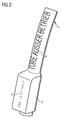
- the cover 1 of Fig. 2 has in addition to the Braille 2 a black letter 8, which also points to the broken door. This can also be carried out in neon writing and / or fluorescent or phosphorescent. As in Fig. 3 to see, are also provided on the rear side in use of the cover 1 characters in braille.
- the cover 1 is slightly curved to enclose a complementarily curved portion of the support rod.
- the cover 1 is here designed to cover a Garmony- or a door opening button. For this purpose, it has a bulge 7. The curvature is independent of the bulge 7. If the support rod in the immediate vicinity of the predetermined section is not steadily gone, the cover 1 is secured against slipping.
- the existing shape of the stop request or door opening button is used for positioning and fixing.
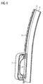
- Fig. 4 the cover 1 is illustrated in the assembled state of use.
- the Haltemony- or door opening button 9 is enclosed here by the bulge 7 of the cover.
Landscapes
- Engineering & Computer Science (AREA)
- Mechanical Engineering (AREA)
- Transportation (AREA)
- Educational Administration (AREA)
- Physics & Mathematics (AREA)
- Business, Economics & Management (AREA)
- Health & Medical Sciences (AREA)
- Educational Technology (AREA)
- General Physics & Mathematics (AREA)
- Theoretical Computer Science (AREA)
- General Health & Medical Sciences (AREA)
- Audiology, Speech & Language Pathology (AREA)
- Steps, Ramps, And Handrails (AREA)
- Vehicle Waterproofing, Decoration, And Sanitation Devices (AREA)
Abstract
Description
- Die Erfindung betrifft eine Abdeckung für eine Haltestange eines öffentlichen Verkehrsmittels.
- Beim Ausfall einer Tür eines Busses oder eines Schienenfahrzeugs des öffentlichen Personenverkehrs hat der Fahrer die Möglichkeit, diese außer Betrieb zu setzen und mechanisch abzusperren. Die Mitteilung des Defekts der Tür erfolgt in der Regel über ein Türstörungstransparent oder einem vom Fahrer an der Tür angebrachten Schild. Eine Information für sehbehinderte Fahrgäste ist nicht vorgesehen.
- Aus dem Patent
US 6,854,163 B1 bekannt geworden ist auch eine Abdeckung für eine Haltestange eines öffentlichen Verkehrsmittels, welche ausgebildet ist, lösbar mit der Haltestange verbunden zu werden und welche Schriftzeichen in Blindenschrift zur Wiedergabe von Informationen an sehbehinderte Fahrgäste umfasst. - Die Gebrauchsmusterschrift
DE 299 20 776 U1 offenbart einen Haltegriff für Fahrzeuginnenräume.
Der Erfindung liegt die Aufgabe zugrunde, den Komfort für sehbehinderte Fahrgäste zu verbessern. - Gelöst wird die Aufgabe durch den Gegenstand des unabhängigen Patentanspruchs 1. Weiterbildungen und Ausgestaltungen der Erfindung finden sich in den Merkmalen der abhängigen Patentansprüche wieder.
- Eine erfindungsgemäße Abdeckung für eine Haltestange eines öffentlichen Verkehrsmittels, beispielsweise eines Busses oder einer Straßenbahn, ist ausgebildet, lösbar mit der Haltestange verbunden zu werden und umfasst Schriftzeichen in Blindenschrift zur Wiedergabe von Informationen an sehbehinderte Fahrgäste.
- Die Schriftzeichen in Blindenschrift zeigen insbesondere einen Defekt einer Tür und/oder den Weg zu einer benachbarten Tür an.
- Als Blindenschrift bezeichnet man eine Schrift, die von Blinden gelesen werden kann. Das Lesen erfolgt dabei mit dem Tastsinn der Finger. Die Schrift ist gegenüber dem Untergrund erhaben oder als Inschrift bzw. Gravur ausgeführt. Weit verbreitet ist die sogenannte Brailleschrift. Jedoch auch andere Arten von Blindenschrift sind bekannt.
- Erfindungsgemäß umfasst die Abdeckung zwei Halbschalen, die einen zueinander komplementären Rastmechanismus aufweisen, um die Halbschalen unter zumindest abschnittsweise umschlossener Haltestange lösbar miteinander zu verschließen.
- Die Abdeckung ist in Längsrichtung zweigeteilt. Die Halbschalen lassen sich um einen vorgegeben Abschnitt der Haltestange legen und mittels des Rastmechanismus an diesem befestigen, indem die Abdeckung den vorgegeben Abschnitt der Haltestange umschließt.
- Eine Halbschale alleine fasst also nur einen Teil des vorgegeben Abschnitts der Haltestange ein. Eine der Halbschalen wird um den vorgegeben Abschnitt der Haltestange gelegt und mit Einrasten der anderen Halbschale an der Haltestange befestigt. Dabei wird die Haltestange dann radial von der geschlossenen Abdeckung umschlossen. Der vorgegebene Abschnitt der Haltestange wird insbesondere vollständig umschlossen. Insbesondere wird der vorgegebene Abschnitt der Haltestange zwischen die Halbschalen geklemmt.
- Um ortsfest mit der Haltestange verbunden zu werden, und somit gegen Verschieben entlang der Haltestange an dieser fixiert zu sein, sind mehrere Ausführungen denkbar. So könnte einerseits die Abdeckung eine hohe Klemmkraft auf die Haltestange ausüben und einen hohen Reibungskoeffizienten zur Haltestange aufweisen. Dazu ist die der Haltestange zugewandte Oberfläche der Abdeckung entsprechend geeignet ausgestaltet. Überdies sind die Werkstoffe der Haltestange und der Abdeckung aufeinander abgestimmt. Zusätzlich oder alternativ sind die einander berührenden Oberflächen von Abdeckung sowie Haltestange aufeinander abgestimmt und so ausgewählt, dass bei einer vorgegebenen Klemmkraft eine vorgegebene Mindestkraft einer Verschiebung der Abdeckung entlang der Haltestange entgegenwirkt. Somit ist die Abdeckung ortsfest mit einer insbesondere rohrförmig und geradlinig verlaufenden Haltestange lösbar zu verbinden.
- Andererseits weist die Haltestange im vorgegeben Abschnitt der Haltestange eine vorgegebene Krümmung auf und Abdeckung ist komplementär zur Haltestange ausgebildet. Die Abdeckung umschließt die Haltestange im Bereich der Krümmung und ist geometrisch gegen Verschiebung gesichert. Insbesondere wenn die unmittelbare Nachbarschaft zum vorgegeben Abschnitt der Haltestange eine andere oder keine Krümmung aufweist. An einem geradlinig ausgebildeten vorgegeben Abschnitt der Haltestange, welcher in unmittelbarer Nachbarschaft einseitig oder beidseitig eine Krümmung aufweist, kann die Abdeckung ebenfalls ortsfest angeordnet werden. Die Abdeckung ist wiederum komplementäre zum vorgegeben Abschnitt der Haltestange, hier also geradlinig, ausgebildet. Die Krümmung der Haltestange in unmittelbarer Nachbarschaft des vorgegeben Abschnitts der Haltestange verhindert ein Verschieben der Abdeckung in Richtung bzw. über die Krümmung.
- Eine weitere Weiterbildung der Erfindung sieht vor, dass die Abdeckung ausgebildet ist, eine Haltewunsch- oder eine Türöffnungstaste abzudecken. Haltewunsch- oder Türöffnungstasten sind üblicherweise auf Haltestangen angeordnet und sind somit Teil der Haltestange.
- Um die Haltewunsch- oder Türöffnungstaste abzudecken kann eine ansonsten rohrförmig ausgebildete Abdeckung eine Ausbuchtung aufweisen, um die Haltewunsch- oder eine Türöffnungstaste abzudecken und gegebenenfalls ebenfalls mit zu umschließen. Wird eine gegenüber der Haltestange erhabene Haltewunsch- oder Türöffnungstaste zumindest teilweise umschlossen, ist die Abdeckung ebenfalls gegen Verschieben gesichert.
- Eine weitere Möglichkeit die Haltewunsch- oder Türöffnungstaste abzudecken besteht darin, dass die Abdeckung eine überstehende Lasche oder Krempe aufweist, die im montierten Gebrauchszustand der Abdeckung über die Haltewunsch- oder Türöffnungstaste ragt und diese somit abdeckt.
- Die Abdeckung ist weitergebildet mittels eines additiven Fertigungsverfahren hergestellt. Das Aufbringen der Blindenschrift kann somit im Fertigungsprozess integriert sein.
- Die Abdeckung kann die Informationen in Blindenschrift auch in Schwarzschrift aufweisen. Weitergebildet trägt die Abdeckung eine Beschriftung in Leuchtschrift, die insbesondere fluoreszierend oder phosphoreszierend ist, damit sie für sehende Fahrgäste auch im Dunkeln sichtbar ist.
- Ein erfindungsgemäßes Fahrzeug des öffentlichen Personenverkehrs umfasst wenigstens eine erfindungsgemäße Abdeckung.
- Diese ist im Gebrauchszustand mit einer Haltestange des Fahrzeugs lösbar verbunden und weitergebildet so an der Haltestange angeordnet, dass sie eine Haltewunsch- oder eine Türöffnungstaste abdeckt.
- Wie oben bereits ausgeführt, kann die Abdeckung einen vorgegebenen Abschnitt der Haltestange umschließen.
- Dazu ist die Abdeckung weitergebildet komplementär zu einem vorgegebenem Abschnitt der Haltestange ausgebildet. Natürlich ist sie zu dem vorgegebenen Abschnitt der Haltestange komplementär ausgebildet, den sie umschließt.
- Dann ist insbesondere die Abdeckung der äußeren Kontur der Haltstange angepasst, beispielsweise der Innendurchmesser der zumindest teilweise rohrförmigen Abdeckung an den Außendurchmesser der rohrförmigen Haltestange angepasst und auch in Längsrichtung dem Verlauf der Haltestange folgend.
- Ein Verfahren zur Montage einer erfindungsgemäßen Abdeckung ist durch folgende Verfahrensschritte gekennzeichnet:
- Anlegen der ersten Halbschale an den vorgegebenen Abschnitt der Haltestange unter Einfassung eines Teils des vorgegebenen Abschnitt der Haltestange;
- Anlegen der zweiten Halbschale an die erste Halbschale unter Einfassung eines Teils des vorgegebenen Abschnitt der Haltestange;
- Einrasten des Rastmechanismus der ersten und der zweiten Halbschale.
- Die Abdeckung ist werkzeuglos schnell und einfach montierbar, sowie auch demontierbar. Sie ist bedarfsgerecht auszubilden. Soll beispielsweise eine defekte Tür angezeigt werden, wird die Abdeckung vom Fahrer im Bereich der defekten Tür angebracht. Wenn sich nun ein sehbehinderter Fahrgast beim Ausstiegsvorgang an der Haltestange im Bereich der Tür festhält, erfährt er, dass die Türe defekt ist. Durch eine Aufschrift in Schwarzschrift werden auch die übrigen Fahrgäste informiert. Ein zusätzliches Anbringen eines Schilds oder ähnlichem entfällt zudem.
- Die Erfindung lässt zahlreiche Ausführungsformen zu. Sie wird anhand der nachfolgenden Figuren näher erläutert, in denen jeweils ein Ausgestaltungsbeispiel dargestellt ist. Gleiche Elemente in den Figuren sind mit gleichen Bezugszeichen versehen.
- Fig. 1
- zeigt eine erfindungsgemäße Abdeckung schematisch in perspektivischer Ansicht,
- Fig. 2
- zeigt ein weiteres Ausgestaltungsbeispiel einer erfindungsgemäßen Abdeckung mit einer Ausbuchtung zur Abdeckung einer Haltewunsch- oder eine Türöffnungstaste schematisch in perspektivischer Ansicht,
- Fig. 3
- zeigt die Abdeckung gemäß
Fig. 2 aus anderer Perspektive, - Fig. 4
- zeigt die Abdeckung gemäß
Fig. 2 im Schnitt. - In
Fig. 1 ist eine erfindungsgemäße Abdeckung 1 dreidimensional dargestellt. Die Abdeckung 1 umfasst hier zwei Halbschalen 3 und 4. Diese können um einen vorgegeben Abschnitt der Haltestange gelegt werden. - Darüber hinaus bilden die Halbschalen 3 und 4 der Abdeckung 1 einen zueinander komplementären Rastmechanismus aus, um sie miteinander zu verschließen. Der Rastmechanismus ist hier gebildet durch ineinandergreifende, in Längsrichtung verlaufende Nut 5 und Feder 6. Jede der Halbschalen 3 und 4 weist hier zwei gegenüberliegende und entgegen gerichtete Nuten 5 und Federn 6. Die Nuten 5 und Federn 6 der Halbschalen 3 und 4 sind wiederum komplementär zueinander ausgebildet, so dass eine Feder 6 der einen Halbschale 3 in eine Nut 5 der anderen Habschale 4 eingreift und umgekehrt. Da die Nuten 5 und Federn 6 an den jeweiligen Rändern der Halbschalen 3 und 4 angeordnet sind und entgegengesetzt ausgerichtet sind, lassen sich die Halbschalen 3 und 4 aneinander legen und durch eine aufeinander gerichtete Kraft einrasten und somit miteinander verschließen. Hier lässt sich zudem eine Halbschale 3 im Eingriff von Nut 5 und Feder 5 entlang der anderen Halbschale 4 zu dieser verschieben.
- Die Halbschalen 3 und 4 fassen im Gebrauchszustand jeweils einen Teil der Haltestange ein und umschließen diese zusammen radial. Hier ist eine geradlinig verlaufende Abdeckung für einen rohrförmig und ebenfalls geradlinig verlaufenden Abschnitt einer Haltestange skizziert. Um nicht entlang der Haltestange verschoben zu werden, wird diese zwischen die Halbschalen geklemmt.
- Die Abdeckung weist Schriftzeichen in Blindenschrift zur Wiedergabe von Informationen an sehbehinderte Fahrgäste auf. Hier ist eine Brailleschrift 2 auf der Halbschale 3 vorgesehen, die dem Fahrgast eine defekte Tür anzeigt.
- Die Abdeckung 1 der
Fig. 2 weist neben der Brailleschrift 2 eine Schwarzschrift 8 auf, die ebenfalls auf die defekte Tür hinweist. Diese kann auch in Leuchtschrift und/oder fluoreszierend oder phosphoreszierend ausgeführt sein. Wie inFig. 3 zu sehen, sind auch auf der im Gebrauchszustand rückwärtigen Seite der Abdeckung 1 Schriftzeichen in Blindenschrift vorgesehen. - Die Abdeckung 1 ist leicht gekrümmt, um einen komplementär gekrümmten Abschnitt der Haltestange zu umschließen. Darüber hinaus ist die Abdeckung 1 hier ausgebildet, eine Haltewunsch- oder eine Türöffnungstaste abzudecken. Dazu weist sie eine Ausbuchtung 7 auf. Die Krümmung ist unabhängig von der Ausbuchtung 7. Verläuft die Haltestange in unmittelbarer Umgebung des vorgegebenen Abschnitts nicht stetig fort, ist die Abdeckung 1 so gegen verrutschen gesichert. Hier wird zusätzlich die vorhandene Form der Haltewunsch- oder Türöffnungstaste zur Positionierung und Fixierung genutzt.
- In
Fig. 4 ist die Abdeckung 1 im montierten Gebrauchszustand veranschaulicht. Die Haltewunsch- oder Türöffnungstaste 9 wird hier von der Ausbuchtung 7 der Abdeckung umschlossen.
Claims (8)
- Abdeckung (1) für eine Haltestange eines öffentlichen Verkehrsmittels, die ausgebildet ist, lösbar mit der Haltestange verbunden zu werden und die Schriftzeichen (2) in Blindenschrift zur Wiedergabe von Informationen an sehbehinderte Fahrgäste umfasst, dadurch gekennzeichnet, dass sie zwei Halbschalen (3, 4) umfasst, die einen zueinander komplementären Rastmechanismus (5, 6) aufweisen, um die Halbschalen (3, 4) unter Umschließen der Haltestange lösbar miteinander zu verschließen.
- Abdeckung nach Anspruch 1,
dadurch gekennzeichnet, dass
die Halbschalen (3, 4) ausgebildet sind, einen vorgegebenen Abschnitt der Haltestange einzuklemmen. - Abdeckung nach einem der Ansprüche 1 bis 2,
dadurch gekennzeichnet, dass
sie ausgebildet ist, eine Haltewunsch- oder eine Türöffnungstaste (9) abzudecken. - Abdeckung nach einem der Ansprüche 1 bis 3,
dadurch gekennzeichnet, dass
sie mittels eines additiven Fertigungsverfahren herstellbar ist. - Abdeckung nach einem der Ansprüche 1 bis 4,
dadurch gekennzeichnet, dass
die Schriftzeichen (2) in Blindenschrift einen Defekt der Tür und/oder den Weg zur benachbarten Tür anzeigen. - Fahrzeug des öffentlichen Personenverkehrs mit wenigstens einer Abdeckung (1) nach einem der Ansprüche 1 bis 5, wobei die Abdeckung (1) lösbar mit einer Haltestange des Fahrzeugs verbunden ist.
- Fahrzeug nach Anspruch 6,
dadurch gekennzeichnet, dass
die Abdeckung (1) so an der Haltestange angeordnet ist, dass sie eine Haltewunsch- oder eine Türöffnungstaste (9) abdeckt. - Fahrzeug nach einem der Ansprüche 6 oder 7,
dadurch gekennzeichnet, dass
die Abdeckung (1) komplementär zu einem vorgegebenem Abschnitt der Haltestange ausgebildet ist.
Applications Claiming Priority (1)
| Application Number | Priority Date | Filing Date | Title |
|---|---|---|---|
| DE102015215780.6A DE102015215780A1 (de) | 2015-08-19 | 2015-08-19 | Haptische Haltestangenabdeckung |
Publications (2)
| Publication Number | Publication Date |
|---|---|
| EP3132978A1 true EP3132978A1 (de) | 2017-02-22 |
| EP3132978B1 EP3132978B1 (de) | 2019-06-05 |
Family
ID=56263533
Family Applications (1)
| Application Number | Title | Priority Date | Filing Date |
|---|---|---|---|
| EP16175695.2A Active EP3132978B1 (de) | 2015-08-19 | 2016-06-22 | Haptische haltestangenabdeckung |
Country Status (7)
| Country | Link |
|---|---|
| US (1) | US20170053559A1 (de) |
| EP (1) | EP3132978B1 (de) |
| CN (1) | CN206049462U (de) |
| DE (1) | DE102015215780A1 (de) |
| DK (1) | DK3132978T3 (de) |
| ES (1) | ES2744582T3 (de) |
| PT (1) | PT3132978T (de) |
Citations (5)
| Publication number | Priority date | Publication date | Assignee | Title |
|---|---|---|---|---|
| US5065837A (en) * | 1991-02-05 | 1991-11-19 | Szudy Katherine A | Handrail for aiding visually handicapped |
| DE29920776U1 (de) | 1999-11-26 | 2000-01-13 | Utescheny-Endos GmbH, 75059 Zaisenhausen | Haltegriff für Fahrzeuginnenräume |
| US6854163B1 (en) | 2001-06-04 | 2005-02-15 | Bruce M. Ruana | Releasably attachable grip |
| DE102005026836A1 (de) * | 2005-06-10 | 2006-12-21 | Dr.Ing.H.C. F. Porsche Ag | Handgriff für ein Kraftfahrzeug |
| GB2510591A (en) * | 2013-02-07 | 2014-08-13 | Robert Stuart Frederick Stanley | Advertisement Display Holder for Handrails and Poles |
Family Cites Families (24)
| Publication number | Priority date | Publication date | Assignee | Title |
|---|---|---|---|---|
| US378432A (en) | 1888-02-28 | Thomas p | ||
| US3365820A (en) * | 1966-04-04 | 1968-01-30 | James W Fair | Education device |
| US3777336A (en) * | 1972-09-14 | 1973-12-11 | Anson Inc | Button cover |
| US5301443A (en) * | 1990-09-12 | 1994-04-12 | Gori Leon M | Shopping cart handle advertising display device |
| USD378432S (en) * | 1995-10-24 | 1997-03-11 | Coco Raynes | Handrail with a braille insert |
| WO2000043273A2 (en) * | 1999-01-19 | 2000-07-27 | The Volusia Holding Corporation | Labeler for pipes, conduits, tubes, and rods |
| JP3660292B2 (ja) * | 2000-11-02 | 2005-06-15 | 株式会社クネット・ジャパン | 手すり及び手すりの取付構造 |
| US20050060924A1 (en) * | 2003-09-19 | 2005-03-24 | Paul Feucht | Device for attaching an advertising display to a hose |
| US20060101685A1 (en) * | 2004-09-10 | 2006-05-18 | Smith Carl Iii | Substrate with light display |
| US20080110067A1 (en) * | 2004-09-10 | 2008-05-15 | Sun Energy Solar, Inc. | Light Units With Communications Capability |
| US20110221149A1 (en) * | 2005-07-29 | 2011-09-15 | Bryan Eugene Crum | Shopping cart device |
| US20070256341A1 (en) * | 2006-05-03 | 2007-11-08 | Postpal, Llc | Post-mountable media display system |
| US20070261281A1 (en) * | 2006-05-15 | 2007-11-15 | Roberge Mark P | Screen Door Indicator Sign |
| KR100873657B1 (ko) * | 2007-02-08 | 2008-12-11 | 김기룡 | 표지판 어셈블리 |
| DE202007005978U1 (de) * | 2007-04-24 | 2008-08-28 | Sonnendorfer, Horst | Displayelement zum Anbringen von Werbung am Griff eines Einkaufswagens |
| US7934726B1 (en) * | 2007-05-03 | 2011-05-03 | Johnson Michael A | Shopping cart display system |
| US20100031541A1 (en) * | 2008-08-08 | 2010-02-11 | Moyer Kathleen J | Doorbell blocking device |
| US20100095567A1 (en) * | 2008-10-21 | 2010-04-22 | Hang Li | Handle with Advertising Areas |
| BRMU8802555Y1 (pt) * | 2008-11-13 | 2017-06-20 | Ricardo Pacheco Antonio | Improvements introduced in information door for passenger transport vehicles |
| DE102009016383A1 (de) * | 2009-04-04 | 2010-10-07 | Happich Fahrzeug- Und Industrieteile Gmbh | Vorrichtung mit Haltewunschtaste |
| US8387542B2 (en) * | 2010-05-17 | 2013-03-05 | Christian R Ahrens | Ski-chair-lift display apparatus and method |
| US9032653B2 (en) * | 2011-06-29 | 2015-05-19 | Wild August Llc | Display ads for door handles providing multisensory stimuli |
| CN203228705U (zh) * | 2013-04-30 | 2013-10-09 | 杭州科技职业技术学院 | 公交下车按铃系统 |
| KR20150057295A (ko) * | 2013-11-19 | 2015-05-28 | 정다훈 | 버스 정차 손잡이 |
-
2015
- 2015-08-19 DE DE102015215780.6A patent/DE102015215780A1/de not_active Withdrawn
-
2016
- 2016-06-22 PT PT16175695T patent/PT3132978T/pt unknown
- 2016-06-22 EP EP16175695.2A patent/EP3132978B1/de active Active
- 2016-06-22 ES ES16175695T patent/ES2744582T3/es active Active
- 2016-06-22 DK DK16175695.2T patent/DK3132978T3/da active
- 2016-08-17 CN CN201620894611.XU patent/CN206049462U/zh active Active
- 2016-08-19 US US15/241,306 patent/US20170053559A1/en not_active Abandoned
Patent Citations (5)
| Publication number | Priority date | Publication date | Assignee | Title |
|---|---|---|---|---|
| US5065837A (en) * | 1991-02-05 | 1991-11-19 | Szudy Katherine A | Handrail for aiding visually handicapped |
| DE29920776U1 (de) | 1999-11-26 | 2000-01-13 | Utescheny-Endos GmbH, 75059 Zaisenhausen | Haltegriff für Fahrzeuginnenräume |
| US6854163B1 (en) | 2001-06-04 | 2005-02-15 | Bruce M. Ruana | Releasably attachable grip |
| DE102005026836A1 (de) * | 2005-06-10 | 2006-12-21 | Dr.Ing.H.C. F. Porsche Ag | Handgriff für ein Kraftfahrzeug |
| GB2510591A (en) * | 2013-02-07 | 2014-08-13 | Robert Stuart Frederick Stanley | Advertisement Display Holder for Handrails and Poles |
Also Published As
| Publication number | Publication date |
|---|---|
| US20170053559A1 (en) | 2017-02-23 |
| DE102015215780A1 (de) | 2017-02-23 |
| ES2744582T3 (es) | 2020-02-25 |
| PT3132978T (pt) | 2019-06-27 |
| CN206049462U (zh) | 2017-03-29 |
| EP3132978B1 (de) | 2019-06-05 |
| DK3132978T3 (da) | 2019-08-12 |
Similar Documents
| Publication | Publication Date | Title |
|---|---|---|
| DE102016113409A1 (de) | Schiene für einen Sitz eines Kraftfahrzeuges sowie Sitzschienensystem für ein Kraftfahrzeug | |
| DE102011116357A1 (de) | Klemmelement und Befestigungsanordnung mit Klemmelement, sowie Verwendungsverfahren des Klemmelementes | |
| DE202012001760U1 (de) | Kabelführung | |
| DE102016111429A1 (de) | Luftleitvorrichtung für ein Fahrzeug, Fahrzeug mit einer Luftleitvorrichtung und Verfahren zum Betrieb einer Luftleitvorrichtung | |
| EP3049287B1 (de) | Haltevorrichtung für ein tragbares elektronisches gerät in einem kraftfahrzeug | |
| DE102010021032A1 (de) | Anzeigevorrichtung für ein Kraftfahrzeug | |
| DE69405846T2 (de) | Lenksäuleneinheit, insbesondere für ein Kraftfahrzeug | |
| DE102017202522A1 (de) | Befestigungselement zum Befestigen eines Sitzbezuges in einem Einhängekanal einer Sitzstruktur | |
| DE102016124921A1 (de) | Abdeckung für ein Fenster in einem Luftfahrzeug | |
| EP3132978B1 (de) | Haptische haltestangenabdeckung | |
| DE9110191U1 (de) | Kabelmarkierer | |
| DE102019120902A1 (de) | Befestigungssystem eines Sitzes und zugeordnetes Fluggerät | |
| DE102017214198B4 (de) | Anordnung und Verfahren zur begrenzten Verschiebung einer Endrohrblende | |
| CH697729B1 (de) | Halter zur Aufnahme eines auswechselbaren Schildes. | |
| DE102007040007A1 (de) | Lagerung für eine Sonnenblende | |
| DE202014102139U1 (de) | Sitzbezug | |
| DE102021111419A1 (de) | Befestigungselement mit eingriffsüberprüfung | |
| EP3495681B1 (de) | Vorrichtung, insbesondere einlegehilfe, zur gleitlagerschalenmontage | |
| DE102013015882A1 (de) | Vorrichtung zur Übertragung einer bei einem Frontaufprall auf ein Kraftfahrzeug wirkenden Kraft | |
| DE102009016383A1 (de) | Vorrichtung mit Haltewunschtaste | |
| DE202011100685U1 (de) | Stützelement zum Abstützen einer Auspreßvorrichtung im Bereich eines Lagerauges einer Achse | |
| DE102013021768B4 (de) | Dämpfungsvorrichtung für längsverschiebbare und umklappbare Mittelarmlehnen | |
| DE102013018900A1 (de) | Kopfstütze für einen Fahrzeugsitz | |
| DE102012221601A1 (de) | Fahrzeugstruktur für Kofferraumdeckelanbringung | |
| DE102008041780A1 (de) | Überrollschutzsystem für Kraftfahrzeuge |
Legal Events
| Date | Code | Title | Description |
|---|---|---|---|
| PUAI | Public reference made under article 153(3) epc to a published international application that has entered the european phase |
Free format text: ORIGINAL CODE: 0009012 |
|
| STAA | Information on the status of an ep patent application or granted ep patent |
Free format text: STATUS: THE APPLICATION HAS BEEN PUBLISHED |
|
| AK | Designated contracting states |
Kind code of ref document: A1 Designated state(s): AL AT BE BG CH CY CZ DE DK EE ES FI FR GB GR HR HU IE IS IT LI LT LU LV MC MK MT NL NO PL PT RO RS SE SI SK SM TR |
|
| AX | Request for extension of the european patent |
Extension state: BA ME |
|
| STAA | Information on the status of an ep patent application or granted ep patent |
Free format text: STATUS: REQUEST FOR EXAMINATION WAS MADE |
|
| 17P | Request for examination filed |
Effective date: 20170505 |
|
| RBV | Designated contracting states (corrected) |
Designated state(s): AL AT BE BG CH CY CZ DE DK EE ES FI FR GB GR HR HU IE IS IT LI LT LU LV MC MK MT NL NO PL PT RO RS SE SI SK SM TR |
|
| RAP1 | Party data changed (applicant data changed or rights of an application transferred) |
Owner name: SIEMENS AKTIENGESELLSCHAFT |
|
| STAA | Information on the status of an ep patent application or granted ep patent |
Free format text: STATUS: EXAMINATION IS IN PROGRESS |
|
| 17Q | First examination report despatched |
Effective date: 20180301 |
|
| RAP1 | Party data changed (applicant data changed or rights of an application transferred) |
Owner name: SIEMENS MOBILITY GMBH |
|
| GRAP | Despatch of communication of intention to grant a patent |
Free format text: ORIGINAL CODE: EPIDOSNIGR1 |
|
| STAA | Information on the status of an ep patent application or granted ep patent |
Free format text: STATUS: GRANT OF PATENT IS INTENDED |
|
| INTG | Intention to grant announced |
Effective date: 20190125 |
|
| GRAS | Grant fee paid |
Free format text: ORIGINAL CODE: EPIDOSNIGR3 |
|
| GRAA | (expected) grant |
Free format text: ORIGINAL CODE: 0009210 |
|
| STAA | Information on the status of an ep patent application or granted ep patent |
Free format text: STATUS: THE PATENT HAS BEEN GRANTED |
|
| AK | Designated contracting states |
Kind code of ref document: B1 Designated state(s): AL AT BE BG CH CY CZ DE DK EE ES FI FR GB GR HR HU IE IS IT LI LT LU LV MC MK MT NL NO PL PT RO RS SE SI SK SM TR |
|
| REG | Reference to a national code |
Ref country code: GB Ref legal event code: FG4D Free format text: NOT ENGLISH |
|
| REG | Reference to a national code |
Ref country code: CH Ref legal event code: EP Ref country code: CH Ref legal event code: NV Representative=s name: SIEMENS SCHWEIZ AG, CH |
|
| REG | Reference to a national code |
Ref country code: AT Ref legal event code: REF Ref document number: 1139661 Country of ref document: AT Kind code of ref document: T Effective date: 20190615 |
|
| REG | Reference to a national code |
Ref country code: IE Ref legal event code: FG4D Free format text: LANGUAGE OF EP DOCUMENT: GERMAN |
|
| REG | Reference to a national code |
Ref country code: DE Ref legal event code: R096 Ref document number: 502016004888 Country of ref document: DE Ref country code: PT Ref legal event code: SC4A Ref document number: 3132978 Country of ref document: PT Date of ref document: 20190627 Kind code of ref document: T Free format text: AVAILABILITY OF NATIONAL TRANSLATION Effective date: 20190621 |
|
| REG | Reference to a national code |
Ref country code: DK Ref legal event code: T3 Effective date: 20190809 |
|
| REG | Reference to a national code |
Ref country code: SE Ref legal event code: TRGR |
|
| REG | Reference to a national code |
Ref country code: NL Ref legal event code: FP |
|
| REG | Reference to a national code |
Ref country code: NO Ref legal event code: T2 Effective date: 20190605 |
|
| REG | Reference to a national code |
Ref country code: LT Ref legal event code: MG4D |
|
| PG25 | Lapsed in a contracting state [announced via postgrant information from national office to epo] |
Ref country code: AL Free format text: LAPSE BECAUSE OF FAILURE TO SUBMIT A TRANSLATION OF THE DESCRIPTION OR TO PAY THE FEE WITHIN THE PRESCRIBED TIME-LIMIT Effective date: 20190605 Ref country code: LT Free format text: LAPSE BECAUSE OF FAILURE TO SUBMIT A TRANSLATION OF THE DESCRIPTION OR TO PAY THE FEE WITHIN THE PRESCRIBED TIME-LIMIT Effective date: 20190605 Ref country code: FI Free format text: LAPSE BECAUSE OF FAILURE TO SUBMIT A TRANSLATION OF THE DESCRIPTION OR TO PAY THE FEE WITHIN THE PRESCRIBED TIME-LIMIT Effective date: 20190605 Ref country code: HR Free format text: LAPSE BECAUSE OF FAILURE TO SUBMIT A TRANSLATION OF THE DESCRIPTION OR TO PAY THE FEE WITHIN THE PRESCRIBED TIME-LIMIT Effective date: 20190605 |
|
| PG25 | Lapsed in a contracting state [announced via postgrant information from national office to epo] |
Ref country code: LV Free format text: LAPSE BECAUSE OF FAILURE TO SUBMIT A TRANSLATION OF THE DESCRIPTION OR TO PAY THE FEE WITHIN THE PRESCRIBED TIME-LIMIT Effective date: 20190605 Ref country code: GR Free format text: LAPSE BECAUSE OF FAILURE TO SUBMIT A TRANSLATION OF THE DESCRIPTION OR TO PAY THE FEE WITHIN THE PRESCRIBED TIME-LIMIT Effective date: 20190906 Ref country code: RS Free format text: LAPSE BECAUSE OF FAILURE TO SUBMIT A TRANSLATION OF THE DESCRIPTION OR TO PAY THE FEE WITHIN THE PRESCRIBED TIME-LIMIT Effective date: 20190605 Ref country code: BG Free format text: LAPSE BECAUSE OF FAILURE TO SUBMIT A TRANSLATION OF THE DESCRIPTION OR TO PAY THE FEE WITHIN THE PRESCRIBED TIME-LIMIT Effective date: 20190905 |
|
| PG25 | Lapsed in a contracting state [announced via postgrant information from national office to epo] |
Ref country code: CZ Free format text: LAPSE BECAUSE OF FAILURE TO SUBMIT A TRANSLATION OF THE DESCRIPTION OR TO PAY THE FEE WITHIN THE PRESCRIBED TIME-LIMIT Effective date: 20190605 Ref country code: RO Free format text: LAPSE BECAUSE OF FAILURE TO SUBMIT A TRANSLATION OF THE DESCRIPTION OR TO PAY THE FEE WITHIN THE PRESCRIBED TIME-LIMIT Effective date: 20190605 Ref country code: SK Free format text: LAPSE BECAUSE OF FAILURE TO SUBMIT A TRANSLATION OF THE DESCRIPTION OR TO PAY THE FEE WITHIN THE PRESCRIBED TIME-LIMIT Effective date: 20190605 Ref country code: EE Free format text: LAPSE BECAUSE OF FAILURE TO SUBMIT A TRANSLATION OF THE DESCRIPTION OR TO PAY THE FEE WITHIN THE PRESCRIBED TIME-LIMIT Effective date: 20190605 |
|
| REG | Reference to a national code |
Ref country code: ES Ref legal event code: FG2A Ref document number: 2744582 Country of ref document: ES Kind code of ref document: T3 Effective date: 20200225 |
|
| PG25 | Lapsed in a contracting state [announced via postgrant information from national office to epo] |
Ref country code: IS Free format text: LAPSE BECAUSE OF FAILURE TO SUBMIT A TRANSLATION OF THE DESCRIPTION OR TO PAY THE FEE WITHIN THE PRESCRIBED TIME-LIMIT Effective date: 20191005 Ref country code: SM Free format text: LAPSE BECAUSE OF FAILURE TO SUBMIT A TRANSLATION OF THE DESCRIPTION OR TO PAY THE FEE WITHIN THE PRESCRIBED TIME-LIMIT Effective date: 20190605 |
|
| REG | Reference to a national code |
Ref country code: DE Ref legal event code: R097 Ref document number: 502016004888 Country of ref document: DE |
|
| PG25 | Lapsed in a contracting state [announced via postgrant information from national office to epo] |
Ref country code: MC Free format text: LAPSE BECAUSE OF FAILURE TO SUBMIT A TRANSLATION OF THE DESCRIPTION OR TO PAY THE FEE WITHIN THE PRESCRIBED TIME-LIMIT Effective date: 20190605 Ref country code: TR Free format text: LAPSE BECAUSE OF FAILURE TO SUBMIT A TRANSLATION OF THE DESCRIPTION OR TO PAY THE FEE WITHIN THE PRESCRIBED TIME-LIMIT Effective date: 20190605 |
|
| PLBE | No opposition filed within time limit |
Free format text: ORIGINAL CODE: 0009261 |
|
| STAA | Information on the status of an ep patent application or granted ep patent |
Free format text: STATUS: NO OPPOSITION FILED WITHIN TIME LIMIT |
|
| PG25 | Lapsed in a contracting state [announced via postgrant information from national office to epo] |
Ref country code: IE Free format text: LAPSE BECAUSE OF NON-PAYMENT OF DUE FEES Effective date: 20190622 Ref country code: PL Free format text: LAPSE BECAUSE OF FAILURE TO SUBMIT A TRANSLATION OF THE DESCRIPTION OR TO PAY THE FEE WITHIN THE PRESCRIBED TIME-LIMIT Effective date: 20190605 |
|
| 26N | No opposition filed |
Effective date: 20200306 |
|
| PG25 | Lapsed in a contracting state [announced via postgrant information from national office to epo] |
Ref country code: LU Free format text: LAPSE BECAUSE OF NON-PAYMENT OF DUE FEES Effective date: 20190622 Ref country code: SI Free format text: LAPSE BECAUSE OF FAILURE TO SUBMIT A TRANSLATION OF THE DESCRIPTION OR TO PAY THE FEE WITHIN THE PRESCRIBED TIME-LIMIT Effective date: 20190605 |
|
| PG25 | Lapsed in a contracting state [announced via postgrant information from national office to epo] |
Ref country code: CY Free format text: LAPSE BECAUSE OF FAILURE TO SUBMIT A TRANSLATION OF THE DESCRIPTION OR TO PAY THE FEE WITHIN THE PRESCRIBED TIME-LIMIT Effective date: 20190605 |
|
| PG25 | Lapsed in a contracting state [announced via postgrant information from national office to epo] |
Ref country code: HU Free format text: LAPSE BECAUSE OF FAILURE TO SUBMIT A TRANSLATION OF THE DESCRIPTION OR TO PAY THE FEE WITHIN THE PRESCRIBED TIME-LIMIT; INVALID AB INITIO Effective date: 20160622 Ref country code: MT Free format text: LAPSE BECAUSE OF FAILURE TO SUBMIT A TRANSLATION OF THE DESCRIPTION OR TO PAY THE FEE WITHIN THE PRESCRIBED TIME-LIMIT Effective date: 20190605 |
|
| PG25 | Lapsed in a contracting state [announced via postgrant information from national office to epo] |
Ref country code: MK Free format text: LAPSE BECAUSE OF FAILURE TO SUBMIT A TRANSLATION OF THE DESCRIPTION OR TO PAY THE FEE WITHIN THE PRESCRIBED TIME-LIMIT Effective date: 20190605 |
|
| PGFP | Annual fee paid to national office [announced via postgrant information from national office to epo] |
Ref country code: DK Payment date: 20250625 Year of fee payment: 10 |
|
| PGFP | Annual fee paid to national office [announced via postgrant information from national office to epo] |
Ref country code: NO Payment date: 20250606 Year of fee payment: 10 |
|
| PGFP | Annual fee paid to national office [announced via postgrant information from national office to epo] |
Ref country code: NL Payment date: 20250610 Year of fee payment: 10 Ref country code: BE Payment date: 20250618 Year of fee payment: 10 |
|
| PGFP | Annual fee paid to national office [announced via postgrant information from national office to epo] |
Ref country code: PT Payment date: 20250514 Year of fee payment: 10 |
|
| PGFP | Annual fee paid to national office [announced via postgrant information from national office to epo] |
Ref country code: FR Payment date: 20250613 Year of fee payment: 10 |
|
| PGFP | Annual fee paid to national office [announced via postgrant information from national office to epo] |
Ref country code: AT Payment date: 20250509 Year of fee payment: 10 |
|
| PGFP | Annual fee paid to national office [announced via postgrant information from national office to epo] |
Ref country code: SE Payment date: 20250605 Year of fee payment: 10 |
|
| REG | Reference to a national code |
Ref country code: DE Ref legal event code: R081 Ref document number: 502016004888 Country of ref document: DE Owner name: SIEMENS MOBILITY GMBH, DE Free format text: FORMER OWNER: SIEMENS MOBILITY GMBH, 81739 MUENCHEN, DE |
|
| PGFP | Annual fee paid to national office [announced via postgrant information from national office to epo] |
Ref country code: ES Payment date: 20250923 Year of fee payment: 10 |
|
| PGFP | Annual fee paid to national office [announced via postgrant information from national office to epo] |
Ref country code: DE Payment date: 20250820 Year of fee payment: 10 |
|
| PGFP | Annual fee paid to national office [announced via postgrant information from national office to epo] |
Ref country code: IT Payment date: 20250625 Year of fee payment: 10 |
|
| PGFP | Annual fee paid to national office [announced via postgrant information from national office to epo] |
Ref country code: GB Payment date: 20250710 Year of fee payment: 10 |
|
| PGFP | Annual fee paid to national office [announced via postgrant information from national office to epo] |
Ref country code: CH Payment date: 20250903 Year of fee payment: 10 |