EP3132901A1 - Dispositif et procede destines au revetement de pieces a usiner - Google Patents
Dispositif et procede destines au revetement de pieces a usiner Download PDFInfo
- Publication number
- EP3132901A1 EP3132901A1 EP16191750.5A EP16191750A EP3132901A1 EP 3132901 A1 EP3132901 A1 EP 3132901A1 EP 16191750 A EP16191750 A EP 16191750A EP 3132901 A1 EP3132901 A1 EP 3132901A1
- Authority
- EP
- European Patent Office
- Prior art keywords
- coating material
- workpiece
- source
- adhesive
- energy
- Prior art date
- Legal status (The legal status is an assumption and is not a legal conclusion. Google has not performed a legal analysis and makes no representation as to the accuracy of the status listed.)
- Granted
Links
- 238000000576 coating method Methods 0.000 title claims abstract description 114
- 239000011248 coating agent Substances 0.000 title claims abstract description 112
- 238000000034 method Methods 0.000 title claims description 19
- 239000000463 material Substances 0.000 claims abstract description 105
- 230000001070 adhesive effect Effects 0.000 claims abstract description 58
- 239000000853 adhesive Substances 0.000 claims abstract description 56
- 238000003825 pressing Methods 0.000 claims abstract description 24
- 239000002023 wood Substances 0.000 claims abstract description 16
- 239000004033 plastic Substances 0.000 claims abstract description 8
- 238000003958 fumigation Methods 0.000 claims abstract description 7
- 238000002604 ultrasonography Methods 0.000 claims abstract description 6
- 229910052782 aluminium Inorganic materials 0.000 claims abstract 2
- XAGFODPZIPBFFR-UHFFFAOYSA-N aluminium Chemical compound [Al] XAGFODPZIPBFFR-UHFFFAOYSA-N 0.000 claims abstract 2
- 239000003795 chemical substances by application Substances 0.000 claims description 17
- 239000011111 cardboard Substances 0.000 claims description 3
- 239000002184 metal Substances 0.000 claims description 3
- 229910052751 metal Inorganic materials 0.000 claims description 3
- 239000000123 paper Substances 0.000 claims description 3
- -1 veneer Substances 0.000 claims description 3
- 229920005610 lignin Polymers 0.000 description 18
- 238000011161 development Methods 0.000 description 4
- 230000018109 developmental process Effects 0.000 description 4
- 230000000694 effects Effects 0.000 description 4
- 238000011144 upstream manufacturing Methods 0.000 description 4
- 239000004831 Hot glue Substances 0.000 description 3
- 230000004913 activation Effects 0.000 description 2
- 230000008901 benefit Effects 0.000 description 2
- 238000006243 chemical reaction Methods 0.000 description 2
- 238000004519 manufacturing process Methods 0.000 description 2
- 230000004048 modification Effects 0.000 description 2
- 238000012986 modification Methods 0.000 description 2
- 230000008569 process Effects 0.000 description 2
- 230000003213 activating effect Effects 0.000 description 1
- 230000001464 adherent effect Effects 0.000 description 1
- 230000015572 biosynthetic process Effects 0.000 description 1
- 230000008859 change Effects 0.000 description 1
- 239000011093 chipboard Substances 0.000 description 1
- 238000011109 contamination Methods 0.000 description 1
- 230000001419 dependent effect Effects 0.000 description 1
- 238000005265 energy consumption Methods 0.000 description 1
- 230000010354 integration Effects 0.000 description 1
- 230000007257 malfunction Effects 0.000 description 1
- 230000007246 mechanism Effects 0.000 description 1
- 238000002844 melting Methods 0.000 description 1
- 230000008018 melting Effects 0.000 description 1
- 230000010355 oscillation Effects 0.000 description 1
- 238000012545 processing Methods 0.000 description 1
- 230000005855 radiation Effects 0.000 description 1
- 239000007787 solid Substances 0.000 description 1
- 239000000126 substance Substances 0.000 description 1
- 238000012546 transfer Methods 0.000 description 1
Images
Classifications
-
- B—PERFORMING OPERATIONS; TRANSPORTING
- B27—WORKING OR PRESERVING WOOD OR SIMILAR MATERIAL; NAILING OR STAPLING MACHINES IN GENERAL
- B27D—WORKING VENEER OR PLYWOOD
- B27D5/00—Other working of veneer or plywood specially adapted to veneer or plywood
- B27D5/003—Other working of veneer or plywood specially adapted to veneer or plywood securing a veneer strip to a panel edge
Definitions
- the invention relates to a method and a device for coating workpieces, which are preferably at least partially made of wood, wood materials, plastic or the like.
- edgebanders in the field of furniture and component industry.
- the DE 34 47 592 An edge banding device in which the edge material is fed via a feed device and a hot melt adhesive is applied to the surface of the edge material facing the workpiece. Subsequently, the edge material is pressed by means of a pressure roller to the surface to be coated of the workpiece.
- the inventive method is based on the idea to use the material properties of the workpieces frequently used wood materials or wood-based materials directly for the adhesion of a coating material.
- the inventive method is characterized in that energy is applied to a surface of the workpiece such that in The lignin contained in the material of the workpiece unfolds adhesive properties at least on the surface of the workpiece to be coated.
- the coating material is pressed against a surface of the workpiece, wherein the coating material is at least partially connected to the workpiece using the adhesive properties of the lignin.
- the energy in the context of the present invention can be applied directly or indirectly to the surface of the workpiece. Indirect application of the energy can take place, for example, by reflection or else by other suitable mechanisms.
- the coating material itself as a transfer medium of reflected radiation, heat or other suitable forms of energy. In this way, it becomes possible, for example, simultaneously to allow an energy input into both the coating material and the workpiece surface, so that it can be used if necessary with a single or at least a reduced number of energy sources.
- connection between the coating material and the respective workpiece exclusively by the lignin contained in the workpiece.
- an additional adhesive or adhesively feasible agent is applied to the surface of the workpiece and / or the coating material. This makes it possible to achieve a particularly reliable and high-quality connection, wherein the use of lignin leads in many cases to a greatly reduced amount of adhesive or adhesive agent to be supplied.
- the invention provides an apparatus for coating workpieces according to claim 5.
- the device according to the invention is based on the idea to start at the interface between the coating material and the workpiece and to replace the previously used, preheated hot melt adhesive by novel bonding techniques.
- the invention provides that the device for coating workpieces has at least one energy source for applying energy to an adhesive or adhesively feasible agent, which may be provided independently and / or may be part of the coating material and / or the workpiece.
- an adhesive or adhesively feasible agent which may be provided independently and / or may be part of the coating material and / or the workpiece.
- the energy source can be designed in different ways in the context of the present invention, the term "energy" in the context of the present invention in a broad sense is to be construed. It is provided according to the invention that the at least one energy source is selected from the group consisting of laser, infrared source, ultrasound source, magnetic field source, microwave source, plasma source and fumigation source. This list makes it clear that in addition to classical energy sources and energy sources come into question, apply the energy, for example, by a chemical reaction to the coating material, for example, a source of fumigation.
- the respective energy source can on the one hand activate an agent already present as an adhesive and, on the other hand, also make an agent which does not serve as an adhesive by applying energy, chemical reaction or the like become an adhesive agent. It should also be noted that any source of energy can in principle be used within the scope of the invention.
- a laser enables a particularly goal-oriented and speedy work, while infrared and plasma sources allow a broad-track operation and a good depth effect.
- a magnetic field has a good depth effect.
- a fumigation-based energy source is particularly well-suited for forming a substance having adhesive properties by acting on and reacting with the coating material.
- the coating material is in the context of the present invention preferably in the form of a supply in the Supply device provided, wherein the coating material may be selected in the context of the present invention from a variety of materials. According to one embodiment of the invention, it is preferred that the material of the coating material is selected from the group consisting of plastic, veneer, paper, cardboard, metal and combinations thereof.
- the coating material 12 at least partially has an integral or discrete layer which unfolds adhesive properties by supplying energy.
- this function can be integrated into the edge feed.
- a complete integration of the adhesive or adhesively feasible agent in the coating material allows a very simple and rapid operation of the device according to the invention.
- the formation of the adhesive or adhesively feasible agent as discrete layer, which is connected at an appropriate time with the coating material the advantage of a higher variety of variants, so must in the latter embodiment, even for a variety of types of coating materials only a single discrete layer of a Adhesive or adhesively feasible agent be kept.
- the device can also be advantageous in the context of the present invention for the device to furthermore have at least one adhesive supply device which is set up to apply an agent which is already adhering or can still be attached by applying energy to the coating material and / or workpiece.
- the variety of variants of the device is still further increased, and it can also be used with combinations of different adhesives, so that virtually any coating material can be applied to virtually any workpiece by means of the device according to the invention.
- the device it is particularly preferred for the device to have at least two adhesive agent provision devices which provide different adhesives or adhesively feasible agents from one another.
- the pressing device is set up to apply the coating material to a narrow surface and / or a wide surface of the workpiece.
- the at least one energy source is arranged movable, preferably transversely to the direction of a relative movement between the pressing device and the respective workpiece generated by the conveyor.
- the conveyor may be configured in the context of the present invention in various ways, for example, such that the respective workpiece is provided stationary and one or more components of the device with respect to the workpiece are movable.
- Such stationary machines are characterized by a very small footprint and high variability.
- the conveying device is set up to convey the workpieces in a passage direction, wherein the conveying operation can be continuous or optionally also clocked. In this way, a particularly rapid and trouble-free operation of the device according to the invention with high throughput is achieved.
- the individual structural units of the device according to the invention can in principle be arranged as independent, fixed or movably mounted units. According to one embodiment of the invention, however, it is provided that at least the pressing device and the energy source are combined to form a unit which can be exchanged via an interface in a supply unit such as in the tool holder of a spindle unit.
- a highly variable and flexible device can be created, with which a wide variety of workpieces and feed materials can be processed without providing an excessively large number of components.
- the number of required drive units is reduced by the interchangeability of the unit of pressure device and energy source, since different units on the common supply unit (for example spindle unit) can be driven and supplied.
- the device has a focusing device, which is set up to direct the energy provided by the energy source to selected regions of the adhesive to be activated or to be generated.
- a focusing device which is set up to direct the energy provided by the energy source to selected regions of the adhesive to be activated or to be generated.
- the operation of the device can be easily adapted to different dimensions of the coating material, without modification work on the respective energy source are required. So the effective area can be punctiform or linear, but also be set flat with different dimensions.
- the intensity of the energy applied to the adhesive can also be varied via the focussing device, so that an optimum coating result can be achieved without damaging the coating material.
- the energy source and / or the focusing device are set up to oscillate. As a result, local energy peaks can be avoided, and a uniform coverage of the area to be energized can be effected. It is particularly preferred that the energy source and / or the focusing device are set up to oscillate the faster the faster the relative movement relative to the workpiece.
- the focusing device can in principle direct the energy provided by the energy source to an arbitrary position of the coating material or optionally also of the workpiece or adhesive. According to one embodiment of the invention, however, it is provided that the focusing device is set up to direct the energy provided by the energy source in the region immediately upstream of a pressing region in which the coating material is pressed against a surface of a workpiece. As a result, it is possible to work with a minimum amount of energy, which not only reduces energy consumption but also minimizes potential damage to the energized materials.
- the device further comprises a control device which is adapted to the operation, in particular the power of the power source on the Properties and dimensions of the adhesive or adhesively feasible agent and to adjust the relative speed between the energy source and adhesive.
- a control device which is adapted to the operation, in particular the power of the power source on the Properties and dimensions of the adhesive or adhesively feasible agent and to adjust the relative speed between the energy source and adhesive.
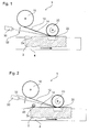
- FIG. 1 A coating apparatus 1 for coating workpieces 2 as a preferred embodiment of the present invention is shown in FIG FIG. 1 schematically shown in a plan view.
- the coating device 1 is used in the present embodiment for coating plate-shaped workpieces 2, which consist at least at intervals of wood-wood materials, plastic or the like, as used for example in the field of furniture and component industry today.
- This can be a variety of workpieces such as solid wood or chipboard, lightweight panels, sandwich panels, skirting, profiles for profile coating etc. It should be noted, however, that the present invention is not limited to such workpieces.
- the coating device 1 initially comprises a conveying device 4, which in the present embodiment is designed as a continuous conveying device, for example in the form of a roller conveyor, belt conveyor or the like.
- the conveyor 4 is used to the workpieces 2 in a direction of passage (from left to right in FIG. 1 ) to promote.
- a feed device 10 for supplying a coating material 12 is arranged, wherein the coating material may be, for example, an edge material for a narrow surface of the workpiece, but also a covering material for a wide surface or any other arbitrary surface of the workpiece 2.
- the feeder 10 contains a supply of coating material 12, which may be made of a variety of materials, such as plastic, veneer, paper, cardboard, metal, etc., and various combinations thereof.
- the coating material may be provided, for example, in roll form (possibly in a cassette), but also in the form of individual sections.
- such integral coating material may be formed, for example, by a plastic material containing a layer 14 which exhibits adhesive properties due to the supply of energy.
- the remaining coating material may in principle be made of any material.
- the discrete layer 14 is arranged on the side of the coating material 12 facing the workpiece 2.
- the feeding device 10 feeds the coating material 12 to a pressing device 20 for pressing the coating material 12 against a surface 2 a of the workpiece 2.
- the pressing device 20 is a pressure roller (instead of a pressure roller belts, shoes or the like can be used, for example), which rolls on the surface 2a of the workpiece 2 and in this way the coating material 12 to the surface 2a of the workpiece 2 presses.
- the coating device 1 comprises an energy source 30 for applying energy to the adhesive or adhesively feasible agent 14.
- energy sources such as laser, infrared source, ultrasound source, magnetic field source, microwave source, plasma source, fumigation source, etc All of these energy sources 30 provide energy in directed form and direct it to the adhesive agent 14 which is supplied as an integral or discrete part of the coating material 12.
- This focused energy is as in FIG. 1 represented by a outgoing from the power source 30 line.
- This passes through a focussing device 32, which is set up to direct the energy provided by the energy source 30 to selected regions of the adhesive 14 to be activated or to be taken.
- the energy source 30 can also be arranged at another suitable location in the context of the invention.
- an energy source according to a general embodiment of the invention for example, be integrated in the pressing device and / or the conveyor.
- the focusing device 32 may be a lens. However, it should be noted that depending on the energy source 30 different focusing device 32 may be used, wherein the focusing device may be each set to adjust the spread and, where appropriate, the intensity of the applied energy. In this way, the focusing device 32 directs the energy provided by the energy source 30 into the region immediately upstream of a pressing region 32, in which the coating material 12 is pressed against the surface 2 a of the workpiece 2.
- This operation of the power source 30 and also of the focusing device 32 is controlled by a control device not shown in detail, wherein the control device in particular the performance of the energy source 30 on the properties and dimensions of the adhesive or adhesively feasible means 14 and the relative speed between the energy source 30 and adhesive 14th tunes.
- the control device can also evaluate information from sensors which monitor the operation of the coating device, for example sensors which are arranged in the region of the pressure region 22 and For example, detect the temperature of the applied coating material 12. On the basis of this information, the control device can control not only the energy source 30 but optionally also the focusing device 32.
- the focusing device 32 is arranged in the present embodiment, to oscillate if necessary, for example, in a direction perpendicular to the plane in FIG. 1 .
- An oscillation movement is understood here to mean a vibration having a frequency of, for example, at least 10 Hz (eg 50 Hz).
- the control device ensures that the focusing device oscillates faster, the faster the relative movement relative to the workpiece 2.
- the focusing device 32 in the present embodiment is movable together with the energy source 30, in a direction transverse to the direction of passage of the conveyor 4. This is particularly advantageous for large-scale coating tasks, such as for coating the broad surfaces of workpieces.
- the device 1 according to the invention also makes it possible to use the method according to the invention, in which lignin contained in the respective workpiece 2 is applied to the coating material 12 at the Surface 2a of the workpiece 2 is used.
- the energy source 30 for this purpose for example by means of the focusing device 32, set up and adjusted so that contained in the material of the workpiece 2 lignin at least on the surface to be coated 2a of the Workpiece adhesive properties unfolds. This presupposes, of course, that lignin is contained in the workpiece to be coated, ie that the workpiece at least partially consists of wood, wood-based materials or the like.
- the coating material 12 is pressed against the surface 2a of the workpiece, so that the coating material is bonded to the workpiece using the adhesive properties of the lignin.
- the adhesive effect of the lignin can be combined with the adhesion of a separately supplied agent 14.
- the energy of the energy source 30 can be applied directly to the surface 2a to be coated. Alternatively or additionally, it is also possible to apply the energy, for example, to the coating material 12. This energy can be reflected by the coating material 12, for example, or introduced in the form of residual heat in the surface 2a of the workpiece.
- FIG. 2 schematically shown in a plan view. This is different from the one in FIG. 1 First embodiment shown primarily in that the adhesive or adhesively feasible means 14 is not supplied together with the coating material 12, but by means of an adhesive supply device in the form of an adhesive applicator roll 40 is applied to the surface 2a to be coated of the workpiece 2. Alternatively or additionally, it is of course also possible to apply the adhesive to the coating material 12 through the adhesive agent delivery device 40.
- the thus-applied adhesive 14 is then also activated or generated by energization by means of the energy source 30, again immediately upstream of a pressing region 22.
- the coating apparatus 12 of the present invention may also include other adhesive providing means, such as a second adhesive applicator roll or the like, these different adhesive providing means preferably also providing different adhesives 14 from each other.
- these different adhesive providing means preferably also providing different adhesives 14 from each other.
- FIG. 3 A third preferred embodiment of the coating device 1 according to the invention is shown in FIG. 3 schematically shown in a plan view.
- the adhesive or adhesively feasible agent 14 in Shape of a web material is provided by an adhesive providing device 42.
- This sheet material 14 is fed in synchronism with the coating material 12 in a region between the coating material 12 and the workpiece 2, and then energized and adhered in the region immediately upstream of a pressing portion 22. In this way, at any time a change of the coating material 12 can be done without problems, while always with the same adhesive or adhesively feasible means can be used.
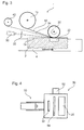
- FIG. 4 A preferred embodiment of the pressing device 20 and the energy source 30 are in FIG. 4 shown schematically in a side view.
- the pressing device 20 and the energy source 30 are combined to form a unit 50, which can be exchanged via an interface 52 in a supply unit such as in the tool holder of a spindle unit.
- the interface 52 may be, for example, a universal interface as described in the patent application EP 0 743 139 the applicant is disclosed.
- the interchangeable unit 50 may also carry the focusing device 32 and also have a feed slot 54 for the coating material so that it can be easily fed to the pressure roller 20 and energized from the opposite side by means of the power source 30 with energy.
- a feed slot 54 for the coating material so that it can be easily fed to the pressure roller 20 and energized from the opposite side by means of the power source 30 with energy.
- an alternative or additional application of energy to the workpiece can take place.
- Such a unit is particularly well suited for stationary machines, but also for continuous machines, and allows a particularly variable and flexible operation
- Such machines the number of required supply units (spindle units) can be reduced accordingly.
Landscapes
- Life Sciences & Earth Sciences (AREA)
- Engineering & Computer Science (AREA)
- Mechanical Engineering (AREA)
- Wood Science & Technology (AREA)
- Forests & Forestry (AREA)
- Application Of Or Painting With Fluid Materials (AREA)
- Coating Apparatus (AREA)
- Adhesives Or Adhesive Processes (AREA)
Applications Claiming Priority (4)
| Application Number | Priority Date | Filing Date | Title |
|---|---|---|---|
| DE202008015878U DE202008015878U1 (de) | 2008-12-01 | 2008-12-01 | Vorrichtung zum Beschichten von Werkstücken |
| EP09002588.3A EP2191947B1 (fr) | 2008-12-01 | 2009-02-24 | Dispositif destinés au revêtement de pièces à usiner |
| EP09763940.5A EP2365899B1 (fr) | 2008-12-01 | 2009-11-30 | Dispositif pour le revêtement de pièces |
| PCT/EP2009/066035 WO2010063668A1 (fr) | 2008-12-01 | 2009-11-30 | Procédé et dispositif pour l'enduction de pièces |
Related Parent Applications (1)
| Application Number | Title | Priority Date | Filing Date |
|---|---|---|---|
| EP09763940.5A Division EP2365899B1 (fr) | 2008-12-01 | 2009-11-30 | Dispositif pour le revêtement de pièces |
Publications (2)
| Publication Number | Publication Date |
|---|---|
| EP3132901A1 true EP3132901A1 (fr) | 2017-02-22 |
| EP3132901B1 EP3132901B1 (fr) | 2019-10-23 |
Family
ID=42105528
Family Applications (3)
| Application Number | Title | Priority Date | Filing Date |
|---|---|---|---|
| EP09002588.3A Expired - Fee Related EP2191947B1 (fr) | 2008-12-01 | 2009-02-24 | Dispositif destinés au revêtement de pièces à usiner |
| EP16191750.5A Active EP3132901B1 (fr) | 2008-12-01 | 2009-11-30 | Dispositif et procede destines au revetement de pieces a usiner |
| EP09763940.5A Active EP2365899B1 (fr) | 2008-12-01 | 2009-11-30 | Dispositif pour le revêtement de pièces |
Family Applications Before (1)
| Application Number | Title | Priority Date | Filing Date |
|---|---|---|---|
| EP09002588.3A Expired - Fee Related EP2191947B1 (fr) | 2008-12-01 | 2009-02-24 | Dispositif destinés au revêtement de pièces à usiner |
Family Applications After (1)
| Application Number | Title | Priority Date | Filing Date |
|---|---|---|---|
| EP09763940.5A Active EP2365899B1 (fr) | 2008-12-01 | 2009-11-30 | Dispositif pour le revêtement de pièces |
Country Status (7)
| Country | Link |
|---|---|
| US (1) | US20120058279A1 (fr) |
| EP (3) | EP2191947B1 (fr) |
| CN (2) | CN102271884A (fr) |
| BR (1) | BRPI0922115A2 (fr) |
| DE (1) | DE202008015878U1 (fr) |
| ES (2) | ES2441599T3 (fr) |
| WO (1) | WO2010063668A1 (fr) |
Cited By (2)
| Publication number | Priority date | Publication date | Assignee | Title |
|---|---|---|---|---|
| DE102018125609A1 (de) * | 2018-10-16 | 2020-04-16 | Surteco Gmbh | Verfahren und Vorrichtung zum Befestigen einer Kantenleiste |
| DE102022113672A1 (de) | 2022-05-31 | 2023-11-30 | Homag Gmbh | Bearbeitungseinrichtung mit einem Beschichtungsaggregat sowie Verfahren zum Applizieren von Haftmittel |
Families Citing this family (19)
| Publication number | Priority date | Publication date | Assignee | Title |
|---|---|---|---|---|
| DE202009019008U1 (de) | 2009-04-22 | 2015-05-27 | Homag Holzbearbeitungssysteme Gmbh | Vorrichtung zum Beschichten von Werkstücken |
| ES2480270T3 (es) | 2010-01-18 | 2014-07-25 | Homag Holzbearbeitungssysteme Ag | Dispositivo y procedimiento para el revestimiento de piezas de trabajo |
| EP2433769B1 (fr) | 2010-09-27 | 2013-04-03 | HOMAG Holzbearbeitungssysteme AG | Dispositif et procédé de revêtement de pièce à usiner |
| CN103124777B (zh) | 2010-09-27 | 2016-08-03 | 汉高股份有限及两合公司 | 利用热熔粘合剂的粘合 |
| DE102012206712A1 (de) * | 2012-04-24 | 2013-10-24 | Homag Holzbearbeitungssysteme Gmbh | Verfahren zur Bearbeitung von Werkstücken |
| DE102013002920B4 (de) | 2013-02-21 | 2018-06-07 | Ima Klessmann Gmbh Holzbearbeitungssysteme | Bekantungsvorrichtung |
| DE102014208519A1 (de) | 2014-05-07 | 2015-11-12 | Homag Holzbearbeitungssysteme Gmbh | Bearbeitungsvorrichtung und Bearbeitungsverfahren |
| DE102015000043A1 (de) | 2015-01-09 | 2016-07-14 | Ima Klessmann Gmbh Holzbearbeitungssysteme | Verfahren zur Bearbeitung von Werkstücken, insbesondere Kantenbändern, und Vorrichtung zur Durchführung des Verfahrens |
| CN107708947A (zh) * | 2015-04-13 | 2018-02-16 | 未来木材工机株式会社 | 木质层积体的制造方法 |
| ITUB20150532A1 (it) | 2015-04-21 | 2016-10-21 | Scm Group Spa | Apparato di bordatura |
| ITUB20152366A1 (it) * | 2015-07-21 | 2017-01-21 | Biesse Spa | Macchina per la bordatura di pannelli di legno o simili |
| DE102017208422A1 (de) * | 2017-05-18 | 2018-11-22 | Homag Gmbh | Bearbeitungsvorrichtung |
| DE102017122701A1 (de) * | 2017-09-29 | 2019-04-04 | Homag Gmbh | Beschichtungsvorrichtung sowie Beschichtungsverfahren |
| US10124536B1 (en) * | 2018-01-08 | 2018-11-13 | Oav Equipment & Tools, Inc. | Edge banding machine |
| DE102019113932A1 (de) * | 2019-05-24 | 2020-11-26 | Homag Gmbh | Verfahren zum Beschichten eines Bauteils sowie Beschichtungsvorrichtung |
| US11660631B2 (en) * | 2021-05-05 | 2023-05-30 | Oav Equipment And Tools, Inc. | Glue applying mechanism of edge banding machine with glue quantity regulator |
| US11541415B2 (en) * | 2021-05-26 | 2023-01-03 | Oav Equipment And Tools, Inc. | Glue applying mechanism of edge banding machine for applying glue to workpiece having oblique surface and edge banding machine using the glue applying mechanism |
| DE102021117813A1 (de) | 2021-07-09 | 2023-01-12 | Homag Gmbh | Verfahren zum Beschichten eines Werkstücks, Beschichtungseinrichtung und Computerprogramm zum Einrichten einer Beschichtungseinrichtung |
| DE102021124866B3 (de) * | 2021-09-27 | 2022-10-20 | Ima Schelling Deutschland Gmbh | Trennvorrichtung, Kantenbearbeitungsvorrichtung und Verfahren zum Durchtrennen eines Beschichtungsmaterials |
Citations (9)
| Publication number | Priority date | Publication date | Assignee | Title |
|---|---|---|---|---|
| US3560297A (en) * | 1966-03-30 | 1971-02-02 | Ernst Ludvig Back | Procedure for sealing together lignocellulosic materials |
| DE3447592A1 (de) | 1984-12-28 | 1986-07-10 | Hornberger Maschinenbaugesellschaft mbH & Co KG, 7294 Schopfloch | Vorrichtung zum auftragen von schmelzkleber auf fortlaufend bewegte werkstuecke |
| US5133822A (en) * | 1989-05-26 | 1992-07-28 | Forestry And Forest Products Research Institute | Process for rapid bonding of lumbers by surface heating |
| EP0743139A1 (fr) | 1995-05-15 | 1996-11-20 | Homag Maschinenbau Ag | Centre d'usinage avec une broche pour porter des outils et des groupes d'outils pour l'usinage de pièces en bois ou matière plastique |
| WO2001036168A1 (fr) * | 1999-11-18 | 2001-05-25 | Brandt Kantentechnik Gmbh | Procede et dispositif pour faire adherer un materiau de recouvrement sur des surfaces de piece en forme de plaques ou de baguettes, se deplaçant en continu ou fixes |
| US20030217807A1 (en) * | 2002-01-25 | 2003-11-27 | Leif Lesmann | Method and apparatus for gluing |
| DE10342723A1 (de) * | 2003-09-16 | 2005-08-04 | Delle Vedove Maschinenbau Gmbh | Wärmetauschervorrichtung |
| EP1800813A2 (fr) * | 2005-11-23 | 2007-06-27 | Technische Universität Dresden | Procédé de revêtement de composants |
| WO2010009805A1 (fr) * | 2008-07-21 | 2010-01-28 | Karl W. Niemann Gmbh & Co. Kg | Procédé d’application de bandes de chant sur les petits côtés de pièces notamment en forme de plaques et pièces obtenues de cette manière |
Family Cites Families (19)
| Publication number | Priority date | Publication date | Assignee | Title |
|---|---|---|---|---|
| DE1085625B (de) * | 1958-02-27 | 1960-07-21 | Mikrowellen Ges M B H Deutsche | Mikrowellenstrahler, vorzugsweise fuer Kantenverleimung |
| SE309900B (fr) * | 1963-09-16 | 1969-04-08 | Svenska Flaektfabriken Ab | |
| US3676283A (en) * | 1969-08-14 | 1972-07-11 | Grace W R & Co | Laminate and process for laminating with polythiol polyene reaction product |
| BE759393A (fr) * | 1970-04-09 | 1971-04-30 | Dhj Ind Inc | Procede et appareil de liaison par application de |
| CN1067399A (zh) * | 1991-06-05 | 1992-12-30 | 蛇口招商无胶人造板新技术有限公司 | 纤维木素原料制造无胶人造板的工业方法及设备 |
| US5607536A (en) * | 1992-10-30 | 1997-03-04 | Tikka-System Oy | Method and apparatus for coating objects with a plastic film |
| US5643983A (en) * | 1995-08-30 | 1997-07-01 | Ashland Inc. | Moisture curable 100% solids one component plywood adhesive |
| DE19742825B4 (de) * | 1997-09-27 | 2010-01-21 | Hohenloher Spezialmöbelwerk Schaffitzel GmbH + Co. | Verfahren zum Aufbringen einer Lineatur und Tafel mit einer Lineatur |
| DE10122573A1 (de) * | 2001-05-09 | 2002-11-14 | Winkler & Duennebier Ag | Klebestation für eine Maschine zum Herstellen von Briefhüllen, Versandbeuteln und dergleichen |
| US7066680B2 (en) * | 2001-12-04 | 2006-06-27 | Integrated Paving Concepts Inc. | Method of forming an inlaid pattern in an asphalt surface |
| KR100448328B1 (ko) * | 2002-03-19 | 2004-09-10 | 이강 | 마이크로웨이브를 이용한 드라이필름 라미네이팅 장치 및방법 |
| AT503091A2 (de) * | 2004-02-04 | 2007-07-15 | Thoma & Harms Holz Gmbh | Verfahren zum verdichten einer oberfläche eines holzwerkstückes und vorrichtung hierzu |
| JP2006231621A (ja) * | 2005-02-23 | 2006-09-07 | Eidai Co Ltd | 突き板貼り化粧材の製造方法とそこで用いられる圧締盤 |
| JP4274573B2 (ja) * | 2006-03-24 | 2009-06-10 | 株式会社森林資源利用促進研究所 | 木製容器及びその製造法 |
| SE529747C2 (sv) * | 2006-04-10 | 2007-11-13 | Carmen Cristescu | Bindemedelfritt förfarande för framställning av lignocellulosalaminat genom varmpressning, samt därigenom framställt laminat |
| DE102006021171A1 (de) | 2006-05-06 | 2007-11-08 | W. Döllken & Co. GmbH | Deckleiste |
| US7494272B2 (en) * | 2006-06-27 | 2009-02-24 | Applied Materials, Inc. | Dynamic surface annealing using addressable laser array with pyrometry feedback |
| EP2168746B1 (fr) * | 2007-06-14 | 2018-04-18 | Aji Co., Ltd. | Procédé et appareil de formage de lentilles non-sphériques |
| DE202007011911U1 (de) * | 2007-08-24 | 2009-01-08 | Rehau Ag + Co | Kantenleiste für Möbelstücke |
-
2008
- 2008-12-01 DE DE202008015878U patent/DE202008015878U1/de not_active Expired - Lifetime
-
2009
- 2009-02-24 EP EP09002588.3A patent/EP2191947B1/fr not_active Expired - Fee Related
- 2009-02-24 ES ES09002588.3T patent/ES2441599T3/es active Active
- 2009-11-30 US US13/132,183 patent/US20120058279A1/en not_active Abandoned
- 2009-11-30 WO PCT/EP2009/066035 patent/WO2010063668A1/fr active Application Filing
- 2009-11-30 ES ES09763940.5T patent/ES2607655T3/es active Active
- 2009-11-30 CN CN200980153888XA patent/CN102271884A/zh active Pending
- 2009-11-30 EP EP16191750.5A patent/EP3132901B1/fr active Active
- 2009-11-30 BR BRPI0922115A patent/BRPI0922115A2/pt not_active Application Discontinuation
- 2009-11-30 EP EP09763940.5A patent/EP2365899B1/fr active Active
- 2009-11-30 CN CN201611051958.9A patent/CN106426431A/zh active Pending
Patent Citations (9)
| Publication number | Priority date | Publication date | Assignee | Title |
|---|---|---|---|---|
| US3560297A (en) * | 1966-03-30 | 1971-02-02 | Ernst Ludvig Back | Procedure for sealing together lignocellulosic materials |
| DE3447592A1 (de) | 1984-12-28 | 1986-07-10 | Hornberger Maschinenbaugesellschaft mbH & Co KG, 7294 Schopfloch | Vorrichtung zum auftragen von schmelzkleber auf fortlaufend bewegte werkstuecke |
| US5133822A (en) * | 1989-05-26 | 1992-07-28 | Forestry And Forest Products Research Institute | Process for rapid bonding of lumbers by surface heating |
| EP0743139A1 (fr) | 1995-05-15 | 1996-11-20 | Homag Maschinenbau Ag | Centre d'usinage avec une broche pour porter des outils et des groupes d'outils pour l'usinage de pièces en bois ou matière plastique |
| WO2001036168A1 (fr) * | 1999-11-18 | 2001-05-25 | Brandt Kantentechnik Gmbh | Procede et dispositif pour faire adherer un materiau de recouvrement sur des surfaces de piece en forme de plaques ou de baguettes, se deplaçant en continu ou fixes |
| US20030217807A1 (en) * | 2002-01-25 | 2003-11-27 | Leif Lesmann | Method and apparatus for gluing |
| DE10342723A1 (de) * | 2003-09-16 | 2005-08-04 | Delle Vedove Maschinenbau Gmbh | Wärmetauschervorrichtung |
| EP1800813A2 (fr) * | 2005-11-23 | 2007-06-27 | Technische Universität Dresden | Procédé de revêtement de composants |
| WO2010009805A1 (fr) * | 2008-07-21 | 2010-01-28 | Karl W. Niemann Gmbh & Co. Kg | Procédé d’application de bandes de chant sur les petits côtés de pièces notamment en forme de plaques et pièces obtenues de cette manière |
Cited By (3)
| Publication number | Priority date | Publication date | Assignee | Title |
|---|---|---|---|---|
| DE102018125609A1 (de) * | 2018-10-16 | 2020-04-16 | Surteco Gmbh | Verfahren und Vorrichtung zum Befestigen einer Kantenleiste |
| DE102018125609B4 (de) | 2018-10-16 | 2021-11-25 | Surteco Gmbh | Verfahren und Vorrichtung zum Befestigen einer Kantenleiste |
| DE102022113672A1 (de) | 2022-05-31 | 2023-11-30 | Homag Gmbh | Bearbeitungseinrichtung mit einem Beschichtungsaggregat sowie Verfahren zum Applizieren von Haftmittel |
Also Published As
| Publication number | Publication date |
|---|---|
| US20120058279A1 (en) | 2012-03-08 |
| BRPI0922115A2 (pt) | 2016-01-05 |
| EP2365899A1 (fr) | 2011-09-21 |
| EP2365899B1 (fr) | 2016-10-12 |
| EP3132901B1 (fr) | 2019-10-23 |
| DE202008015878U1 (de) | 2010-04-15 |
| EP2191947A1 (fr) | 2010-06-02 |
| ES2441599T3 (es) | 2014-02-05 |
| ES2607655T3 (es) | 2017-04-03 |
| CN102271884A (zh) | 2011-12-07 |
| CN106426431A (zh) | 2017-02-22 |
| WO2010063668A1 (fr) | 2010-06-10 |
| EP2191947B1 (fr) | 2013-10-16 |
Similar Documents
| Publication | Publication Date | Title |
|---|---|---|
| EP2191947B1 (fr) | Dispositif destinés au revêtement de pièces à usiner | |
| EP2345518B1 (fr) | Dispositif et procédé destinés au revêtement de pièces à usiner | |
| EP2243619B2 (fr) | Dispositif et procédé destinés au revêtement de pièces à usiner | |
| EP3461608B1 (fr) | Dispositif de revêtement ainsi que procédé de revêtement | |
| EP1800813B1 (fr) | Procédé et dispositif de revêtement de composants | |
| EP2251171B1 (fr) | Dispositif de revêtement de pièces usinées | |
| WO2001089809A1 (fr) | Scellement | |
| EP3075503B1 (fr) | Dispositif et procédé de revêtement | |
| EP3033205B1 (fr) | Unité de revêtement | |
| EP3877124A1 (fr) | Procédé et dispositif pour le revêtement d'une pièce | |
| WO2019038311A1 (fr) | Dispositif pour contre-coller un matériau de revêtement thermoplastique sur un substrat | |
| EP2374587B1 (fr) | Procédé de fabrication de matériau de revêtement | |
| EP1632347A1 (fr) | Méthode et appareil pour relier des matériaux plats | |
| EP3318378B1 (fr) | Procédé de revêtement de surfaces discontinues ainsi qu'élément de construction | |
| WO2018104294A1 (fr) | Dispositif et procédé pour revêtir une pièce | |
| DE3713773C2 (de) | Verfahren und Vorrichtung zum kontinuierlichen Anleimen von Furnierstreifen auf Kanten von plattenförmigen Werkstücken | |
| EP0565752A1 (fr) | Procédé pour l'enduction d'un substrat plan et dispositif pour la mise en oeuvre du procédé | |
| EP3653353B1 (fr) | Dispositif et procédé de revêtement d'une pièce | |
| DE102008024799B4 (de) | Pressvorrichtung sowie Verfahren zum Entfernen von Ablagerungen an einem Presswerkzeug | |
| EP3954515A1 (fr) | Dispositif et procédé de revêtement d'une pièce en forme de plaque | |
| DE102015208172A1 (de) | Beschichtungsmaterial zur Beschichtung unsteter Oberflächen sowie Verfahren | |
| DE102020117025A1 (de) | Vorrichtung und Verfahren zum Beschichten eines Werkstücks | |
| DE19917827A1 (de) | Verfahren und Anlage zur Herstellung von Dekorplatten | |
| DE102005046576A1 (de) | Verfahren und Vorrichtung zur fortlaufenden Aufbringung von Bild-und/oder Folienmaterialien auf Chipkarten |
Legal Events
| Date | Code | Title | Description |
|---|---|---|---|
| PUAI | Public reference made under article 153(3) epc to a published international application that has entered the european phase |
Free format text: ORIGINAL CODE: 0009012 |
|
| STAA | Information on the status of an ep patent application or granted ep patent |
Free format text: STATUS: THE APPLICATION HAS BEEN PUBLISHED |
|
| AC | Divisional application: reference to earlier application |
Ref document number: 2365899 Country of ref document: EP Kind code of ref document: P |
|
| AK | Designated contracting states |
Kind code of ref document: A1 Designated state(s): AT BE BG CH CY CZ DE DK EE ES FI FR GB GR HR HU IE IS IT LI LT LU LV MC MK MT NL NO PL PT RO SE SI SK SM TR |
|
| STAA | Information on the status of an ep patent application or granted ep patent |
Free format text: STATUS: REQUEST FOR EXAMINATION WAS MADE |
|
| 17P | Request for examination filed |
Effective date: 20170529 |
|
| RBV | Designated contracting states (corrected) |
Designated state(s): AT BE BG CH CY CZ DE DK EE ES FI FR GB GR HR HU IE IS IT LI LT LU LV MC MK MT NL NO PL PT RO SE SI SK SM TR |
|
| STAA | Information on the status of an ep patent application or granted ep patent |
Free format text: STATUS: EXAMINATION IS IN PROGRESS |
|
| 17Q | First examination report despatched |
Effective date: 20171201 |
|
| GRAP | Despatch of communication of intention to grant a patent |
Free format text: ORIGINAL CODE: EPIDOSNIGR1 |
|
| STAA | Information on the status of an ep patent application or granted ep patent |
Free format text: STATUS: GRANT OF PATENT IS INTENDED |
|
| INTG | Intention to grant announced |
Effective date: 20190621 |
|
| GRAS | Grant fee paid |
Free format text: ORIGINAL CODE: EPIDOSNIGR3 |
|
| GRAA | (expected) grant |
Free format text: ORIGINAL CODE: 0009210 |
|
| STAA | Information on the status of an ep patent application or granted ep patent |
Free format text: STATUS: THE PATENT HAS BEEN GRANTED |
|
| AC | Divisional application: reference to earlier application |
Ref document number: 2365899 Country of ref document: EP Kind code of ref document: P |
|
| AK | Designated contracting states |
Kind code of ref document: B1 Designated state(s): AT BE BG CH CY CZ DE DK EE ES FI FR GB GR HR HU IE IS IT LI LT LU LV MC MK MT NL NO PL PT RO SE SI SK SM TR |
|
| REG | Reference to a national code |
Ref country code: GB Ref legal event code: FG4D Free format text: NOT ENGLISH |
|
| REG | Reference to a national code |
Ref country code: CH Ref legal event code: EP |
|
| REG | Reference to a national code |
Ref country code: IE Ref legal event code: FG4D Free format text: LANGUAGE OF EP DOCUMENT: GERMAN |
|
| REG | Reference to a national code |
Ref country code: DE Ref legal event code: R096 Ref document number: 502009015998 Country of ref document: DE |
|
| REG | Reference to a national code |
Ref country code: AT Ref legal event code: REF Ref document number: 1193175 Country of ref document: AT Kind code of ref document: T Effective date: 20191115 |
|
| REG | Reference to a national code |
Ref country code: NL Ref legal event code: MP Effective date: 20191023 |
|
| REG | Reference to a national code |
Ref country code: LT Ref legal event code: MG4D |
|
| PG25 | Lapsed in a contracting state [announced via postgrant information from national office to epo] |
Ref country code: NO Free format text: LAPSE BECAUSE OF FAILURE TO SUBMIT A TRANSLATION OF THE DESCRIPTION OR TO PAY THE FEE WITHIN THE PRESCRIBED TIME-LIMIT Effective date: 20200123 Ref country code: PL Free format text: LAPSE BECAUSE OF FAILURE TO SUBMIT A TRANSLATION OF THE DESCRIPTION OR TO PAY THE FEE WITHIN THE PRESCRIBED TIME-LIMIT Effective date: 20191023 Ref country code: GR Free format text: LAPSE BECAUSE OF FAILURE TO SUBMIT A TRANSLATION OF THE DESCRIPTION OR TO PAY THE FEE WITHIN THE PRESCRIBED TIME-LIMIT Effective date: 20200124 Ref country code: LV Free format text: LAPSE BECAUSE OF FAILURE TO SUBMIT A TRANSLATION OF THE DESCRIPTION OR TO PAY THE FEE WITHIN THE PRESCRIBED TIME-LIMIT Effective date: 20191023 Ref country code: SE Free format text: LAPSE BECAUSE OF FAILURE TO SUBMIT A TRANSLATION OF THE DESCRIPTION OR TO PAY THE FEE WITHIN THE PRESCRIBED TIME-LIMIT Effective date: 20191023 Ref country code: BG Free format text: LAPSE BECAUSE OF FAILURE TO SUBMIT A TRANSLATION OF THE DESCRIPTION OR TO PAY THE FEE WITHIN THE PRESCRIBED TIME-LIMIT Effective date: 20200123 Ref country code: FI Free format text: LAPSE BECAUSE OF FAILURE TO SUBMIT A TRANSLATION OF THE DESCRIPTION OR TO PAY THE FEE WITHIN THE PRESCRIBED TIME-LIMIT Effective date: 20191023 Ref country code: PT Free format text: LAPSE BECAUSE OF FAILURE TO SUBMIT A TRANSLATION OF THE DESCRIPTION OR TO PAY THE FEE WITHIN THE PRESCRIBED TIME-LIMIT Effective date: 20200224 Ref country code: NL Free format text: LAPSE BECAUSE OF FAILURE TO SUBMIT A TRANSLATION OF THE DESCRIPTION OR TO PAY THE FEE WITHIN THE PRESCRIBED TIME-LIMIT Effective date: 20191023 Ref country code: LT Free format text: LAPSE BECAUSE OF FAILURE TO SUBMIT A TRANSLATION OF THE DESCRIPTION OR TO PAY THE FEE WITHIN THE PRESCRIBED TIME-LIMIT Effective date: 20191023 |
|
| PG25 | Lapsed in a contracting state [announced via postgrant information from national office to epo] |
Ref country code: HR Free format text: LAPSE BECAUSE OF FAILURE TO SUBMIT A TRANSLATION OF THE DESCRIPTION OR TO PAY THE FEE WITHIN THE PRESCRIBED TIME-LIMIT Effective date: 20191023 Ref country code: IS Free format text: LAPSE BECAUSE OF FAILURE TO SUBMIT A TRANSLATION OF THE DESCRIPTION OR TO PAY THE FEE WITHIN THE PRESCRIBED TIME-LIMIT Effective date: 20200224 |
|
| REG | Reference to a national code |
Ref country code: CH Ref legal event code: PL |
|
| REG | Reference to a national code |
Ref country code: DE Ref legal event code: R097 Ref document number: 502009015998 Country of ref document: DE |
|
| PG2D | Information on lapse in contracting state deleted |
Ref country code: IS |
|
| PG25 | Lapsed in a contracting state [announced via postgrant information from national office to epo] |
Ref country code: MC Free format text: LAPSE BECAUSE OF FAILURE TO SUBMIT A TRANSLATION OF THE DESCRIPTION OR TO PAY THE FEE WITHIN THE PRESCRIBED TIME-LIMIT Effective date: 20191023 Ref country code: ES Free format text: LAPSE BECAUSE OF FAILURE TO SUBMIT A TRANSLATION OF THE DESCRIPTION OR TO PAY THE FEE WITHIN THE PRESCRIBED TIME-LIMIT Effective date: 20191023 Ref country code: CZ Free format text: LAPSE BECAUSE OF FAILURE TO SUBMIT A TRANSLATION OF THE DESCRIPTION OR TO PAY THE FEE WITHIN THE PRESCRIBED TIME-LIMIT Effective date: 20191023 Ref country code: RO Free format text: LAPSE BECAUSE OF FAILURE TO SUBMIT A TRANSLATION OF THE DESCRIPTION OR TO PAY THE FEE WITHIN THE PRESCRIBED TIME-LIMIT Effective date: 20191023 Ref country code: EE Free format text: LAPSE BECAUSE OF FAILURE TO SUBMIT A TRANSLATION OF THE DESCRIPTION OR TO PAY THE FEE WITHIN THE PRESCRIBED TIME-LIMIT Effective date: 20191023 Ref country code: CH Free format text: LAPSE BECAUSE OF NON-PAYMENT OF DUE FEES Effective date: 20191130 Ref country code: DK Free format text: LAPSE BECAUSE OF FAILURE TO SUBMIT A TRANSLATION OF THE DESCRIPTION OR TO PAY THE FEE WITHIN THE PRESCRIBED TIME-LIMIT Effective date: 20191023 Ref country code: LI Free format text: LAPSE BECAUSE OF NON-PAYMENT OF DUE FEES Effective date: 20191130 Ref country code: LU Free format text: LAPSE BECAUSE OF NON-PAYMENT OF DUE FEES Effective date: 20191130 Ref country code: IS Free format text: LAPSE BECAUSE OF FAILURE TO SUBMIT A TRANSLATION OF THE DESCRIPTION OR TO PAY THE FEE WITHIN THE PRESCRIBED TIME-LIMIT Effective date: 20200223 |
|
| REG | Reference to a national code |
Ref country code: BE Ref legal event code: MM Effective date: 20191130 |
|
| PLBE | No opposition filed within time limit |
Free format text: ORIGINAL CODE: 0009261 |
|
| STAA | Information on the status of an ep patent application or granted ep patent |
Free format text: STATUS: NO OPPOSITION FILED WITHIN TIME LIMIT |
|
| PG25 | Lapsed in a contracting state [announced via postgrant information from national office to epo] |
Ref country code: SM Free format text: LAPSE BECAUSE OF FAILURE TO SUBMIT A TRANSLATION OF THE DESCRIPTION OR TO PAY THE FEE WITHIN THE PRESCRIBED TIME-LIMIT Effective date: 20191023 Ref country code: SK Free format text: LAPSE BECAUSE OF FAILURE TO SUBMIT A TRANSLATION OF THE DESCRIPTION OR TO PAY THE FEE WITHIN THE PRESCRIBED TIME-LIMIT Effective date: 20191023 |
|
| GBPC | Gb: european patent ceased through non-payment of renewal fee |
Effective date: 20200123 |
|
| 26N | No opposition filed |
Effective date: 20200724 |
|
| PG25 | Lapsed in a contracting state [announced via postgrant information from national office to epo] |
Ref country code: GB Free format text: LAPSE BECAUSE OF NON-PAYMENT OF DUE FEES Effective date: 20200123 Ref country code: FR Free format text: LAPSE BECAUSE OF NON-PAYMENT OF DUE FEES Effective date: 20191223 Ref country code: IE Free format text: LAPSE BECAUSE OF NON-PAYMENT OF DUE FEES Effective date: 20191130 |
|
| PG25 | Lapsed in a contracting state [announced via postgrant information from national office to epo] |
Ref country code: BE Free format text: LAPSE BECAUSE OF NON-PAYMENT OF DUE FEES Effective date: 20191130 Ref country code: SI Free format text: LAPSE BECAUSE OF FAILURE TO SUBMIT A TRANSLATION OF THE DESCRIPTION OR TO PAY THE FEE WITHIN THE PRESCRIBED TIME-LIMIT Effective date: 20191023 |
|
| PG25 | Lapsed in a contracting state [announced via postgrant information from national office to epo] |
Ref country code: CY Free format text: LAPSE BECAUSE OF FAILURE TO SUBMIT A TRANSLATION OF THE DESCRIPTION OR TO PAY THE FEE WITHIN THE PRESCRIBED TIME-LIMIT Effective date: 20191023 |
|
| PG25 | Lapsed in a contracting state [announced via postgrant information from national office to epo] |
Ref country code: MT Free format text: LAPSE BECAUSE OF FAILURE TO SUBMIT A TRANSLATION OF THE DESCRIPTION OR TO PAY THE FEE WITHIN THE PRESCRIBED TIME-LIMIT Effective date: 20191023 Ref country code: HU Free format text: LAPSE BECAUSE OF FAILURE TO SUBMIT A TRANSLATION OF THE DESCRIPTION OR TO PAY THE FEE WITHIN THE PRESCRIBED TIME-LIMIT; INVALID AB INITIO Effective date: 20091130 |
|
| PG25 | Lapsed in a contracting state [announced via postgrant information from national office to epo] |
Ref country code: TR Free format text: LAPSE BECAUSE OF FAILURE TO SUBMIT A TRANSLATION OF THE DESCRIPTION OR TO PAY THE FEE WITHIN THE PRESCRIBED TIME-LIMIT Effective date: 20191023 |
|
| PG25 | Lapsed in a contracting state [announced via postgrant information from national office to epo] |
Ref country code: MK Free format text: LAPSE BECAUSE OF FAILURE TO SUBMIT A TRANSLATION OF THE DESCRIPTION OR TO PAY THE FEE WITHIN THE PRESCRIBED TIME-LIMIT Effective date: 20191023 |
|
| P01 | Opt-out of the competence of the unified patent court (upc) registered |
Effective date: 20230529 |
|
| PGFP | Annual fee paid to national office [announced via postgrant information from national office to epo] |
Ref country code: IT Payment date: 20231115 Year of fee payment: 15 Ref country code: DE Payment date: 20231106 Year of fee payment: 15 Ref country code: AT Payment date: 20231128 Year of fee payment: 15 |