EP3132886B1 - A tube rotator device and a system for rotating tubes - Google Patents
A tube rotator device and a system for rotating tubes Download PDFInfo
- Publication number
- EP3132886B1 EP3132886B1 EP16184919.5A EP16184919A EP3132886B1 EP 3132886 B1 EP3132886 B1 EP 3132886B1 EP 16184919 A EP16184919 A EP 16184919A EP 3132886 B1 EP3132886 B1 EP 3132886B1
- Authority
- EP
- European Patent Office
- Prior art keywords
- pipe
- rotator
- upper support
- guiding means
- chain
- Prior art date
- Legal status (The legal status is an assumption and is not a legal conclusion. Google has not performed a legal analysis and makes no representation as to the accuracy of the status listed.)
- Active
Links
Images


Classifications
-
- B—PERFORMING OPERATIONS; TRANSPORTING
- B23—MACHINE TOOLS; METAL-WORKING NOT OTHERWISE PROVIDED FOR
- B23K—SOLDERING OR UNSOLDERING; WELDING; CLADDING OR PLATING BY SOLDERING OR WELDING; CUTTING BY APPLYING HEAT LOCALLY, e.g. FLAME CUTTING; WORKING BY LASER BEAM
- B23K31/00—Processes relevant to this subclass, specially adapted for particular articles or purposes, but not covered by any single one of main groups B23K1/00 - B23K28/00
- B23K31/02—Processes relevant to this subclass, specially adapted for particular articles or purposes, but not covered by any single one of main groups B23K1/00 - B23K28/00 relating to soldering or welding
- B23K31/027—Making tubes by soldering or welding
-
- B—PERFORMING OPERATIONS; TRANSPORTING
- B23—MACHINE TOOLS; METAL-WORKING NOT OTHERWISE PROVIDED FOR
- B23K—SOLDERING OR UNSOLDERING; WELDING; CLADDING OR PLATING BY SOLDERING OR WELDING; CUTTING BY APPLYING HEAT LOCALLY, e.g. FLAME CUTTING; WORKING BY LASER BEAM
- B23K37/00—Auxiliary devices or processes, not specially adapted for a procedure covered by only one of the other main groups of this subclass
- B23K37/04—Auxiliary devices or processes, not specially adapted for a procedure covered by only one of the other main groups of this subclass for holding or positioning work
- B23K37/053—Auxiliary devices or processes, not specially adapted for a procedure covered by only one of the other main groups of this subclass for holding or positioning work aligning cylindrical work; Clamping devices therefor
- B23K37/0538—Auxiliary devices or processes, not specially adapted for a procedure covered by only one of the other main groups of this subclass for holding or positioning work aligning cylindrical work; Clamping devices therefor for rotating tubes, e.g. rollers
-
- B—PERFORMING OPERATIONS; TRANSPORTING
- B23—MACHINE TOOLS; METAL-WORKING NOT OTHERWISE PROVIDED FOR
- B23K—SOLDERING OR UNSOLDERING; WELDING; CLADDING OR PLATING BY SOLDERING OR WELDING; CUTTING BY APPLYING HEAT LOCALLY, e.g. FLAME CUTTING; WORKING BY LASER BEAM
- B23K37/00—Auxiliary devices or processes, not specially adapted for a procedure covered by only one of the other main groups of this subclass
- B23K37/04—Auxiliary devices or processes, not specially adapted for a procedure covered by only one of the other main groups of this subclass for holding or positioning work
- B23K37/047—Auxiliary devices or processes, not specially adapted for a procedure covered by only one of the other main groups of this subclass for holding or positioning work moving work to adjust its position between soldering, welding or cutting steps
-
- B—PERFORMING OPERATIONS; TRANSPORTING
- B23—MACHINE TOOLS; METAL-WORKING NOT OTHERWISE PROVIDED FOR
- B23K—SOLDERING OR UNSOLDERING; WELDING; CLADDING OR PLATING BY SOLDERING OR WELDING; CUTTING BY APPLYING HEAT LOCALLY, e.g. FLAME CUTTING; WORKING BY LASER BEAM
- B23K2101/00—Articles made by soldering, welding or cutting
- B23K2101/04—Tubular or hollow articles
- B23K2101/06—Tubes
Definitions
- the invention relates to pipe rotators and to an applicable system according to the preamble of claim 1 (see for example EP 2818273 A1 ).
- pipe rotators are used in pipe processing, such as pipe welding.
- pipe processing such as pipe welding
- pipe rotators are used in industrial pipe welding, for instance, large pipe sizes are rotated by means of bulky and heavy rotators situated beneath the pipe.
- the welders work in different job sites, and, in addition, weld a great variety of objects.
- the heavy and unwieldy pipe rotators are not suitable to these varying uses.
- the welders often use pipe stands as an aid for handling and rotating the pipes. With pipe stands, however, the welders have to rotate the pipe with their hands. It is not rare that small and medium sized pipes still have to be rotated manually. The manual rotation of the pipes makes the welding both slow and difficult. This results in welding inaccuracy and uneven weld quality.
- Today, welding joints have to meet very high quality and standard requirements. The pipes are x-rayed afterwards to assure the weld quality. This requires the welds to be of an especially high quality.
- the welder rotates the pipe with his hands, he always has to interrupt his work and put his tools down for the time period of the rotation of the pipe.
- the work is continually interrupted and it becomes difficult to control the quality of the work.
- the manual rotation also results in an irregular rotational speed.
- the manual rotation also causes a lot of errors at the beginning and at the end of the welding.
- the pipe is supported on the pipe stand by means of a chain, for instance, it becomes hard to rotate the pipe.
- the pipe easily gets scratched by the chain directly contacting the surface of the pipe. It also becomes harder to rotate the pipe if the chain is tightened directly against the surface of the pipe.
- An objective of the present invention is to alleviate the above-mentioned problems encountered in the rotation of pipes.
- the present invention aims at facilitating the rotation of small and medium sized pipes.
- a second objective is to manufacture a device that is easily movable and that can serve as an accessory to the existing pipe stands.
- a third objective is to manufacture a device that reduces the number of errors occurring at the beginning and at the end of welding.
- a fourth objective is to manufacture a pipe rotator that can supported on the pipe to be rotated, preferably by means of a tightenable chain, with the chain not directly contacting the surface of the pipe.
- the pipe rotator of the invention is characterized in what is set forth in the characterizing part of the independent claim 1.
- the pipe rotator of the invention which is connectable to the existing pipe stands, comprises -at least one motorized, pipe rotating roll situated above the pipe.
- the pipe rotator comprises two rotating rolls.
- the rotator comprises a substantially vertical frame and an upper support pivotably connected to the frame, the motorized, pipe rotating roll being connected to the upper support.
- the upper support in its position of use, extends at an angle of substantially 90 degrees to the frame.
- the rotating roll is movable in the longitudinal direction of the upper support.
- the rotator comprises a gas spring, the gas spring being fastened to the frame and the supper support, to pivot the upper support, by the gas spring, to an upper position, from its position of use.
- the gas spring is a pushing gas spring, the gas spring being fastened to the frame and the upper support to pivot the upper support to the upper position by the pushing force of the gas spring.
- the gas spring is a pulling gas spring, the gas spring being fastened to the frame, and to an extension of the upper support, to pivot the upper support to the upper position by the pulling force of the gas spring.
- the rotator comprises a fastening member, the fastening member being fastened to the pipe stand, and the fastening member comprises fastening means to fasten the frame to the fastening member.
- the height of the rotating roll of the rotator is adjustable by moving the frame with respect to the fastening member, and the fastening member comprises quick fasteners to lock the frame at the right height.
- guiding means are provided around the upper support of the rotator, the guiding means being adapted to guide a chain belonging to a chain tightener and running around the upper support.
- the guiding means are guiding rolls.
- the guiding means are (fixed) rods.
- the guiding means are at least two in number.
- the guiding means are three in number.
- one of the guiding means serves as a moving handle for the upper support.
- the guiding means serve as carrying handles for the rotator.
- the rotator comprises a user interface for setting a rotational direction and/or the rotational speed.
- the rotator comprises a foot pedal to start and/or stop the rotating roll.
- the system for rotating a pipe comprises
- the pipe stand is an AMA pipe stand.
- the pipe stand comprises supporting rolls, the pipe to be rotated being rotatable on these supporting rolls.
- the system comprises a chain tightener, the chain tightener being adapted to press the rotating roll against the pipe.
- the pipe stand comprises guiding means, the guiding means guiding the chain of the chain tightener around the supporting rolls, with the chain not contacting the pipe to be rotated.
- the guiding means of the pipe stand are at least two holes in the bottom of the pipe stand.
- guiding means are provided around the upper support of the pipe rotator, the guiding means being adapted to guide the chain of the chain tightener around the upper support.
- the pipe rotator comprises at least two guiding means, the guiding means being fixed rods, or, rotating rolls around the upper support.
- the chain of the chain tightener is provided to extend from below the supporting rolls, through the guiding means of the pipe stand, and around the guiding means of the upper support, thus pressing the rotating roll against the pipe to be rotated.
- a pipe rotator according to an embodiment it is preferred to rotate small and medium sized pipes.
- a pipe rotator according to an embodiment may be easily movable and easily removable from/connectable to any existing pipe (welding) stands.
- a pipe rotator according to an embodiment may allow the rotational direction and the rotational speed to be easily set. It may also be possible, if necessary, to easily move the rotating roll aside from the working area.
- a pipe rotator according to an embodiment may preferably allow the rotating roll to be pressed against the pipe to be rotated.
- the tightenable chain can be adapted not to be directly pressed against the surface of the pipe, and, consequently, not to hinder the rotation of the pipe.
- number refers to any positive integer, starting from one (1), such as to one, two or three.
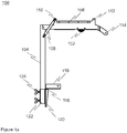
- FIGS 1a and 1b are two perspective views of a pipe rotator according to an embodiment.
- the pipe rotator 100 comprises a motorized, pipe rotating roll 102 situated above the pipe.
- the surface of the roll 102 can be made of wear rubber, for instance.
- the motor rotating the roll is an electric motor.
- the roll 102 can be provided on its own shaft and the electric motor can be adapted to rotate the roll 102 by a toothed belt, for instance.
- the pipe rotator 100 comprises a substantially vertical frame 104.
- the frame can be a hollow steel pipe.
- the pipe rotator also comprises an upper support 106 which usually is pivotally connected to the frame 104. In its position of use, the upper support 106 is substantially horizontal.
- the upper support 106 may comprise a box-shaped structure into which the rotating roll's 102 motor can be fitted.
- the parts of the upper support can be made of steel, plastic or any other suitable material.
- the rotating roll 102 is provided in the upper support, with a part of the rotating roll lower than the bottom of the upper support.
- the pipe rotator 100 comprises a gas spring 108 fastened, at one end, to the frame 104, and, at the other end, to the upper support 106.
- the gas spring attempts to push the upper support from its position of use to an upper position.
- An example of the upper position is that the upper support extends at an angle of substantially 55 degrees to the horizontal.
- the upper support may turn more than 55 degrees, in the upper position, while, in some embodiments, it may turn less than that.
- the gas spring turns the upper support straight upwards, that is, to an angle of 90 degrees, from its position of use.
- Guiding means 110, 112, 114 are provided around the structure of the upper support 106.
- the guiding means can be rolls, or, fixed rods, for instance.
- the guiding means are provided around the structure of the upper support to guide a chain belonging to a chain tightener.
- the guiding means 110, 112, 114 also serve as carrying handles for the pipe rotator.
- the guiding means 110, 112, 114 also serve as a protective structure for the pipe rotator. It is possible that the guiding means are subjected hits as the pipe rotator is moved and handled.
- the guiding means 114 also serves a moving handle for the upper support 106.
- the guiding means 114 allows a user to easily move the upper support to an upper position and/or to its position of use.
- the spring attempts to push the upper support to the upper position.
- the user can push/pull the upper support, by means of the guiding means 114, to its position of use.
- the upper support is automatically moved to the upper position.
- the fastening member 116 comprises two plates 118, 120 substantially perpendicular to each other.
- the upper plate 118 is fastened to a pipe stand by screws, for instance.
- a fastening means such as a hollow mount holder 122, into which the frame 104 of the pipe stand fits, is provided on the lower plate 120.
- the mount holder 122 comprises quick fasteners 124, such as screwable fasteners or locking pins with spring.
- the quick fasteners 124 lock the frame 104 at a desired height.
- the frame 104 may comprise a number of holes receiving the quick fasteners 124 that lock the frame at a given height.
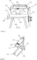
- FIG. 2 shows a pipe rotator 200 according to an embodiment of the present invention, connected to a pipe stand 230.
- the pipe stand 230 comprises supporting rolls 234 situated under the pipe, to allow the pipe to rotate on them.
- the pipe stand also comprises a chain tightener 236.
- the chain 238 of the chain tightener is provided around the upper support 206, the chain keeping the upper support 206 in its position of use.
- the chain 238 is adapted to cause the rotating roll 202 to press against the pipe 232.
- the chain 238 is provided to run from the chain tightener 236, from under the supporting rolls 234, to the frame 204 side.
- the chain is adapted to run, through a bottom hole provided in the pipe stand, around a guiding roll 210, and, further, therefrom, around guiding rolls 212 and 214. Further, the chain is adapted to run, therefrom, through a locking hole provided in the bottom, down to the chain tightener 236.
- the chain tightener creates the pressing force of the pipe rotator 200.
- the above-described pipe stand 230 is called an AMA pipe stand.
- the pipe rotator 200 comprises a foot pedal 240.
- the foot pedal can be wired or wireless. In some embodiments, the foot pedal only has on/off. In some embodiments, the foot pedal allows setting the rotational direction and/or the rotational speed of the rotating roll 202.
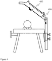
- Figure 3 is a view of a pipe rotator 300 according to an embodiment connected to a pipe stand 330, illustrating holes 350, 352 provided for the chain of the chain tightener.
- the bottom of the pipe stand comprises a guiding hole 350 through which the chain can be pulled up and around the upper support 306.
- the bottom of the pipe stand also comprises a locking hole 352 capable of locking the chain.
- the locking hole 352 comprises oblique cuts where the chain is locked.
- the pipe rotator 300 comprises a user interface 354 from which the rotational direction and/or the rotational speed of the rotating roll 202 can be set.
- the user interface 354 is substantially provided in the front part of the upper support, near a guiding means 314, the guiding means 314 also serving as a moving handle for the upper support.
- the user interface may comprise a number of keys.
- a gas spring 408 provided in a pipe rotator 400 according to an embodiment of the present invention has pushed the upper support 406 from its position of use to an upper position.
- the gas spring 408 is a pushing spring.
- a gas spring 508 provided in a pipe rotator 500 is fastened to the frame 504 and to an extension 507 of the upper support 506, the extension of the upper support extending to the rear of the frame, with respect to the rotating roll.
- the gas spring 508 is a pulling spring whose pulling force has moved the upper support 506 to an upper position.
- the pipe rotator according to the present invention is suitable for rotating pipes of pipe sizes DN25 to DN500.
Landscapes
- Engineering & Computer Science (AREA)
- Mechanical Engineering (AREA)
- Physics & Mathematics (AREA)
- Optics & Photonics (AREA)
- Butt Welding And Welding Of Specific Article (AREA)
- Apparatus For Radiation Diagnosis (AREA)
Applications Claiming Priority (1)
| Application Number | Priority Date | Filing Date | Title |
|---|---|---|---|
| FI20155597A FI127850B (fi) | 2015-08-21 | 2015-08-21 | Putkenpyörittäjälaite ja järjestelmä putken pyörittämiseksi |
Publications (2)
| Publication Number | Publication Date |
|---|---|
| EP3132886A1 EP3132886A1 (en) | 2017-02-22 |
| EP3132886B1 true EP3132886B1 (en) | 2017-11-29 |
Family
ID=56802279
Family Applications (1)
| Application Number | Title | Priority Date | Filing Date |
|---|---|---|---|
| EP16184919.5A Active EP3132886B1 (en) | 2015-08-21 | 2016-08-19 | A tube rotator device and a system for rotating tubes |
Country Status (3)
| Country | Link |
|---|---|
| EP (1) | EP3132886B1 (lt) |
| FI (1) | FI127850B (lt) |
| LT (1) | LT3132886T (lt) |
Cited By (1)
| Publication number | Priority date | Publication date | Assignee | Title |
|---|---|---|---|---|
| FR3148157A1 (fr) * | 2023-04-28 | 2024-11-01 | Monteiro | Machine de soudage pour souder deux pièces tubulaires, dont au moins une est cylindrique |
Families Citing this family (3)
| Publication number | Priority date | Publication date | Assignee | Title |
|---|---|---|---|---|
| US11027381B2 (en) * | 2018-05-03 | 2021-06-08 | Milwaukee Electric Tool Corporation | Pipe rotator assembly |
| WO2021173706A1 (en) * | 2020-02-24 | 2021-09-02 | Rotorweld, Llc | Systems and methods of smart welding operations |
| CN113414537B (zh) * | 2021-06-24 | 2023-03-24 | 江西耐乐科技协同创新有限公司 | 一种方便焊接的超薄异形铜管 |
Family Cites Families (5)
| Publication number | Priority date | Publication date | Assignee | Title |
|---|---|---|---|---|
| US3572199A (en) * | 1969-05-28 | 1971-03-23 | Charles R Harden | Pipe fabricator |
| SE421881B (sv) * | 1979-10-01 | 1982-02-08 | Skutskers Rostfria Ab | Redskap for bearbetning av ror |
| ITTO20030008U1 (it) * | 2003-01-20 | 2003-04-22 | Daniele Comba | Morsa a catena rotativa portatile. |
| WO2012055822A1 (en) * | 2010-10-25 | 2012-05-03 | Rothenberger Ag | Apparatus for cutting and bevelling a plastic pipe |
| EP2818273A1 (de) * | 2013-06-26 | 2014-12-31 | Günes Pili Ltd Sti | Schweißtisch |
-
2015
- 2015-08-21 FI FI20155597A patent/FI127850B/fi not_active IP Right Cessation
-
2016
- 2016-08-19 EP EP16184919.5A patent/EP3132886B1/en active Active
- 2016-08-19 LT LTEP16184919.5T patent/LT3132886T/lt unknown
Non-Patent Citations (1)
| Title |
|---|
| None * |
Cited By (1)
| Publication number | Priority date | Publication date | Assignee | Title |
|---|---|---|---|---|
| FR3148157A1 (fr) * | 2023-04-28 | 2024-11-01 | Monteiro | Machine de soudage pour souder deux pièces tubulaires, dont au moins une est cylindrique |
Also Published As
| Publication number | Publication date |
|---|---|
| FI127850B (fi) | 2019-04-15 |
| LT3132886T (lt) | 2018-03-12 |
| EP3132886A1 (en) | 2017-02-22 |
| FI20155597A7 (fi) | 2017-02-22 |
Similar Documents
| Publication | Publication Date | Title |
|---|---|---|
| EP3132886B1 (en) | A tube rotator device and a system for rotating tubes | |
| US20230294249A1 (en) | Clamping systems for pipes | |
| CN103201056B (zh) | 用于机械加工,特别是用于切割管形或圆形截面体的设备 | |
| EP3313601B1 (en) | Apparatus for manipulating tubular and round section objects | |
| US20150202699A1 (en) | Apparatus for manipulating tubular and round section objects | |
| WO2007082064A2 (en) | Adjustable handle for a concrete saw | |
| EP2601002A1 (en) | Movable work piece clamping mechanism | |
| US5079940A (en) | Roll grooving apparatus | |
| US4075916A (en) | Pipe cut off saw | |
| KR200479394Y1 (ko) | 핸드 그라인더 안전지지대 | |
| CN115415635A (zh) | 一种火焰切割机枪头连接工装 | |
| JPH05169253A (ja) | 手動ガス切断装置 | |
| US4554738A (en) | Apparatus for supporting and guiding machine for operating on sheet material such as cloth | |
| JP2012086503A (ja) | のこぎり補助具 | |
| CN105312727B (zh) | 一种重磅板坡口火焰切割机 | |
| CN211193398U (zh) | 一种具有角度调节结构的管材切割设备 | |
| CN112170951B (zh) | 一种管道多角度的自动环形切割装置 | |
| CN210231718U (zh) | 一种圆锯切割机 | |
| JP4319159B2 (ja) | 鋼管倣い切断装置 | |
| KR20190006361A (ko) | 멀티 커팅장치 | |
| JP7004311B2 (ja) | 溶接ビード切削装置 | |
| US4406090A (en) | Methods and apparatus for grinding spiral tool cutting edges having non-circumferentially relieved edges | |
| JP2005262252A (ja) | トーチの案内装置 | |
| CN219987746U (zh) | 一种板材开料用切割装置 | |
| US4283818A (en) | Apparatus for reducing racket handles |
Legal Events
| Date | Code | Title | Description |
|---|---|---|---|
| PUAI | Public reference made under article 153(3) epc to a published international application that has entered the european phase |
Free format text: ORIGINAL CODE: 0009012 |
|
| 17P | Request for examination filed |
Effective date: 20161128 |
|
| AK | Designated contracting states |
Kind code of ref document: A1 Designated state(s): AL AT BE BG CH CY CZ DE DK EE ES FI FR GB GR HR HU IE IS IT LI LT LU LV MC MK MT NL NO PL PT RO RS SE SI SK SM TR |
|
| AX | Request for extension of the european patent |
Extension state: BA ME |
|
| RIC1 | Information provided on ipc code assigned before grant |
Ipc: B23K 31/02 20060101ALI20170511BHEP Ipc: B23Q 3/06 20060101ALI20170511BHEP Ipc: B23K 37/047 20060101ALI20170511BHEP Ipc: B23K 101/06 20060101ALN20170511BHEP Ipc: B23K 37/053 20060101AFI20170511BHEP |
|
| REG | Reference to a national code |
Ref country code: SE Ref legal event code: TRCL |
|
| GRAP | Despatch of communication of intention to grant a patent |
Free format text: ORIGINAL CODE: EPIDOSNIGR1 |
|
| RIC1 | Information provided on ipc code assigned before grant |
Ipc: B23K 37/047 20060101ALI20170606BHEP Ipc: B23Q 3/06 20060101ALI20170606BHEP Ipc: B23K 101/06 20060101ALN20170606BHEP Ipc: B23K 31/02 20060101ALI20170606BHEP Ipc: B23K 37/053 20060101AFI20170606BHEP |
|
| INTG | Intention to grant announced |
Effective date: 20170707 |
|
| GRAS | Grant fee paid |
Free format text: ORIGINAL CODE: EPIDOSNIGR3 |
|
| GRAA | (expected) grant |
Free format text: ORIGINAL CODE: 0009210 |
|
| AK | Designated contracting states |
Kind code of ref document: B1 Designated state(s): AL AT BE BG CH CY CZ DE DK EE ES FI FR GB GR HR HU IE IS IT LI LT LU LV MC MK MT NL NO PL PT RO RS SE SI SK SM TR |
|
| RAP1 | Party data changed (applicant data changed or rights of an application transferred) |
Owner name: WELNER OY |
|
| REG | Reference to a national code |
Ref country code: CH Ref legal event code: EP |
|
| REG | Reference to a national code |
Ref country code: AT Ref legal event code: REF Ref document number: 949949 Country of ref document: AT Kind code of ref document: T Effective date: 20171215 |
|
| REG | Reference to a national code |
Ref country code: IE Ref legal event code: FG4D |
|
| REG | Reference to a national code |
Ref country code: DE Ref legal event code: R096 Ref document number: 602016000964 Country of ref document: DE |
|
| REG | Reference to a national code |
Ref country code: SE Ref legal event code: TRGR |
|
| REG | Reference to a national code |
Ref country code: NL Ref legal event code: MP Effective date: 20171129 |
|
| REG | Reference to a national code |
Ref country code: AT Ref legal event code: MK05 Ref document number: 949949 Country of ref document: AT Kind code of ref document: T Effective date: 20171129 |
|
| REG | Reference to a national code |
Ref country code: EE Ref legal event code: FG4A Ref document number: E015044 Country of ref document: EE Effective date: 20180220 |
|
| PG25 | Lapsed in a contracting state [announced via postgrant information from national office to epo] |
Ref country code: NO Free format text: LAPSE BECAUSE OF FAILURE TO SUBMIT A TRANSLATION OF THE DESCRIPTION OR TO PAY THE FEE WITHIN THE PRESCRIBED TIME-LIMIT Effective date: 20180228 Ref country code: ES Free format text: LAPSE BECAUSE OF FAILURE TO SUBMIT A TRANSLATION OF THE DESCRIPTION OR TO PAY THE FEE WITHIN THE PRESCRIBED TIME-LIMIT Effective date: 20171129 |
|
| PG25 | Lapsed in a contracting state [announced via postgrant information from national office to epo] |
Ref country code: BG Free format text: LAPSE BECAUSE OF FAILURE TO SUBMIT A TRANSLATION OF THE DESCRIPTION OR TO PAY THE FEE WITHIN THE PRESCRIBED TIME-LIMIT Effective date: 20180228 Ref country code: RS Free format text: LAPSE BECAUSE OF FAILURE TO SUBMIT A TRANSLATION OF THE DESCRIPTION OR TO PAY THE FEE WITHIN THE PRESCRIBED TIME-LIMIT Effective date: 20171129 Ref country code: HR Free format text: LAPSE BECAUSE OF FAILURE TO SUBMIT A TRANSLATION OF THE DESCRIPTION OR TO PAY THE FEE WITHIN THE PRESCRIBED TIME-LIMIT Effective date: 20171129 Ref country code: AT Free format text: LAPSE BECAUSE OF FAILURE TO SUBMIT A TRANSLATION OF THE DESCRIPTION OR TO PAY THE FEE WITHIN THE PRESCRIBED TIME-LIMIT Effective date: 20171129 Ref country code: GR Free format text: LAPSE BECAUSE OF FAILURE TO SUBMIT A TRANSLATION OF THE DESCRIPTION OR TO PAY THE FEE WITHIN THE PRESCRIBED TIME-LIMIT Effective date: 20180301 |
|
| PG25 | Lapsed in a contracting state [announced via postgrant information from national office to epo] |
Ref country code: NL Free format text: LAPSE BECAUSE OF FAILURE TO SUBMIT A TRANSLATION OF THE DESCRIPTION OR TO PAY THE FEE WITHIN THE PRESCRIBED TIME-LIMIT Effective date: 20171129 |
|
| PG25 | Lapsed in a contracting state [announced via postgrant information from national office to epo] |
Ref country code: SK Free format text: LAPSE BECAUSE OF FAILURE TO SUBMIT A TRANSLATION OF THE DESCRIPTION OR TO PAY THE FEE WITHIN THE PRESCRIBED TIME-LIMIT Effective date: 20171129 Ref country code: CY Free format text: LAPSE BECAUSE OF FAILURE TO SUBMIT A TRANSLATION OF THE DESCRIPTION OR TO PAY THE FEE WITHIN THE PRESCRIBED TIME-LIMIT Effective date: 20171129 Ref country code: DK Free format text: LAPSE BECAUSE OF FAILURE TO SUBMIT A TRANSLATION OF THE DESCRIPTION OR TO PAY THE FEE WITHIN THE PRESCRIBED TIME-LIMIT Effective date: 20171129 Ref country code: CZ Free format text: LAPSE BECAUSE OF FAILURE TO SUBMIT A TRANSLATION OF THE DESCRIPTION OR TO PAY THE FEE WITHIN THE PRESCRIBED TIME-LIMIT Effective date: 20171129 |
|
| REG | Reference to a national code |
Ref country code: FR Ref legal event code: PLFP Year of fee payment: 3 |
|
| REG | Reference to a national code |
Ref country code: DE Ref legal event code: R097 Ref document number: 602016000964 Country of ref document: DE |
|
| PG25 | Lapsed in a contracting state [announced via postgrant information from national office to epo] |
Ref country code: SM Free format text: LAPSE BECAUSE OF FAILURE TO SUBMIT A TRANSLATION OF THE DESCRIPTION OR TO PAY THE FEE WITHIN THE PRESCRIBED TIME-LIMIT Effective date: 20171129 Ref country code: PL Free format text: LAPSE BECAUSE OF FAILURE TO SUBMIT A TRANSLATION OF THE DESCRIPTION OR TO PAY THE FEE WITHIN THE PRESCRIBED TIME-LIMIT Effective date: 20171129 Ref country code: IT Free format text: LAPSE BECAUSE OF FAILURE TO SUBMIT A TRANSLATION OF THE DESCRIPTION OR TO PAY THE FEE WITHIN THE PRESCRIBED TIME-LIMIT Effective date: 20171129 Ref country code: RO Free format text: LAPSE BECAUSE OF FAILURE TO SUBMIT A TRANSLATION OF THE DESCRIPTION OR TO PAY THE FEE WITHIN THE PRESCRIBED TIME-LIMIT Effective date: 20171129 |
|
| PLBE | No opposition filed within time limit |
Free format text: ORIGINAL CODE: 0009261 |
|
| STAA | Information on the status of an ep patent application or granted ep patent |
Free format text: STATUS: NO OPPOSITION FILED WITHIN TIME LIMIT |
|
| 26N | No opposition filed |
Effective date: 20180830 |
|
| PG25 | Lapsed in a contracting state [announced via postgrant information from national office to epo] |
Ref country code: MC Free format text: LAPSE BECAUSE OF FAILURE TO SUBMIT A TRANSLATION OF THE DESCRIPTION OR TO PAY THE FEE WITHIN THE PRESCRIBED TIME-LIMIT Effective date: 20171129 |
|
| PG25 | Lapsed in a contracting state [announced via postgrant information from national office to epo] |
Ref country code: LU Free format text: LAPSE BECAUSE OF NON-PAYMENT OF DUE FEES Effective date: 20180819 |
|
| REG | Reference to a national code |
Ref country code: BE Ref legal event code: MM Effective date: 20180831 |
|
| REG | Reference to a national code |
Ref country code: IE Ref legal event code: MM4A |
|
| PG25 | Lapsed in a contracting state [announced via postgrant information from national office to epo] |
Ref country code: IE Free format text: LAPSE BECAUSE OF NON-PAYMENT OF DUE FEES Effective date: 20180819 |
|
| PG25 | Lapsed in a contracting state [announced via postgrant information from national office to epo] |
Ref country code: BE Free format text: LAPSE BECAUSE OF NON-PAYMENT OF DUE FEES Effective date: 20180831 |
|
| PG25 | Lapsed in a contracting state [announced via postgrant information from national office to epo] |
Ref country code: MT Free format text: LAPSE BECAUSE OF NON-PAYMENT OF DUE FEES Effective date: 20180819 |
|
| PG25 | Lapsed in a contracting state [announced via postgrant information from national office to epo] |
Ref country code: TR Free format text: LAPSE BECAUSE OF FAILURE TO SUBMIT A TRANSLATION OF THE DESCRIPTION OR TO PAY THE FEE WITHIN THE PRESCRIBED TIME-LIMIT Effective date: 20171129 |
|
| PG25 | Lapsed in a contracting state [announced via postgrant information from national office to epo] |
Ref country code: CH Free format text: LAPSE BECAUSE OF NON-PAYMENT OF DUE FEES Effective date: 20190831 Ref country code: LI Free format text: LAPSE BECAUSE OF NON-PAYMENT OF DUE FEES Effective date: 20190831 Ref country code: PT Free format text: LAPSE BECAUSE OF FAILURE TO SUBMIT A TRANSLATION OF THE DESCRIPTION OR TO PAY THE FEE WITHIN THE PRESCRIBED TIME-LIMIT Effective date: 20171129 |
|
| PG25 | Lapsed in a contracting state [announced via postgrant information from national office to epo] |
Ref country code: HU Free format text: LAPSE BECAUSE OF FAILURE TO SUBMIT A TRANSLATION OF THE DESCRIPTION OR TO PAY THE FEE WITHIN THE PRESCRIBED TIME-LIMIT; INVALID AB INITIO Effective date: 20160819 Ref country code: MK Free format text: LAPSE BECAUSE OF NON-PAYMENT OF DUE FEES Effective date: 20171129 |
|
| PG25 | Lapsed in a contracting state [announced via postgrant information from national office to epo] |
Ref country code: AL Free format text: LAPSE BECAUSE OF FAILURE TO SUBMIT A TRANSLATION OF THE DESCRIPTION OR TO PAY THE FEE WITHIN THE PRESCRIBED TIME-LIMIT Effective date: 20171129 Ref country code: IS Free format text: LAPSE BECAUSE OF FAILURE TO SUBMIT A TRANSLATION OF THE DESCRIPTION OR TO PAY THE FEE WITHIN THE PRESCRIBED TIME-LIMIT Effective date: 20180329 |
|
| PG25 | Lapsed in a contracting state [announced via postgrant information from national office to epo] |
Ref country code: SI Free format text: LAPSE BECAUSE OF NON-PAYMENT OF DUE FEES Effective date: 20180819 |
|
| REG | Reference to a national code |
Ref country code: EE Ref legal event code: HC1A Ref document number: E015044 Country of ref document: EE |
|
| PGFP | Annual fee paid to national office [announced via postgrant information from national office to epo] |
Ref country code: FI Payment date: 20250820 Year of fee payment: 10 |
|
| PGFP | Annual fee paid to national office [announced via postgrant information from national office to epo] |
Ref country code: LT Payment date: 20250721 Year of fee payment: 10 Ref country code: DE Payment date: 20250819 Year of fee payment: 10 |
|
| PGFP | Annual fee paid to national office [announced via postgrant information from national office to epo] |
Ref country code: GB Payment date: 20250819 Year of fee payment: 10 |
|
| PGFP | Annual fee paid to national office [announced via postgrant information from national office to epo] |
Ref country code: FR Payment date: 20250818 Year of fee payment: 10 |
|
| PGFP | Annual fee paid to national office [announced via postgrant information from national office to epo] |
Ref country code: SE Payment date: 20250819 Year of fee payment: 10 |
|
| PGFP | Annual fee paid to national office [announced via postgrant information from national office to epo] |
Ref country code: EE Payment date: 20250902 Year of fee payment: 10 |
|
| PGFP | Annual fee paid to national office [announced via postgrant information from national office to epo] |
Ref country code: LV Payment date: 20250819 Year of fee payment: 10 |