EP3132859A1 - Dispositif de transport disposant d'une detection de collision - Google Patents
Dispositif de transport disposant d'une detection de collision Download PDFInfo
- Publication number
- EP3132859A1 EP3132859A1 EP16182984.1A EP16182984A EP3132859A1 EP 3132859 A1 EP3132859 A1 EP 3132859A1 EP 16182984 A EP16182984 A EP 16182984A EP 3132859 A1 EP3132859 A1 EP 3132859A1
- Authority
- EP
- European Patent Office
- Prior art keywords
- conveyor
- conveyor unit
- detection
- unit
- longitudinal axis
- Prior art date
- Legal status (The legal status is an assumption and is not a legal conclusion. Google has not performed a legal analysis and makes no representation as to the accuracy of the status listed.)
- Granted
Links
- 238000001514 detection method Methods 0.000 title claims abstract description 118
- 239000000969 carrier Substances 0.000 claims abstract description 6
- 239000007787 solid Substances 0.000 claims abstract description 3
- 239000002800 charge carrier Substances 0.000 description 3
- 230000008878 coupling Effects 0.000 description 3
- 238000010168 coupling process Methods 0.000 description 3
- 238000005859 coupling reaction Methods 0.000 description 3
- 238000000034 method Methods 0.000 description 3
- 239000003973 paint Substances 0.000 description 3
- 230000005540 biological transmission Effects 0.000 description 2
- 230000006835 compression Effects 0.000 description 1
- 238000007906 compression Methods 0.000 description 1
- 238000010276 construction Methods 0.000 description 1
- 230000001419 dependent effect Effects 0.000 description 1
- 230000000694 effects Effects 0.000 description 1
- 230000005670 electromagnetic radiation Effects 0.000 description 1
- 238000007654 immersion Methods 0.000 description 1
- 230000003993 interaction Effects 0.000 description 1
- 238000004519 manufacturing process Methods 0.000 description 1
- 238000000691 measurement method Methods 0.000 description 1
- 230000002265 prevention Effects 0.000 description 1
- 230000011664 signaling Effects 0.000 description 1
Images

Classifications
-
- G—PHYSICS
- G05—CONTROLLING; REGULATING
- G05D—SYSTEMS FOR CONTROLLING OR REGULATING NON-ELECTRIC VARIABLES
- G05D1/00—Control of position, course, altitude or attitude of land, water, air or space vehicles, e.g. using automatic pilots
- G05D1/02—Control of position or course in two dimensions
- G05D1/021—Control of position or course in two dimensions specially adapted to land vehicles
- G05D1/0257—Control of position or course in two dimensions specially adapted to land vehicles using a radar
-
- B—PERFORMING OPERATIONS; TRANSPORTING
- B66—HOISTING; LIFTING; HAULING
- B66F—HOISTING, LIFTING, HAULING OR PUSHING, NOT OTHERWISE PROVIDED FOR, e.g. DEVICES WHICH APPLY A LIFTING OR PUSHING FORCE DIRECTLY TO THE SURFACE OF A LOAD
- B66F9/00—Devices for lifting or lowering bulky or heavy goods for loading or unloading purposes
- B66F9/06—Devices for lifting or lowering bulky or heavy goods for loading or unloading purposes movable, with their loads, on wheels or the like, e.g. fork-lift trucks
- B66F9/063—Automatically guided
-
- G—PHYSICS
- G05—CONTROLLING; REGULATING
- G05D—SYSTEMS FOR CONTROLLING OR REGULATING NON-ELECTRIC VARIABLES
- G05D1/00—Control of position, course, altitude or attitude of land, water, air or space vehicles, e.g. using automatic pilots
- G05D1/02—Control of position or course in two dimensions
- G05D1/021—Control of position or course in two dimensions specially adapted to land vehicles
- G05D1/0287—Control of position or course in two dimensions specially adapted to land vehicles involving a plurality of land vehicles, e.g. fleet or convoy travelling
- G05D1/0291—Fleet control
- G05D1/0293—Convoy travelling
-
- B—PERFORMING OPERATIONS; TRANSPORTING
- B05—SPRAYING OR ATOMISING IN GENERAL; APPLYING FLUENT MATERIALS TO SURFACES, IN GENERAL
- B05B—SPRAYING APPARATUS; ATOMISING APPARATUS; NOZZLES
- B05B14/00—Arrangements for collecting, re-using or eliminating excess spraying material
- B05B14/40—Arrangements for collecting, re-using or eliminating excess spraying material for use in spray booths
- B05B14/43—Arrangements for collecting, re-using or eliminating excess spraying material for use in spray booths by filtering the air charged with excess material
-
- B—PERFORMING OPERATIONS; TRANSPORTING
- B05—SPRAYING OR ATOMISING IN GENERAL; APPLYING FLUENT MATERIALS TO SURFACES, IN GENERAL
- B05B—SPRAYING APPARATUS; ATOMISING APPARATUS; NOZZLES
- B05B16/00—Spray booths
- B05B16/90—Spray booths comprising conveying means for moving objects or other work to be sprayed in and out of the booth, e.g. through the booth
- B05B16/95—Spray booths comprising conveying means for moving objects or other work to be sprayed in and out of the booth, e.g. through the booth the objects or other work to be sprayed lying on, or being held above the conveying means, i.e. not hanging from the conveying means
Definitions
- the invention relates to a conveyor for conveying loaded or unloaded load carriers.
- the conveyor has a first conveyor unit and a second conveyor unit.
- Each conveyor unit has a longitudinal axis and can be moved on floor rollers. At least one of the bottom rollers of a conveyor unit can be driven by means of a drive system.
- the first conveyor unit and the second conveyor unit are movable relative to one another and independently of one another along a respective travel direction at least in the direction of the longitudinal axis.
- the first and the second conveyor unit can move alone and together autonomously, for example, within a warehouse or production hall.
- a conveyor itself is for example from the DE 10 2007 046 868 A1 known.
- two conveyor units each form a conveyor in the manner of a conveyor skid.
- the two skids are designed for conveying load carriers in the form of pallets, in particular of so-called Euro pallets.
- the two skids as a pair of skids run under a pallet, then lift them, promote in the raised state to a place and settle there again.
- the conveyor according to the invention for conveying loaded or unloaded load carriers has a first conveyor unit and a second conveyor unit.
- Each conveyor unit has a longitudinal axis and can be moved on floor rollers. At least one of the bottom rollers of a conveyor unit can be driven by means of a drive system.
- the first conveyor unit and the second conveyor unit are movable relative to one another and independently of one another along a respective travel direction at least in the direction of the longitudinal axis.
- the first conveyor unit and the second conveyor unit each have a radar-based detection device which detects a solid angle range along a detection direction in the direct spatial environment of the respective conveyor unit and the longitudinal axis of a conveyor unit and the detection direction enclose an angle ⁇ 5 °.
- the radar-based detection device is a combined transmitting / receiving device. It actively sends out a radar signal and detects the reception of reflected radar waves.
- the transmission of the radar signal and the reception of the reflected radar waves define a detection direction.
- the design of the components involved in the reception primarily determines the detection direction, but also the emission of the radar signal has an influence on the detection direction of the detection device.
- the angle between the longitudinal axis and the detection direction is between 5 ° and 110 °.
- the angle between the longitudinal axis and the detection direction between 10 ° and 50 ° or between 80 ° and 100 °, more preferably between 20 and 40 ° and in particular at 30 ° or 90 °.
- an angle in the range between 10 ° and 50 °, preferably at 30 ° can improve an improved lateral coverage of the detection area of the detection device.
- a second angle range between 80 ° and 100 °, preferably at 90 °, with a corresponding opening angle with regard to the detection by the detection device can simultaneously enable lateral as well as lateral detection in the direction of travel of the conveyor unit.
- the angle enclosed by the longitudinal axis and the detection direction is arranged parallel to the ground on which the conveyor units move.
- the angular range detected by the detection device is between ⁇ 15 ° and ⁇ 80 °.
- Such an angular range allows the invention Effect with said angles between the longitudinal axis of the conveyor unit and the detection direction.
- the detection device operates on the basis of a continuous wave radar, a phase-modulated pulse radar and / or a frequency-modulated pulse radar.
- the detection device can be arranged on an end of the conveyor unit viewed in the direction of the longitudinal axis.
- the detection device can be arranged on an outer housing section of the conveyor unit extending along the direction of the longitudinal axis. This can make it possible, in particular in the case of a transverse travel of the conveying device, to detect the surroundings in the direction of the transverse traveling direction of the conveying unit.
- a particularly cost-effective embodiment results when the first conveyor unit and the second conveyor unit each have exactly one detection device.
- the detection device of the second conveyor unit may, for example, contribute additional information for adjusting or improving the information obtained.
- the first conveyor unit and the second conveyor unit are oriented in opposite directions with regard to the arrangement of the detection device.
- the detection device of the first conveyor unit in the direction of travel of the entire conveyor detects the environment lying in front of the conveyor, while the detection device of the second conveyor unit in a reversal of the direction of the entire conveyor unit takes over the detection of the environment located in front of the conveyor.
- the respective other detection device can take over the protection of the area behind the conveyor.
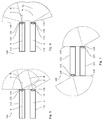
- FIG. 1 shows a schematic plan view of the conveyor 10.
- the conveyor 10 has a first conveyor unit 12 and a second conveyor unit 14. Both conveyor units 12, 14 are each identical in construction and designed as conveyor runners, so that, for example, loaded or unloaded load carriers such as so-called Euro pallets can be driven under.
- FIG. 2 shows a schematic side view of the conveyor of the FIG. 1 ,
- the embodiments of this conveyor unit apply equally to the identical conveyor unit 14.
- the conveyor unit 12 has two bottom rollers 18, 20, of which in this embodiment, only a bottom roller 18 by means of a drive system (not shown) is drivable. However, it is also provided in the context of this invention to carry out both bottom rollers 18, 20 drivable.
- each conveyor unit 12, 14 is primarily along its longitudinal axis A movable.
- the bottom rollers 18, 20 are designed so that direction changes are possible.
- the conveyor units 12, 14 each have a detection device 22, 24.
- the detection means 22, 24 are radar-based, i. the detection of the environment by the detection means 22, 24 employs electromagnetic radiation in the radio range, i. in a frequency range from a few MHz up to several hundred GHz. The exact choice of the frequency range depends on the required resolution and the desired range of the detection system.
- a pulse-based measuring method is used, in which objects can be detected at a distance of up to 50 m and their speed.
- the measurement method can sample the environment at a rate of 30 Hz. It uses the so-called pulse compression method in order to achieve a high resolution with comparatively low transmission power.
- the detection direction B of the detection devices 22, 24 includes with the longitudinal axis A of the conveyor units 12, 14 in the horizontal angle ⁇ .
- the angle ⁇ is in the selected embodiment of the Figures 1-4 30 °. It can be advantageously chosen between 5 ° and 110 °. The exact choice of the angle ⁇ depends on several factors.
- An influencing factor is the detection angle ⁇ of the detection devices 22, 24. In the exemplary embodiment of FIG Figures 1-4 this is 75 °.
- Other influencing variables are the distance of the two conveyor units 12, 14 prevailing during operation of the conveyor 10 as well as the ambient conditions present in the area of use of the conveyor 10.
- the angle ⁇ between the longitudinal axis A of the conveyor units 12, 14 and between the detection direction B is advantageous in comparison to a parallel arrangement: Due to the tilting of the detection direction B, the area lying between the conveyor units 12 and 14 can be detected by the detection device which is in operation is directed inward, to be better grasped. In the embodiment of Figures 1-3 Although this requires the side of the conveyor unit 14 a somewhat limited detection of the environment, but this disadvantage weighs low, since primarily the lying in front of the conveyor in the driving or longitudinal direction surrounding area is of increased relevance.
- a detection device 22 in one direction for example, the current direction of travel
- the other detection device 24 points in the opposite direction.
- This configuration can be achieved for example by a corresponding arrangement of the conveyor units 12, 14.
- a detection device 22 can cover the area lying in front of the conveyor 10 with improved detection of the area lying directly in front of the conveyor, while the other detection device 24 is used only for a reversal of direction for a collision prevention.
- the other detection device 24 can additionally monitor the area behind the conveyor 10 and thus provide additional security.
- FIG. 3 illustrates, in a schematic plan view, the detection area 30 of the detection devices 22, 24 of the conveyor 10 opposite to a detection area 32 which would be formed with a parallel alignment of the detection devices 22, 24 relative to the longitudinal axis A of the conveyor units.
- the detection area 30 extends in a region 34 between the conveyor units 12, 14 closer to the ends 26, 28 of the conveyor units 12, 14, to which the detection means 22, 24 are arranged, so that in this vicinity much better detection done can.
- conveyor 100 of the detection angle ⁇ 150 °.
- FIG. 3 illustrates a simultaneous detection of the environment in front of and behind the conveyor 100.
- FIG. 8 shows a further embodiment of a conveyor 200. Again, all the same or comparable features were referenced by reference numerals, to which 100 and 200 has been added. Such features are not described again to avoid repetition.
- the conveying units 212, 214 have two detection devices:
- the first conveying unit 212 is equipped with two detection devices 222, 223, the second conveying unit 214 with two detection devices 224, 225.
- the detection angles ⁇ of 150 ° and an angle ⁇ of 30 ° between the longitudinal axis A of the conveyor units 212, 214 and the detection direction B it is possible in the in FIG. 8 shown opposing arrangement of the conveyor units 212, 214 on the one hand, depending on the application sufficiently good coverage of the area in front of the conveyor 200 to achieve.
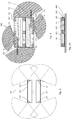
- FIGS. 9 and 10 a fourth embodiment of the invention of a conveyor 300 is shown.
- FIG. 9 shows a schematic, partially sectioned plan view
- FIG. 10 a schematic, partially sectioned side view.
- reference numerals to which 100, 200 or 300 has been added. Such features are not described again to avoid repetition.
- the conveyor 300 comprises two conveyor units 312, 314, each having two detection devices 322, 323 and 324, 325. Unlike the embodiment 200 of the FIG. 7 In each case, a detection device 323, 325 is arranged on a side wall which extends in the direction of the longitudinal axes A of the conveyor units 312, 314. All detection devices 322-325 have a same detection angle, which was selected here with 150 °. Of course, other detection angles and / or combinations are possible, such as different detection angles for the terminal detection unit 322, 324 and for the laterally arranged detection device 323, 325th
- the conveyor is shown below a Euro pallet 400.
- the Euro pallet 400 has free spaces 444, 445 on the outer longitudinal sides, in which the conveyor units 312, 314 retracted and thus can lift the Euro pallet 400.
- the free spaces 444, 445 are defined inter alia by the arrangement of support elements 402, which are in the FIGS. 9 and 10 are shown in a sectional view. For a better representation ability was in the FIGS. 9 and 10 in each case only one of the support elements 402 provided with a reference numeral.
- the lateral detection devices 323, 325 are arranged so that they can detect the corresponding environment from lateral free spaces 440, 442.
- the non-parallel arrangement of detection direction B and transverse conveying direction QFR offers the possibility of at least partially extending the detection field 330, 331 along the respective conveyor unit 312, 314 and thus, for example, during navigation of the conveyor 300 below the load carrier, here the Euro pallet 400 to generate relevant information.
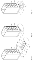
- FIG. 11 shows the conveyor 100 in the approach to a load carrier 40.
- the carrier 40 is in this example fixed to a transported goods 42, here a filter unit for a paint booth, connected.
- the product 42 could also rest loosely on the load carrier or be otherwise connected thereto.
- the detection device 122 it is possible for the conveying device 100 to determine the distance and the size of the load carrier 40 to be traversed.
- the clearances 44, 45 provided for retraction can be detected, suitable retraction parameters for a movement of the conveyor units 112, 114 calculated and approached according to the recognition accuracy of the detection device 122.
- the one detection device 122 of the first conveyor unit 112 is sufficient if, as in this embodiment, a signal-technical coupling of the two conveyor units 112, 114 is realized.
- FIG. 12 shows the state in which the conveyor 100 is completely below the charge carrier 40 and the charge carrier 40 is lifted .
- the detection device 124 Due to the tilting of the detection direction B relative to the longitudinal axis A of the conveyor unit 114, the detection device 124 detects a region which is perpendicular to the longitudinal axis A. and may, for example, detect the complete immersion of the conveyor unit 114 into the free space 44 and transmit a signal to the stop of the conveyor 100 to the controller of the conveyor 100.
- FIG. 13 a situation is shown in which the conveyor 100 already retracted under the load carrier 40, together with the raised load carrier 40, would like to move.
- the planned direction of travel, in FIG. 13 marked with an arrow C, however, is blocked by an object 46 for the entire conveyor 100.
- the detection device 124 of the conveyor unit 114 is able to detect the object 46 as an obstacle, even if it is not directly in front of the charge carrier 40, in order to avoid dangerous situations such as pinch points. Due to the mentioned signaling coupling of the two conveyor units 112, 114, the detection of objects and / or obstacles by a detection device 122, 124 of a conveyor unit 112, 114 is sufficient to supply the entire conveyor 100 with corresponding detection signals for a control. In a single drive of the conveyor units 112, 114, such a coupling can be omitted.
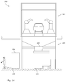
- FIG. 14 shows two applications of such a conveyor 100. It is a paint shop 200 shown, the exact structure for the understanding is not relevant and therefore only roughly outlined.
- the overspray occurring in a paint booth 202 is supplied to a filter system 204 via suitable suction devices and lines.
- the filter system 204 has individual filter units 206, 208.
- a first filter unit 206 which is exhausted in terms of its filter capacity, is lifted by a conveyor 100 and is transported away by the filter system 204.
- the detection device pointing in the direction of travel enables collision and / or obstacle detection for the conveyor 100.
- the non-parallel arrangement of detection direction B and longitudinal axis A ensures detection of obstacles that also lie directly in front of and between the conveyor units 112, 114.
- a second filter unit 208 is being delivered by a conveyor 101 to replace the removed filter unit 208.
- a conveyor 101 can be navigated by the detection means of the conveyor units, possibly supported by a mounted on the conveyor units camera system.
Landscapes
- Engineering & Computer Science (AREA)
- Radar, Positioning & Navigation (AREA)
- Remote Sensing (AREA)
- Automation & Control Theory (AREA)
- General Physics & Mathematics (AREA)
- Physics & Mathematics (AREA)
- Aviation & Aerospace Engineering (AREA)
- Structural Engineering (AREA)
- Transportation (AREA)
- Mechanical Engineering (AREA)
- Geology (AREA)
- Life Sciences & Earth Sciences (AREA)
- Civil Engineering (AREA)
- Control Of Conveyors (AREA)
Applications Claiming Priority (1)
| Application Number | Priority Date | Filing Date | Title |
|---|---|---|---|
| DE102015010718.6A DE102015010718A1 (de) | 2015-08-17 | 2015-08-17 | Fördereinrichtung mit Kollisionsdetektion |
Publications (2)
| Publication Number | Publication Date |
|---|---|
| EP3132859A1 true EP3132859A1 (fr) | 2017-02-22 |
| EP3132859B1 EP3132859B1 (fr) | 2018-10-17 |
Family
ID=56737920
Family Applications (1)
| Application Number | Title | Priority Date | Filing Date |
|---|---|---|---|
| EP16182984.1A Not-in-force EP3132859B1 (fr) | 2015-08-17 | 2016-08-05 | Dispositif de transport disposant d'une detection de collision |
Country Status (2)
| Country | Link |
|---|---|
| EP (1) | EP3132859B1 (fr) |
| DE (1) | DE102015010718A1 (fr) |
Cited By (4)
| Publication number | Priority date | Publication date | Assignee | Title |
|---|---|---|---|---|
| CN109550627A (zh) * | 2018-12-12 | 2019-04-02 | 海宁卡森皮革有限公司 | 一种环保型皮革表面自动喷涂系统 |
| WO2019141339A1 (fr) * | 2018-01-18 | 2019-07-25 | Sew-Eurodrive Gmbh & Co. Kg | Procédé de fonctionnement d'une installation et installation |
| FR3081363A1 (fr) * | 2018-05-28 | 2019-11-29 | Norcan | Robot motorise de transport de charges. |
| EP3786086A1 (fr) * | 2014-08-19 | 2021-03-03 | Harald Schütz | Systèmes de stockage et/ou de préparation de commandes |
Families Citing this family (7)
| Publication number | Priority date | Publication date | Assignee | Title |
|---|---|---|---|---|
| DE102017000676A1 (de) | 2017-01-26 | 2018-07-26 | Uwe Spiekermann | Automatische Hub- und Transporteinrichtung für palettenähnliche Gebinde |
| EP4269320A3 (fr) | 2019-02-15 | 2023-12-06 | Filics GmbH | Dispositif de transport pour porteurs de charge |
| DE102019001125B4 (de) * | 2019-02-15 | 2022-01-20 | FILICS GmbH | Fördereinrichtung für Ladungsträger mit integrierter Kollisionsdetektion |
| DE102019213922A1 (de) | 2019-09-12 | 2021-03-18 | Jungheinrich Aktiengesellschaft | Fahrzeug mit Umfeldüberwachungseinrichtung |
| DE102020207479A1 (de) | 2020-06-17 | 2021-12-23 | Zf Friedrichshafen Ag | Gabelzinkensensoren zur Erkennung von Querverkehr |
| WO2022156952A1 (fr) | 2021-01-21 | 2022-07-28 | Sew-Eurodrive Gmbh & Co. Kg | Véhicule de transport sans conducteur et procédé de fonctionnement d'un véhicule de transport sans conducteur |
| DE102021103799A1 (de) | 2021-02-18 | 2022-08-18 | Jungheinrich Aktiengesellschaft | Flurförderzeug mit erfassungseinrichtungen an gabelzinken |
Citations (5)
| Publication number | Priority date | Publication date | Assignee | Title |
|---|---|---|---|---|
| US4345662A (en) * | 1978-12-06 | 1982-08-24 | Matra | Installation with automatic vehicles |
| US5314037A (en) * | 1993-01-22 | 1994-05-24 | Shaw David C H | Automobile collision avoidance system |
| EP0991045A2 (fr) * | 1998-09-30 | 2000-04-05 | Volkswagen Aktiengesellschaft | Méthode et appareil de détection d'obstacles |
| DE19910715A1 (de) * | 1999-03-10 | 2000-09-21 | Deutsch Zentr Luft & Raumfahrt | Verfahren zum autonomen Führen von Roboterfahrzeugen in Hallen sowie Radarstation zur Durchführung des Verfahrens |
| DE102007046868A1 (de) | 2007-09-28 | 2009-04-16 | Universität Stuttgart | Transportvorrichtung für Ladungsträger und Verfahren zu deren Steuerung |
Family Cites Families (3)
| Publication number | Priority date | Publication date | Assignee | Title |
|---|---|---|---|---|
| DE3004671A1 (de) * | 1980-02-08 | 1981-08-13 | Jungheinrich Unternehmensverwaltung Kg, 2000 Hamburg | Anordnung zur auffahrsicherung und kollisionsschutz an flurfoerderfahrzeugen und flurfoerderfahrzeug mit einer solchen anordnung |
| DE202007016156U1 (de) * | 2007-11-16 | 2008-03-20 | Noell Mobile Systems Gmbh | Portalhubstapler mit automatischer Lenkung |
| DE102013017062A1 (de) * | 2013-10-15 | 2015-04-16 | Eisenmann Ag | Fördereinheit und Fördersystem zum Fördern von Ladungsträgern |
-
2015
- 2015-08-17 DE DE102015010718.6A patent/DE102015010718A1/de not_active Withdrawn
-
2016
- 2016-08-05 EP EP16182984.1A patent/EP3132859B1/fr not_active Not-in-force
Patent Citations (5)
| Publication number | Priority date | Publication date | Assignee | Title |
|---|---|---|---|---|
| US4345662A (en) * | 1978-12-06 | 1982-08-24 | Matra | Installation with automatic vehicles |
| US5314037A (en) * | 1993-01-22 | 1994-05-24 | Shaw David C H | Automobile collision avoidance system |
| EP0991045A2 (fr) * | 1998-09-30 | 2000-04-05 | Volkswagen Aktiengesellschaft | Méthode et appareil de détection d'obstacles |
| DE19910715A1 (de) * | 1999-03-10 | 2000-09-21 | Deutsch Zentr Luft & Raumfahrt | Verfahren zum autonomen Führen von Roboterfahrzeugen in Hallen sowie Radarstation zur Durchführung des Verfahrens |
| DE102007046868A1 (de) | 2007-09-28 | 2009-04-16 | Universität Stuttgart | Transportvorrichtung für Ladungsträger und Verfahren zu deren Steuerung |
Cited By (7)
| Publication number | Priority date | Publication date | Assignee | Title |
|---|---|---|---|---|
| EP3786086A1 (fr) * | 2014-08-19 | 2021-03-03 | Harald Schütz | Systèmes de stockage et/ou de préparation de commandes |
| WO2019141339A1 (fr) * | 2018-01-18 | 2019-07-25 | Sew-Eurodrive Gmbh & Co. Kg | Procédé de fonctionnement d'une installation et installation |
| CN111629988A (zh) * | 2018-01-18 | 2020-09-04 | 索尤若驱动有限及两合公司 | 用于运行设施的方法和设施 |
| US11845642B2 (en) | 2018-01-18 | 2023-12-19 | Sew-Eurodrive Gmbh & Co.Kg | Method for operating a system, and system |
| FR3081363A1 (fr) * | 2018-05-28 | 2019-11-29 | Norcan | Robot motorise de transport de charges. |
| CN109550627A (zh) * | 2018-12-12 | 2019-04-02 | 海宁卡森皮革有限公司 | 一种环保型皮革表面自动喷涂系统 |
| CN109550627B (zh) * | 2018-12-12 | 2020-04-03 | 德州兴隆皮革制品有限公司 | 一种环保型皮革表面自动喷涂系统 |
Also Published As
| Publication number | Publication date |
|---|---|
| DE102015010718A1 (de) | 2017-02-23 |
| EP3132859B1 (fr) | 2018-10-17 |
Similar Documents
| Publication | Publication Date | Title |
|---|---|---|
| EP3132859B1 (fr) | Dispositif de transport disposant d'une detection de collision | |
| EP2186405B1 (fr) | Tige de pulvérisation et son procédé de commande | |
| EP2339376B1 (fr) | Capteur optoélectronique | |
| EP1931580B1 (fr) | Transporteurs a galets | |
| DE102014117150A1 (de) | XY-Tisch für ein lineares Transportsystem | |
| EP3175310B1 (fr) | Véhicule de transport sans conducteur, et procédé permettant de faire fonctionner un véhicule de transport sans conducteur | |
| EP1988053B1 (fr) | Convoyeurs au sol pour transporter des transconteneurs | |
| WO2008046728A1 (fr) | Chariot de transport relié au sol, en particulier pour le transport de conteneurs | |
| EP3523221B1 (fr) | Transstockeur et système de stockage à rayonnages avec accès et répartition de poids améliorés | |
| EP3433202B1 (fr) | Engin pourvu d'un système de levage latéral | |
| EP3543204A2 (fr) | Procédé de fonctionnement d'un chariot de manutention | |
| DE102014004681B4 (de) | Fördermittelzug mit Schlingerunterdrückung | |
| EP3529194A1 (fr) | Agencement d'un chariot cavalier et d'une rangée d'éléments de repérage espacés | |
| EP3126270A1 (fr) | Dispositif de tri de marchandises au détail | |
| DE102019001125B4 (de) | Fördereinrichtung für Ladungsträger mit integrierter Kollisionsdetektion | |
| EP2765027A2 (fr) | Chariot de manutention, notamment remorque d'un chariot tracteur | |
| DE202009015830U1 (de) | Modulares verfahrbares Meßportal | |
| EP3924291B1 (fr) | Convoyeur pour porte-charges | |
| EP3733489B1 (fr) | Installation d'usinage destinée à l'usinage de pièces | |
| DE102014008720B4 (de) | Schwerlastfahrzeug mit Staplerfunktion | |
| DE102007034024A1 (de) | Vorrichtung zur Lagerung und/oder Verteilung von Karosserien von Kraftfahrzeugen | |
| EP4136049B1 (fr) | Chariot de manutention doté de moyens de réception de charge destinés à recevoir des marchandises allongées | |
| DE202008010293U1 (de) | Lageranordnung zur Ein- und Auslagerung von Ladegut an bzw. von Lagerplätzen | |
| DE10231504B4 (de) | Beschichtungsanlage mit einem Skidfördersystem | |
| DE102016001839B3 (de) | Fahrerloses Transportsystem |
Legal Events
| Date | Code | Title | Description |
|---|---|---|---|
| PUAI | Public reference made under article 153(3) epc to a published international application that has entered the european phase |
Free format text: ORIGINAL CODE: 0009012 |
|
| STAA | Information on the status of an ep patent application or granted ep patent |
Free format text: STATUS: THE APPLICATION HAS BEEN PUBLISHED |
|
| AK | Designated contracting states |
Kind code of ref document: A1 Designated state(s): AL AT BE BG CH CY CZ DE DK EE ES FI FR GB GR HR HU IE IS IT LI LT LU LV MC MK MT NL NO PL PT RO RS SE SI SK SM TR |
|
| AX | Request for extension of the european patent |
Extension state: BA ME |
|
| STAA | Information on the status of an ep patent application or granted ep patent |
Free format text: STATUS: REQUEST FOR EXAMINATION WAS MADE |
|
| 17P | Request for examination filed |
Effective date: 20170817 |
|
| RBV | Designated contracting states (corrected) |
Designated state(s): AL AT BE BG CH CY CZ DE DK EE ES FI FR GB GR HR HU IE IS IT LI LT LU LV MC MK MT NL NO PL PT RO RS SE SI SK SM TR |
|
| REG | Reference to a national code |
Ref country code: DE Ref legal event code: R079 Ref document number: 502016002231 Country of ref document: DE Free format text: PREVIOUS MAIN CLASS: B05B0015120000 Ipc: G05D0001020000 |
|
| GRAP | Despatch of communication of intention to grant a patent |
Free format text: ORIGINAL CODE: EPIDOSNIGR1 |
|
| STAA | Information on the status of an ep patent application or granted ep patent |
Free format text: STATUS: GRANT OF PATENT IS INTENDED |
|
| RIC1 | Information provided on ipc code assigned before grant |
Ipc: B66F 9/06 20060101ALI20180309BHEP Ipc: G05D 1/02 20060101AFI20180309BHEP |
|
| INTG | Intention to grant announced |
Effective date: 20180328 |
|
| GRAS | Grant fee paid |
Free format text: ORIGINAL CODE: EPIDOSNIGR3 |
|
| GRAA | (expected) grant |
Free format text: ORIGINAL CODE: 0009210 |
|
| STAA | Information on the status of an ep patent application or granted ep patent |
Free format text: STATUS: THE PATENT HAS BEEN GRANTED |
|
| AK | Designated contracting states |
Kind code of ref document: B1 Designated state(s): AL AT BE BG CH CY CZ DE DK EE ES FI FR GB GR HR HU IE IS IT LI LT LU LV MC MK MT NL NO PL PT RO RS SE SI SK SM TR |
|
| REG | Reference to a national code |
Ref country code: GB Ref legal event code: FG4D Free format text: NOT ENGLISH |
|
| REG | Reference to a national code |
Ref country code: CH Ref legal event code: EP |
|
| REG | Reference to a national code |
Ref country code: IE Ref legal event code: FG4D Free format text: LANGUAGE OF EP DOCUMENT: GERMAN |
|
| REG | Reference to a national code |
Ref country code: DE Ref legal event code: R096 Ref document number: 502016002231 Country of ref document: DE Ref country code: AT Ref legal event code: REF Ref document number: 1054754 Country of ref document: AT Kind code of ref document: T Effective date: 20181115 |
|
| REG | Reference to a national code |
Ref country code: NL Ref legal event code: MP Effective date: 20181017 |
|
| REG | Reference to a national code |
Ref country code: LT Ref legal event code: MG4D |
|
| PG25 | Lapsed in a contracting state [announced via postgrant information from national office to epo] |
Ref country code: NL Free format text: LAPSE BECAUSE OF FAILURE TO SUBMIT A TRANSLATION OF THE DESCRIPTION OR TO PAY THE FEE WITHIN THE PRESCRIBED TIME-LIMIT Effective date: 20181017 |
|
| PG25 | Lapsed in a contracting state [announced via postgrant information from national office to epo] |
Ref country code: ES Free format text: LAPSE BECAUSE OF FAILURE TO SUBMIT A TRANSLATION OF THE DESCRIPTION OR TO PAY THE FEE WITHIN THE PRESCRIBED TIME-LIMIT Effective date: 20181017 Ref country code: PL Free format text: LAPSE BECAUSE OF FAILURE TO SUBMIT A TRANSLATION OF THE DESCRIPTION OR TO PAY THE FEE WITHIN THE PRESCRIBED TIME-LIMIT Effective date: 20181017 Ref country code: HR Free format text: LAPSE BECAUSE OF FAILURE TO SUBMIT A TRANSLATION OF THE DESCRIPTION OR TO PAY THE FEE WITHIN THE PRESCRIBED TIME-LIMIT Effective date: 20181017 Ref country code: LV Free format text: LAPSE BECAUSE OF FAILURE TO SUBMIT A TRANSLATION OF THE DESCRIPTION OR TO PAY THE FEE WITHIN THE PRESCRIBED TIME-LIMIT Effective date: 20181017 Ref country code: FI Free format text: LAPSE BECAUSE OF FAILURE TO SUBMIT A TRANSLATION OF THE DESCRIPTION OR TO PAY THE FEE WITHIN THE PRESCRIBED TIME-LIMIT Effective date: 20181017 Ref country code: IS Free format text: LAPSE BECAUSE OF FAILURE TO SUBMIT A TRANSLATION OF THE DESCRIPTION OR TO PAY THE FEE WITHIN THE PRESCRIBED TIME-LIMIT Effective date: 20190217 Ref country code: BG Free format text: LAPSE BECAUSE OF FAILURE TO SUBMIT A TRANSLATION OF THE DESCRIPTION OR TO PAY THE FEE WITHIN THE PRESCRIBED TIME-LIMIT Effective date: 20190117 Ref country code: LT Free format text: LAPSE BECAUSE OF FAILURE TO SUBMIT A TRANSLATION OF THE DESCRIPTION OR TO PAY THE FEE WITHIN THE PRESCRIBED TIME-LIMIT Effective date: 20181017 Ref country code: NO Free format text: LAPSE BECAUSE OF FAILURE TO SUBMIT A TRANSLATION OF THE DESCRIPTION OR TO PAY THE FEE WITHIN THE PRESCRIBED TIME-LIMIT Effective date: 20190117 |
|
| PG25 | Lapsed in a contracting state [announced via postgrant information from national office to epo] |
Ref country code: RS Free format text: LAPSE BECAUSE OF FAILURE TO SUBMIT A TRANSLATION OF THE DESCRIPTION OR TO PAY THE FEE WITHIN THE PRESCRIBED TIME-LIMIT Effective date: 20181017 Ref country code: PT Free format text: LAPSE BECAUSE OF FAILURE TO SUBMIT A TRANSLATION OF THE DESCRIPTION OR TO PAY THE FEE WITHIN THE PRESCRIBED TIME-LIMIT Effective date: 20190217 Ref country code: GR Free format text: LAPSE BECAUSE OF FAILURE TO SUBMIT A TRANSLATION OF THE DESCRIPTION OR TO PAY THE FEE WITHIN THE PRESCRIBED TIME-LIMIT Effective date: 20190118 Ref country code: AL Free format text: LAPSE BECAUSE OF FAILURE TO SUBMIT A TRANSLATION OF THE DESCRIPTION OR TO PAY THE FEE WITHIN THE PRESCRIBED TIME-LIMIT Effective date: 20181017 Ref country code: SE Free format text: LAPSE BECAUSE OF FAILURE TO SUBMIT A TRANSLATION OF THE DESCRIPTION OR TO PAY THE FEE WITHIN THE PRESCRIBED TIME-LIMIT Effective date: 20181017 |
|
| REG | Reference to a national code |
Ref country code: DE Ref legal event code: R097 Ref document number: 502016002231 Country of ref document: DE |
|
| PG25 | Lapsed in a contracting state [announced via postgrant information from national office to epo] |
Ref country code: DK Free format text: LAPSE BECAUSE OF FAILURE TO SUBMIT A TRANSLATION OF THE DESCRIPTION OR TO PAY THE FEE WITHIN THE PRESCRIBED TIME-LIMIT Effective date: 20181017 Ref country code: CZ Free format text: LAPSE BECAUSE OF FAILURE TO SUBMIT A TRANSLATION OF THE DESCRIPTION OR TO PAY THE FEE WITHIN THE PRESCRIBED TIME-LIMIT Effective date: 20181017 Ref country code: IT Free format text: LAPSE BECAUSE OF FAILURE TO SUBMIT A TRANSLATION OF THE DESCRIPTION OR TO PAY THE FEE WITHIN THE PRESCRIBED TIME-LIMIT Effective date: 20181017 |
|
| PLBE | No opposition filed within time limit |
Free format text: ORIGINAL CODE: 0009261 |
|
| STAA | Information on the status of an ep patent application or granted ep patent |
Free format text: STATUS: NO OPPOSITION FILED WITHIN TIME LIMIT |
|
| PG25 | Lapsed in a contracting state [announced via postgrant information from national office to epo] |
Ref country code: RO Free format text: LAPSE BECAUSE OF FAILURE TO SUBMIT A TRANSLATION OF THE DESCRIPTION OR TO PAY THE FEE WITHIN THE PRESCRIBED TIME-LIMIT Effective date: 20181017 Ref country code: SK Free format text: LAPSE BECAUSE OF FAILURE TO SUBMIT A TRANSLATION OF THE DESCRIPTION OR TO PAY THE FEE WITHIN THE PRESCRIBED TIME-LIMIT Effective date: 20181017 Ref country code: SM Free format text: LAPSE BECAUSE OF FAILURE TO SUBMIT A TRANSLATION OF THE DESCRIPTION OR TO PAY THE FEE WITHIN THE PRESCRIBED TIME-LIMIT Effective date: 20181017 Ref country code: EE Free format text: LAPSE BECAUSE OF FAILURE TO SUBMIT A TRANSLATION OF THE DESCRIPTION OR TO PAY THE FEE WITHIN THE PRESCRIBED TIME-LIMIT Effective date: 20181017 |
|
| 26N | No opposition filed |
Effective date: 20190718 |
|
| PG25 | Lapsed in a contracting state [announced via postgrant information from national office to epo] |
Ref country code: SI Free format text: LAPSE BECAUSE OF FAILURE TO SUBMIT A TRANSLATION OF THE DESCRIPTION OR TO PAY THE FEE WITHIN THE PRESCRIBED TIME-LIMIT Effective date: 20181017 |
|
| PG25 | Lapsed in a contracting state [announced via postgrant information from national office to epo] |
Ref country code: TR Free format text: LAPSE BECAUSE OF FAILURE TO SUBMIT A TRANSLATION OF THE DESCRIPTION OR TO PAY THE FEE WITHIN THE PRESCRIBED TIME-LIMIT Effective date: 20181017 |
|
| PG25 | Lapsed in a contracting state [announced via postgrant information from national office to epo] |
Ref country code: CH Free format text: LAPSE BECAUSE OF NON-PAYMENT OF DUE FEES Effective date: 20190831 Ref country code: MC Free format text: LAPSE BECAUSE OF FAILURE TO SUBMIT A TRANSLATION OF THE DESCRIPTION OR TO PAY THE FEE WITHIN THE PRESCRIBED TIME-LIMIT Effective date: 20181017 Ref country code: LU Free format text: LAPSE BECAUSE OF NON-PAYMENT OF DUE FEES Effective date: 20190805 Ref country code: LI Free format text: LAPSE BECAUSE OF NON-PAYMENT OF DUE FEES Effective date: 20190831 |
|
| REG | Reference to a national code |
Ref country code: BE Ref legal event code: MM Effective date: 20190831 |
|
| PG25 | Lapsed in a contracting state [announced via postgrant information from national office to epo] |
Ref country code: FR Free format text: LAPSE BECAUSE OF NON-PAYMENT OF DUE FEES Effective date: 20190831 Ref country code: IE Free format text: LAPSE BECAUSE OF NON-PAYMENT OF DUE FEES Effective date: 20190805 |
|
| PG25 | Lapsed in a contracting state [announced via postgrant information from national office to epo] |
Ref country code: BE Free format text: LAPSE BECAUSE OF NON-PAYMENT OF DUE FEES Effective date: 20190831 |
|
| PGFP | Annual fee paid to national office [announced via postgrant information from national office to epo] |
Ref country code: DE Payment date: 20200819 Year of fee payment: 5 |
|
| GBPC | Gb: european patent ceased through non-payment of renewal fee |
Effective date: 20200805 |
|
| PG25 | Lapsed in a contracting state [announced via postgrant information from national office to epo] |
Ref country code: CY Free format text: LAPSE BECAUSE OF FAILURE TO SUBMIT A TRANSLATION OF THE DESCRIPTION OR TO PAY THE FEE WITHIN THE PRESCRIBED TIME-LIMIT Effective date: 20181017 |
|
| PG25 | Lapsed in a contracting state [announced via postgrant information from national office to epo] |
Ref country code: HU Free format text: LAPSE BECAUSE OF FAILURE TO SUBMIT A TRANSLATION OF THE DESCRIPTION OR TO PAY THE FEE WITHIN THE PRESCRIBED TIME-LIMIT; INVALID AB INITIO Effective date: 20160805 Ref country code: MT Free format text: LAPSE BECAUSE OF FAILURE TO SUBMIT A TRANSLATION OF THE DESCRIPTION OR TO PAY THE FEE WITHIN THE PRESCRIBED TIME-LIMIT Effective date: 20181017 |
|
| PG25 | Lapsed in a contracting state [announced via postgrant information from national office to epo] |
Ref country code: GB Free format text: LAPSE BECAUSE OF NON-PAYMENT OF DUE FEES Effective date: 20200805 |
|
| REG | Reference to a national code |
Ref country code: DE Ref legal event code: R119 Ref document number: 502016002231 Country of ref document: DE |
|
| PG25 | Lapsed in a contracting state [announced via postgrant information from national office to epo] |
Ref country code: MK Free format text: LAPSE BECAUSE OF FAILURE TO SUBMIT A TRANSLATION OF THE DESCRIPTION OR TO PAY THE FEE WITHIN THE PRESCRIBED TIME-LIMIT Effective date: 20181017 |
|
| PG25 | Lapsed in a contracting state [announced via postgrant information from national office to epo] |
Ref country code: DE Free format text: LAPSE BECAUSE OF NON-PAYMENT OF DUE FEES Effective date: 20220301 |
|
| REG | Reference to a national code |
Ref country code: AT Ref legal event code: MM01 Ref document number: 1054754 Country of ref document: AT Kind code of ref document: T Effective date: 20210805 |
|
| PG25 | Lapsed in a contracting state [announced via postgrant information from national office to epo] |
Ref country code: AT Free format text: LAPSE BECAUSE OF NON-PAYMENT OF DUE FEES Effective date: 20210805 |