EP3132702B1 - Schutzhelm mit einem mechanismus zum öffnen und schliessen des visiers - Google Patents
Schutzhelm mit einem mechanismus zum öffnen und schliessen des visiers Download PDFInfo
- Publication number
- EP3132702B1 EP3132702B1 EP16184074.9A EP16184074A EP3132702B1 EP 3132702 B1 EP3132702 B1 EP 3132702B1 EP 16184074 A EP16184074 A EP 16184074A EP 3132702 B1 EP3132702 B1 EP 3132702B1
- Authority
- EP
- European Patent Office
- Prior art keywords
- visor
- lever body
- helmet
- protective visor
- raising
- Prior art date
- Legal status (The legal status is an assumption and is not a legal conclusion. Google has not performed a legal analysis and makes no representation as to the accuracy of the status listed.)
- Active
Links
Images



Classifications
-
- A—HUMAN NECESSITIES
- A42—HEADWEAR
- A42B—HATS; HEAD COVERINGS
- A42B3/00—Helmets; Helmet covers ; Other protective head coverings
- A42B3/04—Parts, details or accessories of helmets
- A42B3/18—Face protection devices
- A42B3/22—Visors
- A42B3/221—Attaching visors to helmet shells, e.g. on motorcycle helmets
- A42B3/222—Attaching visors to helmet shells, e.g. on motorcycle helmets in an articulated manner, e.g. hinge devices
- A42B3/223—Attaching visors to helmet shells, e.g. on motorcycle helmets in an articulated manner, e.g. hinge devices with means for locking the visor in a fully open, intermediate or closed position
-
- A—HUMAN NECESSITIES
- A42—HEADWEAR
- A42B—HATS; HEAD COVERINGS
- A42B3/00—Helmets; Helmet covers ; Other protective head coverings
- A42B3/04—Parts, details or accessories of helmets
- A42B3/10—Linings
- A42B3/12—Cushioning devices
- A42B3/125—Cushioning devices with a padded structure, e.g. foam
-
- A—HUMAN NECESSITIES
- A42—HEADWEAR
- A42B—HATS; HEAD COVERINGS
- A42B3/00—Helmets; Helmet covers ; Other protective head coverings
- A42B3/04—Parts, details or accessories of helmets
- A42B3/18—Face protection devices
- A42B3/22—Visors
- A42B3/226—Visors with sunscreens, e.g. tinted or dual visor
Definitions
- the present invention relates to a protecting helmet, for example of the type used in the motor field and, in particular, with vehicles without passenger compartment, the helmet comprising at least one inner shell for shock absorption and one outer rigid shell that define a front opening for the face of a user, as well as a visor able to be raised and lowered with respect to this front opening, thanks to a respective mechanism.
- the present invention relates to a protecting helmet provided with an inner shell for shock absorption, made for example of expanded polystyrene, an underlying padding made for example of foam rubber, an outer rigid shell, for example of fiber or polycarbonate, and at least one protective visor, usually made of transparent polycarbonate and constrained to the outer shell by means of a respective raising/lowering mechanism for allowing the visor to at least rotate between a lowered position intercepting, at least partially, the front opening and a raised position disengaged from the latter.
- an inner shell for shock absorption made for example of expanded polystyrene
- an underlying padding made for example of foam rubber
- an outer rigid shell for example of fiber or polycarbonate
- at least one protective visor usually made of transparent polycarbonate and constrained to the outer shell by means of a respective raising/lowering mechanism for allowing the visor to at least rotate between a lowered position intercepting, at least partially, the front opening and a raised position disengaged from the latter.
- such a raising/lowering mechanism may also allow the visor, when in its fully lowered position, to be arranged flush with the ends of the outer shell that surround the afore said front opening, and at the same time to be easily raised by the user thanks to the translation, enabled by this raising/ lowering mechanism, of the protective visor itself away from the front opening.
- the protective visor of the helmet is considered to be in its fully lowered position when it completely, or almost completely, covers the above said front opening of the helmet and, on the contrary, to be in its completely raised position when it does not interfere at all, or nearly so, with such front opening.
- the European Patent Application EP-A-0797935 in the name of EDC, describes a raising/lowering mechanism to raise/lower the protective visor of a motorcyclist helmet, the mechanism being able to impart to the visor a rotatory-translatory motion according to a substantially elliptic trajectory such that the protective visor is closer to the outer shell of the helmet at least in its completely lowered position and is instead farther from the outer shell in intermediate raised positions.
- such mechanism provides that each of the side ends of the protective visor is constrained to the outer shell of the helmet by means of a suitably designed four-bar linkage to allow the visor, in its completely lowered position, to be in close contact with the outer shell and to be instead spaced from the outer shell itself in its other raised positions.
- the Patent Application EP-A-1856999 in the name of SHOEI, relates to a raising/lowering mechanism to raise/lower the protective visor of a protecting motorcycling helmet which provides, on the outer shell of the helmet, a base member fastened on either side of the front opening and a movable body constrained to the base member so as to be able to translate back and forth with respect to the front opening of the helmet and to which a side end of the protective visor is rotatably constrained.
- a cam and a relevant follower both respectively integral with the visor and the base member or vice versa, cause the protective visor, during the raising thereof, to translate in a controlled way closer to or away from the outer shell.
- the Korean Patent KR-A-20-2003-0040194 in the name of KIDO, relates to a raising/lowering mechanism to raise/lower a protective visor of a protecting helmet comprising at least one base member integral with the outer shell of the helmet at a side area of the front opening of the helmet itself, which is provided with a toothed guide profile and to which a lever body is pivoted and provided with hooking means to hook with a side end of the protective visor itself.
- the lever body is forced into a rest position by a return spring interposed between the base member and the lever body itself.
- a dedicated follower pin obtained on the same side end of the protective visor hooked to the lever body, engages with the toothed guide profile of the base member in such a way that the rotation of the protective visor during the raising/lowering thereof, depending on the shape of the toothed guide profile and overcoming the resistance given by the afore said return spring, causes both the lever body to swing with respect to the base member and the protective visor itself to move away from or closer to the outer shell of the helmet.
- KIDO Patent Although the solution of KIDO Patent is structurally simple and mechanically efficient, it shows the drawback that the follower pin, engaged in the depressions of the toothed guide profile, is constantly subject to the load applied both by the visor and the return spring of the lever body and, therefore, requires an overdimensioning. It is an object of the present invention to realize a protecting helmet provided with a raising/lowering mechanism to raise/lower the protective visor, the mechanism allowing the visor itself to roto-translate or rotate effectively around multiple axes in a simply and structurally not complex way and being able to easily adapt to possible geometrical changes of the protecting helmet itself.
- the protecting helmet according to the first independent claim and the following claims depending therefrom, achieves these and other objects.
- the protecting helmet according to the present invention comprises at least one inner shell for shock absorption and at least one outer rigid shell which, together, define at least one front opening for the face of a user as well as a protective visor at least rotatable between a lowered position intercepting, at least partially, the front opening and a raised position disengaged from such front opening, and a raising/lowering mechanism to raise/lower the protective visor.
- the raising/lowering mechanism comprises in turn:
- the protecting helmet according to the present invention provides that the above said support of the elongated lever body comprises at least one multiple-seat profile, such as for example a toothed profile, and that the raising/lowering mechanism further comprises an intermediate disc-shaped element coupled with, and preferably constrained to, the support of the lever body so that to rotate with respect to said support around a second axis, and also to swing with respect to the first axis integrally with such support.
- the above said support of the elongated lever body comprises at least one multiple-seat profile, such as for example a toothed profile
- the raising/lowering mechanism further comprises an intermediate disc-shaped element coupled with, and preferably constrained to, the support of the lever body so that to rotate with respect to said support around a second axis, and also to swing with respect to the first axis integrally with such support.
- Such intermediate disc-shaped element further comprises constraining means for the removable constraint to at least one of the hooking teeth of the protective visor in order to transmit at least the circular motion of the protective visor, during the raising or lowering thereof, to the same intermediate disc-shaped element, as well as engaging means at least integrally rotatable with the same intermediate disc-shaped element, for the movable snap fitting with the afore said at least one multiple-seat profile.
- the raising/lowering mechanism to raise/lower the protective visor may further comprise a pin and/or a mounting bush for retaining axially, i.e. along a direction orthogonal or incident to the outer shell of the helmet, the lever body and the intermediate disc-shaped element in stable connection with the afore said base member.
- both the lever body and the intermediate disc-shaped element comprise elongated slots for the passage of this pin or mounting bush.
- the hooking means to hook the lever body to a respective side area of the protective visor are of reversible type and comprise at least one fitting seat for at least one hooking tooth of the protective visor.
- such fitting seat may be provided with an inlet that a manually operated elastic cursor can partially and selectively occlude.
- At least one of the afore mentioned hooking teeth of the protective visor can be provided with arched shoulders for its centering in a respective fitting seat, the latter being also arched or otherwise having a circular development, of which said support of the lever body is provided with.
- the afore said engaging means for the snap fitting of which the intermediate disc-shaped element is provided with comprise at least one piston bidirectionally sliding within limits in a respective radial guide and a thrust spring acting on this piston.
- the protecting helmet is further provided with a second antiglare visor that can be raised and lowered by a manually operated lever.
- the protecting helmet 1 preferably suitable to be used with vehicles without passenger compartment such as motorcycles or snowmobiles, comprises according to the known art an outer rigid shell 2, for example made of polycarbonate or glass fiber or Kevlar, an underlying inner shell 3 made of a material capable of absorbing shocks, such as expanded polystyrene, and a padding 4, for example made of foam rubber, placed under the inner shell 3 and adapted to make the helmet 1 comfortable for the user.
- an outer rigid shell 2 for example made of polycarbonate or glass fiber or Kevlar
- an underlying inner shell 3 made of a material capable of absorbing shocks, such as expanded polystyrene
- a padding 4 for example made of foam rubber
- the inner shell 3 for shock absorption and the outer rigid shell 2 define at least one front opening 5 of the protecting helmet 1 leaving uncovered part of the face, particularly the eyes, of the user of the helmet 1, and being apt to be at least partially covered by a protective visor 6 usually transparent that is constrained to the outer shell 2 of the helmet itself so as to at least rotate.
- Such protective visor 6 is constrained to the outer shell 2 of the protecting helmet 1 by means of a raising/lowering mechanism 10 to raise/lower the visor 6 itself, the mechanism being of the type adapted to allow the protective visor 6 to be raised and lowered between a position intercepting, at least partially and preferably completely, the front opening 5 of the helmet 1 and a position completely or almost completely disengaged from such front opening 5.
- the afore said intercepting position taken by the visor 6 coincides with the completely lowered position, whereas the afore said disengaged position corresponds to the completely raised position of the visor 6 itself.
- the raising/lowering mechanism 10 of the helmet 1, not only allows the visor 6 to be reversibly hooked to and released from the helmet 1, but also allows other movements of the protective visor 6, in particular towards and away with respect to the outer shell 2 of the same protecting helmet 1.
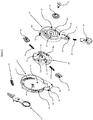
- such raising/lowering mechanism 10 provides a base member 11 intended to be integrally constrained to the outer shell 2 and comprising a guide cam 12 constituted by a curved projection which, when the base member 11 is made integral with the outer shell 2, extends transversely and preferably orthogonally with respect to the rotation axis of the protective visor 6 and which is provided with elevated or depressed portions with respect to the curved surface from which the projection rises up.
- the guide cam 12 is intended to engage with a follower projection 9 of which the side end of the protective visor 6, corresponding to the base member 11, is provided with.
- the guide cam 12, integral with the base member 11, can engage with a follower projection 9 constrained, even indirectly, to the protective visor 6 so as to integrally rotate with the visor 6 itself or, as an alternative, the follower projection 9 can be integral with the base member 11 and the guide cam 12 can be constrained so as to integrally rotate with the protective visor 6.
- such base member 11 comprises a substantially circular housing 13 having a cylindrical shape, in which a hole 14 is located for fastening the base member 11 itself to the outer shell 2, for example by a rivet 34 or threaded means, and having on its outer walls the afore said guide cam 12.
- the base member 11 further comprises a recess 15 intended to engage with an end 19 of a lever body 18 which the mechanism 10 is provided with, as will be seen later.
- the housing 13 may comprise, on the inner portions thereof, a curved rack 17 in order to allow such possible antiglare visor 6b to reach a set of stable positions by means of a follower snap-fit coupled with such rack 17 and rotationally integral with the same antiglare visor 6b or with a lever 37 to operate the latter.
- the raising/lowering mechanism 10 to raise/lower the protective visor 6 further comprises, as mentioned, an elongated lever body 18 preferably made up of a support 23, preferably in the form of a concave tubular body with a substantially circular base, and a radial extension 19 provided at its end with a pivot hole 20.
- the lever body 18 is shaped so as to be rotationally constrained to the outer shell 2 and/or to the base member 11 through the pivot hole 20, thereby allowing the support 23 to swing with respect to a first axis A-A coincident with the axis of the hole 20 and substantially orthogonal to the surface of the outer shell 2, between a position, herein named proximal, in which such support 23 is closer to the front opening 5 and a position, hereinafter named distal, in which the support 23 is further away from such front opening 5.
- such lever body 18 further comprises a projection 42, for example and preferably elastically deformable, placed at the opposite end with respect to the hole 20 and adapted to engage, also in a circumferentially sliding manner, with a respective axially retaining wall 43 which the base member 11 can be provided with, in order to allow the axial constraint between such lever body 18 and the base member 11 itself during the assembly of the mechanism 10.
- a projection 42 for example and preferably elastically deformable
- the lever body 18 is pivoted to the base member 11 by a pin 16 that is at the recess 15 of the base member 11 itself.
- the recess 15 can also define the maximum angular extent of the swing around the axis A-A of the lever body 18 and therefore of the respective support 23, for example by means of containment walls adapted to engage the afore said radial extension 19 of the lever body 18 itself.
- any other mechanical constraint allowing the lever body 18 to swing so as to allow the respective support 23 to rotate around the axis A-A, between the afore said two distal and proximal positions with respect to the front opening 5 of the helmet 1, can be alternatively implemented.
- Such lever body 18 is further subject to elastic means, preferably a helical spring 36 interposed between the base member 11, or the outer shell 2, and the lever body 18 itself, the elastic means returning the lever body 18 swinging around the axis A-A to its distal position, i.e. further away from the front opening 5 of the protecting helmet 1.
- elastic means preferably a helical spring 36 interposed between the base member 11, or the outer shell 2, and the lever body 18 itself, the elastic means returning the lever body 18 swinging around the axis A-A to its distal position, i.e. further away from the front opening 5 of the protecting helmet 1.
- the support 23 of the lever body 18 is made as a concave tubular body having a substantially circular base and comprising a cylindrical side wall having on the top thereof an outer circular base.
- On the base of this external support 23 two seats 21a, 21b shaped as circle arc are obtained and intended for the fitting of respective hooking teeth 7a, 7b, which the corresponding end of the protective visor 6 is provided with.
- fitting seats 21a, 21b are shaped so as to also act as housings having a circular development and being adapted to allow the protective visor 6 to rotate with respect to the lever body 18 around a second axis B-B, that is substantially orthogonal to these fitting seats 21a, 21b and passes through the center of the ideal circle on which such seats, or housings 21a, 21b, lie, thereby allowing the corresponding hooking teeth 7a, 7b to further slide during the relative rotation of the visor 6 with respect to the lever body 18.
- the protective visor 6, once hooked to the lever body 18 as described above, may rotate around the axis B-B defined by the fitting seats 21a, 21b, with respect to the support 23 of the lever body 18 itself and may also rotate, integrally with the lever body 18, with respect to the pivot axis A-A in which the same lever body 18 is pivoted to the base member 11.
- the support 23 of the lever body 18 can be provided with at least only one housing 21a or 21b having circular development, at least one of the hooking tooth of the visor 6 being able to rotate in a relative way within this housing although not necessarily being retained therein.
- each of the two circle-arc-shaped fitting seats 21a, 21b, or housings has a larger section, named herein "inlet ", adapted to allow the access of a respective hooking tooth 7a, 7b.
- each of these hooking teeth 7a, 7b of the protective visor 6 extends in the axial direction from the corresponding side area of the visor 6, i.e. in the direction of the rotation axes of the same visor 6, and has a substantially L-shaped profile such that it can be coupled with the respective fitting seat 21a, 21b only if there is an opening, i.e. a larger section, which allows the entrance of the end portion of the "L".
- At least one seat 21a of these two seats 21a, 21b comprises an inlet 25 intended to be partially and selectively occluded by a cursor 26 sliding in a direction transverse to the rotation axis of the protective visor 6 and being pushed by a spring 27, or other elastic means known in the art, so as to engage with such inlet 25.
- the cursor 26, that in its end engaging with the inlet 25 has a tapered portion to help the respective hooking tooth 7a to be pushed and entered therein, further comprises a shaped portion intended to be manually operated by the user to counter the force applied by the spring 27.
- hooking tooth means any portion or element of the visor 6, not necessarily projecting or L-shaped, geometrically shaped to engage with the lever body 18 so as to rotate with respect to the latter around the axis B-B and to swing with it around the axis A-A.
- such term can mean for example also a key-shaped cylindrical sleeve projecting axially from the side end of the visor 6, or an arm of a "fork-shaped” or "U-shaped” end that thereby extends orthogonal to the rotation axis B-B of the visor 6 itself.
- the support 23 of the lever body 18 also includes a central slot 22, inside which the aforementioned rotation axis B-B of the protective visor 6 passes, the support being shaped to engage with a bushing 35 retained for example by a rivet 34 fastened to the outer shell 2 and intended to ensure that the lever body 18 is suitably constrained to the outer shell 2 itself of the helmet 1 so as to rotate around the axis A-A, thanks to the elongated shape of the slot 22 itself, and at the same time so as not to be axially released from such coupling with the outer shell 2.
- the bushing 35 together with the respective rivet 34, or else any other pin or elongated element optionally threaded, axially constrained to the outer shell 2, further cause the base member 11 to be axially fastened to the same outer shell 2 thanks to the engagement of the rivet 34, or another elongated element fastened to the outer shell 2, through the above-mentioned circular hole 14 of which the substantially circular housing 13 of the base member 11 is provided with.
- the base member 11 also has lower protuberances 40a and 40b as well as an upper elastic hooking tooth 41 all of which can fit into appropriate corresponding slits provided on the side ends of the outer shell 2; thereby the base member 11 is positioned on the outer ends of the shell in a temporary and/or removable way by the elastic snap fitting of the above mentioned teeth 40a, 40b and 41. Subsequently, the same base member 11 is axially secured to the shell 2 by means of the bushing 35 with its rivet 34 or other similar axial constraining means.
- the protective visor 6 once hooked to the lever body 18 itself, can then rotate with respect to the support 23 of the lever body 18 itself around the axis B-B defined by the circle-arc-shaped fitting seats 21a, 21b, and can also rotate, or better swing, integrally with the lever body 18 around the axis A-A on which the same lever body 18 is pivoted to the base member 11, and therefore to the outer shell 2.
- the bushing or pin 35, or other elongated element, and also the slot 22 of the lever body 18 within which the bush or pin 35 engages for axially retaining the same lever body 18, must all be shaped so as to allow the rotations of the protective visor 6 with respect to both the afore said axes A-A and B-B.
- a multiple-seat profile 24 preferably shaped as a rack, intended to define a plurality of stable positions for the protective visor 6 during the raising/lowering thereof, as will be seen later.
- inside the support 23 there are two multiple-seat profiles 24 diametrically opposite with respect to the rotation axis B-B defined by the fitting seats 21a, 21b and having a circular development.
- the raising/lowering mechanism of the protecting helmet 1 described herein further comprises an intermediate disc-shaped element 28 shaped so as to couple with, or be constrained to, the support 23 of the lever body 18 so that to rotate, and in particular rotate around the afore said second axis B-B defined by the above mentioned fitting seats 21a, 21b of the support 23 itself.
- such intermediate disc-shaped element 28 is mounted to be arranged between the base member 11 and the lever body 18 so as to be able to rotate around the axis B-B and to swing, at the same time, together with the lever body 18 around the axis A-A.
- the disc-shaped element 28 is housed in the concave tubular support 23 of the lever body 18.
- the intermediate disc-shaped element 28 having a substantially circular shape, comprises a central elongated slot 30 intended to engage with the above described bushing 35 and rivet 34, and also two hollows 29a, 29b diametrically opposite with respect to the center of the disc-shaped element and intended to engage with the respective hooking teeth 7a, 7b of the corresponding side end of the protective visor 6.
- the hollows 29a, 29b, when engaged with the hooking teeth 7a, 7b of the protective visor 6, are shaped so as to allow the intermediate disc-shaped element 28 to rotate around the axis B-B, with respect to the support 23 of the lever body 18, and also to the base member 11 integrally with the visor 6, when the latter is raised or lowered. Therefore, the hollows 29a, 29b form removable constraining means for the hooking teeth 7a, 7b of the visor 6.
- the intermediate disc-shaped element 28 further comprises engaging means 31, 32, 33 integrally rotatable with the intermediate disc-shaped element 28 itself and suitable for reversibly snap fitting each time into at least one of the seats of the multiple-seat profile 24 of the support 23 of the lever body 18, during the raising or lowering of the protective visor 6.
- “snap” means herein the particular manner in which the engaging means, such as a follower element with a respective projection, are engaged and retained within depressions or recesses defining the seats of the multiple-seat profile 24 such that, thanks to the elasticity of the engaging means and/or of the multiple-seat profile 24, such engaging means are stably retained within the respective seat until a force of suitable magnitude (and direction) applied to such means causes the elastic deformation or the elastic displacement of the engaging means and/or of the multiple-seat profile 24, thereby allowing the passage of the engaging means themselves from one seat to another of this multiple-seat profile 24.
- the aforementioned engaging means are of elastic type and comprise at least one piston 32 mounted for sliding within limits in a radial guide 31 of the intermediate disc-shaped element 28 and subject to the force of a spring 33 that pushes the piston 32 toward the outside of the same disc-shaped element 28, to engage with a respective multiple-seat profile 24.
- the intermediate disc-shaped element 28 having a substantially circular shape, has two diametrically opposite radial guides 31, each housing a respective piston 32 so that the latter slides within limits, for example thanks to stops or other means ceasing the radial stroke.
- each piston 32 is pushed towards the outside of the intermediate disc-shaped element 28 by a corresponding spring 33, so as to show a tip portion that is shaped to engage within at least one, or two, adjacent seats of the multiple-seat profile 24, to which is coupled.
- the resulting rotation of the intermediate disc-shaped element 28 causes the snap movement, i.e. temporarily overcoming the force applied by the springs 33 of the pistons 32 within the respective guide 31, so as to allow those pistons 32 to be stably, although temporarily, housed in successive seats of the respective multiple-seat profiles 24 of which the support 23 of the lever body 18 is provided with.
- the protective visor 6 in this way a plurality of stable angular positions, defined by the number and distance of the seats of the profile 24, can be obtained for the protective visor 6 when the latter is raised or lowered by the user.
- the protective visor 6 comprises next to at least one of its side ends, geometrically corresponding to the raising/lowering mechanism 10 illustrated herein, at least one hooking tooth 7a, 7b which, in the embodiment of the present invention illustrated herein, is constituted by an axial projection having a L-shaped profile and at least one follower projection 9 shaped as a pin and arranged on this visor 6 in order to engage in sliding contact with the cam guide 12 of the base member 11.
- the hooking teeth 7a, 7b of the protective visor 6 are shaped to be slidingly constrained within the fitting seats 21a, 21b (or housings having circular development) of the support 23 of the lever body 18 so as to rotate with respect to the latter, and to engage with the hollows 29a, 29b of the intermediate disc-shaped element 28 so as to integrally rotate with the latter around the axis B-B, whereas the follower projection 9 is shaped to engage with the guide cam 12 and, depending on the profile of the latter, to cause the lever body 18 to possibly swing around the axis A-A, according to a law of motion precisely determined by the drive cam 12.
- the guide cam 12 is shaped so as to have an initial depressed portion for the follower projection 9, when the protective visor 6 is in its fully lowered position, then an intermediate elevated portion, and a further final depressed portion for this follower projection 9 when the visor 6 is arranged at its fully raised position.
- This geometry of the guide cam 12, together with the above described configuration of the raising/lowering mechanism 10 to raise/lower the protective visor 6, allows the lever body 18, thanks to the returning action of the spring 36, to be arranged in its distal position when the visor 6 is in its fully lowered position or in its fully raised position, and to be arranged instead in its proximal position when the visor 6 is in an intermediate position between these extremes, for example in a stable position determined by the multiple-seat profile 24.
- the above said follower projection may be formed on the intermediate disc-shaped element 28 which, as mentioned, integrally rotates with the protective visor 6, for example in a manner protruding from the circular side wall of the disc-shaped element 28 itself and, as a result, the respective guide cam 12 may be formed on the inner side wall of the circular housing 13 of the base member 11.
- At least one tooth 7a of the hooking teeth 7a, 7b is of the type orthogonally projecting from the inner wall of at least one side end of the visor 6, i.e. axially and inwardly projecting from the latter, and comprises arched shoulders 8 shaped so as to facilitate the centering of the hooking tooth 7a within the corresponding fitting seat 21a, 21b, or circular housing, of the support 23 of the lever body 18.
- these arched shoulders 8 project from the inner face of the side end of the protective visor 6 only along a limited part of the entire height of the hooking tooth 7a.
- the protecting helmet 1 of the present invention may also comprise an antiglare visor 6b (i.e. to protect against light rays) manually operable by the user of the helmet 1 itself thanks, for example, to a lever 37 rotatably mounted on the base member 11 and kinematically linked to such antiglare visor 6b so as to be able to lower or raise it with respect to the eye of the same user.
- an antiglare visor 6b i.e. to protect against light rays
- a lever 37 rotatably mounted on the base member 11 and kinematically linked to such antiglare visor 6b so as to be able to lower or raise it with respect to the eye of the same user.
- the protecting helmet 1 comprises two raising/lowering mechanisms 10 to raise/lower the visor 6, the two mechanisms, each located at one of the two sides of the front opening 5 of the helmet 1, having double rotation axis (A-A and B-B) and being, for example, substantially identical to each other.
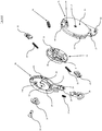
- the protecting helmet 1 provided, on each side of the front opening 5, with a raising/lowering mechanism 10 to raise/lower the visor 6 illustrated herein with reference also to Figures 5a and 5b , works as follows.
- the visor 6 has to be mounted on the raising/lowering mechanism 10.
- the visor 6 has to be first arranged in its fully raised position so as to position, per each side, the hooking teeth 7a, 7b at the inlets of the fitting seats, 21a, 21b or housing having a circular development of the support 23 of the lever body 18.
- the aforesaid inlets of the fitting seats 21a, 21b are shaped so that they geometrically match the hooking teeth 7a, 7b when the visor 6 is in the fully raised position, and that one of the inlets 25 of one of the fitting seats 21a is at least partially occluded by a cursor 26 provided with a tapered end at such inlet 25 and elastically pushed, for example and preferably by the spring 27, to engage with such inlet 25.
- the hooking teeth 7a, 7b, inserted in the seats 21a, 21b reach the hollows 29a, 29b of the intermediate disc-shaped element 28 and engage therein, thus causing the protective visor 6 and this intermediate disc-shaped element 28 to be constrained to each other so as to integrally rotate around a rotation axis B-B defined, inter alia, by the above-mentioned fitting seats 21a, 21b.
- the raising/lowering mechanism 10 is constrained to the raising/lowering mechanism 10 so as to be able to rotate integrally with the intermediate disc-shaped element 28 and with respect to the lever body 18 around an axis B-B, and at the same time to be able to swing, together with the support 23 of the lever body 18, with respect to the base member 11 around a different axis A-A, in this case the axis of the pin 16 around which the lever body 18 rotates, this swing being controlled by the engagement of the follower projection with the guide cam 12 of the base member 11 during the raising/lowering of the visor 6 operated by the user.
- this visor 6 is in its upper and completely raised position with respect to the front opening 5 of the outer shell 2, thanks to the fact that the engagement of the follower projection 9 with the guide cam 12, having a depressed portion at this raised position of the visor 6, together with the return spring 36 acting on the lever body 18, cause the support 23 of the same lever body 18 to be arranged in its position distal from the front opening 5 of the protecting helmet 1, corresponding to a position of close proximity of the visor 6 with respect to the outer shell 2.
- the lowering rotation imparted by the user to the protective visor 6 itself causes, thanks to the shape of the guide cam 12 - having as mentioned an intermediate elevated portion - and by overcoming the force of the return spring 36, the support 23 of the lever body 18 to swing around the axis A-A toward its position proximal to the front opening 5 of the helmet 1 and, at the same time, the simultaneous rotation of the visor 6 itself around the second axis B-B with respect to the body lever 18, integrally with the intermediate disc-shaped element 28.
- the visor 6 is raised with respect to the outer shell 2 towards its position proximal to the front opening of the helmet 5 and, at the same time, rotates together with the intermediate disc-shaped element 28 with respect to the same support 23 of the lever body 18.
- the shape of the guide cam 12, which has a further depressed portion causes a further swing of the support 23 of the lever body 18 around the axis A-A towards its position distal from the front opening 5, thanks to its engagement with the follower projection 9 of the same visor 6 and also thanks to the return spring 36.
- This causes, at the complete lowering of the protective visor 6, a new approach of the latter with respect to the outer shell 2 of the helmet 1.
- mechanism 10 can be easily assembled by substantially snapping it into place.
- pistons 32 are housed and retained in respective sliding guides 31 present in the intermediate disc-shaped element 28.
- This intermediate assembly is inserted in the seat 23 of the lever body 18 by partially compressing the opposite pistons 32, and then by inserting also the cursor 26 with the respective spring 27 into a suitable seat of the same component 28.
- the previous group of components is assembled on the base member 11 by taking care of passing the end 19 of the lever body 18 through the opening 15 in the base member 11 and by hooking the pin 16 into the hole 20; subsequently, by pressing the opposite end of the lever body 18, i.e. at the projection 42 thereof, against the base member, the elastic engagement is obtained between the projection 42 itself and the retaining wall 43 of the housing 13 of the base member 11.
- the projection 42 of the lever body 18 and/or the respective retaining wall 43 of the base member 11 are elastically deformable in order to allow such elastic coupling. It should be noted that, at this step, it is necessary to take care that the cursor 26 remains on the opposite surface of the base member 11.
- the mechanism 10 is fully assembled and ready to be mounted on the side parts of the shell by means of a temporary positioning obtained through elastic hooks 40a, 40b and 41 and the final fastening by the bushing 35 and the rivet 34.
Landscapes
- Helmets And Other Head Coverings (AREA)
Claims (15)
- Schutzhelm (1) der Bauart, die mit wenigstens einer inneren Schale (3) zur Stoßdämpfung und wenigstens einer äußeren starren Schale (2) versehen ist, die eine vordere Öffnung (5) für das Gesicht eines Benutzers definiert, sowie mit einem Schutzvisier (6), das wenigstens zwischen einer abgesenkten Stellung drehbar ist, die zumindest teilweise in die vordere Öffnung (5) eingreift, und einer angehobenen Stellung, die von der vorderen Öffnung (5) entkuppelt ist, und einem Hebe-/Senkmechanismus (10) zum Anheben/Absenken des Schutzvisiers, wobei der Hebe-/Senkmechanismus umfasst:• mindestens ein Basiselement (11), das verblockt ist oder einstückig ausgebildet ist mit einem Teil der äußeren Schale (2) oder mit dieser zusammenfällt, und in einer Seitenposition bezüglich der vorderen Öffnung angeordnet ist;• ein Hebelelement (18), das an der äußeren Schale (2) oder dem Basiselement (11) angebracht ist, um sich um eine erste Achse (A-A) zu drehen und mit einer Halterung (23) versehen ist, die in Bezug auf die erste Achse (A-A) zwischen einer proximalen Stellung und einer distalen Stellung in Bezug auf die vordere Öffnung (5) schwenkt, wobei die Halterung (23) weiterhin Einhakmittel (21a, 21b, 26, 27) umfasst, um mit einem entsprechenden Seitenbereich des Schutzvisiers (6) zu verhaken;• elastische Rückstellmittel (36), die an der äußeren Schale (2) oder dem Basiselement (11) befestigt sind und auf das Hebelelement (18) einwirken, um es in seine distale Stellung zu drücken;• einen oder mehrere Einhakzähne (7a, 7b), die einstückig mit dem Seitenbereich des Schutzvisiers ausgebildet sind und für den Eingriff mit den Einhakmitteln (21a, 21b, 26, 27) des Hebelelements (18) geformt sind;• mindestens eine Führungsnocke (12) und ein jeweiliger Mitnehmervorsprung (9), der mit der Führungsnocke (12) in Eingriff steht, wobei die mindestens eine Führungsnocke (12) einstückig mit dem mindestens einen Basiselement (11) ist und der jeweilige Mitnehmervorsprung (9) derart befestigt ist, dass er sich integral mit dem ersten Seitenbereich des Schutzvisiers (6), oder umgekehrt, dreht;dadurch gekennzeichnet, dass die Halterung (23) des Hebelelements (18) mindestens ein Mehrfachsitzprofil (24) aufweist und dass der Anhebe-/Absenkmechanismus (10) ferner ein scheibenförmiges Zwischenelement (28) umfasst, das mit der Halterung (23) des Hebelelements (18) so gekoppelt ist, um sich in Bezug auf die Halterung (23) um eine zweite Achse (B-B) zu drehen und auch in Bezug auf die erste Achse (A-A) einstückig mit der Halterung (23) des Hebelelements (18) zu schwenken, und weiterhin Befestigungsmittel (29a, 29b) für die lösbare Befestigung an mindestens einem der Einhakzähne (7a; 7b) des Schutzvisiers (6) angeordnet sind, um mindestens die kreisförmige Bewegung des Schutzvisiers (6) während des Anhebens oder Absenkens desselben auf das scheibenförmige Zwischenelement (28) zu übertragen, sowie Eingriffsmittel (31, 32, 33) angeordnet sind, die zumindest einstückig mit dem scheibenförmigen Zwischenelement (28) drehbar sind, für die bewegliche Schnappverbindung mit dem mindestens einen Mehrfachsitzprofil (24).
- Schutzhelm (1) gemäß Anspruch 1, dadurch gekennzeichnet, dass der Hebe-/Senkmechanismus (10) des Schutzvisiers (6) einen Stift (34) und/oder eine Befestigungsbuchse (35) umfasst zum axialen Halten des Hebelelements (18) und des scheibenförmigen Zwischenelements (28) in Verbindung mit dem Basiselement (11), wobei das Hebelelement (18) und das scheibenförmige Zwischenelement (11) längliche Schlitze (22, 30) zum Durchtritt des Stifts oder der Befestigungsbuchse aufweist, um das Schwenken des Hebelelements (18) und des scheibenförmigen Zwischenelements (28) zu ermöglichen.
- Schutzhelm (1) gemäß irgendeinem der vorhergehenden Ansprüche, wobei die Einhakmittel (21a, 21b, 26, 27), mit denen das Hebelelement (18) versehen ist, mindestens eine Aufnahme (21a; 21b) mit einer kreisförmigen Gestaltung umfassen zum Gleiten des mindestens einen der Einhakzähne (7a; 7b) des Schutzvisiers (6) während der Relativdrehung des Schutzvisiers in Bezug auf das Hebelelement.
- Schutzhelm (1) gemäß irgendeinem der vorhergehenden Ansprüche, wobei die Einhakmittel (21a, 21b, 26, 27) zum Einhaken des Hebelelements (18) an einem jeweiligen Seitenbereich des Schutzvisiers (6) von der reversiblen Bauart sind und mindestens einen Passsitz (21a) für mindestens einen Einhakzahn (7a) des Schutzvisiers (6) umfassen, wobei der mindestens eine Passsitz mit einem Einlass (25) versehen ist, so dass ein manuell betätigter elastischer Zeiger (26, 27) teilweise und selektiv verdeckt werden kann.
- Schutzhelm (1) gemäß Anspruch 3 und 4, wobei die Aufnahmen (21a, 21b), die eine kreisförmige Gestaltung aufweisen, mit dem mindestens einen Passsitz für mindestens einen Einhakzahn zusammenfallen.
- Schutzhelm (1) gemäß irgendeinem der vorhergehenden Ansprüche, dadurch gekennzeichnet, dass mindestens einer (7a) der Einhakzähne (7a, 7b) des Schutzvisiers (6) axial von dem Seitenende des Schutzvisiers (6) nach innen vorsteht und gewölbte Randanschläge (8) für die Zentrierung in einem jeweiligen Passsitz aufweist und/oder in eine jeweilige Aufnahme hineinragt, die eine kreisförmige Gestaltung aufweist, mit der die Halterung (23) des Hebelelements (18) versehen ist.
- Schutzhelm (1) gemäß irgendeinem der vorhergehenden Ansprüche, wobei das Hebelelement (18) durch einen Stift (34) an der äußeren Schale (2) des Helms befestigt ist.
- Schutzhelm (1) gemäß irgendeinem der vorhergehenden Ansprüche, dadurch gekennzeichnet, dass die Eingriffsmittel (31, 32, 33) für die Schnappbefestigung, mit denen das scheibenförmige Zwischenelement (28) versehen ist, mindestens einen Kolben (32) umfasst, der in Grenzen in einer jeweiligen radialen Führung (31) gleitet, und eine Druckfeder (33), die auf den mindestens einen Kolben (32) wirkt.
- Schutzhelm (1) gemäß irgendeinem der vorhergehenden Ansprüche, wobei die Halterung (23) des Hebelelements (18) eine röhrenförmige Gestalt mit einer im Wesentlichen kreisförmigen Basis aufweist und das scheibenförmige Zwischenelement (28) zumindest teilweise in der röhrenförmigen Halterung (23) untergebracht ist.
- Schutzhelm (1) gemäß irgendeinem der vorhergehenden Ansprüche, dadurch gekennzeichnet, dass das Basiselement (11) getrennt von der äußeren Schale (2) hergestellt ist und ein im Wesentlichen kreisförmiges Gehäuse (13) für zumindest einen Teil des scheibenförmigen Zwischenelements (28) umfasst, wobei das Gehäuse (13) die Führungsnocke (12) an der Außenseite aufweist.
- Schutzhelm (1) gemäß irgendeinem der vorhergehenden Ansprüche, wobei die elastischen Rückstellmittel eine Schraubenfeder (36) umfassen.
- Schutzhelm (1) gemäß irgendeinem der vorhergehenden Ansprüche, wobei das mindestens eine Mehrfachsitzprofil eine Zahnstange (17) ist.
- Schutzhelm (1) gemäß irgendeinem der vorhergehenden Ansprüche, gekennzeichnet durch das Vorhandensein eines zweiten Visiers (6b) vom Blendschutztyp.
- Schutzhelm (1) gemäß Anspruch 13, gekennzeichnet durch das Vorhandensein eines manuell betätigten Hebels (37) für das zweite Visier.
- Schutzhelm (1) gemäß irgendeinem der vorhergehenden Ansprüche, dadurch gekennzeichnet, dass er zwei Hebe-/Senkmechanismen (10) zum Heben/Senken des Schutzvisiers (6) gemäß irgendeinem der Ansprüche 1 bis 14 aufweist, die sich an beiden Seiten der vorderen Öffnung (5) des Helms (1) befinden.
Applications Claiming Priority (1)
| Application Number | Priority Date | Filing Date | Title |
|---|---|---|---|
| ITUB2015A003158A ITUB20153158A1 (it) | 2015-08-18 | 2015-08-18 | Casco di protezione con meccanismo di sollevamento/abbassamento della visiera |
Publications (2)
| Publication Number | Publication Date |
|---|---|
| EP3132702A1 EP3132702A1 (de) | 2017-02-22 |
| EP3132702B1 true EP3132702B1 (de) | 2018-01-31 |
Family
ID=54705734
Family Applications (1)
| Application Number | Title | Priority Date | Filing Date |
|---|---|---|---|
| EP16184074.9A Active EP3132702B1 (de) | 2015-08-18 | 2016-08-12 | Schutzhelm mit einem mechanismus zum öffnen und schliessen des visiers |
Country Status (6)
| Country | Link |
|---|---|
| US (1) | US10568380B2 (de) |
| EP (1) | EP3132702B1 (de) |
| JP (1) | JP6927677B2 (de) |
| AU (1) | AU2016213804B2 (de) |
| ES (1) | ES2666228T3 (de) |
| IT (1) | ITUB20153158A1 (de) |
Cited By (1)
| Publication number | Priority date | Publication date | Assignee | Title |
|---|---|---|---|---|
| TWI684418B (zh) * | 2019-03-27 | 2020-02-11 | 隆輝安全帽有限公司 | 複合式頭盔護罩固定裝置 |
Families Citing this family (25)
| Publication number | Priority date | Publication date | Assignee | Title |
|---|---|---|---|---|
| US10154704B1 (en) * | 2015-04-17 | 2018-12-18 | Desmark Industries, Inc. | Helmet slide assembly |
| IT201600083163A1 (it) * | 2016-08-05 | 2018-02-05 | Nolangroup Spa | Casco con elemento di imbottitura rimovibile |
| CN106723602B (zh) * | 2017-02-24 | 2022-05-27 | 上海和汇安全用品有限公司 | 镜片用锁止机构、镜片组件及头盔 |
| JP1616683S (de) * | 2018-05-07 | 2018-10-29 | ||
| JP1630425S (de) | 2018-06-05 | 2019-05-07 | ||
| IT201800007484A1 (it) | 2018-07-25 | 2020-01-25 | Nolangroup Spa | Casco di protezione con imbottitura di conforto regolabile |
| IT201800007541A1 (it) * | 2018-07-26 | 2020-01-26 | Nolangroup Spa | Casco di protezione con meccanismo di sollevamento/abbassamento della visiera |
| IT201800007545A1 (it) | 2018-07-26 | 2020-01-26 | Nolangroup Spa | Casco di protezione con meccanismo di sollevamento/abbassamento della visiera |
| US10973274B2 (en) | 2018-07-31 | 2021-04-13 | Kimpex Inc. | Helmet, mounting system for a helmet and method of using same |
| US10786032B2 (en) * | 2019-01-18 | 2020-09-29 | Cookie Composites Group Pty Ltd. | Skydiving helmet and visor mounting system |
| US11213089B2 (en) * | 2019-06-04 | 2022-01-04 | Msa Technology, Llc | Protective helmet with face protection shield and linkage mechanism |
| JP1682279S (de) | 2020-07-30 | 2021-03-29 | ||
| JP1682280S (de) * | 2020-07-30 | 2021-03-29 | ||
| US12220016B1 (en) * | 2020-09-16 | 2025-02-11 | Riddell, Inc. | Protective sports helmet with advanced visor system, lower chin bar assembly and energy attenuation system |
| US11583026B2 (en) | 2021-02-09 | 2023-02-21 | LIFT Airborne Technologies LLC | Automatic visor locking system |
| CA3189539A1 (en) | 2022-02-17 | 2023-08-17 | Kimpex Inc. | Visor assembly with unique plate |
| USD1064417S1 (en) * | 2022-05-24 | 2025-02-25 | HJC Corporation | Helmet |
| USD1063226S1 (en) * | 2022-05-25 | 2025-02-18 | HJC Corporation | Helmet |
| USD1088357S1 (en) * | 2022-06-07 | 2025-08-12 | Locatelli S.p.A | Helmet |
| JP1750636S (de) * | 2022-08-24 | 2023-08-10 | ||
| JP1750635S (de) * | 2022-08-24 | 2023-08-10 | ||
| JP1750637S (de) * | 2022-08-24 | 2023-08-10 | ||
| USD1077364S1 (en) * | 2022-12-06 | 2025-05-27 | Locatelli S.P.A. | Helmet |
| CN117179413B (zh) * | 2023-09-21 | 2025-07-04 | 江门市鹏程头盔有限公司 | 一种头盔 |
| USD1073193S1 (en) * | 2024-04-18 | 2025-04-29 | Shark | Motorcycle helmet |
Family Cites Families (15)
| Publication number | Priority date | Publication date | Assignee | Title |
|---|---|---|---|---|
| GB2135866B (en) * | 1983-03-04 | 1986-10-22 | Helmets Ltd | Helmet with visor mechanism |
| DE3607483C2 (de) * | 1986-03-07 | 1995-07-27 | Piech Corina | Schutzhelm |
| EP0797935B1 (de) | 1996-03-18 | 1999-09-22 | E.D.C. Sa | Integralhelm für Motorradfahrer oder dergleichen mit Vorrichtung zum Öffnen/Schliessen des Kinnbügels |
| US6264392B1 (en) * | 1999-08-25 | 2001-07-24 | Mine Safety Appliances Company | Pivot joint for faceshield assembly |
| EP1366683A1 (de) * | 2002-05-27 | 2003-12-03 | OPTICOS S.r.l. | Vorrichtung zur Befestigung des Visiers eines Helmes für Motorradfahrer |
| KR200344909Y1 (ko) | 2003-12-26 | 2004-03-18 | (주)기도산업 | 시일드의 회전중심 가변형 헬멧 |
| US7814579B2 (en) * | 2004-09-27 | 2010-10-19 | Kbc America, Inc. | Modular helmet |
| ITMI20051839A1 (it) * | 2005-09-30 | 2007-04-01 | Opticos Srl | Congegno di controllo della posizione di una visiera per caschi di protezione |
| JP5016893B2 (ja) * | 2006-05-15 | 2012-09-05 | 株式会社Shoei | ヘルメットのシールド取付け機構 |
| US8069499B2 (en) * | 2006-05-15 | 2011-12-06 | Shoei Co., Ltd. | Helmet shield attaching mechanism, and helmet attached with the same |
| GB0806907D0 (en) * | 2008-04-16 | 2008-05-21 | Milan Guy | Packaging locking and indication system |
| KR101150796B1 (ko) * | 2009-07-29 | 2012-06-13 | 주식회사 홍진에이치제이씨 | 헬멧 |
| US8635715B2 (en) * | 2010-12-09 | 2014-01-28 | Cookie Composites | Helmet and visor locking mechanism |
| JP6148538B2 (ja) * | 2013-06-03 | 2017-06-14 | 株式会社Shoei | ヘルメットのシールド取付け機構 |
| US10264842B2 (en) * | 2013-09-16 | 2019-04-23 | Otos Wing Co., Ltd. | Coupling structure of replaceable visor hinge for headband |
-
2015
- 2015-08-18 IT ITUB2015A003158A patent/ITUB20153158A1/it unknown
-
2016
- 2016-08-10 US US15/233,127 patent/US10568380B2/en active Active
- 2016-08-11 AU AU2016213804A patent/AU2016213804B2/en active Active
- 2016-08-12 EP EP16184074.9A patent/EP3132702B1/de active Active
- 2016-08-12 ES ES16184074.9T patent/ES2666228T3/es active Active
- 2016-08-15 JP JP2016159060A patent/JP6927677B2/ja active Active
Non-Patent Citations (1)
| Title |
|---|
| None * |
Cited By (1)
| Publication number | Priority date | Publication date | Assignee | Title |
|---|---|---|---|---|
| TWI684418B (zh) * | 2019-03-27 | 2020-02-11 | 隆輝安全帽有限公司 | 複合式頭盔護罩固定裝置 |
Also Published As
| Publication number | Publication date |
|---|---|
| US10568380B2 (en) | 2020-02-25 |
| ES2666228T3 (es) | 2018-05-03 |
| JP2017078247A (ja) | 2017-04-27 |
| US20170215508A1 (en) | 2017-08-03 |
| EP3132702A1 (de) | 2017-02-22 |
| AU2016213804A1 (en) | 2017-03-09 |
| JP6927677B2 (ja) | 2021-09-01 |
| ITUB20153158A1 (it) | 2017-02-18 |
| AU2016213804B2 (en) | 2020-11-12 |
Similar Documents
| Publication | Publication Date | Title |
|---|---|---|
| AU2016213804B2 (en) | Protecting helmet with raising/lowering mechanism of the visor | |
| US8250669B2 (en) | Safety helmet with supplemental inner visor | |
| KR101858483B1 (ko) | 헬멧 | |
| US9167861B2 (en) | Safety helmet with anti-dazzle visor | |
| JP5050259B2 (ja) | 遮蔽要素を備える安全ヘルメット | |
| ES2350382T3 (es) | Conjunto de guantera para un salpicadero de un vehículo a motor. | |
| JP5084213B2 (ja) | 保護ヘルメット用バイザーの位置を制御するための装置 | |
| US20200229529A1 (en) | Skydiving Helmet and Visor Mounting System | |
| EP0502272A1 (de) | Helm mit Augenschirm | |
| JP4428754B2 (ja) | ヘルメット | |
| US20030088907A1 (en) | Device for unhooking the visor from the cap of a crash-helmet, in particular for motorcycling | |
| EP2628402B1 (de) | Helm mit einer Verstellvorrichtung zum Bewegen eines ersten Elements des Helms in bezug auf ein zweit | |
| CN110771981A (zh) | 带遮护件的升降机构的保护头盔 | |
| EP2063727B1 (de) | Sturzhelm, besonders für die verwendung im zusammenhang mit kraftfahrzeugen und beim sport im allgemeinen | |
| US8495763B2 (en) | Safety helmet with raisable chin-guard | |
| JP2020534110A (ja) | 注射器の注射針挿入機構 | |
| CN117355236A (zh) | 用于头盔面罩的枢转紧固机构 | |
| US8151375B2 (en) | Mechanism for assembly and disassembly of helmet visors | |
| EP2818066B1 (de) | Motorradhelm | |
| CN120166926A (zh) | 头盔护罩附接机构和包括这种护罩附接机构的保护头盔 |
Legal Events
| Date | Code | Title | Description |
|---|---|---|---|
| PUAI | Public reference made under article 153(3) epc to a published international application that has entered the european phase |
Free format text: ORIGINAL CODE: 0009012 |
|
| AK | Designated contracting states |
Kind code of ref document: A1 Designated state(s): AL AT BE BG CH CY CZ DE DK EE ES FI FR GB GR HR HU IE IS IT LI LT LU LV MC MK MT NL NO PL PT RO RS SE SI SK SM TR |
|
| AX | Request for extension of the european patent |
Extension state: BA ME |
|
| GRAJ | Information related to disapproval of communication of intention to grant by the applicant or resumption of examination proceedings by the epo deleted |
Free format text: ORIGINAL CODE: EPIDOSDIGR1 |
|
| GRAP | Despatch of communication of intention to grant a patent |
Free format text: ORIGINAL CODE: EPIDOSNIGR1 |
|
| 17P | Request for examination filed |
Effective date: 20170816 |
|
| RBV | Designated contracting states (corrected) |
Designated state(s): AL AT BE BG CH CY CZ DE DK EE ES FI FR GB GR HR HU IE IS IT LI LT LU LV MC MK MT NL NO PL PT RO RS SE SI SK SM TR |
|
| RIC1 | Information provided on ipc code assigned before grant |
Ipc: A42B 3/22 20060101AFI20170831BHEP |
|
| INTG | Intention to grant announced |
Effective date: 20170915 |
|
| GRAS | Grant fee paid |
Free format text: ORIGINAL CODE: EPIDOSNIGR3 |
|
| GRAA | (expected) grant |
Free format text: ORIGINAL CODE: 0009210 |
|
| AK | Designated contracting states |
Kind code of ref document: B1 Designated state(s): AL AT BE BG CH CY CZ DE DK EE ES FI FR GB GR HR HU IE IS IT LI LT LU LV MC MK MT NL NO PL PT RO RS SE SI SK SM TR |
|
| REG | Reference to a national code |
Ref country code: GB Ref legal event code: FG4D Ref country code: CH Ref legal event code: EP |
|
| REG | Reference to a national code |
Ref country code: AT Ref legal event code: REF Ref document number: 966537 Country of ref document: AT Kind code of ref document: T Effective date: 20180215 |
|
| REG | Reference to a national code |
Ref country code: IE Ref legal event code: FG4D |
|
| REG | Reference to a national code |
Ref country code: DE Ref legal event code: R096 Ref document number: 602016001546 Country of ref document: DE |
|
| REG | Reference to a national code |
Ref country code: ES Ref legal event code: FG2A Ref document number: 2666228 Country of ref document: ES Kind code of ref document: T3 Effective date: 20180503 |
|
| REG | Reference to a national code |
Ref country code: NL Ref legal event code: MP Effective date: 20180131 |
|
| REG | Reference to a national code |
Ref country code: LT Ref legal event code: MG4D |
|
| REG | Reference to a national code |
Ref country code: AT Ref legal event code: MK05 Ref document number: 966537 Country of ref document: AT Kind code of ref document: T Effective date: 20180131 |
|
| PG25 | Lapsed in a contracting state [announced via postgrant information from national office to epo] |
Ref country code: NL Free format text: LAPSE BECAUSE OF FAILURE TO SUBMIT A TRANSLATION OF THE DESCRIPTION OR TO PAY THE FEE WITHIN THE PRESCRIBED TIME-LIMIT Effective date: 20180131 Ref country code: FI Free format text: LAPSE BECAUSE OF FAILURE TO SUBMIT A TRANSLATION OF THE DESCRIPTION OR TO PAY THE FEE WITHIN THE PRESCRIBED TIME-LIMIT Effective date: 20180131 Ref country code: LT Free format text: LAPSE BECAUSE OF FAILURE TO SUBMIT A TRANSLATION OF THE DESCRIPTION OR TO PAY THE FEE WITHIN THE PRESCRIBED TIME-LIMIT Effective date: 20180131 Ref country code: HR Free format text: LAPSE BECAUSE OF FAILURE TO SUBMIT A TRANSLATION OF THE DESCRIPTION OR TO PAY THE FEE WITHIN THE PRESCRIBED TIME-LIMIT Effective date: 20180131 Ref country code: NO Free format text: LAPSE BECAUSE OF FAILURE TO SUBMIT A TRANSLATION OF THE DESCRIPTION OR TO PAY THE FEE WITHIN THE PRESCRIBED TIME-LIMIT Effective date: 20180430 |
|
| REG | Reference to a national code |
Ref country code: FR Ref legal event code: PLFP Year of fee payment: 3 |
|
| PG25 | Lapsed in a contracting state [announced via postgrant information from national office to epo] |
Ref country code: SE Free format text: LAPSE BECAUSE OF FAILURE TO SUBMIT A TRANSLATION OF THE DESCRIPTION OR TO PAY THE FEE WITHIN THE PRESCRIBED TIME-LIMIT Effective date: 20180131 Ref country code: LV Free format text: LAPSE BECAUSE OF FAILURE TO SUBMIT A TRANSLATION OF THE DESCRIPTION OR TO PAY THE FEE WITHIN THE PRESCRIBED TIME-LIMIT Effective date: 20180131 Ref country code: BG Free format text: LAPSE BECAUSE OF FAILURE TO SUBMIT A TRANSLATION OF THE DESCRIPTION OR TO PAY THE FEE WITHIN THE PRESCRIBED TIME-LIMIT Effective date: 20180430 Ref country code: RS Free format text: LAPSE BECAUSE OF FAILURE TO SUBMIT A TRANSLATION OF THE DESCRIPTION OR TO PAY THE FEE WITHIN THE PRESCRIBED TIME-LIMIT Effective date: 20180131 Ref country code: AT Free format text: LAPSE BECAUSE OF FAILURE TO SUBMIT A TRANSLATION OF THE DESCRIPTION OR TO PAY THE FEE WITHIN THE PRESCRIBED TIME-LIMIT Effective date: 20180131 Ref country code: IS Free format text: LAPSE BECAUSE OF FAILURE TO SUBMIT A TRANSLATION OF THE DESCRIPTION OR TO PAY THE FEE WITHIN THE PRESCRIBED TIME-LIMIT Effective date: 20180531 Ref country code: GR Free format text: LAPSE BECAUSE OF FAILURE TO SUBMIT A TRANSLATION OF THE DESCRIPTION OR TO PAY THE FEE WITHIN THE PRESCRIBED TIME-LIMIT Effective date: 20180501 Ref country code: PL Free format text: LAPSE BECAUSE OF FAILURE TO SUBMIT A TRANSLATION OF THE DESCRIPTION OR TO PAY THE FEE WITHIN THE PRESCRIBED TIME-LIMIT Effective date: 20180131 |
|
| PG25 | Lapsed in a contracting state [announced via postgrant information from national office to epo] |
Ref country code: RO Free format text: LAPSE BECAUSE OF FAILURE TO SUBMIT A TRANSLATION OF THE DESCRIPTION OR TO PAY THE FEE WITHIN THE PRESCRIBED TIME-LIMIT Effective date: 20180131 Ref country code: EE Free format text: LAPSE BECAUSE OF FAILURE TO SUBMIT A TRANSLATION OF THE DESCRIPTION OR TO PAY THE FEE WITHIN THE PRESCRIBED TIME-LIMIT Effective date: 20180131 Ref country code: AL Free format text: LAPSE BECAUSE OF FAILURE TO SUBMIT A TRANSLATION OF THE DESCRIPTION OR TO PAY THE FEE WITHIN THE PRESCRIBED TIME-LIMIT Effective date: 20180131 |
|
| REG | Reference to a national code |
Ref country code: DE Ref legal event code: R097 Ref document number: 602016001546 Country of ref document: DE |
|
| PG25 | Lapsed in a contracting state [announced via postgrant information from national office to epo] |
Ref country code: SM Free format text: LAPSE BECAUSE OF FAILURE TO SUBMIT A TRANSLATION OF THE DESCRIPTION OR TO PAY THE FEE WITHIN THE PRESCRIBED TIME-LIMIT Effective date: 20180131 Ref country code: SK Free format text: LAPSE BECAUSE OF FAILURE TO SUBMIT A TRANSLATION OF THE DESCRIPTION OR TO PAY THE FEE WITHIN THE PRESCRIBED TIME-LIMIT Effective date: 20180131 Ref country code: DK Free format text: LAPSE BECAUSE OF FAILURE TO SUBMIT A TRANSLATION OF THE DESCRIPTION OR TO PAY THE FEE WITHIN THE PRESCRIBED TIME-LIMIT Effective date: 20180131 Ref country code: CZ Free format text: LAPSE BECAUSE OF FAILURE TO SUBMIT A TRANSLATION OF THE DESCRIPTION OR TO PAY THE FEE WITHIN THE PRESCRIBED TIME-LIMIT Effective date: 20180131 |
|
| PLBE | No opposition filed within time limit |
Free format text: ORIGINAL CODE: 0009261 |
|
| STAA | Information on the status of an ep patent application or granted ep patent |
Free format text: STATUS: NO OPPOSITION FILED WITHIN TIME LIMIT |
|
| 26N | No opposition filed |
Effective date: 20181102 |
|
| PG25 | Lapsed in a contracting state [announced via postgrant information from national office to epo] |
Ref country code: SI Free format text: LAPSE BECAUSE OF FAILURE TO SUBMIT A TRANSLATION OF THE DESCRIPTION OR TO PAY THE FEE WITHIN THE PRESCRIBED TIME-LIMIT Effective date: 20180131 |
|
| PG25 | Lapsed in a contracting state [announced via postgrant information from national office to epo] |
Ref country code: MC Free format text: LAPSE BECAUSE OF FAILURE TO SUBMIT A TRANSLATION OF THE DESCRIPTION OR TO PAY THE FEE WITHIN THE PRESCRIBED TIME-LIMIT Effective date: 20180131 |
|
| PG25 | Lapsed in a contracting state [announced via postgrant information from national office to epo] |
Ref country code: LU Free format text: LAPSE BECAUSE OF NON-PAYMENT OF DUE FEES Effective date: 20180812 |
|
| REG | Reference to a national code |
Ref country code: BE Ref legal event code: MM Effective date: 20180831 |
|
| REG | Reference to a national code |
Ref country code: IE Ref legal event code: MM4A |
|
| PG25 | Lapsed in a contracting state [announced via postgrant information from national office to epo] |
Ref country code: IE Free format text: LAPSE BECAUSE OF NON-PAYMENT OF DUE FEES Effective date: 20180812 |
|
| PG25 | Lapsed in a contracting state [announced via postgrant information from national office to epo] |
Ref country code: BE Free format text: LAPSE BECAUSE OF NON-PAYMENT OF DUE FEES Effective date: 20180831 |
|
| PG25 | Lapsed in a contracting state [announced via postgrant information from national office to epo] |
Ref country code: MT Free format text: LAPSE BECAUSE OF NON-PAYMENT OF DUE FEES Effective date: 20180812 |
|
| PG25 | Lapsed in a contracting state [announced via postgrant information from national office to epo] |
Ref country code: TR Free format text: LAPSE BECAUSE OF FAILURE TO SUBMIT A TRANSLATION OF THE DESCRIPTION OR TO PAY THE FEE WITHIN THE PRESCRIBED TIME-LIMIT Effective date: 20180131 |
|
| PG25 | Lapsed in a contracting state [announced via postgrant information from national office to epo] |
Ref country code: LI Free format text: LAPSE BECAUSE OF NON-PAYMENT OF DUE FEES Effective date: 20190831 Ref country code: CH Free format text: LAPSE BECAUSE OF NON-PAYMENT OF DUE FEES Effective date: 20190831 Ref country code: PT Free format text: LAPSE BECAUSE OF FAILURE TO SUBMIT A TRANSLATION OF THE DESCRIPTION OR TO PAY THE FEE WITHIN THE PRESCRIBED TIME-LIMIT Effective date: 20180131 |
|
| PG25 | Lapsed in a contracting state [announced via postgrant information from national office to epo] |
Ref country code: MK Free format text: LAPSE BECAUSE OF NON-PAYMENT OF DUE FEES Effective date: 20180131 Ref country code: HU Free format text: LAPSE BECAUSE OF FAILURE TO SUBMIT A TRANSLATION OF THE DESCRIPTION OR TO PAY THE FEE WITHIN THE PRESCRIBED TIME-LIMIT; INVALID AB INITIO Effective date: 20160812 Ref country code: CY Free format text: LAPSE BECAUSE OF FAILURE TO SUBMIT A TRANSLATION OF THE DESCRIPTION OR TO PAY THE FEE WITHIN THE PRESCRIBED TIME-LIMIT Effective date: 20180131 |
|
| P01 | Opt-out of the competence of the unified patent court (upc) registered |
Effective date: 20230527 |
|
| PGFP | Annual fee paid to national office [announced via postgrant information from national office to epo] |
Ref country code: ES Payment date: 20250902 Year of fee payment: 10 |
|
| PGFP | Annual fee paid to national office [announced via postgrant information from national office to epo] |
Ref country code: DE Payment date: 20250805 Year of fee payment: 10 |
|
| PGFP | Annual fee paid to national office [announced via postgrant information from national office to epo] |
Ref country code: IT Payment date: 20250731 Year of fee payment: 10 |
|
| PGFP | Annual fee paid to national office [announced via postgrant information from national office to epo] |
Ref country code: GB Payment date: 20250725 Year of fee payment: 10 |
|
| PGFP | Annual fee paid to national office [announced via postgrant information from national office to epo] |
Ref country code: FR Payment date: 20250729 Year of fee payment: 10 |