EP3132701B1 - Perückenkappe mit dreifach verzweigtem einstellungsmechanismus - Google Patents
Perückenkappe mit dreifach verzweigtem einstellungsmechanismus Download PDFInfo
- Publication number
- EP3132701B1 EP3132701B1 EP15779641.8A EP15779641A EP3132701B1 EP 3132701 B1 EP3132701 B1 EP 3132701B1 EP 15779641 A EP15779641 A EP 15779641A EP 3132701 B1 EP3132701 B1 EP 3132701B1
- Authority
- EP
- European Patent Office
- Prior art keywords
- base
- adjusting
- wig
- wig base
- belt
- Prior art date
- Legal status (The legal status is an assumption and is not a legal conclusion. Google has not performed a legal analysis and makes no representation as to the accuracy of the status listed.)
- Active
Links
Images


Classifications
-
- A—HUMAN NECESSITIES
- A41—WEARING APPAREL
- A41G—ARTIFICIAL FLOWERS; WIGS; MASKS; FEATHERS
- A41G3/00—Wigs
- A41G3/0008—Fastening thereof
- A41G3/0016—Fastening thereof by adjusting or elastic means
-
- A—HUMAN NECESSITIES
- A41—WEARING APPAREL
- A41G—ARTIFICIAL FLOWERS; WIGS; MASKS; FEATHERS
- A41G3/00—Wigs
- A41G3/0008—Fastening thereof
- A41G3/0025—Fastening thereof by adhesive means
-
- A—HUMAN NECESSITIES
- A41—WEARING APPAREL
- A41G—ARTIFICIAL FLOWERS; WIGS; MASKS; FEATHERS
- A41G3/00—Wigs
- A41G3/0041—Bases for wigs
Definitions
- the present invention relates to a wig base which covers a whole portion of a user's head. More specifically, it relates to a wig base which can improve mountability to a user's head by having an adjusting mechanism in a trifurcate shape.
- the wig base according to the present invention is suitable for making a whole head wig mounted on a user's head in which a part or all of own hairs are lost due to a congenital reason or an acquired reason such as disease treatment, and a dimension of the head is changed due to increase or decrease of the volume of hairs on the head during the disease treatment.
- a ready-made or custom made base for a whole head wig generally has a hat-like shape with a peripheral portion according to the shape of a user's head so far.
- Such wig base is generally made of cloth in which a synthetic fiber is woven into a mesh.
- a whole head portion is divided into several portions and such several portions are connected together, thereby forming the wig base.
- a metallic or resinous ear stiffener is inserted into a side protector of a wig base to prevent the side protector from being lifted up in order to correspond to a shape or a size of a user's head.
- a rigid member such as a metallic wire rod and a resin member, or a steel member is inserted into a portion of the wig base along a shape around the ear and then hardened by a resin material, thereby preventing the portion along the shape around the ear from being extended or deformed.
- a plurality of fine wire rods are arranged sideways and formed into a curved shape, thereby forming a bone, and the bone is placed at a position to contact and press a portion corresponding to the hollow at a nape portion in order to prevent the nape portion from being lifted up and improve a fit feeling.
- a part of a side portion, a part of a side protector connected to a front side of the side portion or a center portion of a nape portion of a wig base is formed by a flexible net such as a polyurethane net, thereby preventing the lift up or slide up.
- a wig base is formed in a hat-like shape so as to fit a shape of a user's head, and an adjuster is provided at a nape portion of the wig base to adjust a length of the adjuster, thereby making the wig base fit a shape of a user's head.
- Patent Document 5 there is disclosed a wig which can prevent a nape portion or a side portion from being lifted up or sliding up, thereby obtaining a comfortable wearability.
- JP2008214833 discloses the preamble of claim 1.
- a purpose of the present invention is to provide a wig base which can achieve a finer adjustment than a conventional wig base, thereby obtaining a high fit feeling.
- one end of a first adjusting belt which can expand and contract, one end of a second adjusting belt which can expand and contract and one end of a third adjusting belt which can expand and contract are fixed to arbitrary three positions on an inner surface of the wig base respectively.
- Other ends of the first to third adjusting belts are coupled at one position in a trifurcate shape.
- the wig base having the above mentioned configuration can be adjusted finely so as to make the wig base fit a wearer's head with using a pull from three directions by the three adjusting belts, thereby obtaining a high fit feeling to the head.
- the wig base As the above mentioned three positions, it is preferable to select "two positions located at an interval along a circumferential direction of a wearer's head" and “remaining one position located at an inner location of the wig base". In this case, both “an adjustment in a circumferential direction of the head” and “an adjustment in a front-back direction of the head” can be achieved.
- At least one of the first to third adjusting belts is preferably configured such that a total length thereof can be adjusted by using a buckle or the like.
- a wig in which a fine adjustment thereof is achieved can be provided by planting artificial or natural hairs to the above mentioned wig base.
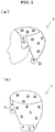
- FIG. 1 is a drawing for describing a basic configuration of a wig base according to one embodiment of the present invention.
- Fig.1 (a) illustrates a wig base 1 seen from the side and
- Fig.1(b) illustrates the wig base 1 seen obliquely from the rear respectively.
- the wig base 1 includes four portions as described below, and the wig base 1 is formed by stitching these portions together:
- a side base C which is similar to the above mentioned embodiment is also provided at a side located opposite to the side as shown in Fig. 1(a) .
- Each of the bases A to D can be formed by a net member, a resin material and another suitable material, which are generally used for a wig base. While it is not illustrated in the drawing, a wig product can be provided by planting artificial or natural hairs to the wig base 1.
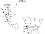
- a surface of the wig base illustrated in Fig.2 is a surface of the side which contacts a wearer's head (thus, inner surface side).
- the adjusting mechanism is formed by three of first to the third adjusting belts which can expand and contract elastically, a ring member 40 which makes these adjusting belts coupled together in a trifurcate shape.
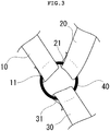
- Fig. 3 illustrates an enlarged view of a portion around the ring member 40 of Fig.2 in detail.
- One end of the first adjusting belt 10 is fixed to the side base C and another end of the first adjusting belt 10 has a loop portion 11 into which the ring member 40 is inserted.
- One end of the second adjusting belt 20 is fixed to the parietal base B and another end of the second adjusting belt 20 has a loop portion 21 into which the ring member 40 is inserted.
- One end of the third adjusting belt 30 is fixed to the nape portion base D and another end of the third adjusting belt 30 has a loop portion 31 into which the ring member 40 is inserted.
- the first to third adjusting belts are configured to have the loop portions 11, 21, 31 by folding back and stitching the other ends of the adjusting belts respectively. Then the ring member 40 is inserted into each of the loop portions, thereby forming the connecting portion in a trifurcate shape.
- any arbitrary way can be applied for specific embodiments.
- three of the other ends can be stitched together at one position in a trifurcate shape.
- the wig base can be adjusted finely so as to make the wig base fit a user's head with using a pull from three directions. Specifically, an adjustment in a circumferential direction of the head can be achieved by pulling with each other between the first adjusting belt 10 and the third adjusting belt 30. Additionally, an adjustment in a front-back direction of the head can also be achieved by applying a pulling up force by the second adjusting belt 20.
- the adjustment in a circumferential direction of the head If the adjustment in a circumferential direction of the head is performed, it can give a delicate effect to the front-back direction via the second adjusting belt 20. At the same time, if the adjustment in a front-back direction is performed, it can give a delicate effect to the circumferential direction via the first and third adjusting belts 10, 30. Accordingly, an extremely fine adjustment to the wig base can be achieved by applying "the three adjusting belts which can expand and contract" and "the connection at one place in a trifurcate shape", thereby realizing a very high fit feeling.
- each of the adjusting belts 10, 20, 30 and the ring member 40 are coupled together such that each of the adjusting belts 10, 20, 30 can slide freely along the circumferential direction of the ring member 40.
- the adjusting belts can flexibly move relative to the ring. Accordingly, a stress applied to the wig base 1 can effectively be released, (thus, a strain of the wig base can be released), and consequently a comfortable wearability can be achieved at a high level.
- a specific embodiment that the loop portions 11, 21, 31 are formed at the end of the adjusting belts is not limited to the illustrated embodiment, and any arbitrary configuration can be applied.
- a shape of the ring member 40 while a circular shape is preferable, an approximately triangle shape or others can also be applied.
- the first to third adjusting belts 10, 20, 30 are formed by flexible members and can expand and contract. Further, a total length of the second adjusting belt can be adjusted by providing a buckle 25 (thus, a reference length to which no external force is applied can be adjusted).
- an embodiment is not limited to the illustrated one. While only the second adjusting belt 20 has the buckle 25 and a total length thereof can be adjusted in the illustrated embodiment, a similar configuration can be applied to the other adjusting belts accordingly.
- a belt member 60 which extends along a circumferential direction of the head is stitched with the nape portion base D.
- the belt member 60 is stitched and connected with the nape portion base D at a plurality of locations at a certain interval.
- a plurality of inserting portions 65 (belt end connecting portions) are formed between a plurality of seams 61 in Fig.2 .
- a hooking member 35 (connecting portion) for inserting and fixing is connected at the end of the third adjusting belt 30. Accordingly, a relative position of the third adjusting belt 30 to the wig base can be changed by changing the inserting portions 65 into which the hooking member 35 is inserted. Therefore, a size of the wig base along a circumferential direction of the head can be changed. Thus, a size adjustment can be achieved in a large scale in comparison with the case of adjustment only with using an adjusting belt which can expand and contract.
- the configuration to achieve the position change is applied only to the third adjusting belt 30 as mentioned above, it is not limited thereto, and a similar configuration can be applied to the other adjusting belts.
- Fig 4 (a) illustrates an outline of this embodiment
- Fig 4(b) illustrates a partial exploded view for describing the construction thereof.
- a belt member 70 is connected (for example, stitched) along a periphery of the occipital base A.
- the first adjusting belt 10 and the third adjusting belt 30 are placed along the belt member 70, and the belt member 70 and the first adjusting belt 10 are coupled by placing a band 75a (flexible member) which can expand and contract around the belt member 70 and the first adjusting belt 10, and fixing both ends of the band 75a.
- the belt member 70 and the third adjusting belt 30 are coupled by placing a band 75b which can expand and contract around the belt member 70 and the third adjusting belt 30, and fixing both ends of the band 75b.
- the first adjusting belt 10 and the third adjusting belt 30 are engaged with the occipital base A via the band member 70.
- the bands 75a, 75b have flexibility. Therefore, when the first adjusting belt 10 and the third adjusting belt 30 are pulled upwardly by the second adjusting belt 20, the belts 10 , 30 can be displaced upwardly at some level, but they are prevented from being excessively displaced upwardly (refer to Fig.4c ). A degree of such effect can be set according to a material or configuration of the flexible bands 75a, 75b.
- the first adjusting belt 10 and the third adjusting belt 30 are displaced upwardly. If the first adjusting belt 10 and the third adjusting belt 30 are excessively displaced upwardly, a pressure is applied to the wearer's head, thereby lowering wearability. However, it can be prevented by using the bands 75a, 75b.
- the bands 75a, 75b are applied to both the first adjusting belt 10 and the third adjusting belt 30 in the illustrated embodiment, the band can be applied to either of them. It is not limited to the illustrated embodiment, and if the first adjusting belt 10 or the third adjusting belt 30 can be engaged with the occipital base A with using some flexible member, a similar effect will be obtained.
- an anti-slip coating can be applied to inner surfaces (thus, surfaces which contact a wearer's scalp) of the adjusting belts 10 to 30.
- the coating are provided for preventing slippage relative to the wearer's scalp, and the coating can be applied to all of the adjusting belts 10 to 30, and also to a part of the adjusting belts 10 to 30.
- silicone, urethane, latex or the like is generally used, it is not limited thereto as far as it has an effect to prevent slippage.
- an adjusting mechanism having a trifurcate shape can be covered with covering members 81, 82.
- the covering members 81, 82 are provided for lowering uncomfortable feeling due to the contact of the wearer's scalp with the ring member 40 or the like.
- the covering member 81 covers all of the ring member 40 and the first to third adjusting belts 10, 20, 30 in Fig.5 (a) .
- the covering member 82 covers only a portion around the ring member 40 in Fig.5(b) .
- An area covered with the covering member is not limited to the illustrated one, and it can be arbitrarily determined.
- three of the adjusting belts which forms the adjusting mechanism having a trifurcate shape are fixed to the parietal base B, the side base C and the nape portion base D.
- an essential feature of the present invention is to achieve a fine adjustment of the wig base with using a pull from three directions by three adjusting belts, such three adjusting belts can be fixed to any arbitrary three positions on the inner surface of the wig base, in addition to the illustrated embodiments.
- any arbitrary configuration can be adopted in addition to the illustrated embodiments in which the wig base is divided into four bases A, B, C, D.
- first adjusting belt 10 and the third adjusting belt 30 are placed along circumferential direction of the head, and the second adjusting belt 20 is extended upwardly as crossing the first and third adjusting belts 10, 30, "an adjustment in a circumferential direction of the head” and “an adjustment in a front-back direction of the head” can be achieved.
Landscapes
- Engineering & Computer Science (AREA)
- Textile Engineering (AREA)
- Orthopedics, Nursing, And Contraception (AREA)
Claims (10)
- Perückenbasis (1), wobei:
ein Ende eines ersten Einstellriemens (10), der sich ausdehnen und zusammenziehen kann, ein Ende eines zweiten Einstellriemens (20), der sich ausdehnen und zusammenziehen kann, und ein Ende eines dritten Einstellriemens (30), der sich ausdehnen und zusammenziehen kann, an beliebigen drei Positionen an einer Innenfläche der Perückenbasis (1) befestigt sind, dadurch gekennzeichnet, dass die anderen Enden der ersten bis dritten Einstellriemen (10, 20, 30) an einer Position in einer dreifach verzweigten Form angebracht sind. - Perückenbasis (1) nach Anspruch 1, wobei:
die drei Positionen zwei Positionen enthalten, die mit Abstand entlang einer Umfangsrichtung eines Kopfs eines Trägers liegen, und die verbleibende Position an einer inneren Stelle der Perückenbasis (1) liegt. - Perückenbasis (1) nach Anspruch 2, umfassend:eine Hinterkopfbasis (A), die den Hinterkopfbereich eines Kopfs eines Trägers bedeckt,eine Scheitelbasis (B), die mit der Hinterkopfbasis (A) verbunden ist, die eine Fläche von der Scheitelregion zum Vorderkopfbereich des Kopfs des Trägers bedeckt,eine Seitenbasis (C), die mit der Scheitelbasis (B) verbunden ist, die den Schläfenbereich des Kopfs des Trägers bedeckt,eine Nackenabschnittsbasis (D), die mit der Hinterkopfbasis (A) verbunden ist, die eine Halslinie des Trägers bedeckt,wobei:
das eine Ende des ersten Einstellriemens (10) an der Seitenbasis (C) befestigt ist, das eine Ende des zweiten Einstellriemens (20) an der Scheitelbasis (B) befestigt ist beziehungsweise das eine Ende des dritten Einstellriemens (30) an der Nackenabschnittsbasis (D) befestigt ist. - Perückenbasis (1) nach einem der Ansprüche 1 bis 3, wobei:
mindestens einer der ersten bis dritten Einstellriemen (10, 20, 30) so gestaltet ist, dass seine Gesamtlänge unter Verwendung einer Schließe (25) oder dergleichen eingestellt werden kann. - Perückenbasis (1) nach einem der Ansprüche 1 bis 4, wobei:Schlaufenabschnitte (11, 21, 31) an den jeweils anderen Enden der ersten bis dritten Einstellriemen (10, 20, 30) gebildet sind unddie anderen Enden an einer Position in der dreifach verzweigten Form angebracht sind, indem ein Ringelement (40) in die Schlaufenabschnitte (11, 21, 31) eingesetzt wird.
- Perückenbasis (1) nach Anspruch 3, wobei:
in der Nackenabschnittsbasis (D) eine Vielzahl von Riemenendverbindungsabschnittes (65) entlang einer Umfangsrichtung der Perückenbasis (1) vorgesehen sind und das eine Ende des dritten Einstellriemens (30) durch Anbringen eines Verbindungsabschnitts (35), der an dem einen Ende des dritten Einstellriemens (30) vorgehsehen ist, an einem der Riemenendverbindungsabschnitte (65) in seiner Position veränderbar an der Nackenabschnittsbasis (D) befestigt ist. - Perückenbasis (1) nach einem der Ansprüche 3 oder 6, wobei:
mindestens einer des ersten und dritten Einstellriemens (10, 30) mit der Hinterkopfbasis (A) durch ein flexibles Element (75a, 75b) in Eingriff ist. - Perückenbasis (1) nach einem der Ansprüche 1 bis 7, wobei:
eine rutschhemmende Beschichtung an einer Innenfläche zumindest eines der ersten bis dritten Einstellriemen (10, 20, 30) aufgebracht ist. - Perückenbasis (1) nach Anspruch 5, weiter umfassend ein Abdeckelement (81, 82), das mindestens einen Teil der ersten bis dritten Einstellriemen (10, 20, 30) und ein Ringelement (40) bedeckt.
- Perücke, die durch Einsetzen künstlicher Haare in die Perückenbasis (1) nach einem der Ansprüche 1 bis 9 gebildet wird.
Priority Applications (1)
| Application Number | Priority Date | Filing Date | Title |
|---|---|---|---|
| PL15779641T PL3132701T3 (pl) | 2014-04-18 | 2015-03-06 | Podstawa peruki zaopatrzona w rozgałęziający się w trzech kierunkach mechanizm regulacyjny |
Applications Claiming Priority (2)
| Application Number | Priority Date | Filing Date | Title |
|---|---|---|---|
| JP2014086652A JP5718507B1 (ja) | 2014-04-18 | 2014-04-18 | 3又の調整機構を備えたカツラベース |
| PCT/JP2015/056716 WO2015159608A1 (ja) | 2014-04-18 | 2015-03-06 | 3又の調整機構を備えたカツラベース |
Publications (3)
| Publication Number | Publication Date |
|---|---|
| EP3132701A1 EP3132701A1 (de) | 2017-02-22 |
| EP3132701A4 EP3132701A4 (de) | 2017-12-20 |
| EP3132701B1 true EP3132701B1 (de) | 2019-05-22 |
Family
ID=53277429
Family Applications (1)
| Application Number | Title | Priority Date | Filing Date |
|---|---|---|---|
| EP15779641.8A Active EP3132701B1 (de) | 2014-04-18 | 2015-03-06 | Perückenkappe mit dreifach verzweigtem einstellungsmechanismus |
Country Status (7)
| Country | Link |
|---|---|
| US (1) | US20160227863A1 (de) |
| EP (1) | EP3132701B1 (de) |
| JP (1) | JP5718507B1 (de) |
| DK (1) | DK3132701T3 (de) |
| ES (1) | ES2729877T3 (de) |
| PL (1) | PL3132701T3 (de) |
| WO (1) | WO2015159608A1 (de) |
Families Citing this family (1)
| Publication number | Priority date | Publication date | Assignee | Title |
|---|---|---|---|---|
| US20250255373A1 (en) * | 2024-02-08 | 2025-08-14 | Xuchang Longqi Electronic Commerce Co., LTD. | Wig and wearing method thereof |
Family Cites Families (25)
| Publication number | Priority date | Publication date | Assignee | Title |
|---|---|---|---|---|
| US373297A (en) * | 1887-11-15 | Louise f | ||
| US851384A (en) * | 1906-12-18 | 1907-04-23 | William Sleicher | Securing wigs in place. |
| US1127598A (en) * | 1910-11-08 | 1915-02-09 | Emma M Cunningham | Shirt-waist supporter. |
| DE337251C (de) * | 1920-10-27 | 1921-05-27 | Emanuel Gordon | Peruecke |
| FR86476E (de) * | 1963-05-16 | 1966-05-11 | ||
| US3645279A (en) * | 1970-05-19 | 1972-02-29 | Imrelon Inc | Wig construction employing a base of elastic and inelastic strips |
| CH554655A (de) * | 1971-06-16 | 1974-10-15 | Hair Contact Ag | Toupet oder peruecke. |
| US3734105A (en) * | 1972-01-05 | 1973-05-22 | Wagman & Comp Inc N | Capless wig |
| GB1388300A (en) * | 1972-08-17 | 1975-03-26 | Leslie N G South China Wigs Co | Wig cap |
| DE2326634A1 (de) * | 1973-05-25 | 1974-12-12 | Manfred Clauss | Peruecke |
| US4011598A (en) * | 1975-08-15 | 1977-03-15 | Kittie Anne Sherr | Bathing cap |
| JPH0532491Y2 (de) * | 1988-05-11 | 1993-08-19 | ||
| FR2775562B1 (fr) * | 1998-03-06 | 2000-05-26 | Nj Diffusion Sarl | Element souple antiderapant et perruque munie d'un tel element |
| US6105584A (en) * | 1998-07-13 | 2000-08-22 | Williams; Raymond | Size adjustable hair-enhancing cap |
| KR100301362B1 (ko) * | 1998-09-24 | 2001-12-31 | 박헌식 | 길이조절수단이부착된가발 |
| JP2000328336A (ja) * | 1999-05-25 | 2000-11-28 | Katsufumi Ito | かつらベース及びかつら |
| FR2807626B1 (fr) * | 2000-04-17 | 2002-09-20 | Nj Diffusion Sarl | Perruque ajustable a la forme de la tete de l'utilisateur |
| US20030029467A1 (en) * | 2001-08-10 | 2003-02-13 | Katon Juanita A. | Wig band |
| US6913024B2 (en) * | 2003-01-17 | 2005-07-05 | Love Wigs, Inc. | Wig cap having system of alteration darts |
| US20060130863A1 (en) * | 2004-12-20 | 2006-06-22 | Mun Chung | Stretchable wig |
| JP2007239153A (ja) * | 2006-03-10 | 2007-09-20 | Svenson:Kk | かつら |
| JP4949011B2 (ja) * | 2006-12-27 | 2012-06-06 | 株式会社アデランス | 全頭用かつらとその製造方法 |
| JP5016328B2 (ja) * | 2007-03-07 | 2012-09-05 | 株式会社アデランス | 自毛活用型かつら |
| JP5449609B1 (ja) * | 2013-10-04 | 2014-03-19 | 功二 手塚 | 補整機能付きウィッグ |
| US20160113342A1 (en) * | 2014-10-22 | 2016-04-28 | Eve Hair, Inc. | Half head wig |
-
2014
- 2014-04-18 JP JP2014086652A patent/JP5718507B1/ja active Active
-
2015
- 2015-03-06 US US15/029,810 patent/US20160227863A1/en not_active Abandoned
- 2015-03-06 WO PCT/JP2015/056716 patent/WO2015159608A1/ja not_active Ceased
- 2015-03-06 EP EP15779641.8A patent/EP3132701B1/de active Active
- 2015-03-06 ES ES15779641T patent/ES2729877T3/es active Active
- 2015-03-06 PL PL15779641T patent/PL3132701T3/pl unknown
- 2015-03-06 DK DK15779641.8T patent/DK3132701T3/da active
Non-Patent Citations (1)
| Title |
|---|
| None * |
Also Published As
| Publication number | Publication date |
|---|---|
| PL3132701T3 (pl) | 2019-10-31 |
| EP3132701A4 (de) | 2017-12-20 |
| EP3132701A1 (de) | 2017-02-22 |
| JP2015206133A (ja) | 2015-11-19 |
| ES2729877T3 (es) | 2019-11-06 |
| US20160227863A1 (en) | 2016-08-11 |
| JP5718507B1 (ja) | 2015-05-13 |
| WO2015159608A1 (ja) | 2015-10-22 |
| DK3132701T3 (da) | 2019-08-19 |
Similar Documents
| Publication | Publication Date | Title |
|---|---|---|
| JP7797294B2 (ja) | フックアンドループファスナを有するウォッチバンド | |
| CN109982591B (zh) | 女式内衣 | |
| EP3510881B1 (de) | Kleidungsstück mit körbchenteilen | |
| CN212260493U (zh) | 可调节体积的矫正文胸 | |
| WO2010098213A1 (ja) | 衣装 | |
| CN107708462B (zh) | 假发基底以及假发 | |
| US20150181948A1 (en) | Cotton bra | |
| KR101037337B1 (ko) | 주름식 길이조절이 가능한 치마 | |
| EP3132701B1 (de) | Perückenkappe mit dreifach verzweigtem einstellungsmechanismus | |
| JP5465518B2 (ja) | かつらベース | |
| HK1234288B (en) | Wig base provided with trifurcated adjustor mechanism | |
| JP2020012207A (ja) | ウィッグ | |
| HK1234288A1 (en) | Wig base provided with trifurcated adjustor mechanism | |
| JP6238342B2 (ja) | 全頭用かつら | |
| US20070226875A1 (en) | Headwear capable of maintaining shape of crown | |
| US1242118A (en) | Brassiere. | |
| JP5828022B1 (ja) | 略h形状の伸縮性領域を備えたカツラベース | |
| WO2017072876A1 (ja) | カップ部を有する衣類 | |
| KR200488491Y1 (ko) | 착탈형 차양이 구비된 모자 | |
| CN109744607A (zh) | 服装制品 | |
| KR101625044B1 (ko) | 슬림형 통가발 | |
| JP3121154U (ja) | 作業用長尺エプロン | |
| JP2016079515A (ja) | 簡易装着具付きかつら | |
| CN210299536U (zh) | 吊带模杯抹胸 | |
| KR101716791B1 (ko) | 브래지어 |
Legal Events
| Date | Code | Title | Description |
|---|---|---|---|
| STAA | Information on the status of an ep patent application or granted ep patent |
Free format text: STATUS: THE INTERNATIONAL PUBLICATION HAS BEEN MADE |
|
| PUAI | Public reference made under article 153(3) epc to a published international application that has entered the european phase |
Free format text: ORIGINAL CODE: 0009012 |
|
| STAA | Information on the status of an ep patent application or granted ep patent |
Free format text: STATUS: REQUEST FOR EXAMINATION WAS MADE |
|
| 17P | Request for examination filed |
Effective date: 20160603 |
|
| AK | Designated contracting states |
Kind code of ref document: A1 Designated state(s): AL AT BE BG CH CY CZ DE DK EE ES FI FR GB GR HR HU IE IS IT LI LT LU LV MC MK MT NL NO PL PT RO RS SE SI SK SM TR |
|
| AX | Request for extension of the european patent |
Extension state: BA ME |
|
| DAV | Request for validation of the european patent (deleted) | ||
| DAX | Request for extension of the european patent (deleted) | ||
| A4 | Supplementary search report drawn up and despatched |
Effective date: 20171116 |
|
| RIC1 | Information provided on ipc code assigned before grant |
Ipc: A41G 3/00 20060101AFI20171110BHEP |
|
| REG | Reference to a national code |
Ref country code: HK Ref legal event code: DE Ref document number: 1234288 Country of ref document: HK |
|
| RAP1 | Party data changed (applicant data changed or rights of an application transferred) |
Owner name: ADERANS COMPANY LIMITED |
|
| GRAP | Despatch of communication of intention to grant a patent |
Free format text: ORIGINAL CODE: EPIDOSNIGR1 |
|
| STAA | Information on the status of an ep patent application or granted ep patent |
Free format text: STATUS: GRANT OF PATENT IS INTENDED |
|
| INTG | Intention to grant announced |
Effective date: 20181214 |
|
| GRAS | Grant fee paid |
Free format text: ORIGINAL CODE: EPIDOSNIGR3 |
|
| GRAA | (expected) grant |
Free format text: ORIGINAL CODE: 0009210 |
|
| STAA | Information on the status of an ep patent application or granted ep patent |
Free format text: STATUS: THE PATENT HAS BEEN GRANTED |
|
| AK | Designated contracting states |
Kind code of ref document: B1 Designated state(s): AL AT BE BG CH CY CZ DE DK EE ES FI FR GB GR HR HU IE IS IT LI LT LU LV MC MK MT NL NO PL PT RO RS SE SI SK SM TR |
|
| REG | Reference to a national code |
Ref country code: GB Ref legal event code: FG4D |
|
| REG | Reference to a national code |
Ref country code: CH Ref legal event code: EP |
|
| REG | Reference to a national code |
Ref country code: IE Ref legal event code: FG4D |
|
| REG | Reference to a national code |
Ref country code: DE Ref legal event code: R096 Ref document number: 602015030843 Country of ref document: DE |
|
| REG | Reference to a national code |
Ref country code: AT Ref legal event code: REF Ref document number: 1134998 Country of ref document: AT Kind code of ref document: T Effective date: 20190615 |
|
| REG | Reference to a national code |
Ref country code: NL Ref legal event code: FP |
|
| REG | Reference to a national code |
Ref country code: SE Ref legal event code: TRGR |
|
| REG | Reference to a national code |
Ref country code: DK Ref legal event code: T3 Effective date: 20190816 |
|
| REG | Reference to a national code |
Ref country code: NO Ref legal event code: T2 Effective date: 20190522 |
|
| REG | Reference to a national code |
Ref country code: LT Ref legal event code: MG4D |
|
| PG25 | Lapsed in a contracting state [announced via postgrant information from national office to epo] |
Ref country code: FI Free format text: LAPSE BECAUSE OF FAILURE TO SUBMIT A TRANSLATION OF THE DESCRIPTION OR TO PAY THE FEE WITHIN THE PRESCRIBED TIME-LIMIT Effective date: 20190522 Ref country code: LT Free format text: LAPSE BECAUSE OF FAILURE TO SUBMIT A TRANSLATION OF THE DESCRIPTION OR TO PAY THE FEE WITHIN THE PRESCRIBED TIME-LIMIT Effective date: 20190522 Ref country code: HR Free format text: LAPSE BECAUSE OF FAILURE TO SUBMIT A TRANSLATION OF THE DESCRIPTION OR TO PAY THE FEE WITHIN THE PRESCRIBED TIME-LIMIT Effective date: 20190522 Ref country code: PT Free format text: LAPSE BECAUSE OF FAILURE TO SUBMIT A TRANSLATION OF THE DESCRIPTION OR TO PAY THE FEE WITHIN THE PRESCRIBED TIME-LIMIT Effective date: 20190922 Ref country code: AL Free format text: LAPSE BECAUSE OF FAILURE TO SUBMIT A TRANSLATION OF THE DESCRIPTION OR TO PAY THE FEE WITHIN THE PRESCRIBED TIME-LIMIT Effective date: 20190522 |
|
| REG | Reference to a national code |
Ref country code: ES Ref legal event code: FG2A Ref document number: 2729877 Country of ref document: ES Kind code of ref document: T3 Effective date: 20191106 |
|
| PG25 | Lapsed in a contracting state [announced via postgrant information from national office to epo] |
Ref country code: BG Free format text: LAPSE BECAUSE OF FAILURE TO SUBMIT A TRANSLATION OF THE DESCRIPTION OR TO PAY THE FEE WITHIN THE PRESCRIBED TIME-LIMIT Effective date: 20190822 Ref country code: RS Free format text: LAPSE BECAUSE OF FAILURE TO SUBMIT A TRANSLATION OF THE DESCRIPTION OR TO PAY THE FEE WITHIN THE PRESCRIBED TIME-LIMIT Effective date: 20190522 Ref country code: LV Free format text: LAPSE BECAUSE OF FAILURE TO SUBMIT A TRANSLATION OF THE DESCRIPTION OR TO PAY THE FEE WITHIN THE PRESCRIBED TIME-LIMIT Effective date: 20190522 Ref country code: GR Free format text: LAPSE BECAUSE OF FAILURE TO SUBMIT A TRANSLATION OF THE DESCRIPTION OR TO PAY THE FEE WITHIN THE PRESCRIBED TIME-LIMIT Effective date: 20190823 |
|
| REG | Reference to a national code |
Ref country code: AT Ref legal event code: MK05 Ref document number: 1134998 Country of ref document: AT Kind code of ref document: T Effective date: 20190522 |
|
| PG25 | Lapsed in a contracting state [announced via postgrant information from national office to epo] |
Ref country code: SK Free format text: LAPSE BECAUSE OF FAILURE TO SUBMIT A TRANSLATION OF THE DESCRIPTION OR TO PAY THE FEE WITHIN THE PRESCRIBED TIME-LIMIT Effective date: 20190522 Ref country code: RO Free format text: LAPSE BECAUSE OF FAILURE TO SUBMIT A TRANSLATION OF THE DESCRIPTION OR TO PAY THE FEE WITHIN THE PRESCRIBED TIME-LIMIT Effective date: 20190522 Ref country code: EE Free format text: LAPSE BECAUSE OF FAILURE TO SUBMIT A TRANSLATION OF THE DESCRIPTION OR TO PAY THE FEE WITHIN THE PRESCRIBED TIME-LIMIT Effective date: 20190522 Ref country code: AT Free format text: LAPSE BECAUSE OF FAILURE TO SUBMIT A TRANSLATION OF THE DESCRIPTION OR TO PAY THE FEE WITHIN THE PRESCRIBED TIME-LIMIT Effective date: 20190522 Ref country code: CZ Free format text: LAPSE BECAUSE OF FAILURE TO SUBMIT A TRANSLATION OF THE DESCRIPTION OR TO PAY THE FEE WITHIN THE PRESCRIBED TIME-LIMIT Effective date: 20190522 |
|
| REG | Reference to a national code |
Ref country code: DE Ref legal event code: R097 Ref document number: 602015030843 Country of ref document: DE |
|
| PG25 | Lapsed in a contracting state [announced via postgrant information from national office to epo] |
Ref country code: SM Free format text: LAPSE BECAUSE OF FAILURE TO SUBMIT A TRANSLATION OF THE DESCRIPTION OR TO PAY THE FEE WITHIN THE PRESCRIBED TIME-LIMIT Effective date: 20190522 Ref country code: IT Free format text: LAPSE BECAUSE OF FAILURE TO SUBMIT A TRANSLATION OF THE DESCRIPTION OR TO PAY THE FEE WITHIN THE PRESCRIBED TIME-LIMIT Effective date: 20190522 |
|
| PLBE | No opposition filed within time limit |
Free format text: ORIGINAL CODE: 0009261 |
|
| STAA | Information on the status of an ep patent application or granted ep patent |
Free format text: STATUS: NO OPPOSITION FILED WITHIN TIME LIMIT |
|
| PG25 | Lapsed in a contracting state [announced via postgrant information from national office to epo] |
Ref country code: TR Free format text: LAPSE BECAUSE OF FAILURE TO SUBMIT A TRANSLATION OF THE DESCRIPTION OR TO PAY THE FEE WITHIN THE PRESCRIBED TIME-LIMIT Effective date: 20190522 |
|
| 26N | No opposition filed |
Effective date: 20200225 |
|
| PGFP | Annual fee paid to national office [announced via postgrant information from national office to epo] |
Ref country code: GB Payment date: 20200317 Year of fee payment: 6 Ref country code: NL Payment date: 20200326 Year of fee payment: 6 Ref country code: DK Payment date: 20200324 Year of fee payment: 6 Ref country code: DE Payment date: 20200309 Year of fee payment: 6 Ref country code: NO Payment date: 20200310 Year of fee payment: 6 Ref country code: SE Payment date: 20200310 Year of fee payment: 6 Ref country code: PL Payment date: 20200219 Year of fee payment: 6 |
|
| PG25 | Lapsed in a contracting state [announced via postgrant information from national office to epo] |
Ref country code: SI Free format text: LAPSE BECAUSE OF FAILURE TO SUBMIT A TRANSLATION OF THE DESCRIPTION OR TO PAY THE FEE WITHIN THE PRESCRIBED TIME-LIMIT Effective date: 20190522 |
|
| PGFP | Annual fee paid to national office [announced via postgrant information from national office to epo] |
Ref country code: BE Payment date: 20200226 Year of fee payment: 6 |
|
| PGFP | Annual fee paid to national office [announced via postgrant information from national office to epo] |
Ref country code: FR Payment date: 20200226 Year of fee payment: 6 |
|
| PGFP | Annual fee paid to national office [announced via postgrant information from national office to epo] |
Ref country code: ES Payment date: 20200401 Year of fee payment: 6 |
|
| PG25 | Lapsed in a contracting state [announced via postgrant information from national office to epo] |
Ref country code: MC Free format text: LAPSE BECAUSE OF FAILURE TO SUBMIT A TRANSLATION OF THE DESCRIPTION OR TO PAY THE FEE WITHIN THE PRESCRIBED TIME-LIMIT Effective date: 20190522 |
|
| REG | Reference to a national code |
Ref country code: CH Ref legal event code: PL |
|
| PG25 | Lapsed in a contracting state [announced via postgrant information from national office to epo] |
Ref country code: LU Free format text: LAPSE BECAUSE OF NON-PAYMENT OF DUE FEES Effective date: 20200306 |
|
| PG25 | Lapsed in a contracting state [announced via postgrant information from national office to epo] |
Ref country code: IE Free format text: LAPSE BECAUSE OF NON-PAYMENT OF DUE FEES Effective date: 20200306 Ref country code: LI Free format text: LAPSE BECAUSE OF NON-PAYMENT OF DUE FEES Effective date: 20200331 Ref country code: CH Free format text: LAPSE BECAUSE OF NON-PAYMENT OF DUE FEES Effective date: 20200331 |
|
| REG | Reference to a national code |
Ref country code: DE Ref legal event code: R119 Ref document number: 602015030843 Country of ref document: DE |
|
| REG | Reference to a national code |
Ref country code: NO Ref legal event code: MMEP |
|
| REG | Reference to a national code |
Ref country code: DK Ref legal event code: EBP Effective date: 20210331 |
|
| REG | Reference to a national code |
Ref country code: NL Ref legal event code: MM Effective date: 20210401 |
|
| GBPC | Gb: european patent ceased through non-payment of renewal fee |
Effective date: 20210306 |
|
| REG | Reference to a national code |
Ref country code: BE Ref legal event code: MM Effective date: 20210331 |
|
| PG25 | Lapsed in a contracting state [announced via postgrant information from national office to epo] |
Ref country code: NL Free format text: LAPSE BECAUSE OF NON-PAYMENT OF DUE FEES Effective date: 20210401 Ref country code: NO Free format text: LAPSE BECAUSE OF NON-PAYMENT OF DUE FEES Effective date: 20210331 Ref country code: DE Free format text: LAPSE BECAUSE OF NON-PAYMENT OF DUE FEES Effective date: 20211001 Ref country code: FR Free format text: LAPSE BECAUSE OF NON-PAYMENT OF DUE FEES Effective date: 20210331 Ref country code: GB Free format text: LAPSE BECAUSE OF NON-PAYMENT OF DUE FEES Effective date: 20210306 Ref country code: SE Free format text: LAPSE BECAUSE OF NON-PAYMENT OF DUE FEES Effective date: 20210307 |
|
| PG25 | Lapsed in a contracting state [announced via postgrant information from national office to epo] |
Ref country code: DK Free format text: LAPSE BECAUSE OF NON-PAYMENT OF DUE FEES Effective date: 20210331 |
|
| REG | Reference to a national code |
Ref country code: ES Ref legal event code: FD2A Effective date: 20220523 |
|
| PG25 | Lapsed in a contracting state [announced via postgrant information from national office to epo] |
Ref country code: MT Free format text: LAPSE BECAUSE OF FAILURE TO SUBMIT A TRANSLATION OF THE DESCRIPTION OR TO PAY THE FEE WITHIN THE PRESCRIBED TIME-LIMIT Effective date: 20190522 Ref country code: CY Free format text: LAPSE BECAUSE OF FAILURE TO SUBMIT A TRANSLATION OF THE DESCRIPTION OR TO PAY THE FEE WITHIN THE PRESCRIBED TIME-LIMIT Effective date: 20190522 |
|
| PG25 | Lapsed in a contracting state [announced via postgrant information from national office to epo] |
Ref country code: MK Free format text: LAPSE BECAUSE OF FAILURE TO SUBMIT A TRANSLATION OF THE DESCRIPTION OR TO PAY THE FEE WITHIN THE PRESCRIBED TIME-LIMIT Effective date: 20190522 Ref country code: IS Free format text: LAPSE BECAUSE OF FAILURE TO SUBMIT A TRANSLATION OF THE DESCRIPTION OR TO PAY THE FEE WITHIN THE PRESCRIBED TIME-LIMIT Effective date: 20190922 |
|
| PG25 | Lapsed in a contracting state [announced via postgrant information from national office to epo] |
Ref country code: ES Free format text: LAPSE BECAUSE OF NON-PAYMENT OF DUE FEES Effective date: 20210307 Ref country code: BE Free format text: LAPSE BECAUSE OF NON-PAYMENT OF DUE FEES Effective date: 20210331 |
|
| PG25 | Lapsed in a contracting state [announced via postgrant information from national office to epo] |
Ref country code: PL Free format text: LAPSE BECAUSE OF NON-PAYMENT OF DUE FEES Effective date: 20210306 |