EP3132666B1 - Mähmaschine - Google Patents
Mähmaschine Download PDFInfo
- Publication number
- EP3132666B1 EP3132666B1 EP16184270.3A EP16184270A EP3132666B1 EP 3132666 B1 EP3132666 B1 EP 3132666B1 EP 16184270 A EP16184270 A EP 16184270A EP 3132666 B1 EP3132666 B1 EP 3132666B1
- Authority
- EP
- European Patent Office
- Prior art keywords
- transverse conveyor
- casing
- mowing machine
- machine according
- mower
- Prior art date
- Legal status (The legal status is an assumption and is not a legal conclusion. Google has not performed a legal analysis and makes no representation as to the accuracy of the status listed.)
- Active
Links
Images




Classifications
-
- A—HUMAN NECESSITIES
- A01—AGRICULTURE; FORESTRY; ANIMAL HUSBANDRY; HUNTING; TRAPPING; FISHING
- A01D—HARVESTING; MOWING
- A01D43/00—Mowers combined with apparatus performing additional operations while mowing
- A01D43/10—Mowers combined with apparatus performing additional operations while mowing with means for crushing or bruising the mown crop
-
- A—HUMAN NECESSITIES
- A01—AGRICULTURE; FORESTRY; ANIMAL HUSBANDRY; HUNTING; TRAPPING; FISHING
- A01D—HARVESTING; MOWING
- A01D57/00—Delivering mechanisms for harvesters or mowers
-
- A—HUMAN NECESSITIES
- A01—AGRICULTURE; FORESTRY; ANIMAL HUSBANDRY; HUNTING; TRAPPING; FISHING
- A01D—HARVESTING; MOWING
- A01D57/00—Delivering mechanisms for harvesters or mowers
- A01D57/30—Rotating attachments for forming windrows
-
- G—PHYSICS
- G11—INFORMATION STORAGE
- G11B—INFORMATION STORAGE BASED ON RELATIVE MOVEMENT BETWEEN RECORD CARRIER AND TRANSDUCER
- G11B9/00—Recording or reproducing using a method not covered by one of the main groups G11B3/00 - G11B7/00; Record carriers therefor
- G11B9/12—Recording or reproducing using a method not covered by one of the main groups G11B3/00 - G11B7/00; Record carriers therefor using near-field interactions; Record carriers therefor
- G11B9/14—Recording or reproducing using a method not covered by one of the main groups G11B3/00 - G11B7/00; Record carriers therefor using near-field interactions; Record carriers therefor using microscopic probe means, i.e. recording or reproducing by means directly associated with the tip of a microscopic electrical probe as used in Scanning Tunneling Microscopy [STM] or Atomic Force Microscopy [AFM] for inducing physical or electrical perturbations in a recording medium; Record carriers or media specially adapted for such transducing of information
Definitions
- the present invention relates to a mower with at least one mower and a transverse conveyor downstream of the mower for transversely conveying the crop cut by the mower, the transverse conveyor in particular having a transverse screw conveyor which can be driven in rotation about a horizontal screw axis essentially transversely to the direction of travel.
- cross conveyors are driven behind mowers so that the mown crop is not spread out on the ground directly behind the mower, but instead the crop is deposited in a swath to the side of the mowed track of the mower.
- the harvested crop can thereby be deposited in a common swath.
- Such cross conveyors are known, for example, in the form of cross conveyor belts on which the mown crop is deposited from the mower in order to be conveyed across and deposited next to the mower on the ground, cf. for example DE 10 2005 050 157 A1 .
- a cross conveyor screw as a cross conveyor, cf. for example EP 1 111 985 B1 or GB 20 88 684 .
- a harvesting machine which comprises a mower and a transverse conveyor downstream of the mower in the form of a transverse screw conveyor that takes over the crop cut by the mower and conveys it transversely to the direction of travel in order to deposit the crop in a swath to the side of the mower.
- conditioners are occasionally provided between the mower and the cross conveyor in order to break up the cut crop so that the crop can be dried more quickly.
- Such conditioners can comprise conditioning rollers rotating in opposite directions, so that the crop is conveyed through between them and thereby squeezed and bent.
- such conditioners can also comprise only one high-speed flail roller, the radially protruding flails of which strike the cut crop and thereby bend it and throw it over to the cross conveyor.
- the EP 1 111 985 B1 suggests opening up the cut crop with a conditioning roller and throwing it onto an upper sector of a transverse screw conveyor, with the transverse screw conveyor rotating in the same direction as the conditioning roller in order to approximately maintain the acceleration given to the crop or to increase the crop at the transfer Braking the cross conveyor as little as possible.
- the present invention is based on the object of creating an improved mower of the type mentioned which avoids the disadvantages of the prior art and trains the latter in an advantageous manner.
- a light-weight and compact arrangement should preferably be used to achieve reliable transverse conveying while at the same time sufficiently opening up and conditioning the crop.
- the cross auger is arranged directly behind the mower and the mowed material is transferred from the mower directly to the cross conveyor.
- the crop cut by the mower arrives untreated, i.e. without any further action of a conditioner directly on the cross conveyor, which is advantageously designed as a cross conveyor screw, which conveys the transferred crop essentially across the direction of travel and at the same time unlocks and conditions it.
- the total weight of the mower combination can be considerably reduced and the required installation space can be significantly reduced when viewed in the direction of travel, which on the one hand facilitates the adaptation to the ground, for example when driving over bumps and on the other hand, the attachment to one Simplified tractor, especially with front attachment to the tractor.
- the cross conveyor can have a trough-shaped jacket that surrounds the cross conveyor screw and has an inlet opening towards the front of the mower through which the crop cut by the mower enters the interior of the jacket and / or into the conveying space between the jacket and Cross auger can get.
- the casing can connect with a lower inlet edge that delimits the inlet opening at the bottom to an approximately plate-shaped sliding body which supports the cutting rotors on the floor and which can be designed, for example, as a sliding plate under a cutting drum or as a cutter bar.
- the lower inlet edge of the above-mentioned casing can be connected essentially directly or directly to a rear edge of the above-mentioned plate-shaped sliding body, so that the cut crop gets directly into the conveying space within the casing and transfer problems between mower and cross conveyor can be largely avoided.
- the casing can be connected with its lower inlet edge without a gap to a rear end section of said sliding body.
- the lower entry edge of the casing of the transverse conveyor can be arranged approximately at the level of the cutting tools of the mower.
- the cutting tools mentioned can be cutting knives driven in rotation about an upright axis.
- the mower can comprise a plurality of cutting rotors which are arranged next to one another transversely to the direction of travel and which each revolve around upright rotor axes.
- the mower can be designed as a disc mower or a drum mower, with the transverse auger, especially in combination with disc mowers, in which rotating cutter disks are arranged next to one another on a cutter bar, forms a particularly compact mower combination that works trouble-free during transfer, especially when the lower inlet edge is located of the jacket around the cross auger connects to the rear end of the cutter bar on which the rotating cutter discs are mounted.
- the shell surrounding the transverse screw conveyor can form a half-shell in a further development of the invention, which, viewed in the circumferential direction, encloses the transverse screw conveyor over an angular range of approximately 3/4 ⁇ to 5/4 ⁇ , with the half-shell-shaped shell in a further development of the invention in a rear lower and a rear upper quadrant may extend around the cross auger.
- the half-shell-shaped jacket can extend around the transverse auger in an area which - when the mower is arranged on the 9 o'clock side of the transverse auger - begins at around 6 a.m. to 8 a.m. and ends at around 12 p.m. to 3 a.m.
- the bowl-shaped jacket can also be useful to make the bowl-shaped jacket wider or narrower, i.e. to enclose the transverse screw conveyor over a larger or smaller angular range in the circumferential direction.
- the aforementioned extension or design of the jacket forms an advantageous compromise for a large number of different crops.
- the jacket can be shaped in such a way that, viewed in the circumferential direction, an approximately constant gap dimension is provided between the transverse screw conveyor and the inner jacket surface of the surrounding jacket.
- an approximately constant gap dimension is provided between the transverse screw conveyor and the inner jacket surface of the surrounding jacket.
- the cross conveyor can do without widening the jacket or the conveying space provided between jacket and cross conveyor screw in the area of the inlet where the cut crop is fed to the cross conveyor, so that when the crop enters the cross conveyor there is a relatively strong There is a conditioning effect and the cut crop is sufficiently opened up when it comes into engagement with the helix of the transverse screw conveyor and is pulled or pressed by this into the conveyor gap between the jacket and the transverse screw conveyor.
- the transverse screw conveyor can have a direction of rotation in which a fictitious point on the transverse screw conveyor rotates from top to front downward, so that the cut crop is pulled or pressed at the lower inlet edge of the jacket between the jacket and the cross conveyor screw becomes.
- the front, lower quadrant of the transverse screw conveyor can advantageously serve as an inlet area in which the cut crop reaches the transverse screw conveyor or is drawn in between the transverse screw conveyor and jacket. In this way, a sufficient conditioning effect can be achieved with problem-free transfer of the harvested crop.
- the jacket can have a scraper bar protruding from its inner jacket surface, which extends approximately in the longitudinal direction through the conveyor channel between the cross conveyor screw and the inner jacket surface.
- a plurality of such wiper strips can be provided, which are spaced apart from one another in the circumferential direction and extend in the longitudinal direction through the said conveying space, wherein the plurality of wiper strips can be arranged parallel to one another.
- Said scraper strips can run parallel to the screw axis, but can also run at a slight angle to the screw axis so that they extend in a slightly helical manner through the conveying space or gap between the inner surface of the jacket and the transverse screw conveyor.
- the cut crop also works off these scraper bars during the transverse conveyance, so that there is increased unlocking and thus the desired conditioning effect.
- the wiper strips mentioned support the transverse conveying effect.
- the cross conveyor can form an assembly that is separate from the mower can be releasably attached to the support frame of the mower, in particular can be suspended in a pendulum fashion together with the mower about a horizontal support arm axis pointing in the direction of travel.
- quick connectors for example in the form of a plug connection and / or a quick coupling, can be provided between the mower or its support frame and the cross conveyor in order to enable easy disassembly or assembly.
- the mower 1 can comprise several mower units that can be attached to a tractor 2, the in Fig. 1 Drawn embodiment has a front mower unit 3 and two rear mower units 4 and 5, which are arranged offset to one another, but slightly overlapping with regard to their mowing width and complement one another.
- the front mower unit 3 is positioned in the middle of the tractor 2, while the two rear mower units 4 and 5 are positioned next to the tractor 2 so as to cantilever laterally.
- the two rear mower units 4 and 5 can each be provided with a cross conveyor 7 in order to be able to place the crop mowed with the rear mower units 4 and 5 transversely offset, in particular towards the center laterally next to the respective mower unit in a swath 20, so that, for example, the allows mown crops to be deposited by all three mower units 3, 4 and 5 in a common central swath.
- the front mower unit 3 can also be provided with such a cross conveyor in order to then combine, for example, cut crops from several tramlines in 2 or 3 swaths.
- each of the mentioned mower units can comprise a mower 6, which has several cutting rotors 17 arranged next to one another, which can each be driven in rotation about an upright rotor axis so that the rotating cutting tools 19 of the cutting rotors 17 cut the crop close to the ground.
- the mentioned cutting rotors 17 can here, as shown in the figures, be designed in the shape of a disk and on an approximately plate-shaped one extending transversely to the direction of travel
- Sliding body 18 can be arranged in the form of a cutter bar, which protects the mentioned cutting rotors 17 from contact with the ground and supports it against it.
- Said cutter bar can be suspended together with the cutting rotor 17 on a mower frame 21, which in turn is mounted on an attachment device by means of which the respective mower 6 can be attached to the tractor 2.
- the mentioned mower frame 21 can be suspended from a support arm so as to swing about a horizontal axis pointing in the direction of travel, like this Fig. 1 shows.
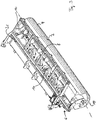
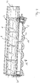
- a transverse conveyor 7 which consists of a transverse screw conveyor 8, which is surrounded on the circumference by a cylindrical jacket 9. Said transverse screw conveyor 8 can be driven in rotation about a screw axis 15, which extends horizontally across the direction of travel 16. How Fig. 6 shows, the said transverse screw conveyor 8 is arranged in terms of height so that a lower sector of the transverse screw conveyor 8 is arranged approximately at the level of the cutting tools 19 of the mower 6, the said transverse screw conveyor 8 extending approximately parallel to the longitudinal extent of the cutter bar along which the Cutting rotors 17 are arranged side by side.
- the transverse screw conveyor 8 can have a conveyor spiral in a manner known per se, which extends helically around a cylindrical core body of the transverse screw conveyor 8.
- the shell 9 enclosing the transverse auger 8 at least in sections is designed to be open on a front side of the transverse auger 8, ie a side of the transverse auger 8 facing the mower 6, so that cut crops coming from the mower 6 into the conveying area via the inlet opening 10 of the shell 9 formed by this the transverse screw conveyor 8 can reach.
- said inlet opening 10 extends essentially over the entire width of the mower 6 and opens essentially the entire front side of the transverse screw conveyor 8 to the mower 6 so that the crop can be given to the cross auger 8 here.
- the transverse screw conveyor 8 itself extends laterally in terms of width beyond the mower 6, the area protruding laterally over the mower 6 is also enclosed at the front by the jacket 9, cf. Fig. 2 .
- the jacket 9 or the transverse conveyor 7 has a deposit opening in order to deposit the transversely conveyed crop on the ground next to the mower 6, cf. Fig. 1 .
- Said deposit opening 22 is formed by the open end cross section of the jacket 9, cf. Fig. 2 .
- the jacket 9 of the transverse conveyor 7 closes with a lower inlet edge 12, which delimits said inlet opening 10 at its lower end, essentially directly to a rear end portion of the sliding body 18 in the form of the cutter bar, said inlet edge 12 being approximately level the cutting tools 19 of the cutting rotors 17 is arranged.
- Said inlet edge 12 is here approximately at about 7 o'clock of the transverse auger 8, if the viewing direction is selected so that the mower 6 is on the 9 o'clock side of the transverse auger 8, cf. Fig. 6 .
- the jacket 9 extends from the mentioned inlet edge 12 circumferentially around the rear quadrants of the transverse screw conveyor 8 up to an area around 1 o'clock, so that the jacket 9 is approximately half-shell-shaped overall. Between the inner circumferential side 9i of the shell 9 and the transverse screw conveyor 8, a semicircular conveyor gap 13 is formed, the gap dimension of which is selected to be approximately constant when viewed in the circumferential direction, cf. Fig. 6 .
- the in Fig. 6 The vertical arrangement of the transverse auger 8 shown immediately behind the mower 6 forms a lower front quadrant 23 of the transverse auger 8, which extends from about 9 a.m. to about 6 a.m., the inlet area 11 of the transverse auger 8, in which the cut crop coming from the mower 6 is thrown or pressed against the transverse screw conveyor 8.
- the transverse screw conveyor 8 advantageously has a direction of rotation which allows the front side of the transverse screw conveyor 8 facing the mower 6 to run downward - according to FIG Fig. 6 so counterclockwise. A fictitious point on the transverse screw conveyor 8 runs from its top to the front and then downwards.
- the cut crop arrives at the lower opening area of the shell 9 at the inlet edge 12 between the transverse screw conveyor 8 and the inner lateral surface of the shell 9 and is conveyed away in the conveyor gap 13 by the conveying movement of the transverse screw conveyor 8 transversely to the direction of travel 16.
- the stripper bars 14 support the axial movement of the crop and also help with the desired conditioning of the crop, since the crop is also processed on the said stripper bars 14.
- the wiper strips 14 can advantageously be arranged uniformly spaced over the circumferential area of the transverse screw conveyor 8 enclosed by the jacket 9.
- the cross conveyor 7 advantageously forms a detachable assembly that can be releasably attached to the mower frame 21 of the mower 6. In this way, on the one hand, a very compact arrangement can be achieved, on the other hand, an exact height positioning of the transverse conveyor 7 relative to the mower 6 is achieved, which ensures problem-free transfer of the crop.
- quick connection means that can advantageously be operated without tools can be provided between the cross conveyor 7 and the mower 6. Accordingly, the mower 6 can optionally be operated with or without a downstream transverse conveyor 7.
Landscapes
- Life Sciences & Earth Sciences (AREA)
- Environmental Sciences (AREA)
- Harvester Elements (AREA)
Description
- Die vorliegende Erfindung betrifft eine Mähmaschine mit zumindest einem Mähwerk sowie einem dem Mähwerk nachgeordneten Querförderer zum Querfördern des vom Mähwerk geschnittenen Ernteguts, wobei der Querförderer insbesondere eine Querförderschnecke aufweist, die um eine liegende Schneckenachse im Wesentlichen quer zur Fahrtrichtung rotatorisch antreibbar ist.
- Bisweilen werden hinter Mähwerken Querförderer gefahren, um das abgemähte Erntegut nicht ausgebreitet unmittelbar hinter dem Mähwerk am Boden liegen zu lassen, sondern das Erntegut in einem Schwad seitlich neben der bemähten Spur des Mähwerks abzulegen. Insbesondere bei mehreren nebeneinander oder gestaffelt hintereinander angeordneten Mähwerken kann das Erntegut hierdurch in einem gemeinsamen Schwad abgelegt werden. Derartige Querförderer sind beispielsweise in Form von Querförderbändern bekannt, auf die das gemähte Erntegut vom Mähwerk her abgelegt wird, um quergefördert und neben dem Mähwerk am Boden abgelegt zu werden, vgl. beispielsweise
DE 10 2005 050 157 A1 . Zum anderen wurde bereits vorgeschlagen, als Querförderer eine Querförderschnecke zu verwenden, vgl. beispielsweiseEP 1 111 985 B1 oderGB 20 88 684 - Aus der Schrift
US 6,662,539 B1 ist eine Erntemaschine bekannt, die ein Mähwerk und einen dem Mähwerk nachgeordneten Querförderer in Form einer Querförderschnecke umfasst, die das vom Mähwerk geschnittene Erntegut übernimmt und quer zur Fahrtrichtung fördert, um das Erntegut in einem Schwad seitlich neben dem Mähwerk abzulegen. - Dabei werden zwischen dem Mähwerk und dem Querförderer gelegentlich Konditionierer vorgesehen, um das abgemähte Erntegut aufzuschließen, so dass eine schnellere Trocknung des Ernteguts erreicht werden kann. Solche Konditionierer können gegenläufig umlaufende Konditionierwalzen umfassen, so dass das Erntegut zwischen ihnen hindurchgefördert und dabei gequetscht und geknickt wird. Andererseits können solche Konditionierer auch nur eine schnell laufende Schlegelwalze umfassen, deren radial abstehende Schlegel das geschnittene Erntegut anschlagen und dabei knicken und im Wurf an den Querförderer übergeben. Beispielsweise die
EP 1 111 985 B1 schlägt vor, das geschnittene Erntegut mit einer Konditionierwalze aufzuschließen und auf einen oberen Sektor einer Querförderschnecke zu werfen, wobei die Querförderschnecke in derselben Richtung wie die Konditionierwalze umlaufen soll, um die dem Erntegut einmal erteilte Beschleunigung annähernd zu erhalten bzw. das Erntegut bei der Übergabe auf den Querförderer so wenig wie möglich abzubremsen. - Wenn solche Konditionierer und Querförderer zusammen verwendet werden, ist einerseits eine Bodenanpassung nicht ganz einfach zu erreichen, da der Konditionierer relativ zum Mähwerk und der Querförderer wiederum relativ zum Konditionierer in einem bestimmten Höhenfenster angeordnet werden muss, um eine Übergabe des Ernteguts sicherzustellen. Die Mähwerks-/Konditionierer-/Querförderer-Einheit bildet eine in Fahrtrichtung betrachtet recht lange Baugruppe, die beim Überfahren von Bodenwellen aufgrund der genannten Höhenversatzproblematik der einzelnen Bestandteile relativ zueinander eine Bodenanpassung nur schwierig zulässt. Zum anderen ergeben sich aufgrund der recht großen Baugruppenlänge Platzprobleme und recht große Auskraglängen, die den Anbau an einen Schlepper erschweren. Insbesondere beim Frontanbau führt dies oftmals dazu, dass keine Querförderer verwendet werden können, da bei noch beherrschbarer Auskraglänge der Platz zwischen Mähwerk und Bug des Schleppers für einen Konditionierer und einen Querförderer zu klein ist.
- Der vorliegenden Erfindung liegt die Aufgabe zugrunde, eine verbesserte Mähmaschine der genannten Art zu schaffen, die Nachteile des Standes der Technik vermeidet und Letzteren in vorteilhafter Weise weiterbildet. Vorzugsweise soll mit einer leichtgewichtigen und kleinbauenden Anordnung eine verlässliche Querförderung bei gleichzeitig ausreichendem Aufschließen und Konditionieren des Ernteguts erreicht werden.
- Erfindungsgemäß wird diese Aufgabe durch eine Mähmaschine gemäß Anspruch 1 gelöst. Bevorzugte Ausgestaltungen sind Gegenstand der abhängigen Ansprüche.
- Es wird vorgeschlagen, die Querförderschnecke gleichzeitig als Konditionierer und Querförderer zu verwenden. Überraschenderweise reicht die Walk-, Biege-, Knick- und Pressarbeit an den Schneckenschaufeln aus, um das Erntegut ausreichend aufzuschließen und den Trocknungsprozess in der gewünschten Weise zu beschleunigen, so dass auf separate Konditioniererwalzen zwischen Querförderer und Mähwerk verzichtet werden kann. Erfindungsgemäß wird der Querförderer unmittelbar hinter dem Mähwerk angeordnet und das gemähte Gut von dem Mähwerk direkt an den Querförderer übergeben. Das vom Mähwerk geschnittene Erntegut gelangt unbehandelt, d.h. ohne weitergehende Einwirkung eines Konditionierers direkt auf den Querförderer, der vorteilhafterweise als Querförderschnecke ausgebildet ist, welche das übergebene Erntegut im Wesentlichen quer zur Fahrtrichtung abfördert und dabei gleichzeitig aufschließt und konditioniert. Hierdurch kann gegenüber den vorbekannten Mähwerkskombinationen, die zwischen Querförderer und Mähwerk noch separate Konditioniererwalzen vorsehen, das Gesamtgewicht der Mähwerkskombination beträchtlich reduziert und der benötigte Bauraum in Fahrtrichtung betrachtet deutlich verkleinert werden, was einerseits die Bodenanpassung beispielsweise beim Überfahren von Bodenwellen erleichtert und andererseits den Anbau an einem Schlepper vereinfacht, insbesondere bei Frontanbau am Schlepper.
- In Weiterbildung der Erfindung kann der Querförderer einen wannenförmigen Mantel besitzen, der die Querförderschnecke umgibt und nach vorne zum Mähwerk hin eine Einlauföffnung besitzt, durch die das vom Mähwerk geschnittene Erntegut in den Innenraum des Mantels und/oder in den Förderraum zwischen Mantel und Querförderschnecke gelangen kann. Vorteilhafterweise kann der Mantel mit einer unteren Einlaufkante, die die genannte Einlauföffnung nach unten hin begrenzt, an einen die Schneidrotoren am Boden abstützenden, näherungsweise plattenförmigen Gleitkorpus anschließen, der beispielsweise als Gleitteller unter einer Schneidtrommel oder als Mähbalken ausgebildet sein kann. Insbesondere kann der genannte Mantel mit seiner unteren Einlaufkante im Wesentlichen unmittelbar bzw. direkt an eine Hinterkante des genannten plattenförmigen Gleitkorpus anschließen, so dass das geschnittene Erntegut unmittelbar in den Förderraum innerhalb des Mantels gerät und Übergabeprobleme zwischen Mähwerk und Querförderer weitestgehend vermieden werden können. Gemäß einer vorteilhaften Weiterbildung der Erfindung kann der Mantel mit seiner unteren Einlaufkante spaltfrei mit einem hinteren Endabschnitt des genannten Gleitkorpus verbunden sein. Hierdurch kann einerseits eine minimale Baulänge in Fahrtrichtung erzielt und andererseits das Erntegut ohne Übergabeverluste oder Übergabestauungen auf den Querförderer gegeben werden.
- Um einen direkten, weitgehend umlenkungsfreien Einlauf des geschnittenen Ernteguts in den Querförderer zu ermöglichen, kann in Weiterbildung der Erfindung die untere Einlaufkante des Mantels des Querförderers näherungsweise auf Höhe der Schneidwerkzeuge des Mähwerks angeordnet sein. Die genannten Schneidwerkzeuge können um eine aufrechte Achse umlaufend angetriebene Schneidmesser sein. Alternativ oder zusätzlich kann das Mähwerk eine Mehrzahl von Schneidrotoren umfassen, die quer zur Fahrtrichtung nebeneinander liegend angeordnet sind und um jeweils aufrechte Rotorachsen umlaufen. Das Mähwerk kann dabei als Scheibenmähwerk oder als Trommelmähwerk ausgebildet sein, wobei die Querförderschnecke gerade in Kombination mit Scheibenmähwerken, bei denen auf einem Mähbalken nebeneinander umlaufende Messerscheiben angeordnet sind, eine besonders kompakte, bei der Übergabe störungsfrei arbeitende Mähwerkskombination bildet, insbesondere wenn sich die untere Einlaufkante des Mantels um die Querförderschnecke an das hintere Ende des Mähbalkens anschließt, auf dem die umlaufenden Messerscheiben gelagert sind.
- Der die Querförderschnecke umgebende Mantel kann in Weiterbildung der Erfindung eine Halbschale bilden, die in Umfangsrichtung betrachtet die Querförderschnecke über einen Winkelbereich von etwa 3/4 π bis 5/4 π umschließt, wobei der halbschalenförmige Mantel sich in Weiterbildung der Erfindung in einem hinteren unteren und einem hinteren oberen Quadranten um die Querförderschnecke herum erstrecken kann. Insbesondere kann sich der halbschalenförmige Mantel um die Querförderschnecke herum in einem Bereich erstrecken, der - bei Anordnung des Mähwerks auf der 9 Uhr-Seite der Querförderschnecke - bei etwa 6 bis 8 Uhr beginnt und bei etwa 12 Uhr bis 3 Uhr endet. Je nach zu bearbeitendem Erntegut kann es auch sinnvoll sein, den schalenförmigen Mantel breiter oder schmäler auszubilden, d.h. die Querförderschnecke über einen größeren oder einen kleineren Winkelbereich in Umfangsrichtung zu umschließen. Die vorgenannte Erstreckung bzw. Ausbildung des Mantels bildet jedoch einen vorteilhaften Kompromiss für eine Vielzahl verschiedener Erntegüter.
- In Weiterbildung der Erfindung kann der Mantel dabei derart geformt sein, dass in Umfangsrichtung betrachtet ein etwa gleich bleibendes Spaltmaß zwischen der Querförderschnecke und der Innenmantelfläche des umschließenden Mantels vorgesehen ist. Insbesondere kann zwischen der Querförderschnecke und dem Mantel im Bereich von etwa 7 Uhr bis 2 Uhr - diese Maßangabe gilt dann, wenn die Blickrichtung so gewählt ist, dass das Mähwerk auf der 9 Uhr-Seite angeordnet ist - ein etwa gleich bleibendes Spaltmaß vorliegen, welches sich bis zu dem Einlaufbereich hin erstrecken kann. Insbesondere kann der Querförderer auf eine Aufweitung des Mantels bzw. des zwischen Mantel und Querförderschnecke vorgesehenen Förderraums im Bereich des Einlaufs, in dem das geschnittene Erntegut an den Querförderer gegeben wird, verzichten, so dass es beim Einlauf des Ernteguts in den Querförderer zu einer relativ starken Konditionierwirkung kommt und das geschnittene Erntegut ausreichend aufgeschlossen wird, wenn es mit der Wendel der Querförderschnecke in Eingriff gelangt und von dieser in den Förderspalt zwischen Mantel und Querförderschnecke gezogen bzw. gedrückt wird.
- In vorteilhafter Weiterbildung der Erfindung kann die Querförderschnecke eine Drehrichtung besitzen, bei der sich ein fiktiver Punkt auf der Querförderschnecke von oben nach vorne nach unten dreht, so dass das geschnittene Erntegut an der unteren Einlaufkante des Mantels zwischen den Mantel und die Querförderschnecke gezogen bzw. gedrückt wird.
- Im Gegensatz zu den aus dem Stand der Technik bekannten Anordnungen kann vorteilhafterweise der vordere, untere Quadrant der Querförderschnecke als Einlaufbereich dienen, in dem das geschnittene Erntegut auf die Querförderschnecke gelangt bzw. zwischen Querförderschnecke und Mantel eingezogen wird. Hierdurch kann bei problemloser Übergabe des Ernteguts eine ausreichende Konditionierwirkung erreicht werden.
- Um die Konditionierwirkung im Förderbereich zwischen Mantel und Förderschnecke zu verstärken und gleichzeitig eine verlässliche Querförderwirkung zu erzielen, kann in Weiterbildung der Erfindung der Mantel eine an seiner Innenmantelfläche vorspringende Abstreiferleiste besitzen, die sich näherungsweise in Längsrichtung durch den Förderkanal zwischen Querförderschnecke und Innenmantelfläche erstreckt. Vorteilhafterweise können hierbei mehrere solche Abstreiferleisten vorgesehen sein, die in Umfangsrichtung voneinander beabstandet sich in Längsrichtung durch den genannten Förderraum hindurch erstrecken, wobei die mehreren Abstreiferleisten parallel zueinander angeordnet sein können. Die genannten Abstreiferleisten können hierbei parallel zur Schneckenachse verlaufen, können jedoch auch leicht schräg gegenüber der Schneckenachse angestellt verlaufen, so dass sie sich leicht wendelförmig durch den Förderraum bzw. -spalt zwischen Innenmantelfläche des Mantels und Querförderschnecke hindurch erstrecken. An diesen Abstreiferleisten arbeitet sich das geschnittene Erntegut während der Querförderung zusätzlich ab, so dass es zu einem verstärkten Aufschließen und damit zur gewünschten Konditionierwirkung kommt. Hiervon abgesehen unterstützen die genannten Abstreiferleisten die Querförderwirkung.
- Um einerseits eine kleinbauenden Anordnung mit exakter Relativpositionierung des Querförderers zum Mähwerk zu erreichen, andererseits aber auch einen Betrieb ohne Querförderer zu ermöglichen, beispielsweise um nicht im Schwad, sondern gestreut abzulegen, kann in Weiterbildung der Erfindung der Querförderer eine vom Mähwerk separate Baugruppe bilden, die lösbar am Tragrahmen des Mähwerks befestigt sein kann, insbesondere zusammen mit dem Mähwerk um eine liegende, in Fahrtrichtung weisende Tragarmachse pendelnd aufgehängt sein kann. In Weiterbildung der Erfindung können hierbei zwischen dem Mähwerk bzw. dessen Tragrahmen und dem Querförderer Schnellverbinder beispielsweise in Form einer Steckverbindung und/oder einer Schnellkupplung, vorgesehen sein, um eine leichte Demontage bzw. Montage zu ermöglichen.
- Die Erfindung wird nachfolgend anhand eines bevorzugten Ausführungsbeispiels und zugehöriger Zeichnungen näher erläutert. In den Zeichnungen zeigen:
- Fig. 1:
- eine schematische Draufsicht auf eine Mähmaschine nach einer vorteilhaften Ausführung der Erfindung, die als Front- und Heckmähwerkskombination, die an einen Schlepper anbaubar ist, ausgebildet ist, wobei die beiden hinteren, seitlichen Mähwerke jeweils mit einer Querförderschnecke versehen sind,
- Fig. 2:
- eine perspektivische Ansicht einer Mähwerks-/Querfördererkombination der Mähmaschine aus
Fig. 1 aus einer Blickrichtung schräg von vorne, - Fig. 3:
- eine perspektivische Ansicht der Mähwerks-/Querfördererkombination aus einem Blickwinkel schräg von oben/hinten,
- Fig. 4:
- eine Draufsicht auf die Mähwerks-/Querfördererkombination aus den vorhergehenden Figuren,
- Fig. 5:
- eine Frontansicht der Mähwerks-/Querfördererkombination aus den vorhergehenden Figuren in einer Blickrichtung entgegen der Fahrtrichtung, und
- Fig. 6:
- eine Seitenansicht der Mähwerks-/Querfördererkombination aus den vorhergehenden Figuren.
- Wie
Fig. 1 zeigt, kann die Mähmaschine 1 mehrere Mähwerkseinheiten umfassen, die an einen Schlepper 2 angebaut werden können, wobei die inFig. 1 gezeichnete Ausführungsform eine Frontmähwerkseinheit 3 sowie zwei Heckmähwerkseinheiten 4 und 5 aufweist, die zueinander mit Versatz, hinsichtlich ihrer Mähbreite jedoch leicht überlappend angeordnet sind und einander ergänzen. Die Frontmähwerkseinheit 3 ist mittig am Schlepper 2 positioniert, während die beiden Heckmähwerkseinheiten 4 und 5 seitlich auskragend neben dem Schlepper 2 positioniert sind. - Die beiden Heckmähwerkseinheiten 4 und 5 können jeweils mit einem Querförderer 7 versehen sein, um das mit den Heckmähwerkseinheiten 4 und 5 gemähte Erntegut quer versetzt, insbesondere zur Mitte hin seitlich neben der jeweiligen Mähwerkseinheit in einem Schwad 20 ablegen zu können, so dass sich beispielsweise das gemähte Erntegut von allen drei Mähwerkseinheiten 3, 4 und 5 in einem gemeinsamen Mittelschwad ablegen lässt. Es können jedoch auch andere Konfigurationen sinnvoll sein, wobei auch die Frontmähwerkseinheit 3 mit einem solchen Querförderer versehen sein kann, um dann beispielsweise geschnittenes Erntegut aus mehreren Fahrgassen in 2-er oder 3-er-Schwaden zusammenzulegen.
- Wie die
Figuren 2 bis 6 zeigen, kann jede der genannten Mähwerkseinheiten ein Mähwerk 6 umfassen, welches mehrere nebeneinander angeordnete Schneidrotoren 17 besitzt, die jeweils um eine aufrechte Rotorachse rotatorisch angetrieben werden können, so dass die umlaufenden Schneidwerkzeuge 19 der Schneidrotoren 17 das Erntegut bodennah abschneiden. Die genannten Schneidrotoren 17 können hierbei, wie in den Figuren gezeigt, scheibenförmig ausgebildet sein und auf einem sich quer zur Fahrtrichtung erstreckenden, näherungsweise plattenförmigen Gleitkorpus 18 in Form eines Mähbalkens angeordnet sein, der die genannten Schneidrotoren 17 vor Bodenkontakt schützt und gegenüber diesem abstützt. Der genannte Mähbalken kann zusammen mit dem Schneidrotoren 17 an einem Mähwerksrahmen 21 aufgehängt sein, welcher wiederum an einer Anbauvorrichtung gelagert ist, durch die das jeweilige Mähwerk 6 am Schlepper 2 angebaut werden kann. Beispielsweise kann der genannte Mähwerksrahmen 21 um eine liegende, in Fahrtrichtung weisende Achse pendelnd an einem Tragarm aufgehängt sein, wie diesFig. 1 zeigt. - In Fahrtrichtung betrachtet unmittelbar hinter dem Mähwerk 6 ist ein Querförderer 7 angeordnet, der aus einer Querförderschnecke 8 besteht, die umfangsseitig durch einen zylindrisch ausgebildeten Mantel 9 umschlossen ist. Die genannte Querförderschnecke 8 ist um eine Schneckenachse 15 rotatorisch antreibbar, die sich liegend quer zur Fahrtrichtung 16 erstreckt. Wie
Fig. 6 zeigt, ist die genannte Querförderschnecke 8 hierbei höhenmäßig so angeordnet, dass ein unten liegender Sektor der Querförderschnecke 8 etwa auf der Höhe der Schneidwerkzeuge 19 des Mähwerks 6 angeordnet ist, wobei sich die genannte Querförderschnecke 8 näherungsweise parallel zur Längserstreckung des Mähbalkens erstreckt, entlang dem die Schneidrotoren 17 nebeneinander angeordnet sind. - Die Querförderschnecke 8 kann in an sich bekannter Weise eine Förderwendel aufweisen, die sich schraubenlinienförmig um einen zylindrischen Kernkorpus der Querförderschnecke 8 herum erstreckt.
- Der die Querförderschnecke 8 zumindest abschnittsweise umschließende Mantel 9 ist an einer Vorderseite der Querförderschnecke 8, d.h. einer dem Mähwerk 6 zugewandten Seite der Querförderschnecke 8 offen ausgebildet, damit über die hierdurch ausgebildete Einlauföffnung 10 des Mantels 9 vom Mähwerk 6 her kommendes geschnittenes Erntegut in den Förderbereich der Querförderschnecke 8 gelangen kann. Wie die
Figuren 2 ,3 und5 zeigen, erstreckt sich die genannte Einlauföffnung 10 im Wesentlichen über die gesamte Breite des Mähwerks 6 und öffnet im Wesentlichen die gesamte Vorderseite der Querförderschnecke 8 zum Mähwerk 6 hin, so dass hier das Erntegut an die Querförderschnecke 8 gegeben werden kann. Die Querförderschnecke 8 selbst erstreckt sich breitenmäßig über das Mähwerk 6 seitlich hinaus, wobei der seitlich über das Mähwerk 6 auskragende Bereich von dem Mantel 9 auch vorderseitig umschlossen ist, vgl.Fig. 2 . Am über das Mähwerk 6 hinauskragenden Ende besitzt der Mantel 9 bzw. der Querförderer 7 eine Ablegeöffnung, um das quergeförderte Erntegut seitlich neben dem Mähwerk 6 am Boden abzulegen, vgl.Fig. 1 . Die genannte Ablegeöffnung 22 wird durch den offenen Endquerschnitt des Mantels 9 gebildet, vgl.Fig. 2 . - Wie
Fig. 6 zeigt, schließt der Mantel 9 des Querförderers 7 mit einer unteren Einlaufkante 12, die die genannte Einlauföffnung 10 an deren unteren Ende begrenzt, im Wesentlichen unmittelbar an einen hinteren Endabschnitt des Gleitkorpus 18 in Form des Mähbalkens an, wobei die genannte Einlaufkante 12 etwa auf Höhe der Schneidwerkzeuge 19 der Schneidrotoren 17 angeordnet ist. Die genannte Einlaufkante 12 befindet sich hierbei näherungsweise bei etwa 7 Uhr der Querförderschnecke 8, wenn die Blickrichtung so gewählt ist, dass das Mähwerk 6 auf der 9 Uhr-Seite der Querförderschnecke 8 liegt, vgl.Fig. 6 . Der Mantel 9 erstreckt sich von der genannten Einlaufkante 12 ausgehend umfangsseitig um die hinteren Quadranten der Querförderschnecke 8 herum bis zu einem Bereich um etwa 1 Uhr herum, so dass der Mantel 9 insgesamt etwa halbschalenförmig ausgebildet ist. Zwischen der Innenumfangsseite 9i des Mantels 9 und der Querförderschnecke 8 ist ein halbringförmiger Förderspalt 13 ausgebildet, dessen Spaltmaß in Umfangsrichtung betrachtet näherungsweise gleichbleibend gewählt ist, vgl.Fig. 6 . - In dem genannten Förderspalt 13 erstrecken sich mehrere parallel zueinander angeordnete Abstreiferleisten 14, die von der Innenmantelfläche 9i des Mantels 9 vorspringend angeordnet sind, wobei sich die genannten Abstreiferleisten 14 vorteilhafterweise parallel zur Schneckenachse 15 erstrecken können. Die genannten Abstreiferleisten 14 können sich von der Innenmantelfläche 9i des Mantels 9 radial nach innen bis hin zur Außenkante der Förderwendel der Querförderschnecke 8 erstrecken und somit eine Höhe besitzen, die im Wesentlichen dem Förderspalt 13 entspricht.
- Durch die in
Fig. 6 gezeigte höhenmäßige Anordnung der Querförderschnecke 8 unmittelbar hinter dem Mähwerk 6 bildet ein vorderer unterer Quadrant 23 der Querförderschnecke 8, der sich von etwa 9 Uhr bis etwa 6 Uhr erstreckt, den Einlaufbereich 11 der Querförderschnecke 8, in dem das geschnittene Erntegut vom Mähwerk 6 her kommend gegen die Querförderschnecke 8 geworfen bzw. gedrückt wird. Vorteilhafterweise besitzt die Querförderschnecke 8 eine Drehrichtung, die die dem Mähwerk 6 zugewandte Vorderseite der Querförderschnecke 8 nach unten laufen lässt - gemäßFig. 6 also entgegen dem Uhrzeigersinn. Ein fiktiver Punkt auf der Querförderschnecke 8 läuft von deren Oberseite nach vorne und sodann nach unten. Dementsprechend gelangt das geschnittene Erntegut am unteren Öffnungsbereich des Mantels 9 an der Einlaufkante 12 zwischen die Querförderschnecke 8 und die Innenmantelfläche des Mantels 9 und wird in dem Förderspalt 13 durch die Förderbewegung der Querförderschnecke 8 quer zur Fahrtrichtung 16 weggefördert. Die Abstreiferleisten 14 unterstützen hierbei die Axialbewegung des Ernteguts und helfen zusätzlich bei der gewünschten Konditionierung des Ernteguts, da sich das Erntegut an den genannten Abstreiferleisten 14 zusätzlich abarbeitet. WieFig. 6 zeigt, können die Abstreiferleisten 14 vorteilhafterweise gleichmäßig beabstandet über den vom Mantel 9 umschlossenen Umfangsbereich der Querförderschnecke 8 verteilt angeordnet sein. - Der Querförderer 7 bildet vorteilhafterweise eine demontierbare Baugruppe, die am Mähwerksrahmen 21 des Mähwerks 6 lösbar befestigt werden kann. Hierdurch kann einerseits eine sehr kompakte Anordnung erzielt werden, andererseits wird eine exakte Höhenpositionierung des Querförderers 7 relativ zum Mähwerk 6 erreicht, die eine problemlose Übergabe des Ernteguts sicherstellt. Um eine einfache Montage bzw. Demontage zu erzielen, können zwischen dem Querförderer 7 und dem Mähwerk 6 vorteilhafterweise werkzeuglos bedienbare Schnellverbindungsmittel vorgesehen sein. Dementsprechend kann das Mähwerk 6 wahlweise mit oder ohne nachgeordnetem Querförderer 7 betrieben werden.
Claims (13)
- Mähmaschine mit zumindest einem Mähwerk (6) sowie einem dem Mähwerk (6) nachgeordneten Querförderer (7), der eine Querförderschnecke (8) aufweist, die um eine liegende Schneckenachse (15) quer zur Fahrtrichtung (16) rotatorisch antreibbar ist, wobei die Querförderschnecke (8) unmittelbar hinter dem Mähwerk (6) angeordnet ist und das Mähwerk (6) das gemähte Erntegut direkt an die Querförderschnecke (8) übergibt, wobei die Querförderschnecke (8) von einem wannenförmigen Mantel (9) umgeben ist, der nach vorne zum Mähwerk (6) hin eine Einlauföffnung (10) besitzt und zwischen seiner Innenmantelfläche (9i) und der Querförderschnecke (8) einen Förderspalt (13) begrenzt, dadurch gekennzeichnet, dass das Mähwerk (6) wahlweise mit oder ohne nachgeordneten Querförderer (7) betreibbar ist, um wahlweise das Erntegut im Schwad oder gestreut abzulegen.
- Mähmaschine nach dem vorhergehenden Anspruch, wobei der Mantel (9) mit einer unteren Einlaufkante (12) an einen die Schneidrotoren (17) des Mähwerks (6) am Boden abstützenden, etwa plattenförmigen Gleitkorpus (18), insbesondere Gleitteller oder Mähbalken, anschließt.
- Mähmaschine nach dem vorhergehenden Anspruch, wobei die untere Einlaufkante (12) spaltfrei mit dem Gleitkorpus (18) verbunden ist und/oder unmittelbar an den Gleitkorpus (18) angrenzt.
- Mähmaschine nach einem der beiden vorhergehenden Ansprüche, wobei die untere Einlaufkante (12) des Mantels (9) etwa auf Höhe der Schneidwerkzeuge (19) des Mähwerks (6) angeordnet ist.
- Mähmaschine nach einem der vorhergehenden Ansprüche, wobei der Mantel (9) des Querförderers (7) eine Halbschale bildet, die in Umfangsrichtung betrachtet die Querförderschnecke (8) über einen Winkelbereich von etwa 3/4 π bis 5/4 π umschließt, vorzugsweise in einem Bereich, der bei etwa 6 bis 8 Uhr beginnt und bei etwa 12 bis 3 Uhr endet.
- Mähmaschine nach einem der vorhergehenden Ansprüche, wobei der Mantel (9) des Querförderers (7) derart geformt ist, dass in Umfangsrichtung betrachtet ein etwa gleich bleibendes Spaltmaß zwischen dem Mantel (9) und der Querförderschnecke (8) vorgesehen ist, wobei der Mantel (9) vorzugsweise kreiszylindrisch ausgebildet ist.
- Mähmaschine nach einem der vorhergehenden Ansprüche, wobei der Mantel (9) am über das Mähwerk (6) hinauskragenden Ende eine Ablegeöffnung (22) zum Ablegen des quergeförderten Ernteguts auf dem Boden aufweist.
- Mähmaschine nach einem der vorhergehenden Ansprüche, wobei das geschnittene Erntegut von dem Mähwerk (6) an den Querförderer (7) in einem Einlaufbereich (11) der Querförderschnecke (8) übergeben wird, der in einem unteren, vorderen, dem Mähwerk (6) zugewandten Quadranten der Querförderschnecke (8) liegt.
- Mähmaschine nach einem der vorhergehenden Ansprüche, wobei die Querförderschnecke (8) eine Drehrichtung besitzt, gemäß der sich ein Punkt auf der Querförderschnecke (8) von oben nach vorne nach unten dreht, so dass das geschnittene Erntegut an der unteren Einlaufkante (12) des Mantels (9) zwischen den Mantel (9) und die Querförderschnecke (8) gezwungen wird.
- Mähmaschine nach einem der vorhergehenden Ansprüche, wobei der Mantel (9) des Querförderers (7) zumindest eine, vorzugsweise mehrere zueinander parallele an seiner Innenmantelfläche (9i) vorspringende Abstreiferleiste/n (14) besitzt, die sich in Längsrichtung durch den Förderkanal (13) zwischen Querförderschnecke (8) und Mantel (9) erstreckt/erstrecken.
- Mähmaschine nach einem der vorhergehenden Ansprüche, wobei sich die zumindest eine Abstreiferleiste (14) parallel zu oder schräg angestellt zu der Schneckenachse (15) zwischen der Querförderschnecke (8) und dem Mantel (9) erstreckt.
- Mähmaschine nach einem der vorhergehenden Ansprüche, wobei die zumindest eine Abstreiferleiste (14) sich von der Innenmantelfläche (9i) des Mantels (9) radial nach innen bis zur Aussenkante der Querförderschnecke (8) erstreckt und somit eine Höhe besitzt, die im wesentlichen dem Spaltmaß des Förderkanals (13) entspricht.
- Mähmaschine nach einem der vorhergehenden Ansprüche, wobei der Querförderer (7) eine separate Baugruppe bildet, die lösbar am Rahmen des Mähwerks (6) befestigt und mittels Schnellverbindermitteln montierbar/demontierbar ist.
Priority Applications (2)
| Application Number | Priority Date | Filing Date | Title |
|---|---|---|---|
| SI201331823T SI3132666T1 (sl) | 2012-01-10 | 2013-01-09 | Kosilnica |
| PL16184270T PL3132666T3 (pl) | 2012-01-10 | 2013-01-09 | Żniwiarka |
Applications Claiming Priority (2)
| Application Number | Priority Date | Filing Date | Title |
|---|---|---|---|
| DE102012000301A DE102012000301A1 (de) | 2012-01-10 | 2012-01-10 | Mähmaschine |
| EP13000099.5A EP2614698B2 (de) | 2012-01-10 | 2013-01-09 | Mähmaschine |
Related Parent Applications (2)
| Application Number | Title | Priority Date | Filing Date |
|---|---|---|---|
| EP13000099.5A Division-Into EP2614698B2 (de) | 2012-01-10 | 2013-01-09 | Mähmaschine |
| EP13000099.5A Division EP2614698B2 (de) | 2012-01-10 | 2013-01-09 | Mähmaschine |
Publications (2)
| Publication Number | Publication Date |
|---|---|
| EP3132666A1 EP3132666A1 (de) | 2017-02-22 |
| EP3132666B1 true EP3132666B1 (de) | 2020-10-28 |
Family
ID=47522376
Family Applications (2)
| Application Number | Title | Priority Date | Filing Date |
|---|---|---|---|
| EP13000099.5A Active EP2614698B2 (de) | 2012-01-10 | 2013-01-09 | Mähmaschine |
| EP16184270.3A Active EP3132666B1 (de) | 2012-01-10 | 2013-01-09 | Mähmaschine |
Family Applications Before (1)
| Application Number | Title | Priority Date | Filing Date |
|---|---|---|---|
| EP13000099.5A Active EP2614698B2 (de) | 2012-01-10 | 2013-01-09 | Mähmaschine |
Country Status (5)
| Country | Link |
|---|---|
| EP (2) | EP2614698B2 (de) |
| DE (2) | DE202012012883U1 (de) |
| DK (2) | DK2614698T4 (de) |
| PL (2) | PL3132666T3 (de) |
| SI (3) | SI2614698T2 (de) |
Families Citing this family (9)
| Publication number | Priority date | Publication date | Assignee | Title |
|---|---|---|---|---|
| FI2829168T4 (fi) | 2013-07-22 | 2024-09-09 | Kverneland Group Kerteminde As | Leikkuri |
| DE102014016210A1 (de) * | 2014-10-31 | 2016-05-04 | Alois Pöttinger Maschinenfabrik Ges.m.b.H. | Mähmaschine |
| DE102017010367A1 (de) | 2017-11-09 | 2019-05-09 | Maschinenfabrik Bernard Krone GmbH & Co. KG | Mähmaschine |
| DE102019123623A1 (de) * | 2019-09-04 | 2021-03-04 | Claas Selbstfahrende Erntemaschinen Gmbh | Entleervorrichtung für ein Erntegutaufnahmebehältnis eines landwirtschaftlichen Fahrzeugs |
| DE102020133430A1 (de) * | 2020-12-14 | 2022-06-15 | Claas Saulgau Gmbh | Erntevorrichtung |
| FR3119509B1 (fr) | 2021-02-10 | 2023-06-16 | Kuhn S A S | Machine agricole du type faucheuse |
| DE102022112868B3 (de) | 2022-05-23 | 2023-09-07 | Joanna Zimmermann | Vorrichtung für die Ernte stängeligen Ernteguts |
| WO2025051314A1 (de) | 2023-09-05 | 2025-03-13 | Joanna Zimmermann | Vorrichtung für die ernte stängeligen ernteguts |
| DE102024111275A1 (de) | 2024-04-23 | 2025-10-23 | Joanna Zimmermann | Vorrichtung für die Ernte stängeligen Ernteguts |
Family Cites Families (19)
| Publication number | Priority date | Publication date | Assignee | Title |
|---|---|---|---|---|
| US2270471A (en) † | 1940-03-01 | 1942-01-20 | Deere & Co | Auger conveyer for harvester platforms |
| US2484981A (en) * | 1944-12-02 | 1949-10-18 | Deere & Co | Windrowing attachment for mowers |
| NL6716443A (de) † | 1967-12-04 | 1969-06-06 | ||
| NL7801931A (nl) † | 1978-02-21 | 1979-08-23 | Multinorm Bv | Maaiinrichting. |
| NL7907731A (nl) | 1979-10-19 | 1981-04-22 | Multinorm Bv | Gewas behandelend landbouwwerktuig. |
| FR2494547A1 (fr) | 1980-11-26 | 1982-05-28 | Hesston Sa | Groupeur d'andains pour machine du type faucheuse andaineuse ou faucheuse conditionneuse andaineuse |
| DE74451T1 (de) * | 1981-09-09 | 1983-08-04 | John Deere S.A., 45011 Orleans | Erntekonditioniermaschine, wie z.b. maeh- und konditioniereinrichtung oder aufnahme- und konditioniereinrichtung. |
| US4550554A (en) * | 1984-01-03 | 1985-11-05 | Ezra C. Lundahl, Inc. | Crop processor |
| US5875623A (en) † | 1995-12-21 | 1999-03-02 | New Holland North America, Inc. | Row crop attachment for forage harvester |
| US5724797A (en) † | 1995-12-21 | 1998-03-10 | New Holland North America, Inc. | Crop guide for forage harvester row crop attachment |
| DE19931684C1 (de) | 1999-07-08 | 2000-09-07 | Krone Bernhard Gmbh Maschf | Gerätekombination zum Ernten von landwirtschaftlichem Halmgut |
| EP1321022B1 (de) * | 2001-12-21 | 2008-01-23 | Kverneland ASA | Traggestell für Mäher |
| DE20204398U1 (de) * | 2002-03-19 | 2002-07-11 | Gebr. Pöttinger GmbH, 86899 Landsberg | Mähwerk |
| US6662539B1 (en) * | 2002-08-20 | 2003-12-16 | New Holland North America, Inc. | Crop harvesting machine with side discharge directed rearward |
| DE102005050157A1 (de) | 2005-10-19 | 2007-05-31 | Alois Pöttinger Maschinenfabrik Gmbh | Erntemaschine |
| US7520117B2 (en) † | 2006-02-16 | 2009-04-21 | Deere & Company | Auger stripper assembly for a combine corn head |
| US8434290B2 (en) † | 2007-09-13 | 2013-05-07 | Macdon Industries Ltd. | Rotary disk crop harvesting header with an auger for transferring the crop |
| DE102008058281A1 (de) * | 2008-11-20 | 2010-05-27 | Alois Pöttinger Maschinenfabrik Gmbh | Mähmaschine sowie Verfahren zur Schwaderzeugung beim Mähen eines Feldes |
| CA2783670C (en) † | 2009-07-08 | 2013-04-30 | Macdon Industries Ltd. | Rotary disk crop harvesting header with an auger member |
-
2012
- 2012-01-10 DE DE202012012883.3U patent/DE202012012883U1/de not_active Expired - Lifetime
- 2012-01-10 DE DE102012000301A patent/DE102012000301A1/de not_active Withdrawn
-
2013
- 2013-01-09 PL PL16184270T patent/PL3132666T3/pl unknown
- 2013-01-09 SI SI201330468T patent/SI2614698T2/sl unknown
- 2013-01-09 SI SI201330468A patent/SI2614698T1/sl unknown
- 2013-01-09 DK DK13000099.5T patent/DK2614698T4/da active
- 2013-01-09 SI SI201331823T patent/SI3132666T1/sl unknown
- 2013-01-09 PL PL13000099T patent/PL2614698T5/pl unknown
- 2013-01-09 EP EP13000099.5A patent/EP2614698B2/de active Active
- 2013-01-09 EP EP16184270.3A patent/EP3132666B1/de active Active
- 2013-01-09 DK DK16184270.3T patent/DK3132666T3/da active
Non-Patent Citations (1)
| Title |
|---|
| None * |
Also Published As
| Publication number | Publication date |
|---|---|
| DK2614698T3 (en) | 2017-01-23 |
| SI2614698T2 (sl) | 2021-11-30 |
| EP2614698B1 (de) | 2016-10-19 |
| EP2614698A1 (de) | 2013-07-17 |
| EP3132666A1 (de) | 2017-02-22 |
| PL2614698T3 (pl) | 2017-05-31 |
| EP2614698B2 (de) | 2021-03-31 |
| SI2614698T1 (sl) | 2017-02-28 |
| PL3132666T3 (pl) | 2021-05-04 |
| SI3132666T1 (sl) | 2021-01-29 |
| DK2614698T4 (da) | 2021-06-14 |
| DE102012000301A1 (de) | 2013-07-11 |
| DK3132666T3 (da) | 2020-11-09 |
| DE202012012883U1 (de) | 2014-02-10 |
| PL2614698T5 (pl) | 2021-11-02 |
Similar Documents
| Publication | Publication Date | Title |
|---|---|---|
| EP2614698B2 (de) | Mähmaschine | |
| EP1111985B1 (de) | Vorrichtung zum ernten von landwirtschaftlichem halmgut | |
| DE102007009587A1 (de) | Vorrichtung zur Einstellung der Position des Nachbeschleunigungsorgans in einer landwirtschaftlichen Erntemaschine | |
| DE102015206845B4 (de) | Schneidwerk zur Ganzpflanzenernte | |
| DE2000605A1 (de) | Zufuehrungsvorrichtung fuer Erntegut bei einem Maehdrescher mit axialem Arbeitsfluss | |
| DE2462568A1 (de) | Dreschmaschine, insbesondere maehdrescher | |
| DE2118914A1 (de) | Aus wenigstens einem Paar zusammenwirkender Mähkreisel bestehendes Mähwerk und nachgeschaltetem Quetschwalzenpaar bestehende Halmgutaufbereitungsmaschine | |
| DE3048569C2 (de) | Vorrichtung zum Aufbereiten geschnittenen Halmgutes | |
| EP2481277A1 (de) | Dreschwerk eines Mähdreschers | |
| DE10108505A1 (de) | Maschine zum Mähen von stängelartigem Erntegut | |
| DE8302421U1 (de) | Feldhäcksler | |
| EP2923556B1 (de) | Vorsatzgerät für einen selbstfahrenden Mähdrescher zum Ernten von Mais | |
| EP1797753B1 (de) | Feldhäcksler | |
| EP1709860B1 (de) | Mäh- und Fördereinrichtung für stängeliges Erntegut | |
| WO2014198599A1 (de) | Erntemaschine zum mähen stängeliger pflanzen | |
| DE19603370C2 (de) | Erntemaschine | |
| EP3092885B1 (de) | Mähmaschine | |
| EP1129610B1 (de) | Einzugs- und Pflückeinrichtung einer Erntegutbergungsmaschine | |
| DE3011232A1 (de) | Feldhaecksler | |
| WO1987004895A2 (en) | Field chopper | |
| DE102013206515B4 (de) | Fördertrommel mit axial beweglichen Fingern | |
| DE102019007585A1 (de) | Reihenunabhängiges Vorsatzgerät zum Ernten stängelförmiger Pflanzen mit einem quer zur Fahrtrichtung liegenden, durch das ganze Vorsatzgerät durchgehenden Pflückspalt | |
| DE2320126C2 (de) | Feldhäcksler | |
| DE3324898A1 (de) | Schneid- und zufuehreinrichtung fuer eine gezogene oder fuer den dreipunktanbau am schlepper vorgesehene maschine zum ernten von mais o.dgl. stengelartigem erntegut | |
| DE10257775A1 (de) | Einzugs- und Pflückeinrichtung |
Legal Events
| Date | Code | Title | Description |
|---|---|---|---|
| PUAI | Public reference made under article 153(3) epc to a published international application that has entered the european phase |
Free format text: ORIGINAL CODE: 0009012 |
|
| STAA | Information on the status of an ep patent application or granted ep patent |
Free format text: STATUS: THE APPLICATION HAS BEEN PUBLISHED |
|
| AC | Divisional application: reference to earlier application |
Ref document number: 2614698 Country of ref document: EP Kind code of ref document: P |
|
| AK | Designated contracting states |
Kind code of ref document: A1 Designated state(s): AL AT BE BG CH CY CZ DE DK EE ES FI FR GB GR HR HU IE IS IT LI LT LU LV MC MK MT NL NO PL PT RO RS SE SI SK SM TR |
|
| STAA | Information on the status of an ep patent application or granted ep patent |
Free format text: STATUS: REQUEST FOR EXAMINATION WAS MADE |
|
| 17P | Request for examination filed |
Effective date: 20170822 |
|
| RBV | Designated contracting states (corrected) |
Designated state(s): AL AT BE BG CH CY CZ DE DK EE ES FI FR GB GR HR HU IE IS IT LI LT LU LV MC MK MT NL NO PL PT RO RS SE SI SK SM TR |
|
| GRAP | Despatch of communication of intention to grant a patent |
Free format text: ORIGINAL CODE: EPIDOSNIGR1 |
|
| STAA | Information on the status of an ep patent application or granted ep patent |
Free format text: STATUS: GRANT OF PATENT IS INTENDED |
|
| INTG | Intention to grant announced |
Effective date: 20200528 |
|
| GRAS | Grant fee paid |
Free format text: ORIGINAL CODE: EPIDOSNIGR3 |
|
| GRAA | (expected) grant |
Free format text: ORIGINAL CODE: 0009210 |
|
| STAA | Information on the status of an ep patent application or granted ep patent |
Free format text: STATUS: THE PATENT HAS BEEN GRANTED |
|
| AC | Divisional application: reference to earlier application |
Ref document number: 2614698 Country of ref document: EP Kind code of ref document: P |
|
| AK | Designated contracting states |
Kind code of ref document: B1 Designated state(s): AL AT BE BG CH CY CZ DE DK EE ES FI FR GB GR HR HU IE IS IT LI LT LU LV MC MK MT NL NO PL PT RO RS SE SI SK SM TR |
|
| REG | Reference to a national code |
Ref country code: GB Ref legal event code: FG4D Free format text: NOT ENGLISH |
|
| REG | Reference to a national code |
Ref country code: CH Ref legal event code: EP |
|
| REG | Reference to a national code |
Ref country code: DK Ref legal event code: T3 Effective date: 20201102 |
|
| REG | Reference to a national code |
Ref country code: AT Ref legal event code: REF Ref document number: 1327247 Country of ref document: AT Kind code of ref document: T Effective date: 20201115 |
|
| REG | Reference to a national code |
Ref country code: DE Ref legal event code: R096 Ref document number: 502013015249 Country of ref document: DE |
|
| REG | Reference to a national code |
Ref country code: IE Ref legal event code: FG4D Free format text: LANGUAGE OF EP DOCUMENT: GERMAN |
|
| REG | Reference to a national code |
Ref country code: NL Ref legal event code: FP |
|
| PG25 | Lapsed in a contracting state [announced via postgrant information from national office to epo] |
Ref country code: GR Free format text: LAPSE BECAUSE OF FAILURE TO SUBMIT A TRANSLATION OF THE DESCRIPTION OR TO PAY THE FEE WITHIN THE PRESCRIBED TIME-LIMIT Effective date: 20210129 Ref country code: FI Free format text: LAPSE BECAUSE OF FAILURE TO SUBMIT A TRANSLATION OF THE DESCRIPTION OR TO PAY THE FEE WITHIN THE PRESCRIBED TIME-LIMIT Effective date: 20201028 Ref country code: PT Free format text: LAPSE BECAUSE OF FAILURE TO SUBMIT A TRANSLATION OF THE DESCRIPTION OR TO PAY THE FEE WITHIN THE PRESCRIBED TIME-LIMIT Effective date: 20210301 Ref country code: RS Free format text: LAPSE BECAUSE OF FAILURE TO SUBMIT A TRANSLATION OF THE DESCRIPTION OR TO PAY THE FEE WITHIN THE PRESCRIBED TIME-LIMIT Effective date: 20201028 Ref country code: NO Free format text: LAPSE BECAUSE OF FAILURE TO SUBMIT A TRANSLATION OF THE DESCRIPTION OR TO PAY THE FEE WITHIN THE PRESCRIBED TIME-LIMIT Effective date: 20210128 |
|
| REG | Reference to a national code |
Ref country code: LT Ref legal event code: MG4D |
|
| PG25 | Lapsed in a contracting state [announced via postgrant information from national office to epo] |
Ref country code: BG Free format text: LAPSE BECAUSE OF FAILURE TO SUBMIT A TRANSLATION OF THE DESCRIPTION OR TO PAY THE FEE WITHIN THE PRESCRIBED TIME-LIMIT Effective date: 20210128 Ref country code: LV Free format text: LAPSE BECAUSE OF FAILURE TO SUBMIT A TRANSLATION OF THE DESCRIPTION OR TO PAY THE FEE WITHIN THE PRESCRIBED TIME-LIMIT Effective date: 20201028 Ref country code: IS Free format text: LAPSE BECAUSE OF FAILURE TO SUBMIT A TRANSLATION OF THE DESCRIPTION OR TO PAY THE FEE WITHIN THE PRESCRIBED TIME-LIMIT Effective date: 20210228 Ref country code: SE Free format text: LAPSE BECAUSE OF FAILURE TO SUBMIT A TRANSLATION OF THE DESCRIPTION OR TO PAY THE FEE WITHIN THE PRESCRIBED TIME-LIMIT Effective date: 20201028 Ref country code: ES Free format text: LAPSE BECAUSE OF FAILURE TO SUBMIT A TRANSLATION OF THE DESCRIPTION OR TO PAY THE FEE WITHIN THE PRESCRIBED TIME-LIMIT Effective date: 20201028 |
|
| PG25 | Lapsed in a contracting state [announced via postgrant information from national office to epo] |
Ref country code: HR Free format text: LAPSE BECAUSE OF FAILURE TO SUBMIT A TRANSLATION OF THE DESCRIPTION OR TO PAY THE FEE WITHIN THE PRESCRIBED TIME-LIMIT Effective date: 20201028 |
|
| REG | Reference to a national code |
Ref country code: DE Ref legal event code: R097 Ref document number: 502013015249 Country of ref document: DE |
|
| PG25 | Lapsed in a contracting state [announced via postgrant information from national office to epo] |
Ref country code: SK Free format text: LAPSE BECAUSE OF FAILURE TO SUBMIT A TRANSLATION OF THE DESCRIPTION OR TO PAY THE FEE WITHIN THE PRESCRIBED TIME-LIMIT Effective date: 20201028 Ref country code: RO Free format text: LAPSE BECAUSE OF FAILURE TO SUBMIT A TRANSLATION OF THE DESCRIPTION OR TO PAY THE FEE WITHIN THE PRESCRIBED TIME-LIMIT Effective date: 20201028 Ref country code: SM Free format text: LAPSE BECAUSE OF FAILURE TO SUBMIT A TRANSLATION OF THE DESCRIPTION OR TO PAY THE FEE WITHIN THE PRESCRIBED TIME-LIMIT Effective date: 20201028 Ref country code: LT Free format text: LAPSE BECAUSE OF FAILURE TO SUBMIT A TRANSLATION OF THE DESCRIPTION OR TO PAY THE FEE WITHIN THE PRESCRIBED TIME-LIMIT Effective date: 20201028 Ref country code: EE Free format text: LAPSE BECAUSE OF FAILURE TO SUBMIT A TRANSLATION OF THE DESCRIPTION OR TO PAY THE FEE WITHIN THE PRESCRIBED TIME-LIMIT Effective date: 20201028 Ref country code: CZ Free format text: LAPSE BECAUSE OF FAILURE TO SUBMIT A TRANSLATION OF THE DESCRIPTION OR TO PAY THE FEE WITHIN THE PRESCRIBED TIME-LIMIT Effective date: 20201028 |
|
| PG25 | Lapsed in a contracting state [announced via postgrant information from national office to epo] |
Ref country code: MC Free format text: LAPSE BECAUSE OF FAILURE TO SUBMIT A TRANSLATION OF THE DESCRIPTION OR TO PAY THE FEE WITHIN THE PRESCRIBED TIME-LIMIT Effective date: 20201028 |
|
| REG | Reference to a national code |
Ref country code: CH Ref legal event code: PL |
|
| PLBE | No opposition filed within time limit |
Free format text: ORIGINAL CODE: 0009261 |
|
| STAA | Information on the status of an ep patent application or granted ep patent |
Free format text: STATUS: NO OPPOSITION FILED WITHIN TIME LIMIT |
|
| GBPC | Gb: european patent ceased through non-payment of renewal fee |
Effective date: 20210128 |
|
| PG25 | Lapsed in a contracting state [announced via postgrant information from national office to epo] |
Ref country code: LU Free format text: LAPSE BECAUSE OF NON-PAYMENT OF DUE FEES Effective date: 20210109 |
|
| 26N | No opposition filed |
Effective date: 20210729 |
|
| REG | Reference to a national code |
Ref country code: BE Ref legal event code: MM Effective date: 20210131 |
|
| PG25 | Lapsed in a contracting state [announced via postgrant information from national office to epo] |
Ref country code: IT Free format text: LAPSE BECAUSE OF FAILURE TO SUBMIT A TRANSLATION OF THE DESCRIPTION OR TO PAY THE FEE WITHIN THE PRESCRIBED TIME-LIMIT Effective date: 20201028 Ref country code: AL Free format text: LAPSE BECAUSE OF FAILURE TO SUBMIT A TRANSLATION OF THE DESCRIPTION OR TO PAY THE FEE WITHIN THE PRESCRIBED TIME-LIMIT Effective date: 20201028 |
|
| PG25 | Lapsed in a contracting state [announced via postgrant information from national office to epo] |
Ref country code: CH Free format text: LAPSE BECAUSE OF NON-PAYMENT OF DUE FEES Effective date: 20210131 Ref country code: LI Free format text: LAPSE BECAUSE OF NON-PAYMENT OF DUE FEES Effective date: 20210131 Ref country code: GB Free format text: LAPSE BECAUSE OF NON-PAYMENT OF DUE FEES Effective date: 20210128 |
|
| REG | Reference to a national code |
Ref country code: AT Ref legal event code: MM01 Ref document number: 1327247 Country of ref document: AT Kind code of ref document: T Effective date: 20210109 |
|
| PG25 | Lapsed in a contracting state [announced via postgrant information from national office to epo] |
Ref country code: AT Free format text: LAPSE BECAUSE OF NON-PAYMENT OF DUE FEES Effective date: 20210109 |
|
| PG25 | Lapsed in a contracting state [announced via postgrant information from national office to epo] |
Ref country code: IS Free format text: LAPSE BECAUSE OF FAILURE TO SUBMIT A TRANSLATION OF THE DESCRIPTION OR TO PAY THE FEE WITHIN THE PRESCRIBED TIME-LIMIT Effective date: 20210228 |
|
| PG25 | Lapsed in a contracting state [announced via postgrant information from national office to epo] |
Ref country code: BE Free format text: LAPSE BECAUSE OF NON-PAYMENT OF DUE FEES Effective date: 20210131 |
|
| PGFP | Annual fee paid to national office [announced via postgrant information from national office to epo] |
Ref country code: PL Payment date: 20221212 Year of fee payment: 11 |
|
| PG25 | Lapsed in a contracting state [announced via postgrant information from national office to epo] |
Ref country code: HU Free format text: LAPSE BECAUSE OF FAILURE TO SUBMIT A TRANSLATION OF THE DESCRIPTION OR TO PAY THE FEE WITHIN THE PRESCRIBED TIME-LIMIT; INVALID AB INITIO Effective date: 20130109 |
|
| PGFP | Annual fee paid to national office [announced via postgrant information from national office to epo] |
Ref country code: SI Payment date: 20221215 Year of fee payment: 11 |
|
| PG25 | Lapsed in a contracting state [announced via postgrant information from national office to epo] |
Ref country code: CY Free format text: LAPSE BECAUSE OF FAILURE TO SUBMIT A TRANSLATION OF THE DESCRIPTION OR TO PAY THE FEE WITHIN THE PRESCRIBED TIME-LIMIT Effective date: 20201028 |
|
| PGFP | Annual fee paid to national office [announced via postgrant information from national office to epo] |
Ref country code: NL Payment date: 20230103 Year of fee payment: 11 |
|
| P01 | Opt-out of the competence of the unified patent court (upc) registered |
Effective date: 20230613 |
|
| PG25 | Lapsed in a contracting state [announced via postgrant information from national office to epo] |
Ref country code: MK Free format text: LAPSE BECAUSE OF FAILURE TO SUBMIT A TRANSLATION OF THE DESCRIPTION OR TO PAY THE FEE WITHIN THE PRESCRIBED TIME-LIMIT Effective date: 20201028 |
|
| PG25 | Lapsed in a contracting state [announced via postgrant information from national office to epo] |
Ref country code: TR Free format text: LAPSE BECAUSE OF FAILURE TO SUBMIT A TRANSLATION OF THE DESCRIPTION OR TO PAY THE FEE WITHIN THE PRESCRIBED TIME-LIMIT Effective date: 20201028 |
|
| REG | Reference to a national code |
Ref country code: NL Ref legal event code: MM Effective date: 20240201 |
|
| PG25 | Lapsed in a contracting state [announced via postgrant information from national office to epo] |
Ref country code: MT Free format text: LAPSE BECAUSE OF FAILURE TO SUBMIT A TRANSLATION OF THE DESCRIPTION OR TO PAY THE FEE WITHIN THE PRESCRIBED TIME-LIMIT Effective date: 20201028 |
|
| PG25 | Lapsed in a contracting state [announced via postgrant information from national office to epo] |
Ref country code: NL Free format text: LAPSE BECAUSE OF NON-PAYMENT OF DUE FEES Effective date: 20240201 |
|
| PG25 | Lapsed in a contracting state [announced via postgrant information from national office to epo] |
Ref country code: SI Free format text: LAPSE BECAUSE OF NON-PAYMENT OF DUE FEES Effective date: 20240110 |
|
| PG25 | Lapsed in a contracting state [announced via postgrant information from national office to epo] |
Ref country code: SI Free format text: LAPSE BECAUSE OF NON-PAYMENT OF DUE FEES Effective date: 20240110 Ref country code: NL Free format text: LAPSE BECAUSE OF NON-PAYMENT OF DUE FEES Effective date: 20240201 |
|
| PG25 | Lapsed in a contracting state [announced via postgrant information from national office to epo] |
Ref country code: PL Free format text: LAPSE BECAUSE OF NON-PAYMENT OF DUE FEES Effective date: 20240109 |
|
| PGFP | Annual fee paid to national office [announced via postgrant information from national office to epo] |
Ref country code: DE Payment date: 20260116 Year of fee payment: 14 Ref country code: DK Payment date: 20260126 Year of fee payment: 14 Ref country code: IE Payment date: 20260126 Year of fee payment: 14 |
|
| PGFP | Annual fee paid to national office [announced via postgrant information from national office to epo] |
Ref country code: FR Payment date: 20260126 Year of fee payment: 14 |