EP3131480B1 - Dispositifs pour dissection de tissu mou - Google Patents
Dispositifs pour dissection de tissu mou Download PDFInfo
- Publication number
- EP3131480B1 EP3131480B1 EP15780427.9A EP15780427A EP3131480B1 EP 3131480 B1 EP3131480 B1 EP 3131480B1 EP 15780427 A EP15780427 A EP 15780427A EP 3131480 B1 EP3131480 B1 EP 3131480B1
- Authority
- EP
- European Patent Office
- Prior art keywords
- differential dissecting
- dissecting member
- tissue
- differential
- motion
- Prior art date
- Legal status (The legal status is an assumption and is not a legal conclusion. Google has not performed a legal analysis and makes no representation as to the accuracy of the status listed.)
- Active
Links
- 238000002224 dissection Methods 0.000 title description 75
- 210000004872 soft tissue Anatomy 0.000 title description 14
- 230000010355 oscillation Effects 0.000 claims description 93
- 230000007246 mechanism Effects 0.000 claims description 36
- 230000000149 penetrating effect Effects 0.000 claims 3
- 210000001519 tissue Anatomy 0.000 description 167
- 230000003534 oscillatory effect Effects 0.000 description 22
- 0 CCCCN1*CCSCCC1 Chemical compound CCCCN1*CCSCCC1 0.000 description 12
- 238000000034 method Methods 0.000 description 11
- 238000001356 surgical procedure Methods 0.000 description 10
- 210000004204 blood vessel Anatomy 0.000 description 8
- 239000000463 material Substances 0.000 description 8
- 210000005036 nerve Anatomy 0.000 description 7
- 238000013461 design Methods 0.000 description 6
- 229910000639 Spring steel Inorganic materials 0.000 description 5
- 229910000831 Steel Inorganic materials 0.000 description 5
- 238000005452 bending Methods 0.000 description 5
- 238000002324 minimally invasive surgery Methods 0.000 description 5
- 239000003381 stabilizer Substances 0.000 description 5
- 239000010959 steel Substances 0.000 description 5
- 102000008186 Collagen Human genes 0.000 description 4
- 108010035532 Collagen Proteins 0.000 description 4
- 230000009471 action Effects 0.000 description 4
- 230000008901 benefit Effects 0.000 description 4
- 230000008859 change Effects 0.000 description 4
- 229920001436 collagen Polymers 0.000 description 4
- 238000005520 cutting process Methods 0.000 description 4
- 230000001965 increasing effect Effects 0.000 description 4
- 230000000694 effects Effects 0.000 description 3
- 239000000835 fiber Substances 0.000 description 3
- 238000004519 manufacturing process Methods 0.000 description 3
- 230000005641 tunneling Effects 0.000 description 3
- 102000016942 Elastin Human genes 0.000 description 2
- 108010014258 Elastin Proteins 0.000 description 2
- 230000006399 behavior Effects 0.000 description 2
- 229920002549 elastin Polymers 0.000 description 2
- 210000003195 fascia Anatomy 0.000 description 2
- 238000001914 filtration Methods 0.000 description 2
- 238000002955 isolation Methods 0.000 description 2
- 210000000713 mesentery Anatomy 0.000 description 2
- 239000002184 metal Substances 0.000 description 2
- 229920000642 polymer Polymers 0.000 description 2
- 239000000523 sample Substances 0.000 description 2
- 230000007480 spreading Effects 0.000 description 2
- 238000003892 spreading Methods 0.000 description 2
- 238000010408 sweeping Methods 0.000 description 2
- 210000002435 tendon Anatomy 0.000 description 2
- 210000003932 urinary bladder Anatomy 0.000 description 2
- OFNXOACBUMGOPC-HZYVHMACSA-N 5'-hydroxystreptomycin Chemical compound CN[C@H]1[C@H](O)[C@@H](O)[C@H](CO)O[C@H]1O[C@@H]1[C@](C=O)(O)[C@H](CO)O[C@H]1O[C@@H]1[C@@H](NC(N)=N)[C@H](O)[C@@H](NC(N)=N)[C@H](O)[C@H]1O OFNXOACBUMGOPC-HZYVHMACSA-N 0.000 description 1
- 241000239290 Araneae Species 0.000 description 1
- 229920000742 Cotton Polymers 0.000 description 1
- 102000010834 Extracellular Matrix Proteins Human genes 0.000 description 1
- 108010037362 Extracellular Matrix Proteins Proteins 0.000 description 1
- 208000032984 Intraoperative Complications Diseases 0.000 description 1
- 208000028389 Nerve injury Diseases 0.000 description 1
- 208000008589 Obesity Diseases 0.000 description 1
- 206010057765 Procedural complication Diseases 0.000 description 1
- 108010081750 Reticulin Proteins 0.000 description 1
- 230000004308 accommodation Effects 0.000 description 1
- 230000005540 biological transmission Effects 0.000 description 1
- 230000000740 bleeding effect Effects 0.000 description 1
- 238000006243 chemical reaction Methods 0.000 description 1
- 239000012141 concentrate Substances 0.000 description 1
- 210000002808 connective tissue Anatomy 0.000 description 1
- 239000000470 constituent Substances 0.000 description 1
- 230000008878 coupling Effects 0.000 description 1
- 238000010168 coupling process Methods 0.000 description 1
- 238000005859 coupling reaction Methods 0.000 description 1
- 125000004122 cyclic group Chemical group 0.000 description 1
- 230000007423 decrease Effects 0.000 description 1
- 230000009699 differential effect Effects 0.000 description 1
- 238000009826 distribution Methods 0.000 description 1
- 239000012636 effector Substances 0.000 description 1
- 210000002744 extracellular matrix Anatomy 0.000 description 1
- 210000000232 gallbladder Anatomy 0.000 description 1
- OFNXOACBUMGOPC-UHFFFAOYSA-N hydroxystreptomycin Natural products CNC1C(O)C(O)C(CO)OC1OC1C(C=O)(O)C(CO)OC1OC1C(N=C(N)N)C(O)C(N=C(N)N)C(O)C1O OFNXOACBUMGOPC-UHFFFAOYSA-N 0.000 description 1
- 238000010348 incorporation Methods 0.000 description 1
- 230000001939 inductive effect Effects 0.000 description 1
- 238000003780 insertion Methods 0.000 description 1
- 230000037431 insertion Effects 0.000 description 1
- 230000001788 irregular Effects 0.000 description 1
- OKPOKMCPHKVCPP-UHFFFAOYSA-N isoorientaline Natural products C1=C(O)C(OC)=CC(CC2C3=CC(OC)=C(O)C=C3CCN2C)=C1 OKPOKMCPHKVCPP-UHFFFAOYSA-N 0.000 description 1
- 238000002357 laparoscopic surgery Methods 0.000 description 1
- 210000003041 ligament Anatomy 0.000 description 1
- 210000004072 lung Anatomy 0.000 description 1
- 210000001165 lymph node Anatomy 0.000 description 1
- 210000004379 membrane Anatomy 0.000 description 1
- 239000012528 membrane Substances 0.000 description 1
- 239000000203 mixture Substances 0.000 description 1
- 210000003205 muscle Anatomy 0.000 description 1
- 230000008764 nerve damage Effects 0.000 description 1
- 210000004126 nerve fiber Anatomy 0.000 description 1
- 235000020824 obesity Nutrition 0.000 description 1
- 230000008520 organization Effects 0.000 description 1
- 210000003516 pericardium Anatomy 0.000 description 1
- 230000036316 preload Effects 0.000 description 1
- 230000008569 process Effects 0.000 description 1
- 230000002035 prolonged effect Effects 0.000 description 1
- 102000004169 proteins and genes Human genes 0.000 description 1
- 108090000623 proteins and genes Proteins 0.000 description 1
- 230000004044 response Effects 0.000 description 1
- JTQHYPFKHZLTSH-UHFFFAOYSA-N reticulin Natural products COC1CC(OC2C(CO)OC(OC3C(O)CC(OC4C(C)OC(CC4OC)OC5CCC6(C)C7CCC8(C)C(CCC8(O)C7CC=C6C5)C(C)O)OC3C)C(O)C2OC)OC(C)C1O JTQHYPFKHZLTSH-UHFFFAOYSA-N 0.000 description 1
- 238000012552 review Methods 0.000 description 1
- 238000010008 shearing Methods 0.000 description 1
- 239000007787 solid Substances 0.000 description 1
- 238000006467 substitution reaction Methods 0.000 description 1
- 210000000115 thoracic cavity Anatomy 0.000 description 1
- 210000003708 urethra Anatomy 0.000 description 1
Images


Classifications
-
- A—HUMAN NECESSITIES
- A61—MEDICAL OR VETERINARY SCIENCE; HYGIENE
- A61B—DIAGNOSIS; SURGERY; IDENTIFICATION
- A61B17/00—Surgical instruments, devices or methods, e.g. tourniquets
- A61B17/32—Surgical cutting instruments
- A61B17/320016—Endoscopic cutting instruments, e.g. arthroscopes, resectoscopes
- A61B17/32002—Endoscopic cutting instruments, e.g. arthroscopes, resectoscopes with continuously rotating, oscillating or reciprocating cutting instruments
-
- A—HUMAN NECESSITIES
- A61—MEDICAL OR VETERINARY SCIENCE; HYGIENE
- A61B—DIAGNOSIS; SURGERY; IDENTIFICATION
- A61B17/00—Surgical instruments, devices or methods, e.g. tourniquets
- A61B17/00234—Surgical instruments, devices or methods, e.g. tourniquets for minimally invasive surgery
-
- A—HUMAN NECESSITIES
- A61—MEDICAL OR VETERINARY SCIENCE; HYGIENE
- A61B—DIAGNOSIS; SURGERY; IDENTIFICATION
- A61B17/00—Surgical instruments, devices or methods, e.g. tourniquets
- A61B17/32—Surgical cutting instruments
- A61B17/320016—Endoscopic cutting instruments, e.g. arthroscopes, resectoscopes
-
- A—HUMAN NECESSITIES
- A61—MEDICAL OR VETERINARY SCIENCE; HYGIENE
- A61B—DIAGNOSIS; SURGERY; IDENTIFICATION
- A61B17/00—Surgical instruments, devices or methods, e.g. tourniquets
- A61B17/00234—Surgical instruments, devices or methods, e.g. tourniquets for minimally invasive surgery
- A61B2017/00292—Surgical instruments, devices or methods, e.g. tourniquets for minimally invasive surgery mounted on or guided by flexible, e.g. catheter-like, means
- A61B2017/003—Steerable
- A61B2017/00305—Constructional details of the flexible means
- A61B2017/00314—Separate linked members
-
- A—HUMAN NECESSITIES
- A61—MEDICAL OR VETERINARY SCIENCE; HYGIENE
- A61B—DIAGNOSIS; SURGERY; IDENTIFICATION
- A61B17/00—Surgical instruments, devices or methods, e.g. tourniquets
- A61B2017/00367—Details of actuation of instruments, e.g. relations between pushing buttons, or the like, and activation of the tool, working tip, or the like
- A61B2017/00398—Details of actuation of instruments, e.g. relations between pushing buttons, or the like, and activation of the tool, working tip, or the like using powered actuators, e.g. stepper motors, solenoids
-
- A—HUMAN NECESSITIES
- A61—MEDICAL OR VETERINARY SCIENCE; HYGIENE
- A61B—DIAGNOSIS; SURGERY; IDENTIFICATION
- A61B17/00—Surgical instruments, devices or methods, e.g. tourniquets
- A61B17/32—Surgical cutting instruments
- A61B2017/320004—Surgical cutting instruments abrasive
-
- A—HUMAN NECESSITIES
- A61—MEDICAL OR VETERINARY SCIENCE; HYGIENE
- A61B—DIAGNOSIS; SURGERY; IDENTIFICATION
- A61B17/00—Surgical instruments, devices or methods, e.g. tourniquets
- A61B17/32—Surgical cutting instruments
- A61B17/320016—Endoscopic cutting instruments, e.g. arthroscopes, resectoscopes
- A61B17/32002—Endoscopic cutting instruments, e.g. arthroscopes, resectoscopes with continuously rotating, oscillating or reciprocating cutting instruments
- A61B2017/320028—Endoscopic cutting instruments, e.g. arthroscopes, resectoscopes with continuously rotating, oscillating or reciprocating cutting instruments with reciprocating movements
-
- A—HUMAN NECESSITIES
- A61—MEDICAL OR VETERINARY SCIENCE; HYGIENE
- A61B—DIAGNOSIS; SURGERY; IDENTIFICATION
- A61B17/00—Surgical instruments, devices or methods, e.g. tourniquets
- A61B17/32—Surgical cutting instruments
- A61B17/320016—Endoscopic cutting instruments, e.g. arthroscopes, resectoscopes
- A61B17/32002—Endoscopic cutting instruments, e.g. arthroscopes, resectoscopes with continuously rotating, oscillating or reciprocating cutting instruments
- A61B2017/320032—Details of the rotating or oscillating shaft, e.g. using a flexible shaft
-
- A—HUMAN NECESSITIES
- A61—MEDICAL OR VETERINARY SCIENCE; HYGIENE
- A61B—DIAGNOSIS; SURGERY; IDENTIFICATION
- A61B17/00—Surgical instruments, devices or methods, e.g. tourniquets
- A61B17/32—Surgical cutting instruments
- A61B2017/320044—Blunt dissectors
-
- A—HUMAN NECESSITIES
- A61—MEDICAL OR VETERINARY SCIENCE; HYGIENE
- A61B—DIAGNOSIS; SURGERY; IDENTIFICATION
- A61B17/00—Surgical instruments, devices or methods, e.g. tourniquets
- A61B17/32—Surgical cutting instruments
- A61B2017/32006—Surgical cutting instruments with a cutting strip, band or chain, e.g. like a chainsaw
-
- A—HUMAN NECESSITIES
- A61—MEDICAL OR VETERINARY SCIENCE; HYGIENE
- A61B—DIAGNOSIS; SURGERY; IDENTIFICATION
- A61B90/00—Instruments, implements or accessories specially adapted for surgery or diagnosis and not covered by any of the groups A61B1/00 - A61B50/00, e.g. for luxation treatment or for protecting wound edges
- A61B90/03—Automatic limiting or abutting means, e.g. for safety
- A61B2090/033—Abutting means, stops, e.g. abutting on tissue or skin
- A61B2090/036—Abutting means, stops, e.g. abutting on tissue or skin abutting on tissue or skin
Definitions
- the field of the disclosure relates to methods or devices used to dissect tissue during surgery or other medical procedures.
- surgeons sever or separate patients' tissues as a major component of most surgical procedures. Called “dissection,” this is how surgeons tunnel from an accessible region of a patient to reach a target within.
- the two dominant dissection techniques are: (1) “sharp dissection,” where surgeons sever tissues with either scissors, scalpels, electrosurgical devices, and other cutting instruments; and (2) “blunt dissection,” consisting of separating tissues by controlled tearing of one tissue from another.
- the advantage of sharp dissection is that the cutting instrument easily cuts through any tissue.
- the cut itself is indiscriminate, slicing through all tissues to which the instrument is applied.
- This is also the disadvantage of sharp dissection, especially when trying to isolate a first tissue without damaging it, when the first tissue is embedded in, and is obscured by, a second tissue or, more commonly, is enveloped in many tissues.
- Accidental cutting of a blood vessel, a nerve, or of the bowel for example, is a constant threat for even the most experienced surgeons and can rapidly lead to serious, even life-threatening, intra-operative complications, with prolonged consequences for the patient.
- minimally invasive procedures for example laparoscopy or the use of a surgical robot, the chances of surgical error increase.
- blunt dissection a blunt instrument is used to force through a tissue, to force apart two tissues, or to otherwise separate tissues by tearing rather than cutting.
- target structures such as blood vessels to be ligated, or nerve bundles to be avoided. Examples in thoracic surgery include isolation of blood vessels during hilar dissection for lobectomy and exposure of lymph nodes.
- Blunt dissection includes a range of maneuvers, including various ways to tease apart or tear soft tissues, such as the insertion of blunt probes or instruments, inverted action (i.e., spreading) of forceps, and pulling of tissues with forceps or by rubbing with a "swab dissector" (e.g., surgical gauze held in a forceps, or a purpose-built, disposable swab stick).
- a "swab dissector” e.g., surgical gauze held in a forceps, or a purpose-built, disposable swab stick.
- the general goal of blunt dissection is to tear or otherwise disrupt occluding tissue, such as membranes and mesenteries, away from the target structure without tearing or disrupting either the target structure or critical structures such as nearby vessels or nerves.
- the surgeon capitalizes on the different mechanical behaviors of tissues, such as the different stiffness of adjacent tissues, or the existence of planes of softer tissue between firmer tissues.
- the surgeon's goal is to isolate a target tissue that is mechanically firm, being composed of more tightly packed fibrous components, and is embedded in a tissue that is mechanically soft, being composed of more loosely packed fibrous components (for example, loose networks of collagen, reticulin, or elastin).
- More tightly packed fibrous tissues include tissues composed of tightly packed collagen and other fibrous connective tissues, usually having highly organized anisotropic distributions of fibrous components, often with hierarchical composition. Examples include blood vessels, nerve sheaths, muscles, fascia, bladders, and tendons. More loosely packed fibrous tissues have a much lower number of fibers per unit volume or are composed of less well organized materials such as fat and mesenteries. Fibrous components include fibers, fibrils, filaments, and other filamentous components. When a tissue is referred to as "fibrous", the reference is typically to extracellular filamentous components, such as collagen and elastin - proteins that polymerize into linear structures of varying and diverse complexity to form the extracellular matrix.
- tissue As mentioned in the previous paragraph, the density, orientation, and organization of fibrous components greatly determine the tissue's mechanical behavior.
- tissues are referred to as “tough, fibrous tissues” indicating that the fibrous or filamentous components are densely packed, organized, and comprise a significant fraction of the bulk of the tissue.
- all tissues are fibrous, to one extent or another, with fibers and other filamentous extracellular components being present in virtually every tissue.
- Blunt dissection can be difficult and is often time-consuming. Judging the force to tear a soft tissue, but not a closely apposed firm tissue, is not easy. Thus, blood vessels can be torn. Nerves can be stretched or torn. In response, surgeons attempt judicious sharp dissection, but blood vessels, nerves, and airways can be cut, especially the smaller side branches, which become exponentially more common at smaller scales. This all leads to long, tedious dissections and increased risk of complications, like bleeding, air leaks from the lungs, and nerve damage.
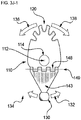
- FIGS. 1A and 1B show a typical forceps 10 of the prior art.
- FIG. 1A shows the forceps 10 in the closed position for clamping a tissue 34 between the opposing first clamp element 30 and second clamp element 31.
- FIG. 1B shows the forceps 10 in the open position, forcing tissue 34 apart.
- a first finger engager 20 and an opposing second finger engager 21 are used to actuate the mechanism.
- First finger engager 20 drives first clamp element 30, and second finger engager 21 drives second clamp element 31.
- a pivot 40 attaches the first clamp element 30 and the second clamp element 31, permitting a scissor-like action to force the first clamp element 30 and the second clamp element 31 together or apart, thereby clamping tissue 34 between the two clamp surfaces 35 and 36, or rending tissue 34 by the spreading of the first clamp element 30 and the second clamp element 31.
- a ratcheting clasp 50 is used to lock the first clamp element 30 and the second clamp element 31 together.
- FIG. 2 shows an example of an endoscopic forceps 60 of the prior art.
- a first finger engager 70 and an opposing second finger engager 71 are used to actuate the mechanism.
- First finger engager 70 is rigidly mounted to the instrument body 72.
- Second finger engager 71 drives opposing clamp elements 80 and 81.
- a pivot 90 attaches the two clamp elements 80 and 81, such that actuation of second finger engager 71 forces clamp elements 80 and 81 together, thereby clamping a tissue between two clamp surfaces 85 and 86.
- endoscopic forceps 10 can be used to force a tissue apart.
- Clamp elements 80 and 81 are closed, inserted into a tissue, and then opened to tear the tissue.
- a surgeon performs blunt dissection by closing the forceps, pushing the closed forceps into a tissue and then, optionally, opening the forceps inside the tissue, using the force applied by opening of the jaws of the forceps to tear the tissue apart. A surgeon thus proceeds to dissect a tissue by a combination of pushing into the tissue and opening the jaws of the forceps.
- Blunt dissection is commonly used for wet and slick tissues, and the smooth, passive surfaces of most surgical instruments slide easily along the tissue, impairing the instrument's ability to gain purchase and separate the tissue. Furthermore, the surgeon has only limited control, being able only to jab, move sideways, or separate. An improved instrument for blunt dissection that could differentially separate soft tissues while not disrupting firm tissues would greatly facilitate many surgeries.
- This disclosure includes methods and devices for blunt dissection, which differentially disrupt soft tissues while not disrupting firm tissues. According to a first aspect, there is provided a differential dissecting member as recited by Claim 1.
- DDA Differential Dissecting Attachments
- DDM Differential Dissecting Member
- soft tissue is defined as the various softer tissues separated, torn, removed, or otherwise typically disrupted during blunt dissection.
- Tiget tissue is defined as the tissue to be isolated and its integrity preserved during blunt dissection, such as a blood vessel, gall bladder, urethra, or nerve bundle.
- Firm tissue is defined as tissue that is mechanically stronger, usually including one or more layers of tightly packed collagen or other extracellular fibrous matrices. Examples of firm tissues include the walls of blood vessels, the sheaths of nerve fibers, fascia, tendons, ligaments, bladders, pericardium, and many others.
- a “complex tissue” is a tissue composed of both soft tissue and firm tissue and can contain a target tissue.
- a differential dissecting drive mechanism can grossly comprise first, an elongate member (which may be a housing) with a first, proximal end and a second, distal end, the first proximal end being associated with a mounting base suited to attaching to a surgical machine (for example a handheld laparoscopic instrument, or a surgical robot), second, a rotary drive train to generate rotation, third, a drive wheel to transmit that rotation, fourth, a motion filter to transform that rotation to oscillation, and finally a differential dissecting member to convert that oscillation into the dissection of complex tissues.
- the motion filter may further refine the rotational motion of the drive wheel into planar oscillation in one step, thereby greatly simplifying the design and manufacture of the differential dissecting attachment.
- FIGS. 3A through 3J-2 we disclose an alternate drive mechanism 100 for driving oscillation of a DDM.
- This drive mechanism 100 can be attached to a handle or to a surgical robot, or to another surgical machine.
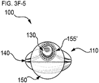
- FIG 3A discloses drive mechanism 100 housed within a cover 385, the drive mechanism 100 further comprising a rotary drive train 304 supplying rotary motion 390 about a central, longitudinal axis 398, with a distal end 396 of the rotary drive train 304 substantially pointed at a complex tissue (not shown) and a proximal end 397 of the rotary drive train 304 substantially pointed at, and associated with, a mounting base 375; a drive wheel 150 with its axis coincident to the central, longitudinal axis 398 of the rotary drive train 304, and located distally to drive train 304, the drive wheel's rotation 391 supplied by the rotary drive train 304, the drive wheel 150 further comprising a drive-point 155 located at a non-zero radius away from the longitudinal
- a differential dissecting member 110 is positioned distally from the drive wheel 150 with the differential dissecting member 110 being rotatable about an axis of member rotational oscillation 112 that is substantially transverse to the central, longitudinal axis 398 of the rotary drive train 304.
- the differential dissecting member 110 further comprises a wedge-like body 111, an axle 113 that can be substantially coincident and concentric with axis of member rotational oscillation 112, at least one tissue-engaging surface 120 located distalmost on the device 100 and substantially pointed at a complex tissue (not shown), a torque-point 130 disposed proximally to the substantially transverse axis of member rotational oscillation 112 of the differential dissecting member 110, the torque-point 130 being operably associated with the drive-point 155, such that the torque-point 130 travels rotatably around the central, longitudinal axis 398 with drive wheel rotation 391; a substantially flat motion filter 140 operably connecting the body 111 of the differential dissecting member 110 and the torque-point 130, the motion filter 140 transmitting from the drive-wheel 150 through drive-point 155 only a planar component output motion 392 of the rotary motion input 391 of the torque-point 130 to actuate the differential dissecting member 110 in planar rotary oscillation about its substantially transverse axis
- the drive-point 155 on the drive wheel 150 also rotates continuously, which continuously rotates the torque-point 130.
- the torque-point 130 is attached to the body 111 of differential dissecting member 110 by the motion filter 140, which in this arrangement is formed of an elastic planar member resisting in-plane deformation (and so transmits motion within that plane) but permits easy out-of-plane deformation (so not transmitting motion in that plane), which thus conveys only oscillatory planar motion 392 to the body 111 of differential dissecting member 110, which, thus oscillates about the substantially transverse axis of member rotational oscillation 112, causing the tissue engaging surface 120 to move in at least one direction 392 against the complex tissue, here in oscillatory planar motion 392, thereby this arrangement converts differential dissection member 110 oscillation into the dissection of complex tissues, disrupting at least one soft tissue in the complex tissue while avoiding disruption of firm tissue in the complex tissue.
- one complete rotation of the rotary drive train 304 drives two passes (one in the opposite direction to the other) along planar motion of the tissue engaging surface 120 of the differential dissecting member 110 against the complex tissue.
- a motor 310 operating (i.e., rotating) at 100 Hz thus drives the tissue engaging surface 120 past the tissue to be dissected at 200 passes per second.
- the drive wheel rotation 391 of the drive wheel 150 if the rotation 391 begins at position A, the tissue engaging surface 120 of the differential dissecting member 110 is mechanically constrained to point to position A'.
- the motion filter 140 here depicted as a planar leaf spring, easily deflects out of its own plane, and thus transmits to the differential dissecting member 110 only the planar component 392 (of drive wheel rotation 391) about the substantially transverse axis of member rotational oscillation 112, thus rotating the tissue engaging surface 120 to position B', in the same plane as position A'.
- the tissue engaging surface 120 of the differential dissecting member 110 is rotated to position C', continuing the planar motion 392.
- the tissue engaging surface 120 moves to point D' (identical to position B').
- the tissue engaging surface 120 of the differential dissecting member 110 also returns to position A', completing the cycle of oscillation of planar motion 392 of the differential dissecting member 110, and so the cycle of planar oscillation of the tissue engaging surface 120 against the complex tissue to be dissected.
- the rotary drive train 304 may further be comprised of a direct current brushed electric motor, a brushless electric motor, a pneumatic motor, or the like; the rotary drive train 304 may further comprise a gearhead 311, for changing the torque and rotational velocity of the motor 310, for example to reduce the speed of the rotary motion 391 in exchange for higher torque at the drive wheel 150 and so increased authority at the tissue engaging surface 120, permitting more powerful dissections if desired. If the arrangement is electric, power may be supplied by wires 399 to the motor 310.
- the motion filter 140 can be formed of an elastic sheet, for example a leaf spring composed of, for example, metal or a rigid polymer.
- the rotary drive train 304 is composed of at least one commercial-off-the-shelf, integrated, small-diameter electric motor 310 and gearhead 311, achieving a compact device.
- a motor-gearhead combination is the 4-millimeter-diameter, 26-millimeter-long EC4 brushless motor from Maxon USA.
- a differential dissecting attachment constructed with a rotary drive train employing this or a similar motor is thus compact enough for attaching to the end of most instruments regularly employed for minimally invasive surgery.
- the motion filter 140 can be formed of an elastic sheet, for example a leaf spring composed of, for example, metal or a rigid polymer.
- the material of the motion filter 140 may be distinct from that of the differential dissecting member 110, in which case it may be advantageous to provide a motion filter clamp 142 for holding the motion filter 140 therein.
- the substantially transverse axis of member rotational oscillation 112 might be comprised of a hole or cavity 114, for accepting an axle; if need be the hole 114 can be further fitted with a bushing or a roller bearing to reduce friction therebetween.
- FIGS. 3B through 3F-5 show several views of an oscillating differential dissecting member 110 with motion filter 140.
- the oscillating differential dissecting member 110 has a body 111 that is rotatably associated with a substantially transverse axis 112; the body 111 may possess a bearing cavity 114 to further accept an axle 113 a bushing or roller bearing 115 ( FIG. 3A and 4A ).
- the bearing cavity 114 may also be formed directly from the material of the wedge-like body 111 of the oscillating differential dissecting member 110, provided that a low-friction joint can be obtained between the body material and the material forming the axis 112; in FIG.
- the axis 112 is coincident with and defined by an axle 113.
- the tissue-engaging surface 120 is distal-most, as it dives into and safely dissects tissue.
- the tissue engaging surface 120 is the proximal-most portion of the oscillating differential dissecting member 110, namely the torque-point 130, which is operably associated with, and accepts rotational motion from, the drive wheel's 150 drive-point 155 (see FIG. 3A ).
- the torque-point 130 can take many forms to mate with and accept the rotary input delivered via the drive-point 155. In one arrangement (shown), the torque-point 130 takes the form of a truncated ball, while the drive-point 155 (see FIG. 3A ) can be a socket.
- the depicted arrangement features a motion filter clamp 142.
- the motion filter clamp 142 firmly grasps the distal-most end of the motion filter 140.
- the motion filter 140 can be any planar item that is flexible through its own plane, but resists shearing within its own plane.
- the motion filter 140 is formed out of spring steel.
- the differential dissecting member 110 oscillates in a sinusoidal fashion, as shown by arrows 136 and 138 in FIG. 3B .
- the oscillating differential dissecting member 110 with its associated motion filter 140 is stiff as a whole within the plane defined by the substantially flat motion filter 140.
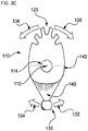
- FIG. 3C depicts a top view (shown by itself for clarity) of an oscillating differential dissecting member 110 with motion filter 140.
- the horizontal components 132 and 134 shown as 124 in the section view of FIG. 3F-0 ) of the rotary motion 391 of the torque-point 130, which are parallel to the plane of the page in this view, get transmitted via the motion filter clamp 142 to the body 111 of the oscillating differential dissecting member 110, driving the tissue engaging surface 120 as shown by arrows 136 and 138.
- the vertical component (element 126 in the section view of FIG. 3F-0 ) of the torque-point's 130 rotary motion that in this view passes through the plane of the page do not convey.
- the substantially flat motion filter 140 may be advantageous to manufacture as a triangular beam.
- the motion filter 140 is essentially an end-loaded, cantilevered beam; the triangular form ensures that the stresses are constant along the length of the beam, preventing damage due to stress concentrations while the drive mechanism 100 operates at hundreds of cycles per second, under varying loads during surgery. Also, the triangular form of the motion filter 140 concentrates its mass nearest the substantially transverse axis of member rotational oscillation 112, reducing the energy required to oscillate the differential dissecting member 110.
- FIG. 3D shows a side view of an arrangement of the oscillating differential dissecting member 110 with motion filter 140.
- the input motion (arrows 136 and 138 in FIGS. 3B and 3C ) of the oscillating differential dissecting member 110 in the depicted view ( FIG. 3D ) is now into and out of the plane of the page.
- the compliant bending of the torque-point 130 of the motion filter 140 along vertical component 126 is left-and-right as depicted in FIG. 3D .
- the shape of the motion filter clamp 142 is more clearly depicted in this view.
- the body 111 of the oscillating differential dissecting member 110 further forms a profile cam 144 impinging on the travel of the motion filter 140.
- the shape of the profile cam 144 serves to control the loading of the motion filter 140; as the spring steel in this arrangement bends, it conforms to the shape of the motion filter profile cam 144.
- the shape of the profile cam 144 is arbitrary and can serve to preload the spring steel of the motion filter 140 to prevent backlash and keep the motion of the drive mechanism 100 smooth.
- FIG. 3E shows an end view of an oscillating differential dissecting member 110 with motion filter 140. The rotary travel of the torque-point 130 lies substantially in the plane of the page, as is more clearly shown in FIGS. 3F-1 through 3F-4 .
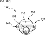
- FIG. 3F-0 depicts in section view looking distally the components of the rotary motion 391 (see also FIG. 3A ) of the drive wheel 150 and drive-point 155 in relation to the differential dissecting member 110 and motion filter 140.
- the rotational motion 391 of the drive wheel 150 is comprised of two components: a vertical component 126, and a horizontal component 124.
- the motion filter 140 being an elastic flat plate, for example a steel leaf spring, bends easily out of its plane, easily accommodating the vertical component 126 of the rotary motion 391; since the substantially transverse axis of member rotational oscillation 112 (see FIG. 3A ) resists the vertical component 126, no motion about axis 112 can occur.
- the motion filter 140 is an elastic flat plate possessing substantial rigidity within its own plane, and, since the substantially transverse axis of member rotational oscillation 112 expressly permits easy rotational motion in that same plane, all of (and only) the horizontal component 124 of the rotational motion 391 is transmitted from the rotary drive train 304 (see FIG. 3A ) to the differential dissecting member 110, thus inducing oscillations in that plane, and so sweeping the tissue engaging surface 120 (see FIG. 3A ) bi-directionally (parallel to the horizontal component 124) across the complex tissue to be dissected.
- FIGS. 3F-1 through 3F-4 further depict in cross-section view through the drive wheel 150 the sequential (here, counterclockwise) motion of this portion of the rotary drive train 304 (see FIG. 3A ).
- the drive wheel 150 drives the drive-point 155 which engages and so drives the torque-point 130, itself driving the motion filter 140 of the oscillating differential dissecting member 110.
- the drive wheel 150 is rotated so that the drive-point 155 is to the viewer's left (at the 9 o'clock position).
- the torque-point 130 being engaged to the drive-point 155, has followed the drive-point 155, forcing the motion filter 140 to the left, which in turn forces the differential dissecting member 110 to rotate about the axis of member rotational oscillation 112 (see FIG. 3A ). This necessarily forces the distal tissue engaging surface 120 (not visible in this view; it is at the opposite end of the differential dissecting member 110) to the right.
- FIG. 3F-2 the drive wheel 150 has rotated counterclockwise so that the torque-point 130 is at the bottom of travel (the 6 o'clock position); while the entire oscillating differential dissecting member 110 has returned to center. Note the downward-bent state of the motion filter 140, which has filtered out the (in this view) vertical component 126 (see FIGS. 3C and 3D ) of the rotational motion 391 of the torque-point 130.
- the drive wheel 150 (and so the drive-point 155, and the torque-point 130) has cycled counterclockwise around to the viewer's right (the 3 o'clock position), driving the tissue engaging surface 120 to the viewer's left.
- FIG. 3F-3 the drive wheel 150 (and so the drive-point 155, and the torque-point 130) has cycled counterclockwise around to the viewer's right (the 3 o'clock position), driving the tissue engaging surface 120 to the viewer's left.
- 3F-4 continues the cycle, with the drive-point 155, and the torque-point 130 rotating counterclockwise to the viewer's 'up' position (12 o'clock). Continuing rotational motion 391 clockwise will bring the drive wheel 150 and so the drive-point 155 and so the torque-point 130 to the nine-o'clock position, completing the cycle.
- the continuous rotation 391 of the drive wheel 150 that drives the non-rotating torque-point 130 means that frictional losses at the drive-point 155 could cut the efficiency of the drive mechanism 100.
- 3F-5 shows an arrangement of a drive mechanism 100 wherein a drive wheel 150 operably connects to a torque-point 130 via a drive-point 155' formed by a roller bearing, greatly reducing frictional losses due to relative rotation between the drive wheel 150 and the torque-point 130.
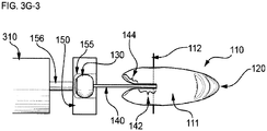
- FIGS. 3G-1 through 3G-4 we see the same process from a side view; the sequential motion of the oscillating differential dissecting member 110 oscillates due to its engaging the drive train 304 (shown partially here, and fully in FIG. 3A ) via the motion filter 140.
- the torque-point 130 here depicted as a truncated ball, tilts significantly within the drive-point 155, here depicted as a socket.
- FIG. 3G-1 (a side view of the device shown in FIG.
- a motor 310 has, via driveshaft 156, rotated the drive wheel 150 so that the drive-point 155 is farthest from viewer.
- the torque-point 130 being engaged to the drive-point 155, has necessarily followed the drive-point 155, forcing the motion filter 140 (in this arrangement, a leaf spring) to rotate away from the viewer, thus forcing the differential dissecting member 110 to rotate about the axis of member rotational oscillation 112 and so necessarily forcing the distal tissue engaging surface 120 toward the viewer.
- the elastic, plate-like motion filter 140 is unbent; we can also see the motion filter clamp 140 formed in the body 111 (see FIG. 3A ) of the differential dissecting member 110 and holding the motion filter 140. At this point, the profile cam 144 is not engaged.
- FIG. 3G-2 we see the side view of the stage depicted in FIG. 3F-2 where the motor 310 has caused (via driveshaft 156) the drive wheel 150 to rotate counterclockwise so that the torque-point 130 is now at the bottom of its rotational motion 391 (see FIG. 3A ).
- the oscillating differential dissecting member 110 has returned to center, and at this moment the tissue engaging surface 120 points directly distally, in this view, to the viewer's right (equivalent to position B' and D' in FIG. 3A ).
- the downward-bent state of the elastic, plate-like motion filter 140 which has filtered out the (in this view) vertical component 126 (see FIG. 3F-0 ) of the rotational motion 391 (see FIG.
- FIG. 3G-3 a side view of the part of the oscillation cycle depicted in FIG. 3F-3
- the motor 310 has rotated, counterclockwise, via shaft 156, the drive wheel 150 (and so the drive-point 155, and so the torque-point 130) toward the viewer.
- the motion filter 140 is unbent.
- the motion filter 140 has cycled counterclockwise around away from the viewer, driving the tissue engaging surface 120 away from the viewer.
- the motion filter clamp 142 formed in the body 111 of the differential dissecting member 110 and securely holding the motion filter 140, and, we can see that the profile cam 144 is not engaged.
- FIG. 3G-4 complimenting FIG. 3F-4 above, we see now the complete cycle, with the drive-point 155, and the torque-point 130 rotating counterclockwise to the viewer's 'up' position.
- the motion filter 140 is clearly bent upward along vertical component 126 (which, due to the motion filter 140, contributes nothing to the oscillatory motion of the differential dissecting member 110). It can be seen that the bending of the motion filter 140 causes the torque-point 130 to rotate within the plane of the page in FIGS. 3G-1 through FIG. 3G-4 . For this reason, we show that a preferred form of the torque-point 130 can be a sphere, ball, or portion thereof.
- the arrangements shown can be run at high speeds; the continuous rotational motion 391 of the drive wheel 150 that drives the non-rotating torque-point 130 means, along with the tilting ball disclosed above, that frictional losses at the drive-point 155 could cut the efficiency of the drive mechanism 100.
- employing a spherical torque-point 130 captured in a roller bearing (for example as depicted in FIG. 3F-5 ) serving as the drive-point 155 may reduce these losses to a minimum.
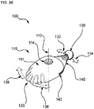
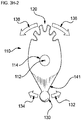
- FIG. 3H-1 shows an oblique view of an alternative arrangement of oscillating differential dissecting member 110 with an integral motion filter 141.
- the body 111 of the oscillating DDM 110 is molded to integrally include a flat elastic plane that serves as an integral motion filter 141, making the entire oscillating differential dissecting member 110 monolithic, which may possibly simplify manufacture.
- FIGS. 3H-2 , 3H-3 , and 3H-4 depict a top view, a side view, and an end view, respectively, of the alternative arrangement of an oscillating differential dissecting member 110 with an integral motion filter 141.
- This arrangement can be molded out a single material (for example PEEK (pollyetheretherketone)), as long as the elastic modulus is high enough to prevent buckling out-of-plane during transmission of the in-plane horizontal component 124 of the rotary motion 391 while filtering out the out-of-plane, vertical component 126 of the supplied rotary motion 391.
- the features of the integrally molded motion filter 141 are similar to that depicted in FIGS. 3B through 3E , save for the reduced complexity and time involved in producing the part for incorporation into a drive mechanism 100.
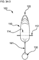
- FIGS. 3J-1 and 3J-2 depict top and side views of another arrangement of an oscillating differential dissecting member 110 rotatable about substantially transverse axis of member rotational oscillation 112, further comprising a bearing cavity 114, and provided with an alternative motion filter 143 comprised of a rigid flat plate 143 attached to the differential dissecting member 110 via a hinge 149.
- This arrangement requires no elastic plates or gripping of same; a hinge is a well-understood mechanical feature.
- the operation of this motion filter 143 is much as was disclosed above, where the torque-point 130 engages the drive-point 155 of the drive wheel 150 driven in rotational motion 391 by the rotary drive train 304 (see FIGS.
- This hinged motion filter 143 transmits the horizontal component 124 of rotational motion 391 without the vertical component 126.
- its operation is similar to those disclosed in FIGS. 3B to 3E , and 3H-1 to 3H-4 ), where motion of the torque-point 130 in the direction of arrow 132 drives the tissue engaging surface 120 in the direction of arrow 136, and motion of the torque-point 130 along arrow 134 results in the sweep of the tissue engaging surface 120 in the direction of arrow 138.
- a hinge spring 148 is easily added to achieve some of the benefits disclosed above.
- a highly elongate compact drive train 400 enabling differential dissection in tight confines.
- Modern minimally invasive surgery has reduced the diameter (and burgeoning obesity has increased the length) of the surgical instruments required, demanding elongate, narrow, specialized tools for laparoscopic, endoscopic, thoracoscopic, and robotic procedures inserted through access ports, trocars and natural orifices.
- the inner diameters of trocars it is commonplace for the inner diameters of trocars to be as small as 8, 5, and even 3 millimeters. It can be challenging to provide sufficient torque in instrument shafts of these diameters using one of even the best available motors.
- a compact rotary drive train comprised of a plurality of small electric motors with driveshafts emerging from both ends, laid end-to-end coaxially in a column, sharing a common axis, and further comprising couplings associating the distal end of one motor driveshaft with the proximal end of another, adjacent motor driveshaft, forming a mechanical series.
- the torque output of such a mechanical series motor arrangement is proportional to the number of motors in the column. In this way any required torque can be added to a very narrow surgical instrument.
- This mechanical series motor can further be provided within a narrow diameter, elongate rigid steel tube, as is the norm for other minimally invasive surgical instruments. Disclosed herein is how these can form articulated instrument shafts well-suited to the contortions of minimally invasive surgery.
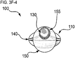
- FIG. 4A shows an oblique view of the components of a highly elongate compact drive train 400 comprising the distal portion of a differential dissecting instrument for attaching to a handle or to a surgical robot.
- the highly elongate compact drive train 400 is not dissimilar in part to the device depicted in FIG. 3A , save for the distinguishing features disclosed below.
- the highly elongate compact drive train 400 comprises a longitudinal axis 398 having a first, proximal end 397 that may be associated with a mounting base 375 facilitating attachment to a handheld surgical instrument or surgical robot, and a second, distal end 396 directed at a complex tissue to be dissected, and associated with an oscillating differential dissecting member 110.
- the two ends of the highly elongate compact drive train 400 are connected on the outside by a housing 385 (shown transparent for clarity), and largely occupied on the inside by a multiple-motor rotary drive train 305, and an oscillatory drive mechanism 303 nearer the distal end 396.
- the multiple-motor rotary drive train 305 is comprised of a plurality of double-shafted motors 310 (where each motor 310 is affixed to the housing 385, and each motor 310 further possesses a drive shaft 314 emerging from both ends of motor 310).
- each adjacent motor 310's drive shafts 314 are coaxially connected and rotationally locked to one another by torsionally stiff, flexible joints 313, so that the entire multiple-motor rotary drive train is connected in mechanical series. Further the drive shafts all rotate as one unit, with every motor 310 rotationally phase-locked to the others, such that all motors rotate at the same speed in the same direction 360.
- the differential dissecting member 110 possesses a body 111 and is located rotatably about a substantially transverse axis of member rotational oscillation 112 (which may be comprised of an axle 113) at the distal end 396 of the highly elongate compact drive train 400.
- the differential dissecting member 110 also connects operably to the oscillatory drive mechanism 303.
- the oscillatory drive mechanism 303 is itself comprised of (beginning proximally) a drive wheel 150 operatively associated with, and rotated by, the distal-most end 396 of the multiple-motor rotary drive train 305, the drive wheel further comprising a drive-point 155 located at a non-zero radius from the longitudinal axis 398 (which is also the axis of drive wheel 150 rotation).
- the drive-point 155 engages, captures and drives in rotation 391 about long axis 398 a torque-point 130, which in this arrangement forms the proximal-most extent of a motion filter 140.
- the motion filter 140 is fixed to the body 111 of the differential dissecting member 110 by a motion filter clamp 142.
- the differential dissecting member 110 possesses at least one tissue-engaging surface 120 (directed at a complex tissue to be dissected).
- the entirety of the series of motors 310 are appropriately connected by power cables 399 according to the type of motor used, and providing the power for dissecting complex tissue.
- the arrangement depicted also includes a gear head 311 operatively associated with the distal end 396 of the multiple-motor rotary drive train 305 and rotated by it, and the proximal-most portion of the oscillatory drive mechanism 303. This allows the multiple-motor rotary drive train 305 to run at high rotational frequencies while the oscillatory drive mechanism 303 can cycle at lower rotational frequencies, with enhanced torque 390 (and so, enhanced authority of the device during forceful blunt dissection).
- rotation of the multiple-motor rotary drive train 305 drives rotation of the oscillatory drive mechanism 303, which imparts rotational motion 391 to the drive wheel 150, which in turn rotates the drive-point 155.
- the drive-point 155 captures and so also rotates the torque-point 130 comprising the proximal-most portion of the motion filter 140.
- the motion filter 140 transmits only the co-planar component, i.e., the horizontal component 124 of the rotary motion 391 of the torque-point 130 to the body 111 of the differential dissecting member 110.
- the tissue engaging surface 120 of the differential dissecting member 110 will point at position A'.
- the motion filter 140 bends out of its own plane and transmits to the differential dissecting member 110 only the horizontal component 124 of drive wheel rotation 391.
- the differential dissecting member 110 thus forces the tissue engaging surface 120 to point at position B', on center and pointing directly distally, aligned with the longitudinal axis 398.
- the tissue engaging surface 120 of the differential dissecting member 110 sweeps on to point at position C', continuing the planar motion 392.
- the tissue engaging surface 120 now moves to point D' (identical to position B', and aligned again with the longitudinal axis 398 of the highly elongate compact drive train 400).
- the tissue engaging surface 120 of the differential dissecting member 110 also returns to position A', completing the cycle of oscillation of planar motion 392 of the differential dissecting member 110.
- the cycle of bi-directional, planar oscillation of the tissue engaging surface 120 against the complex tissue to be dissected proceeds, disrupting at least one soft tissue in the complex tissue while avoiding disruption of firm tissue in the complex tissue.
- the highly elongate compact drive train 400 converts electrical power input into the safe and rapid dissection of complex tissues by otherwise unwieldy laparoscopic instruments or surgical robotic arms, to enable improved surgical outcomes.
- FIG. 4B shown in FIG. 4B is a side view of an exposed multiple-motor rotary drive train 308 formed by a coaxial plurality of rotating motors 310, focusing in this view especially on the arrangement of two adjacent motors 310 and 310' with their adjacent driveshafts 314 and 314' connected by a reasonably torsionally stiff, flexible joint 313 (for example, made of an elastomeric tube, block, or rod, which tend to be quiet under way).
- very inexpensive motors such as mass-produced DC brushed motors from manufacturers like Mabuchi Motors
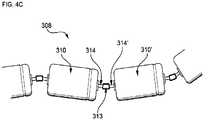
- FIG. 4C shows a side view of the same actively rotating multiple-motor rotary drive train 308 disclosed above in FIG. 4B , but in this view, the plurality of motors 310 have been purposely deflected out of a straight alignment, though the motors are still coaxial at the joints 313 where the driveshafts 314 touch.
- the driveshafts 314 and 314' of motors 310 and 310' still connected by the torsionally stiff, flexible joint 313, we can see how this arrangement permits reasonable deflections (and misalignments) of the multiple-motor rotary drive train 305 from a straight line while still actively delivering torque downstream, for example to an oscillatory drive mechanism 303.
- the motors are prevented from relative rotations relative to one another, all of the motors in such an arrangement will remain rotationally phase-locked, turning together as one multiple-motor rotary drive train 305 (see FIG. 3A ).
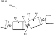
- FIG. 4D shows a side view of a somewhat similar multiple-motor rotary drive train 306.
- the plurality of motors 310 have their driveshafts 314 connected by universal joints 315, showing deflections from a straight line while delivering torque as one unit, similar to the situation depicted in FIG. 4C .
- Universal joints 315 are typically much more torsionally rigid than the elastomeric joints 313 shown in FIGS. 4B and 4C ; the disclosed arrangements may usefully employ either.
- Other means to transmit torsion while bending are known in the art, including but not limited to sliding dog-bone joints, interlaced spider joints, bellows joints, and the like.
- universal joints 315 in multiple-motor rotary drive train 306 are that the energetic losses of deforming the material out of which are constructed the flexible joints in multiple-motor rotary drive train 308 above are that the universal joints 315 can be constructed with low-friction steel bearings. Further advantages of universal joints 315 is that the degree of permitted deflection may be larger than for flexible elastomeric joints 313, and that they usually withstand greater torque.
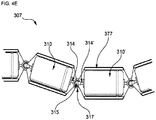
- FIG. 4E shows a cross-sectional side view of an arrangement of a similar multiple-motor rotary drive train 307 to that disclosed in FIG. 4D , here comprising a plurality of motors 310 each with their driveshafts 314 connected to adjacent drive shafts by drive shaft universal joints 315.
- Each motor 310 in this arrangement is further covered by its own associated housing segment 377 within which each motor 310 is fixed.
- Each housing segment 377 is also articulated at either end by a housing joint 317, surrounding the associated drive shaft universal joints 315 and thereby connecting each housing segment 377 to adjacent housing segments 377 and each drive shaft 314 to adjacent drive shafts 314.
- this arrangement of a multiple-motor rotary drive train 307 can deflect out of alignment as can the similar arrangements above, save that each motor 310 is fixed within its associated housing segment 377, providing structure to fight the reaction torque produced when the motor 310 energizes and rotates its drive shaft 314. So, as the multiple-motor rotary drive train 307 bends in one plane as depicted, the constituent motors 310 provide a combined maximum torque due to the stability provided by the housing segments 377. Further, the housing segments 377 provide a convenient surface to attach to a surgical robot or laparoscopic instrument, thus serving as an alternative mounting base 375 (see FIG. 3A and 4A ).
- FIG. 4F-1 and 4F-2 depict a multiple-motor rotary drive train 407 (and a component of same) with a plurality of motors 410 similar to those in FIG. 4E , each covered and supported by its own housing segment 477 and connected to each other by multiplanar concentric universal joints 418.
- the multiple-motor rotary drive train 407 is here shown deflecting in two planes at once, demonstrating three-dimensional flexibility appropriate for negotiating the twists and turns inside a patient.
- a multiplanar concentric universal joint 419 combining a universal joint 415 that is connecting adjacent drive shafts 414 of adjacent motors 410, and, a similar two-axis housing segment joint 417.
- a universal joint is typically comprised of two axles oriented at right angles to one another, crossing at a geometric center, and both axles are typically oriented at right angles to the drive shafts with which they are associated, and, the axis of rotation of the associated drive shafts are aligned with that same geometric center. This is the case with the drive shaft universal joint 415.
- the housing segment joint 417 of this arrangement 407 is similarly comprised of two axes (defined by axles) 420 and 421, oriented at right angles to both one another and to the axis of rotation of the drive shafts 414, all crossing at a geometric center of rotation 419.
- the universal joint 415 and housing segment joint 417 are arranged with common geometric centers of rotation. This means that the drive shafts 415 of the motors 410 are free to deflect while delivering torque despite being affixed in, and surrounded by, articulated rigid housing segments 477.
- each drive shaft universal joint 415 and associated housing segment joint 417 share a single geometric center of rotation 419 in all planes.
- FIG. 4F-1 depicted in this figure are at least one housing segment joint 417, each comprising a ring supporting a vertically oriented pin joint 421 permitting rotation substantially in and out of the plane of the page, and a horizontally oriented pin joint 420, permitting rotation substantially within the plane of the page.
- the axes of the vertically oriented pin joint 421 and the horizontally oriented pin joint 420 cross exactly at a single geometric center of rotation 419 in all planes, the same geometric center of rotation 419 that is also used by the drive shaft universal joint 415.
- FIG. 4F-2 shows in schematic form one housing segment joint 417 of a multiple-motor rotary drive train 407, a single center of rotation 419, and how it is formed by the convergence of the axes of the vertically oriented pin joint 421, the horizontally oriented pin joint 420, and the universal joint 415.
- this arrangement permits the free deflection of the motors 410 whilst they are fixed within their housing segments 477, and simultaneously preserving phase-locked rotation of the entire multiple-motor rotary drive train 407.
- FIG. 4G shows an oblique view of a multiple-motor rotary drive train 409 comprised of a plurality of coaxial motors 410 with their driveshafts 414 connected to one another and phase-locked by universal joints 416. Further, this arrangement 409 further comprises a flexible compliant sheath 444 (here shown in transparent form) covering the plurality of motors 410. The compliant sheath 444 is alternative to the rigid housing segments 477 from earlier arrangements.
- the compliant sheath 444 permits all manner of deflections, including some rotational deflections of the motors 410, it still limits those rotational deflections, allowing the motors 410 to develop and deliver useful torque to supply downstream, for example to an oscillatory drive mechanism 303 (see FIG. 3A and 4A ).
- This view shows deflections from a straight line of motors 410 in two planes at once, and also rotational deflections of individual motors 410, all while phase-locked as before and delivering torque. Such an arrangement as this can be useful.
- a soft cover like the compliant sheath 444 may be preferable in some minimally invasive surgeries.
- the compliant sheath 444 and the housing segments 477 might also be fruitfully combined in irregular fashion, where neither motor cover scheme dominates the entire length of the multiple-motor rotary drive train 409.
- FIGS. 5A through 5E-3 disclosed are for surgical machines such as handheld laparoscopic instruments or surgical robots, arrangements of differential dissecting instruments and components for same that can perform blunt dissection of complex tissues in any desired direction. That is, the surgeon can steer the path of differential dissection at will, even remotely from the point of access (for example an incision, port, or a natural orifice), safely creating tunnels, pockets, and throughways of any desired shape in, around, or through complex tissues.
- steerable differential dissectors for differential dissection of complex tissues in any desired direction operated remotely or directly.
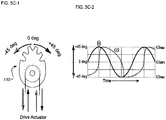
- FIG. 5A-1 depicts one arrangement (and basic operation) of a steerable differential dissecting assembly 500 enabling differential dissection in any desired direction. Also disclosed is a steerable differential dissecting assembly 500, comprising a differential dissecting member 110 oscillatible about a substantially transverse axis of member rotational oscillation 112, a drive means 160 for driving the differential dissecting member 110 in oscillations about substantially transverse axis of member rotational oscillation 112, and a tissue engaging surface 120 forming the distal-most portion of the steerable differential dissecting assembly 500.
- the differential dissecting member 110 has an amplitude of oscillation 538 of the differential dissecting member 110, a magnitude of travel 536 of the drive means 160, a leftward swing 537' of the differential dissecting member 110, a leftward-driving input 537 driving the leftward swing 537', a rightward swing 539' of the differential dissecting member 110, a rightward-driving input 539 driving the rightward swing 539', a center of oscillation 538' of the differential dissecting member 110 that is substantially halfway between the leftward swing 537' and the rightward swing 539', and a direction of dissection 121 substantially aligned with the a center of oscillation 538' of the differential dissecting member 110.
- the steerable differential dissecting assembly 500 oscillates the differential dissecting member 110 via the a drive means 160, which can be a cable drive 160 as in FIG. 6A-1 , or a oscillatory drive train as shown in FIG. 3A and 4A .
- the amplitude of oscillation 538 of the differential dissecting member 110 is controlled by the magnitude of travel 536 of the drive means 160, and the leftward-driving input 537 and the rightward-driving input 539 control the left and right swings 537' and 539', respectively.
- the differential dissecting member 110 typically oscillates left and right to either side of the center of oscillation 538 about a substantially transverse axis of member rotational oscillation 112, driven by a cable loop 160, and presenting a tissue engaging surface 120 distally to the complex tissues to be dissected.
- the direction of rotation of the differential dissecting member 110 about the substantially transverse axis of member rotational oscillation 112 depends on the balance of tension applied to the ends of cable loop 160.
- the authority i.e., the surplus of force of the tissue engaging surface, relative to the force required to dissect the tissue
- the amplitude of the oscillation 538 about the center of oscillation 538' depends on the magnitude of travel 536 through which the cable loop 160 travels.
- the overall motion of the differential dissecting member 110 is thus a function of the motion of the cable loop 160, such that a leftward-driving input 537 (half-shaded bold arrows) results in a leftward swing 537' of the differential dissecting member 110, while a rightward-driving input 539 (solid black bold arrows) results in a rightward swing 539' of the differential dissecting member 110.
- the differential dissecting member 110 is depicted oscillating in a steady, symmetrical, sinusoidal fashion 45 degrees to either side of a center of oscillation 538' that points exactly distal, coincident with the longitudinal axis 398 of the differential dissecting instrument and directed toward the tissue to be dissected.
- the direction of dissection 121 in this case point forward, in that the complex tissue is dissected directly in front of the differential dissecting attachment.
- FIG. 5A-2 Disclosed in FIG. 5A-2 is a schematic of the regular sinusoidal motion of the differential dissecting member 110 in FIG. 5A-1 .
- Time 570 forms the x-axis
- the y-axis is shown on the left-hand side as theta [ ⁇ ]
- angular position 572 of the differential dissecting member 110 in degrees away from the center of oscillation 538'
- omega [ ⁇ ] omega [ ⁇ ]
- the rotational velocity 574 of the differential dissecting member 110 drops to zero as its angular position 572 reaches the extreme of 45 degrees, and the rotational velocity 574 of the differential dissecting member 110 reaches its maximum when the angular position 572 crosses zero degrees.
- This example of motion of the differential dissecting member 110 that is, regular sinusoidal oscillation about a center of oscillation 538' that is coincident with the longitudinal axis 398 of the differential dissecting attachment 100, so that the direction of dissection 121 is exactly distal, can be considered typical state of a differential dissecting attachment. That said, it is by no means a limiting case, as there is much to be gained by dynamically varying the rotational velocity 574, the angular position 572, or both.
- oscillation about the center of oscillation 538' drives dissection up and to the left.
- the direction of dissection 121 can be changed at will by controlling the motion of the drive means 160, which in this arrangement is the cable loop 160.
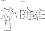
- FIGS. 5B-1 and 5B-2 depict a cable-driven, controllable differential dissecting member 110 oscillating in a steady, symmetrical, sinusoidal fashion about an offset center of oscillation 538' that points at a non-zero angle (here, 22.5 degrees to the viewer's left) from the longitudinal axis of the differential dissecting instrument.
- the direction of dissection 121 thus points to the left, and, as the differential dissecting member 110 oscillates about that leftward-leaning offset center of oscillation 538', and so the direction of dissection 121.
- tissue to be dissected gives way preferentially on the left, and the resistance of dissection decreases on the left, and the steerable differential dissecting assembly 500 tunnels to the left.
- the steerable differential dissecting assembly 500 can be directed to tunnel in any desired direction by controlling the offset.
- FIGS. 5C-1 and 5C-2 depict a cable-driven, controllable differential dissecting member oscillating in a symmetrical fashion, but with a varying angular velocity profile, about a center of oscillation 538' that points exactly forward about the longitudinal axis 398 of the differential dissecting instrument.
- the varying angular velocity profile generates off-axis forces against the tissue to be dissected, thus driving the direction of dissection 121 off-axis, and the steerable differential dissecting assembly 500 dissects preferentially in that direction.
- FIGS. 5C-1 and 5C-2 depict a cable-driven, controllable differential dissecting member oscillating in a symmetrical fashion, but with a varying angular velocity profile, about a center of oscillation 538' that points exactly forward about the longitudinal axis 398 of the differential dissecting instrument.
- the varying angular velocity profile generates off-axis forces against the tissue to be dissected, thus driving the direction of dissection 121
- 5D-1 and 5D-2 depict a cable-driven, controllable differential dissecting member 110 oscillating in a steady, symmetrical, sinusoidal fashion, but with a varying angular velocity profile, about a center of oscillation 538' that points at a non-zero angle from the longitudinal axis 398 of the differential dissecting instrument.
- the combination also generates asymmetrical dissection, driving a change in the direction of dissection 121, allowing the steerable differential dissecting assembly 500 to dissect in a direction chosen by the surgeon.
- FIGS. 5E-1 through 5E-3 show a controllable differential dissecting dissector 500 located at the distal end of an endoscope, oscillating about a center of oscillation 501, creating a direction of dissection, and dissection in that direction, and showing arbitrary control of the direction of dissection thus permitting tunneling in arbitrary directions within complex tissues.
- FIG. 5E-1 through 5E-3 show a controllable differential dissecting dissector 500 located at the distal end of an endoscope, oscillating about a center of oscillation 501, creating a direction of dissection, and dissection in that direction, and showing arbitrary control of the direction of dissection thus permitting tunneling in arbitrary directions within complex tissues.
- 5E-1 shows the steerable differential dissecting assembly 500, comprising a differential dissecting member 510 fixed to oscillate on the distal-most portion 511 of a flexible instrument shaft 555, the oscillation possessing a center of oscillation 501, a first extent of oscillation 502 and a second extent of oscillation 503, and an amplitude of oscillation 514 defined by the angle between the first extent of oscillation 502 and a second extent of oscillation 503.
- the steerable differential dissecting assembly 500 further comprises a longitudinal axis 518 and a direction of dissection 516.
- the differential dissecting member 510 is not unlike the others disclosed in this document, possessing a tissue engaging surface, a substantially transverse axis of member rotational oscillation, and the like.
- the direction of dissection 516 is defined as the center of the narrow region of tissue that experiences a sufficient differential dissection effect so that a complex tissue there differentiates into preserved firm or organized tissue and disrupted soft, less-well organized tissue.
- the direction of dissection 516 is coincident with the center of oscillation 501.
- the differential dissecting member 510 oscillates, it typically oscillates sinusoidally about a center, usually halfway between the first extent of oscillation 502 and a second extent of oscillation 503; we define that halfway point as the center of oscillation 501.
- the oscillations of a differential dissecting member 510 are determined in a cable-driven device as disclosed in FIG. 3A and 5A-1 to 5D-2 by the magnitude of the change in tension (and so, position) over time; a oscillatory drive train as disclosed in FIGS. 3A , 4A can vary motor speed.
- the direction of dissection 121 (or 516) is controllable at the discretion of the surgeon.
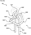
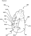
- FIGS. 6A-1 through 6B-5 to ensure improved performance and safety for a differential dissecting instrument, we disclose below, and first in FIG. 6A-1 , an embodiment 600 of a differential dissecting member 110.
- This differential dissecting member 110 is captured by, and driven to oscillate by, a continuous, circuitous loop 160 of fine wire rope or cable passing through a series of fenestrations (passages) through the body 111 of the differential dissecting member 110 and proximally away to a drive mechanism.
- the continuous, circuitous loop 160 is made up of portions 160A-160G of a fine wire rope or cable.
- the circuitous route of the loop through and around the body 111 of the differential dissecting member 110 forms a "lark's head” or “cow-hitch” knot, a topologically constrained path that captures the differential dissecting member 110, preventing its loss. This path is also referred to as a "tortuous" path.
- the differential dissecting member 110 has a longitudinal axis 398 with a first, proximal end 397 substantially directed toward a drive mechanism on, within, or associated with a handle or surgical robot, and a second, distal end 396, substantially directed distally toward a tissue to be dissected.
- the differential dissecting member 110 is rotatable about a substantially transverse axis of member rotational oscillation 112 which is perpendicular to the longitudinal axis 398 and located near the longitudinal axis 398's second, distal end 396.
- the differential dissecting member 110 further has a roughly wedge-like body 111, which is substantially aligned with the longitudinal axis 398, and a tissue-engaging surface 120 substantially directed distally toward the tissue to be dissected and forming the somewhat thinner tip of the wedge-like body.
- the body further possesses a first face side 691 of the wedge-like body 111 and a second, back side 692 of the wedge-like body 111.
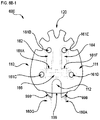
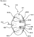
- the body 111 of the differential dissecting member 110 further comprises a series of short, shallow surface troughs and through-body-holes (passages) which are adapted to accept, capture, and allow passage of a continuous loop of fine wire rope or cable that holds the differential dissecting member 110 to the rest of the surgical instrument.
- the first, face side 691 has a mouth-like trough 166 and two eye-like troughs 162 and 164.
- the second, back side 692 has two ear-like troughs 162' and 164'.
- the mouth-like trough 166 further comprises two passages 161C and 161D which pass completely through the body 111 of the differential dissecting member 110.
- the eye-like trough 162 has a passage 161B passing through to the second, back side of the differential dissecting member 110, and a longitudinally-oriented passage 161A that travels out the bottom of the differential dissecting member 110.
- the eye-like trough 164 has a passage 161E passing through to the second, back side of the differential dissecting member 110, and a longitudinally-oriented passage 161F that travels out the bottom of the differential dissecting member 110. Viewing also FIGS.
- 6B-1 (a direct view of the first, face side 691 of the differential dissecting member 110) and 6B-2 (a direct view of the second, back side 692 of the differential dissecting member 110), we see that there on the second, back side 692 are two more troughs: ear-like trough 164', further comprising the passage 161E and the passage 161D, and ear-like trough 162', further comprising the passage 161B and the passage 161C.
- FIGS. 6A-1 , 6B-1 , and 6B-2 review now the circuitous path of the cable loop 160 depicted clearly in FIG. 6A-2 .
- the cable loop section 160A first passes up distally through passage 161F into the bottom of the eye-like trough 164 in the first, face side 691 of differential dissecting member 110.
- the cable loop 160 then travels from there up distally through the eye-like trough 164 as loop section 160B and passes from the first, face side 691 through passage 161E, emerging as loop section 160B' into the ear-like trough 164' on the second, back side 692 of the differential dissecting member 110.
- the cable loop 160 then turns and travels proximally down through that trough 164', and, as loop section 160C', passes through passage 161D, emerging as loop section 160C into the mouth-like trough 166 in the first, face side of differential dissecting member 110.
- the loop then passes as loop section 166D in the mouth-like trough 166, traversing the face of the first, face side 691.
- the inventors of the subject matter disclosed in this application have found it advantageous to further design the mouth-like trough 166 to "bite" or "pinch” the cable loop 160.
- This feature is most clearly observed in FIG. 6B-5 , the profile view of the embodiment 600 of the differential dissecting member 110.
- the differential dissecting member 110 can thus pinch the fine cable or wire loop 160, securing it cleat-like in the mouth-like trough 166 where the stresses that would tend to dislodge it are the lowest.
- the body 111 of the differential dissecting member 110 further comprises stabilizers 999, that help secure the differential dissecting member 110 onto an axle whose axis is coincident with the substantially transverse axis of member rotational oscillation 112, the stabilizers 999 further possessing a shape allowing clearance for the cable loop section 160A.
- the path of the circuitous loop can be traced substantially symmetrically through the remaining passages.
- the cable loop 160 completes its traverse of the first, face side 691 in the mouth-like trough 166, then passing as loop section 160E away from the first, face side 691 through passage 161C to emerge on the second, back side 692 as loop section 161E' into the proximal-most end of ear-like trough 162'.
- this embodiment 600 of a differential dissecting member 110 further includes developing opposed tensile forces 137 and 139 on the cable loop sections 160G and 160A, respectively. Note further that when tensile force 137 is greater than tensile force 139, so that an imbalance is present. This force imbalance drives the differential dissecting member 110 to rotate about the substantially transverse axis of member rotational oscillation 112 in the direction of arrow 136. Conversely, if the tensile force 139 becomes greater than the tensile force 137, then the differential dissecting member 110 rotates about axis 112 in the direction of arrow 138.
- the tensile forces on the ends 160G and 160A of the cable loop 160 are provided remotely by a drive mechanism located proximal to this embodiment 600 of the differential dissecting member 100.
- the useful cable oscillation frequencies for effective differential dissection are between 10 Hz and 1KHz, with a preferred range between 50Hz and 500Hz.
- FIG. 6A-2 it can be seen in this view (where the differential dissecting member 110 is transparent to expose the complete circuitous route of the cable loop 160) that nowhere does the cable loop 160 come into contact with itself, nor does the cable loop 160 bend at a radius small enough to kink, reducing the chances of the cable loop 160 damaging itself under load.
- the cable loop 160 passes completely through six holes in the body 111 of the differential dissecting member 110, increasing greatly the odds of the complete capture of the differential dissecting member 110, helping to prevent its loss during surgery.
- the five troughs are so designed as to allow the cable to wrap around and through the body 111 of the differential dissecting member 110 as deep into (and preferably below) the outer surfaces of the differential dissecting member 110.
- a further feature of the design of this embodiment 600 of a differential dissecting member 110 is an cylindrical axle well 199.
- the cylindrical axle well 199 preferably faces directly proximally, and has a transverse long axis formed by the transverse axis of member rotational oscillation 112, concentric with a bearing cavity 114 (see FIG. 3B ).
- the axle well 199 can be seen in FIGS. 6B-1 and 6B-2 that this embodiment 600 of a differential dissecting member 110 requires the proximally directed tensile forces 137 and 139 to remain seated upon an axle.
- the design of the differential dissecting member 110 further incorporates nearby stabilizers 999, the better to prevent dislodgement of the differential dissecting member 110 from atop the distal end 396 of the differential dissecting instrument.
- the shape of the stabilizers 999 further admit sweeping at large angles by the cable loop 160 while it is under tension, so that the stabilizers 999 cannot interfere with the smooth action of the cable loop 160.
- FIG. 6B-3 depicts a top view looking back proximally the embodiment 600.
- the differential dissecting member 110 possesses a body 111, a substantially transverse axis of member rotational oscillation 112, a tissue engaging surface 120 (in this view, directed at the viewer), a first, face side 691, a second, back side 692, and a plurality of troughs and passages formed in the body 111 of the differential dissecting member 110.
- passage 161D enters through the ear-like trough 164' in the second, back side 692 and emerges in the mouth-like trough 166 in the first, face side 691.
- the passage 161E enters through the ear-like trough 164' in the second, back side 692 and emerges in the eye-like trough 164 in the first, face side 691.
- Passage 161B enters through the ear-like trough 162' in the second, back side 692 and emerges in the eye-like trough 162 in the first, face side 691.
- Passage 161C enters through the ear-like trough 162' in the second, back side 692 and emerges in the mouth-like trough 166 in the first, face side 691.
- the passages require the cable loop 160 (see FIG. 6A-2 ) to bind upon itself, so reducing the chances of cable wear and tear.
- a substantially straight-bodied differential dissecting member 110 for dissecting a complex tissue is disclosed.
- the differential dissecting member 110 comprises a body 111 having a longitudinal axis 398, with a first, proximal end 397 and a second, distal end, 396.
- the longitudinal axis 398 is aligned with the differential dissecting member 110 when the member 110 is centered in its travel sweep along planar motion 392.
- the wedge-shape of the body 111 of the differential dissecting member 110 is designed to dissect directly in front of the differential dissecting handheld open surgical instrument, differential dissecting laparoscopic instrument, or differential dissecting surgical robot arm to which it is attached to enable differential dissection.
- the mass of the body 111 of the differential dissecting member 110 is arranged in a substantially straight fashion along the longitudinal axis 398, and the differential dissection effect occurs in a region substantially directly along the axis of the differential dissecting member 110, that is, tissues are separated by the tissue engaging surface 120 in a region directly distal to the tip of the device.
- a straight instrument serves well enough for many procedures most of the time.
- FIGS. 6C-1 through 6C-3 depict oblique, side, and end views of another embodiment 650 of a cable-retained differential dissecting member 610 with a distinctly curved profile.
- the curved differential dissecting member 610 comprises a body 611 having a first end and a second end, and with a central axis 398 from the first end to the second end.
- the tissue engaging surface 620 of the differential dissecting member 610 is arranged in a substantially curved form, away and to one side of the longitudinal axis 398, and out of the plane of oscillation 392 of the member 610, such that the alternating series of at least one valley and at least one projection comprising a tissue engaging surface 620 is arrayed entirely on one side of the plane of oscillation 392, so that they never cross it during oscillation of the curved differential dissecting member.
- This causes the differential dissection effect to occur in a region substantially to one side of the axis of the device, permitting a surgeon to perform blunt dissection around and behind otherwise occluding tissues.
- differential dissecting devices have mostly relied on axles, bushings, roller bearings, and the like for creating and supporting the substantially transverse axis of member rotational oscillation of the disclosed differential dissecting members.
- Axles and roller bearings can clog, jam, or otherwise develop issues that could interfere with a differential dissecting member oscillating at a few hundred Hertz, under severe and variable loads, for a million cycles or more.
- FIG. 7 depicts an oblique view of an arrangement 700 of a cable-driven differential dissecting assembly comprising an elongate shaft 790 through which pass cables 780 which are attached to a differential dissecting member 710 disposed distal-most and near the shaft 790.
- the differential dissecting member 710 also possesses a body 711, a tissue engaging surface 720, a substantially transverse axis of member rotational oscillation 712, and a desired plane of oscillatory motion 792 oriented substantially perpendicular to the substantially transverse axis of member rotational oscillation 712.
- the differential dissecting member 710 further comprises an internal cavity 760 admitting and capturing at least a portion of the drive cable 780.
- This arrangement 700 also comprises an elastic planar member 775 oriented substantially parallel to the elongate shaft 790 and with its planar form oriented substantially perpendicular to the desired plane of oscillatory motion 792 of the differential dissecting member 710.
- the elastic planar member 775 may be made of any convenient material that is stiff within its own plane, but will deflect out-of-plane (i.e., bend) when subject to out-of-plane loading.
- the elongate shaft 790 may also possess a attachment means 777 designed to accept and anchor a portion of the elastic planar member 775.
- the internal cavity 760 of the differential dissecting member 710 may also accept, bond with, and retain and thereby be disposed upon the distal-most portion of the elastic planar member 775.
- the differential dissecting member 710 resides on the elastic planar member 775, which itself resides at the distal-most portion of the elongate shaft 790.
- the substantially transverse axis of member rotational oscillation 712 is parallel to and coincident with the plane defined by the elastic planar member 775; that is, the substantially transverse axis of member rotational oscillation 712 ideally passes through the middle of the thickness of the elastic planar member 775.
- the cables depicted pass on either side of the elastic planar member 775.
- the differential dissecting member 710 residing on the elastic planar member 775 is subject to out-of-plane loading, so that the differential dissecting member 710 residing on the elastic planar member 775 deflects (in the desired plane of oscillatory motion 792) to that side of the elastic planar member 775 subject to the greater tension.
- the cables 780 are subject to an oscillating tension imbalance at a given frequency, the differential dissecting member 710 and the elastic planar member 775 will oscillate within the desired plane of oscillatory motion 792 at the same frequency.
- the natural frequency of oscillation of a cantilevered beam is proportional to the square root of the flexural stiffness of the beam divided by the mass of the beam, and given that the energy required to oscillate a beam is minimized (and amplitude is maximized) at the natural frequency of oscillation of that beam, it may be desirable to design the flexural stiffness, mass, length and other properties of the differential dissecting member 710 and elastic planar member 775 to operate at the desired frequencies that are preferable for performing safe, differential dissection.
- the arrangement 700 of the differential dissector can be tuned to minimize the energy required to operate the device, to maximize the amplitude of the oscillation of the differential dissecting member 710 within the desired plane of oscillatory motion 792, or a combination thereof, including the accommodations and requirements for particular surgical procedures.
Landscapes
- Health & Medical Sciences (AREA)
- Surgery (AREA)
- Life Sciences & Earth Sciences (AREA)
- Biomedical Technology (AREA)
- Nuclear Medicine, Radiotherapy & Molecular Imaging (AREA)
- Engineering & Computer Science (AREA)
- Heart & Thoracic Surgery (AREA)
- Medical Informatics (AREA)
- Molecular Biology (AREA)
- Animal Behavior & Ethology (AREA)
- General Health & Medical Sciences (AREA)
- Public Health (AREA)
- Veterinary Medicine (AREA)
- Orthopedic Medicine & Surgery (AREA)
- Surgical Instruments (AREA)
Claims (15)
- Élément de dissection différentielle (110) pour disséquer de façon différentielle un tissu complexe, comprenant :un corps (111) ayant un axe longitudinal, une extrémité distale configurée pour entrer en contact avec des tissus, et une extrémité proximale dirigée vers un mécanisme d'entraînement (100), l'extrémité proximale du corps étant en outre configurée pour entrer en prise de manière fonctionnelle avec un arbre (113) associé de manière fonctionnelle au corps ;l'élément de dissection différentielle étant caractérisé par un câble d'entraînement oscillant en boucle (160) associé de manière fonctionnelle au mécanisme d'entraînement et fixant le corps au mécanisme d'entraînement via une trajectoire sinueuse, la trajectoire sinueuse comprenant au moins une boucle à contrainte topologique, et le câble d'entraînement oscillant en boucle étant configuré pour entraîner le corps à des oscillations à grande vitesse.
- Élément de dissection différentielle selon la revendication 1, dans lequel la trajectoire sinueuse comprend une pluralité de creux dans le corps, et dans lequel le câble d'entraînement oscillant en boucle occupe au moins une partie d'au moins un creux.
- Élément de dissection différentielle selon la revendication 1, dans lequel la trajectoire sinueuse consiste à pénétrer par une fenêtre du corps.
- Élément de dissection différentielle selon la revendication 1, dans lequel la trajectoire sinueuse consiste à pénétrer par une pluralité de fenêtres du corps.
- Élément de dissection différentielle selon la revendication 1, dans lequel le corps comprend six fenêtres et dans lequel la trajectoire sinueuse du câble d'entraînement oscillant en boucle est contrainte de façon topologique en pénétrant par les six fenêtres.
- Élément de dissection différentielle selon la revendication 1, dans lequel au moins une partie du câble d'entraînement oscillant en boucle est soumise à une tension dirigée sensiblement de façon proximale, dans lequel ladite tension possède une grandeur et dans lequel ladite grandeur de ladite tension retient le corps de manière fonctionnelle sur l'arbre.
- Élément de dissection différentielle selon la revendication 2, dans lequel au moins une partie de l'au moins un creux occupé par le câble d'entraînement oscillant en boucle est configurée comme une cale pour y pincer le câble d'entraînement oscillant en boucle, de manière à y empêcher le mouvement en lacet ou le glissement du câble d'entraînement oscillant en boucle pendant des oscillations à grande vitesse.
- Élément de dissection différentielle selon la revendication 1, dans lequel les oscillations à grande vitesse ont une fréquence comprise entre 10 Hertz et 1 000 Hertz.
- Élément de dissection différentielle selon la revendication 1, dans lequel les oscillations à grande vitesse ont une fréquence comprise entre 50 Hertz et 500 Hertz.
- Élément de dissection différentielle selon la revendication 1, dans lequel la trajectoire sinueuse du câble d'entraînement oscillant en boucle décrit un nœud en demi-clef renversée.
- Élément de dissection différentielle selon la revendication 1, dans lequel la trajectoire sinueuse du câble d'entraînement oscillant en boucle décrit un nœud de tête d'alouette.
- Élément de dissection différentielle selon la revendication 6, dans lequel la grandeur de ladite tension dirigée sensiblement de façon proximale est en outre modulée par le mécanisme d'entraînement.
- Élément de dissection différentielle selon la revendication 12, dans lequel le mécanisme d'entraînement module la grandeur de la tension de façon sinusoïdale.
- Élément de dissection différentielle selon la revendication 12, dans lequel le mécanisme d'entraînement module la grandeur de la tension de façon non sinusoïdale.
- Élément de dissection différentielle selon la revendication 1, dans lequel le corps est en forme de coin, avec l'extrémité distale plus étroite et l'extrémité proximale plus large.
Priority Applications (1)
| Application Number | Priority Date | Filing Date | Title |
|---|---|---|---|
| EP19200561.9A EP3653146A1 (fr) | 2014-04-18 | 2015-04-17 | Dispositifs dirigeables de dissection des tissus mous |
Applications Claiming Priority (2)
| Application Number | Priority Date | Filing Date | Title |
|---|---|---|---|
| US201461981556P | 2014-04-18 | 2014-04-18 | |
| PCT/US2015/026466 WO2015161249A1 (fr) | 2014-04-18 | 2015-04-17 | Méthodes et dispositifs pour dissection de tissu mou |
Related Child Applications (1)
| Application Number | Title | Priority Date | Filing Date |
|---|---|---|---|
| EP19200561.9A Division EP3653146A1 (fr) | 2014-04-18 | 2015-04-17 | Dispositifs dirigeables de dissection des tissus mous |
Publications (3)
| Publication Number | Publication Date |
|---|---|
| EP3131480A1 EP3131480A1 (fr) | 2017-02-22 |
| EP3131480A4 EP3131480A4 (fr) | 2017-12-13 |
| EP3131480B1 true EP3131480B1 (fr) | 2019-10-30 |
Family
ID=54324631
Family Applications (2)
| Application Number | Title | Priority Date | Filing Date |
|---|---|---|---|
| EP15780427.9A Active EP3131480B1 (fr) | 2014-04-18 | 2015-04-17 | Dispositifs pour dissection de tissu mou |
| EP19200561.9A Withdrawn EP3653146A1 (fr) | 2014-04-18 | 2015-04-17 | Dispositifs dirigeables de dissection des tissus mous |
Family Applications After (1)
| Application Number | Title | Priority Date | Filing Date |
|---|---|---|---|
| EP19200561.9A Withdrawn EP3653146A1 (fr) | 2014-04-18 | 2015-04-17 | Dispositifs dirigeables de dissection des tissus mous |
Country Status (4)
| Country | Link |
|---|---|
| US (2) | US10582942B2 (fr) |
| EP (2) | EP3131480B1 (fr) |
| JP (3) | JP6641289B2 (fr) |
| WO (1) | WO2015161249A1 (fr) |
Families Citing this family (12)
| Publication number | Priority date | Publication date | Assignee | Title |
|---|---|---|---|---|
| US9592069B2 (en) | 2012-04-28 | 2017-03-14 | Physcient, Inc. | Methods and devices for soft tissue dissection |
| US20170189051A1 (en) * | 2015-12-31 | 2017-07-06 | Terumo Kabushiki Kaisha | Medical device and method |
| WO2017136273A1 (fr) * | 2016-02-01 | 2017-08-10 | RegenMed Systems, Inc. | Canule pour rupture de tissu |
| US11576562B2 (en) * | 2016-04-07 | 2023-02-14 | Titan Medical Inc. | Camera positioning method and apparatus for capturing images during a medical procedure |
| US11123145B2 (en) | 2016-04-29 | 2021-09-21 | Intuitive Surgical Operations, Inc. | Compliant mechanisms having inverted tool members |
| US11432836B2 (en) | 2016-09-14 | 2022-09-06 | Intuitive Surgical Operations, Inc. | Joint assemblies with cross-axis flexural pivots |
| US11602336B2 (en) | 2016-12-19 | 2023-03-14 | Intuitive Surgical Operations, Inc. | Sample retrieval tool with compliant retention member |
| US10675439B2 (en) * | 2017-02-21 | 2020-06-09 | Abbott Cardiovascular Systems Inc. | High torsion delivery catheter element |
| EP3761895A4 (fr) * | 2018-03-07 | 2021-11-24 | Intuitive Surgical Operations, Inc. | Outils médicaux à faible frottement ayant des éléments de tension assistés par rouleau |
| WO2019173268A1 (fr) | 2018-03-07 | 2019-09-12 | Intuitive Surgical Operations, Inc. | Outils médicaux à faible frottement et à faible profil ayant des composants faciles à assembler |
| EP3761897A4 (fr) | 2018-03-07 | 2021-11-24 | Intuitive Surgical Operations, Inc. | Outils médicaux à faible frottement et à faible encombrement ayant des composants faciles à assembler |
| EP3996570A1 (fr) * | 2019-07-08 | 2022-05-18 | Cook Medical Technologies, LLC | Capuchon de résection endoscopique avec dissecteur oscillant intégré |
Family Cites Families (89)
| Publication number | Priority date | Publication date | Assignee | Title |
|---|---|---|---|---|
| US900300A (en) | 1907-10-24 | 1908-10-06 | Joseph F Nicolas | Skinning device. |
| US1192451A (en) | 1915-04-05 | 1916-07-25 | Willy Pfefferkorn | Device for severing the hides and skins from the killed animals. |
| US1506510A (en) | 1923-06-07 | 1924-08-26 | Depouille Mecanique Des Animau | Apparatus for skinning animals |
| US1945247A (en) | 1931-12-04 | 1934-01-30 | Chas L Jarvis Company Inc | Method of and means for removing the skin from cattle and the like |
| US2547134A (en) | 1949-03-04 | 1951-04-03 | Burton A Mclean | Contraoscillating eccentric skinning implement |
| US2766524A (en) | 1954-07-19 | 1956-10-16 | Depouille Mecanique Des Animau | Oscillating blade cutting apparatus, in particular for skinning slaughtered animals |
| US2972350A (en) | 1957-12-30 | 1961-02-21 | Johnson & Johnson | Surgical sponge |
| US3263681A (en) | 1963-03-25 | 1966-08-02 | Mitchell J Nechtow | Traction finger cot |
| DE1268512B (fr) | 1965-08-26 | |||
| GB1170845A (en) | 1967-08-11 | 1969-11-19 | Derouter Brothers Ltd | Improved Portable Power Operated Saw |
| US3618611A (en) | 1969-03-05 | 1971-11-09 | Julius C Urban | Vacuum rotary dissector |
| GB1457544A (en) | 1973-11-28 | 1976-12-01 | Mo I Vysshee Tekhn Uchilische | Surgical instrument for ultrasonic separation of biological tissue |
| US3978862A (en) * | 1974-08-26 | 1976-09-07 | Stryker Corporation | Surgical cutting device |
| US4106181A (en) | 1976-08-09 | 1978-08-15 | American Safety Equipment Corporation | Quick release mechanism for oscillating saw blade |
| CA1169210A (fr) | 1981-10-08 | 1984-06-19 | Metro Iskiw | Ecailleur a poissons |
| US4490885A (en) | 1981-10-08 | 1985-01-01 | Metro Iskiw | Fish scaler |
| US4477256A (en) | 1982-02-11 | 1984-10-16 | Win Hirsch | Surgical sponge |
| GB8306678D0 (en) | 1983-03-11 | 1983-04-20 | Schetrumpf J | Abrasion device |
| US4608982A (en) | 1984-03-07 | 1986-09-02 | Pollard Clifford W | Forceps |
| AT382776B (de) | 1985-05-07 | 1987-04-10 | Ender Hans Georg | Vorrichtung zur osteotomie und saegeblatt hiefuer |
| CA1293663C (fr) | 1986-01-06 | 1991-12-31 | David Christopher Auth | Appareil de micro-dissection intravasculaire |
| US4749376A (en) * | 1986-10-24 | 1988-06-07 | Intravascular Surgical Instruments, Inc. | Reciprocating working head catheter |
| US4844088A (en) | 1987-12-11 | 1989-07-04 | Parviz Kambin | Surgical cutting device with reciprocating cutting member |
| US5201752A (en) | 1990-09-27 | 1993-04-13 | Pod, Inc. | Cholecystectomy dissector instrument |
| US5658307A (en) | 1990-11-07 | 1997-08-19 | Exconde; Primo D. | Method of using a surgical dissector instrument |
| US5456011A (en) * | 1991-02-21 | 1995-10-10 | Arbortech Investments Pty. Ltd. | Cutting tool |
| US5591186A (en) | 1991-05-22 | 1997-01-07 | Wurster; Helmut | Self-cutting trocar |
| US5205816A (en) | 1992-04-13 | 1993-04-27 | O. R. Concepts, Inc. | Laparoscopic irrigator-aspirator blunt dissector |
| US5405348A (en) | 1993-02-12 | 1995-04-11 | Anspach, Jr.; William E. | Surgical cutting instrument |
| AU7056294A (en) | 1993-06-07 | 1995-01-03 | Carl E. Fabian | Instrument for removing neurologic tumors |
| DE4319949C2 (de) | 1993-06-16 | 1995-04-13 | Schmid & Wezel Gmbh & Co | Rundmesserenthäuter und Rundmesser |
| US5441445A (en) | 1993-09-09 | 1995-08-15 | Kentmaster Manufacturing Company, Inc. | De-hiding tool |
| US5456689A (en) | 1993-10-13 | 1995-10-10 | Arnold J. Kresch | Method and device for tissue resection |
| US5522788A (en) | 1994-10-26 | 1996-06-04 | Kuzmak; Lubomyr I. | Finger-like laparoscopic blunt dissector device |
| US5817121A (en) | 1995-04-05 | 1998-10-06 | Surgical Inventions & Innovations, Inc. | Christoudias endodissector |
| US5759150A (en) | 1995-07-07 | 1998-06-02 | Olympus Optical Co., Ltd. | System for evulsing subcutaneous tissue |
| US6001120A (en) | 1995-09-07 | 1999-12-14 | Levin; John M. | Universal dissector |
| US5707383A (en) | 1995-10-05 | 1998-01-13 | Xomed Surgical Products, Inc. | Method of removing soft tissue in the middle ear |
| US5667480A (en) | 1995-10-20 | 1997-09-16 | Ethicon Endo-Surgery, Inc. | Method and devices for endoscopic vessel harvesting |
| CA2213948C (fr) | 1996-09-19 | 2006-06-06 | United States Surgical Corporation | Dissecteur aux ultra-sons |
| US5776159A (en) | 1996-10-03 | 1998-07-07 | General Surgical Innovations, Inc. | Combination dissector and expander |
| US5925055A (en) * | 1997-06-23 | 1999-07-20 | Medelex, Inc | Multimodal rotary abrasion and acoustic ablation catheter |
| US5919203A (en) | 1998-01-21 | 1999-07-06 | Royce H. Husted | Powered surgical tool |
| US7540875B2 (en) | 1998-06-01 | 2009-06-02 | Avatar Design & Development, Inc. | Surgical cutting tool with automatically retractable blade assembly |
| EP0979635A2 (fr) | 1998-08-12 | 2000-02-16 | Origin Medsystems, Inc. | Dissecteur de tissu |
| US6423078B1 (en) | 1999-04-23 | 2002-07-23 | Medtronic Xomed, Inc. | Dermabrasion instrument, instrument assembly and method |
| US7354423B2 (en) | 1999-08-09 | 2008-04-08 | J&J Consumer Co., Inc. | Skin abrasion system and method |
| US6391040B1 (en) | 1999-11-15 | 2002-05-21 | George C. Christoudias | Christoudias endodissector |
| KR100774534B1 (ko) | 1999-12-30 | 2007-11-08 | 펄 테크놀러지 홀딩스, 엘엘씨 | 안면 당김성형 장치 |
| US6451017B1 (en) | 2000-01-10 | 2002-09-17 | Hydrocision, Inc. | Surgical instruments with integrated electrocautery |
| US6610007B2 (en) * | 2000-04-03 | 2003-08-26 | Neoguide Systems, Inc. | Steerable segmented endoscope and method of insertion |
| EP1219254A1 (fr) | 2000-12-28 | 2002-07-03 | Gabriel Bernaz | Dispositif de dermabrasion |
| US6840938B1 (en) | 2000-12-29 | 2005-01-11 | Intuitive Surgical, Inc. | Bipolar cauterizing instrument |
| EP2428176B1 (fr) | 2001-09-24 | 2013-10-23 | Applied Medical Resources Corporation | Obturateur sans lame |
| US20030144680A1 (en) | 2002-01-22 | 2003-07-31 | Sontra Medical, Inc. | Portable ultrasonic scalpel/cautery device |
| US7842058B2 (en) * | 2003-01-31 | 2010-11-30 | Flex Partners, Inc. | Manipulation and cutting system and method |
| US20050209610A1 (en) | 2004-03-03 | 2005-09-22 | Scimed Life Systems, Inc. | Radially adjustable tissue removal device |
| US7497860B2 (en) | 2004-07-09 | 2009-03-03 | Stryker Corporation | Surgical sagittal saw including a handpiece and a removable blade assembly, the blade assembly including a guide bar, a blade head capable of oscillatory movement and a drive rod for actuating the blade head |
| WO2007100914A2 (fr) | 2006-02-28 | 2007-09-07 | Trans1 Inc. | Couteau pour preparation d'espace de disque intervertebral |
| US9770230B2 (en) | 2006-06-01 | 2017-09-26 | Maquet Cardiovascular Llc | Endoscopic vessel harvesting system components |
| US20080027449A1 (en) | 2006-07-28 | 2008-01-31 | Depuy Products, Inc. | Adapters to convert output motion of orthopaedic bone saws and bone drills |
| US20080033473A1 (en) | 2006-08-03 | 2008-02-07 | Daniel Refai | Blunt Dissection and Tissue Elevation Instrument |
| EP3560431A1 (fr) | 2006-08-16 | 2019-10-30 | PneumRx, Inc. | Dispositifs, systèmes, procédés et kits pour réaliser une dissection sélective de tissu pulmonaire |
| EP2114004B1 (fr) * | 2006-09-25 | 2014-12-17 | National University Corporation Tokyo University of Agriculture and Technology | Dispositif de fonctionnement ultrasonique et système interne à microtube |
| US20080119860A1 (en) | 2006-11-21 | 2008-05-22 | Howmedica Osteonics Corp. | System for preparing bone for receiving an implant |
| DE102007049796A1 (de) | 2007-05-18 | 2009-04-23 | Wisap Gesellschaft für wissenschaftlichen Apparatebau mbH | Vorrichtung zum Ausschneiden und Entfernen von Gewebezylindern aus einem Gewebe und deren Verwendung |
| US8372096B2 (en) | 2007-02-23 | 2013-02-12 | Terumo Cardiovascular Systems | Ring vessel dissector/harvester device |
| USD581053S1 (en) | 2007-03-26 | 2008-11-18 | Tri-State Hospital Supply Corporation | Blunt dissection instrument |
| EP2150186B1 (fr) | 2007-04-11 | 2015-11-11 | Covidien LP | Trocart d'observation et d'intervention à lame mobile |
| IL196660A (en) * | 2008-01-23 | 2014-09-30 | Mediguide Ltd | Flexible conductive catheter with sensor |
| US8048100B2 (en) | 2008-06-10 | 2011-11-01 | Terumo Cardiovascular Systems, Corp. | Blunt dissector for separating blood vessels from surrounding tissue |
| US8267951B2 (en) | 2008-06-12 | 2012-09-18 | Ncontact Surgical, Inc. | Dissecting cannula and methods of use thereof |
| EP2326266B1 (fr) * | 2008-06-23 | 2018-05-16 | Microfabrica Inc. | Outil de broyage miniature pour applications médicales |
| US8795278B2 (en) | 2008-06-23 | 2014-08-05 | Microfabrica Inc. | Selective tissue removal tool for use in medical applications and methods for making and using |
| US8771270B2 (en) * | 2008-07-16 | 2014-07-08 | Intuitive Surgical Operations, Inc. | Bipolar cautery instrument |
| US20100114138A1 (en) | 2008-10-06 | 2010-05-06 | Michael Graham | Nerve Decompression Scissors |
| US9622765B2 (en) | 2008-10-23 | 2017-04-18 | Covidien Lp | Vacuum assisted surgical dissection tools |
| DE202009006907U1 (de) * | 2009-05-13 | 2009-08-20 | Aesculap Ag | Chirurgisches Rohrschaftinstrument |
| US20100312186A1 (en) | 2009-06-09 | 2010-12-09 | Vascular Technology Inc. | Soft tissue dissector |
| US8968358B2 (en) | 2009-08-05 | 2015-03-03 | Covidien Lp | Blunt tissue dissection surgical instrument jaw designs |
| EP2467072B1 (fr) | 2009-08-18 | 2016-12-14 | Microfabrica Inc. | Dispositifs de coupe concentriques destinés à être utilisés dans des procédures médicales à invasion minimale |
| US8961552B2 (en) | 2010-09-21 | 2015-02-24 | Covidien Lp | Bladeless obturators and bladeless obturator members |
| US9023040B2 (en) | 2010-10-26 | 2015-05-05 | Medtronic Advanced Energy Llc | Electrosurgical cutting devices |
| EP2640287B1 (fr) | 2010-11-21 | 2023-01-18 | Merit Medical Systems, Inc. | Dispositif de prélèvement de tissus |
| JP2014519874A (ja) | 2011-05-12 | 2014-08-21 | エヌエルティー スパイン エルティーディー. | 組織破壊デバイスおよび対応する方法 |
| US9592069B2 (en) | 2012-04-28 | 2017-03-14 | Physcient, Inc. | Methods and devices for soft tissue dissection |
| EP3597126A1 (fr) * | 2012-04-28 | 2020-01-22 | Physcient, Inc. | Dispositifs de dissection des tissus mous |
| US9226792B2 (en) | 2012-06-12 | 2016-01-05 | Medtronic Advanced Energy Llc | Debridement device and method |
| US9936951B2 (en) | 2013-03-12 | 2018-04-10 | Covidien Lp | Interchangeable tip reload |
-
2015
- 2015-04-17 JP JP2016563016A patent/JP6641289B2/ja active Active
- 2015-04-17 WO PCT/US2015/026466 patent/WO2015161249A1/fr active Application Filing
- 2015-04-17 US US15/304,679 patent/US10582942B2/en active Active
- 2015-04-17 EP EP15780427.9A patent/EP3131480B1/fr active Active
- 2015-04-17 EP EP19200561.9A patent/EP3653146A1/fr not_active Withdrawn
-
2019
- 2019-12-26 JP JP2019236041A patent/JP2020058848A/ja active Pending
-
2020
- 2020-03-09 US US16/812,715 patent/US20200205849A1/en not_active Abandoned
-
2022
- 2022-04-13 JP JP2022066129A patent/JP2022101607A/ja active Pending
Non-Patent Citations (1)
| Title |
|---|
| None * |
Also Published As
| Publication number | Publication date |
|---|---|
| JP2022101607A (ja) | 2022-07-06 |
| WO2015161249A1 (fr) | 2015-10-22 |
| JP2017511223A (ja) | 2017-04-20 |
| US10582942B2 (en) | 2020-03-10 |
| EP3131480A4 (fr) | 2017-12-13 |
| EP3131480A1 (fr) | 2017-02-22 |
| JP6641289B2 (ja) | 2020-02-05 |
| JP2020058848A (ja) | 2020-04-16 |
| US20200205849A1 (en) | 2020-07-02 |
| US20170042562A1 (en) | 2017-02-16 |
| EP3653146A1 (fr) | 2020-05-20 |
Similar Documents
| Publication | Publication Date | Title |
|---|---|---|
| US20200205849A1 (en) | Methods and devices for soft tissue dissection | |
| US10966695B2 (en) | Minimally invasive surgical instrument having articulation immobilising structure | |
| US10835331B2 (en) | Wrist articulation by linked tension members | |
| JP5611946B2 (ja) | 最小侵襲手術用器具 | |
| US6394998B1 (en) | Surgical tools for use in minimally invasive telesurgical applications | |
| EP2489324B1 (fr) | Outil chirurgical doté d'une poignée compacte | |
| JP6013399B2 (ja) | 最小侵襲手術用器具 | |
| US10010310B2 (en) | Minimally invasive surgical instrument | |
| JP5587318B2 (ja) | 最小侵襲手術用器具 | |
| CN107007355B (zh) | 检测夹紧或发射失败的系统 | |
| EP2689732A2 (fr) | Instrument chirurgical très peu invasif à tige courbée | |
| EP3639783A1 (fr) | Effecteur d'extrémité avec mécanismes de fermeture redondants | |
| EP2752166A2 (fr) | Instrument chirurgical à effraction minimale ayant une articulation améliorée | |
| EP2754402A2 (fr) | Instrument pour chirurgie mini-invasive doté d'une partie d'articulation comprenant des composants sphériques | |
| EP2361577A2 (fr) | Mécanisme de mise en tension pour câbles de commande d'articulation | |
| EP2754401A2 (fr) | Instrument pour chirurgie mini-invasive présentant un effecteur terminal amovible | |
| EP2692302A2 (fr) | Instrument de chirurgie à effraction minimale ayant un manche comprenant un élément de transmission de couple interne | |
| EP2700369B1 (fr) | Instrument chirurgical mini-invasif avec un moteur | |
| JP2023539437A (ja) | 腹腔鏡外科器具 | |
| CN114617637A (zh) | 一种腕转器械及医疗系统 |
Legal Events
| Date | Code | Title | Description |
|---|---|---|---|
| STAA | Information on the status of an ep patent application or granted ep patent |
Free format text: STATUS: THE INTERNATIONAL PUBLICATION HAS BEEN MADE |
|
| PUAI | Public reference made under article 153(3) epc to a published international application that has entered the european phase |
Free format text: ORIGINAL CODE: 0009012 |
|
| STAA | Information on the status of an ep patent application or granted ep patent |
Free format text: STATUS: REQUEST FOR EXAMINATION WAS MADE |
|
| 17P | Request for examination filed |
Effective date: 20161014 |
|
| AK | Designated contracting states |
Kind code of ref document: A1 Designated state(s): AL AT BE BG CH CY CZ DE DK EE ES FI FR GB GR HR HU IE IS IT LI LT LU LV MC MK MT NL NO PL PT RO RS SE SI SK SM TR |
|
| AX | Request for extension of the european patent |
Extension state: BA ME |
|
| DAV | Request for validation of the european patent (deleted) | ||
| DAX | Request for extension of the european patent (deleted) | ||
| A4 | Supplementary search report drawn up and despatched |
Effective date: 20171114 |
|
| RIC1 | Information provided on ipc code assigned before grant |
Ipc: A61B 17/32 20060101AFI20171108BHEP |
|
| REG | Reference to a national code |
Ref country code: HK Ref legal event code: DE Ref document number: 1234630 Country of ref document: HK |
|
| GRAP | Despatch of communication of intention to grant a patent |
Free format text: ORIGINAL CODE: EPIDOSNIGR1 |
|
| RIC1 | Information provided on ipc code assigned before grant |
Ipc: A61B 90/00 20160101ALN20190408BHEP Ipc: A61B 17/00 20060101ALN20190408BHEP Ipc: A61B 17/32 20060101AFI20190408BHEP |
|
| STAA | Information on the status of an ep patent application or granted ep patent |
Free format text: STATUS: GRANT OF PATENT IS INTENDED |
|
| RIC1 | Information provided on ipc code assigned before grant |
Ipc: A61B 17/00 20060101ALN20190429BHEP Ipc: A61B 90/00 20160101ALN20190429BHEP Ipc: A61B 17/32 20060101AFI20190429BHEP |
|
| INTG | Intention to grant announced |
Effective date: 20190516 |
|
| GRAS | Grant fee paid |
Free format text: ORIGINAL CODE: EPIDOSNIGR3 |
|
| GRAA | (expected) grant |
Free format text: ORIGINAL CODE: 0009210 |
|
| STAA | Information on the status of an ep patent application or granted ep patent |
Free format text: STATUS: THE PATENT HAS BEEN GRANTED |
|
| AK | Designated contracting states |
Kind code of ref document: B1 Designated state(s): AL AT BE BG CH CY CZ DE DK EE ES FI FR GB GR HR HU IE IS IT LI LT LU LV MC MK MT NL NO PL PT RO RS SE SI SK SM TR |
|
| REG | Reference to a national code |
Ref country code: GB Ref legal event code: FG4D |
|
| REG | Reference to a national code |
Ref country code: CH Ref legal event code: EP |
|
| REG | Reference to a national code |
Ref country code: AT Ref legal event code: REF Ref document number: 1195325 Country of ref document: AT Kind code of ref document: T Effective date: 20191115 |
|
| REG | Reference to a national code |
Ref country code: DE Ref legal event code: R096 Ref document number: 602015040768 Country of ref document: DE |
|
| REG | Reference to a national code |
Ref country code: IE Ref legal event code: FG4D |
|
| REG | Reference to a national code |
Ref country code: LT Ref legal event code: MG4D |
|
| PG25 | Lapsed in a contracting state [announced via postgrant information from national office to epo] |
Ref country code: PT Free format text: LAPSE BECAUSE OF FAILURE TO SUBMIT A TRANSLATION OF THE DESCRIPTION OR TO PAY THE FEE WITHIN THE PRESCRIBED TIME-LIMIT Effective date: 20200302 Ref country code: SE Free format text: LAPSE BECAUSE OF FAILURE TO SUBMIT A TRANSLATION OF THE DESCRIPTION OR TO PAY THE FEE WITHIN THE PRESCRIBED TIME-LIMIT Effective date: 20191030 Ref country code: LV Free format text: LAPSE BECAUSE OF FAILURE TO SUBMIT A TRANSLATION OF THE DESCRIPTION OR TO PAY THE FEE WITHIN THE PRESCRIBED TIME-LIMIT Effective date: 20191030 Ref country code: FI Free format text: LAPSE BECAUSE OF FAILURE TO SUBMIT A TRANSLATION OF THE DESCRIPTION OR TO PAY THE FEE WITHIN THE PRESCRIBED TIME-LIMIT Effective date: 20191030 Ref country code: BG Free format text: LAPSE BECAUSE OF FAILURE TO SUBMIT A TRANSLATION OF THE DESCRIPTION OR TO PAY THE FEE WITHIN THE PRESCRIBED TIME-LIMIT Effective date: 20200130 Ref country code: GR Free format text: LAPSE BECAUSE OF FAILURE TO SUBMIT A TRANSLATION OF THE DESCRIPTION OR TO PAY THE FEE WITHIN THE PRESCRIBED TIME-LIMIT Effective date: 20200131 Ref country code: NO Free format text: LAPSE BECAUSE OF FAILURE TO SUBMIT A TRANSLATION OF THE DESCRIPTION OR TO PAY THE FEE WITHIN THE PRESCRIBED TIME-LIMIT Effective date: 20200130 Ref country code: PL Free format text: LAPSE BECAUSE OF FAILURE TO SUBMIT A TRANSLATION OF THE DESCRIPTION OR TO PAY THE FEE WITHIN THE PRESCRIBED TIME-LIMIT Effective date: 20191030 Ref country code: NL Free format text: LAPSE BECAUSE OF FAILURE TO SUBMIT A TRANSLATION OF THE DESCRIPTION OR TO PAY THE FEE WITHIN THE PRESCRIBED TIME-LIMIT Effective date: 20191030 Ref country code: LT Free format text: LAPSE BECAUSE OF FAILURE TO SUBMIT A TRANSLATION OF THE DESCRIPTION OR TO PAY THE FEE WITHIN THE PRESCRIBED TIME-LIMIT Effective date: 20191030 |
|
| REG | Reference to a national code |
Ref country code: NL Ref legal event code: MP Effective date: 20191030 |
|
| PG25 | Lapsed in a contracting state [announced via postgrant information from national office to epo] |
Ref country code: IS Free format text: LAPSE BECAUSE OF FAILURE TO SUBMIT A TRANSLATION OF THE DESCRIPTION OR TO PAY THE FEE WITHIN THE PRESCRIBED TIME-LIMIT Effective date: 20200229 Ref country code: RS Free format text: LAPSE BECAUSE OF FAILURE TO SUBMIT A TRANSLATION OF THE DESCRIPTION OR TO PAY THE FEE WITHIN THE PRESCRIBED TIME-LIMIT Effective date: 20191030 Ref country code: HR Free format text: LAPSE BECAUSE OF FAILURE TO SUBMIT A TRANSLATION OF THE DESCRIPTION OR TO PAY THE FEE WITHIN THE PRESCRIBED TIME-LIMIT Effective date: 20191030 |
|
| PG25 | Lapsed in a contracting state [announced via postgrant information from national office to epo] |
Ref country code: AL Free format text: LAPSE BECAUSE OF FAILURE TO SUBMIT A TRANSLATION OF THE DESCRIPTION OR TO PAY THE FEE WITHIN THE PRESCRIBED TIME-LIMIT Effective date: 20191030 |
|
| PG25 | Lapsed in a contracting state [announced via postgrant information from national office to epo] |
Ref country code: ES Free format text: LAPSE BECAUSE OF FAILURE TO SUBMIT A TRANSLATION OF THE DESCRIPTION OR TO PAY THE FEE WITHIN THE PRESCRIBED TIME-LIMIT Effective date: 20191030 Ref country code: DK Free format text: LAPSE BECAUSE OF FAILURE TO SUBMIT A TRANSLATION OF THE DESCRIPTION OR TO PAY THE FEE WITHIN THE PRESCRIBED TIME-LIMIT Effective date: 20191030 Ref country code: EE Free format text: LAPSE BECAUSE OF FAILURE TO SUBMIT A TRANSLATION OF THE DESCRIPTION OR TO PAY THE FEE WITHIN THE PRESCRIBED TIME-LIMIT Effective date: 20191030 Ref country code: RO Free format text: LAPSE BECAUSE OF FAILURE TO SUBMIT A TRANSLATION OF THE DESCRIPTION OR TO PAY THE FEE WITHIN THE PRESCRIBED TIME-LIMIT Effective date: 20191030 Ref country code: CZ Free format text: LAPSE BECAUSE OF FAILURE TO SUBMIT A TRANSLATION OF THE DESCRIPTION OR TO PAY THE FEE WITHIN THE PRESCRIBED TIME-LIMIT Effective date: 20191030 |
|
| REG | Reference to a national code |
Ref country code: DE Ref legal event code: R097 Ref document number: 602015040768 Country of ref document: DE |
|
| REG | Reference to a national code |
Ref country code: AT Ref legal event code: MK05 Ref document number: 1195325 Country of ref document: AT Kind code of ref document: T Effective date: 20191030 |
|
| PG25 | Lapsed in a contracting state [announced via postgrant information from national office to epo] |
Ref country code: IT Free format text: LAPSE BECAUSE OF FAILURE TO SUBMIT A TRANSLATION OF THE DESCRIPTION OR TO PAY THE FEE WITHIN THE PRESCRIBED TIME-LIMIT Effective date: 20191030 Ref country code: SK Free format text: LAPSE BECAUSE OF FAILURE TO SUBMIT A TRANSLATION OF THE DESCRIPTION OR TO PAY THE FEE WITHIN THE PRESCRIBED TIME-LIMIT Effective date: 20191030 Ref country code: SM Free format text: LAPSE BECAUSE OF FAILURE TO SUBMIT A TRANSLATION OF THE DESCRIPTION OR TO PAY THE FEE WITHIN THE PRESCRIBED TIME-LIMIT Effective date: 20191030 |
|
| PLBE | No opposition filed within time limit |
Free format text: ORIGINAL CODE: 0009261 |
|
| STAA | Information on the status of an ep patent application or granted ep patent |
Free format text: STATUS: NO OPPOSITION FILED WITHIN TIME LIMIT |
|
| 26N | No opposition filed |
Effective date: 20200731 |
|
| PG25 | Lapsed in a contracting state [announced via postgrant information from national office to epo] |
Ref country code: AT Free format text: LAPSE BECAUSE OF FAILURE TO SUBMIT A TRANSLATION OF THE DESCRIPTION OR TO PAY THE FEE WITHIN THE PRESCRIBED TIME-LIMIT Effective date: 20191030 Ref country code: MC Free format text: LAPSE BECAUSE OF FAILURE TO SUBMIT A TRANSLATION OF THE DESCRIPTION OR TO PAY THE FEE WITHIN THE PRESCRIBED TIME-LIMIT Effective date: 20191030 Ref country code: SI Free format text: LAPSE BECAUSE OF FAILURE TO SUBMIT A TRANSLATION OF THE DESCRIPTION OR TO PAY THE FEE WITHIN THE PRESCRIBED TIME-LIMIT Effective date: 20191030 |
|
| REG | Reference to a national code |
Ref country code: CH Ref legal event code: PL |
|
| PG25 | Lapsed in a contracting state [announced via postgrant information from national office to epo] |
Ref country code: LU Free format text: LAPSE BECAUSE OF NON-PAYMENT OF DUE FEES Effective date: 20200417 Ref country code: CH Free format text: LAPSE BECAUSE OF NON-PAYMENT OF DUE FEES Effective date: 20200430 Ref country code: LI Free format text: LAPSE BECAUSE OF NON-PAYMENT OF DUE FEES Effective date: 20200430 |
|
| REG | Reference to a national code |
Ref country code: BE Ref legal event code: MM Effective date: 20200430 |
|
| PG25 | Lapsed in a contracting state [announced via postgrant information from national office to epo] |
Ref country code: BE Free format text: LAPSE BECAUSE OF NON-PAYMENT OF DUE FEES Effective date: 20200430 |
|
| PG25 | Lapsed in a contracting state [announced via postgrant information from national office to epo] |
Ref country code: TR Free format text: LAPSE BECAUSE OF FAILURE TO SUBMIT A TRANSLATION OF THE DESCRIPTION OR TO PAY THE FEE WITHIN THE PRESCRIBED TIME-LIMIT Effective date: 20191030 Ref country code: MT Free format text: LAPSE BECAUSE OF FAILURE TO SUBMIT A TRANSLATION OF THE DESCRIPTION OR TO PAY THE FEE WITHIN THE PRESCRIBED TIME-LIMIT Effective date: 20191030 Ref country code: CY Free format text: LAPSE BECAUSE OF FAILURE TO SUBMIT A TRANSLATION OF THE DESCRIPTION OR TO PAY THE FEE WITHIN THE PRESCRIBED TIME-LIMIT Effective date: 20191030 |
|
| PG25 | Lapsed in a contracting state [announced via postgrant information from national office to epo] |
Ref country code: MK Free format text: LAPSE BECAUSE OF FAILURE TO SUBMIT A TRANSLATION OF THE DESCRIPTION OR TO PAY THE FEE WITHIN THE PRESCRIBED TIME-LIMIT Effective date: 20191030 |
|
| PGFP | Annual fee paid to national office [announced via postgrant information from national office to epo] |
Ref country code: DE Payment date: 20230614 Year of fee payment: 9 |
|
| PGFP | Annual fee paid to national office [announced via postgrant information from national office to epo] |
Ref country code: IE Payment date: 20240425 Year of fee payment: 10 |
|
| PGFP | Annual fee paid to national office [announced via postgrant information from national office to epo] |
Ref country code: GB Payment date: 20240423 Year of fee payment: 10 |
|
| PGFP | Annual fee paid to national office [announced via postgrant information from national office to epo] |
Ref country code: FR Payment date: 20240429 Year of fee payment: 10 |