EP2467072B1 - Dispositifs de coupe concentriques destinés à être utilisés dans des procédures médicales à invasion minimale - Google Patents
Dispositifs de coupe concentriques destinés à être utilisés dans des procédures médicales à invasion minimale Download PDFInfo
- Publication number
- EP2467072B1 EP2467072B1 EP10810575.0A EP10810575A EP2467072B1 EP 2467072 B1 EP2467072 B1 EP 2467072B1 EP 10810575 A EP10810575 A EP 10810575A EP 2467072 B1 EP2467072 B1 EP 2467072B1
- Authority
- EP
- European Patent Office
- Prior art keywords
- cutting
- annular element
- cutting device
- tissue
- layer
- Prior art date
- Legal status (The legal status is an assumption and is not a legal conclusion. Google has not performed a legal analysis and makes no representation as to the accuracy of the status listed.)
- Not-in-force
Links
- 238000005520 cutting process Methods 0.000 title claims description 237
- 238000000034 method Methods 0.000 title description 168
- 238000003801 milling Methods 0.000 claims description 12
- 238000003384 imaging method Methods 0.000 claims description 7
- XLYOFNOQVPJJNP-UHFFFAOYSA-N water Substances O XLYOFNOQVPJJNP-UHFFFAOYSA-N 0.000 claims description 5
- 239000000463 material Substances 0.000 description 326
- 239000010410 layer Substances 0.000 description 233
- 210000001519 tissue Anatomy 0.000 description 94
- 230000008569 process Effects 0.000 description 84
- 238000010008 shearing Methods 0.000 description 75
- 238000004519 manufacturing process Methods 0.000 description 72
- 239000000758 substrate Substances 0.000 description 62
- 238000007747 plating Methods 0.000 description 47
- 238000000151 deposition Methods 0.000 description 41
- 230000015572 biosynthetic process Effects 0.000 description 39
- 230000008021 deposition Effects 0.000 description 35
- 229910052751 metal Inorganic materials 0.000 description 32
- 239000002184 metal Substances 0.000 description 32
- 230000000873 masking effect Effects 0.000 description 23
- 230000000052 comparative effect Effects 0.000 description 21
- 230000002262 irrigation Effects 0.000 description 18
- 238000003973 irrigation Methods 0.000 description 18
- 229920002120 photoresistant polymer Polymers 0.000 description 18
- 238000000576 coating method Methods 0.000 description 17
- 238000009713 electroplating Methods 0.000 description 14
- 238000005530 etching Methods 0.000 description 14
- 239000012530 fluid Substances 0.000 description 11
- PXHVJJICTQNCMI-UHFFFAOYSA-N Nickel Chemical compound [Ni] PXHVJJICTQNCMI-UHFFFAOYSA-N 0.000 description 10
- 239000003989 dielectric material Substances 0.000 description 9
- 238000005553 drilling Methods 0.000 description 9
- 238000001356 surgical procedure Methods 0.000 description 9
- 238000013461 design Methods 0.000 description 8
- 150000002739 metals Chemical class 0.000 description 8
- 238000000926 separation method Methods 0.000 description 8
- 239000011800 void material Substances 0.000 description 8
- 230000008901 benefit Effects 0.000 description 7
- 238000000059 patterning Methods 0.000 description 7
- 230000004888 barrier function Effects 0.000 description 6
- 238000009792 diffusion process Methods 0.000 description 6
- 238000004070 electrodeposition Methods 0.000 description 6
- 239000012212 insulator Substances 0.000 description 5
- 230000003993 interaction Effects 0.000 description 5
- 230000033001 locomotion Effects 0.000 description 5
- 229910052759 nickel Inorganic materials 0.000 description 5
- 238000005498 polishing Methods 0.000 description 5
- 239000000126 substance Substances 0.000 description 5
- 238000013151 thrombectomy Methods 0.000 description 5
- 238000013459 approach Methods 0.000 description 4
- 238000003486 chemical etching Methods 0.000 description 4
- 238000002844 melting Methods 0.000 description 4
- 230000008018 melting Effects 0.000 description 4
- 230000002829 reductive effect Effects 0.000 description 4
- 239000004065 semiconductor Substances 0.000 description 4
- 230000036346 tooth eruption Effects 0.000 description 4
- RTAQQCXQSZGOHL-UHFFFAOYSA-N Titanium Chemical compound [Ti] RTAQQCXQSZGOHL-UHFFFAOYSA-N 0.000 description 3
- 230000004323 axial length Effects 0.000 description 3
- 210000004204 blood vessel Anatomy 0.000 description 3
- 239000011248 coating agent Substances 0.000 description 3
- 230000008878 coupling Effects 0.000 description 3
- 238000010168 coupling process Methods 0.000 description 3
- 238000005859 coupling reaction Methods 0.000 description 3
- 239000003792 electrolyte Substances 0.000 description 3
- 238000005538 encapsulation Methods 0.000 description 3
- 230000006870 function Effects 0.000 description 3
- 238000000227 grinding Methods 0.000 description 3
- 239000011229 interlayer Substances 0.000 description 3
- 230000014759 maintenance of location Effects 0.000 description 3
- 238000012014 optical coherence tomography Methods 0.000 description 3
- 230000000153 supplemental effect Effects 0.000 description 3
- 229910052719 titanium Inorganic materials 0.000 description 3
- 239000010936 titanium Substances 0.000 description 3
- 238000011282 treatment Methods 0.000 description 3
- XKRFYHLGVUSROY-UHFFFAOYSA-N Argon Chemical compound [Ar] XKRFYHLGVUSROY-UHFFFAOYSA-N 0.000 description 2
- RYGMFSIKBFXOCR-UHFFFAOYSA-N Copper Chemical compound [Cu] RYGMFSIKBFXOCR-UHFFFAOYSA-N 0.000 description 2
- 206010028980 Neoplasm Diseases 0.000 description 2
- 238000005299 abrasion Methods 0.000 description 2
- 230000009471 action Effects 0.000 description 2
- 238000005275 alloying Methods 0.000 description 2
- 238000001574 biopsy Methods 0.000 description 2
- 230000001413 cellular effect Effects 0.000 description 2
- 239000000919 ceramic Substances 0.000 description 2
- 239000004020 conductor Substances 0.000 description 2
- 229910052802 copper Inorganic materials 0.000 description 2
- 239000010949 copper Substances 0.000 description 2
- 238000011161 development Methods 0.000 description 2
- 230000018109 developmental process Effects 0.000 description 2
- 238000004090 dissolution Methods 0.000 description 2
- 238000012377 drug delivery Methods 0.000 description 2
- 238000011049 filling Methods 0.000 description 2
- 238000002608 intravascular ultrasound Methods 0.000 description 2
- 238000005240 physical vapour deposition Methods 0.000 description 2
- 229920000642 polymer Polymers 0.000 description 2
- 238000002360 preparation method Methods 0.000 description 2
- 238000003825 pressing Methods 0.000 description 2
- 238000012545 processing Methods 0.000 description 2
- 230000000717 retained effect Effects 0.000 description 2
- 238000012552 review Methods 0.000 description 2
- 239000000523 sample Substances 0.000 description 2
- 229910052710 silicon Inorganic materials 0.000 description 2
- 239000010703 silicon Substances 0.000 description 2
- 238000004544 sputter deposition Methods 0.000 description 2
- 230000001225 therapeutic effect Effects 0.000 description 2
- 201000001320 Atherosclerosis Diseases 0.000 description 1
- 208000002177 Cataract Diseases 0.000 description 1
- VYZAMTAEIAYCRO-UHFFFAOYSA-N Chromium Chemical compound [Cr] VYZAMTAEIAYCRO-UHFFFAOYSA-N 0.000 description 1
- 208000032544 Cicatrix Diseases 0.000 description 1
- 208000007479 Orofaciodigital syndrome type 1 Diseases 0.000 description 1
- 208000008558 Osteophyte Diseases 0.000 description 1
- 208000007536 Thrombosis Diseases 0.000 description 1
- 238000001015 X-ray lithography Methods 0.000 description 1
- 238000009825 accumulation Methods 0.000 description 1
- 230000004913 activation Effects 0.000 description 1
- 239000000853 adhesive Substances 0.000 description 1
- 230000001070 adhesive effect Effects 0.000 description 1
- 238000004458 analytical method Methods 0.000 description 1
- 229910052786 argon Inorganic materials 0.000 description 1
- 238000003491 array Methods 0.000 description 1
- 210000001367 artery Anatomy 0.000 description 1
- 238000010923 batch production Methods 0.000 description 1
- 230000017531 blood circulation Effects 0.000 description 1
- 210000000988 bone and bone Anatomy 0.000 description 1
- 210000000481 breast Anatomy 0.000 description 1
- 201000003161 breast duct papilloma Diseases 0.000 description 1
- 201000011510 cancer Diseases 0.000 description 1
- 238000005266 casting Methods 0.000 description 1
- 230000015556 catabolic process Effects 0.000 description 1
- 229910052804 chromium Inorganic materials 0.000 description 1
- 239000011651 chromium Substances 0.000 description 1
- 230000001684 chronic effect Effects 0.000 description 1
- 230000000295 complement effect Effects 0.000 description 1
- 230000008094 contradictory effect Effects 0.000 description 1
- 230000003247 decreasing effect Effects 0.000 description 1
- 238000005137 deposition process Methods 0.000 description 1
- -1 e.g. Substances 0.000 description 1
- 230000002526 effect on cardiovascular system Effects 0.000 description 1
- 230000000694 effects Effects 0.000 description 1
- 239000000835 fiber Substances 0.000 description 1
- 238000010100 freeform fabrication Methods 0.000 description 1
- 239000011521 glass Substances 0.000 description 1
- 210000005003 heart tissue Anatomy 0.000 description 1
- 206010020718 hyperplasia Diseases 0.000 description 1
- 238000011065 in-situ storage Methods 0.000 description 1
- 238000010348 incorporation Methods 0.000 description 1
- 238000007689 inspection Methods 0.000 description 1
- 150000002500 ions Chemical class 0.000 description 1
- 238000002372 labelling Methods 0.000 description 1
- 238000005461 lubrication Methods 0.000 description 1
- 238000002803 maceration Methods 0.000 description 1
- 238000003754 machining Methods 0.000 description 1
- 230000013011 mating Effects 0.000 description 1
- 238000000968 medical method and process Methods 0.000 description 1
- 238000005459 micromachining Methods 0.000 description 1
- 238000002324 minimally invasive surgery Methods 0.000 description 1
- 238000012544 monitoring process Methods 0.000 description 1
- 238000000465 moulding Methods 0.000 description 1
- ORQBXQOJMQIAOY-UHFFFAOYSA-N nobelium Chemical compound [No] ORQBXQOJMQIAOY-UHFFFAOYSA-N 0.000 description 1
- 201000003455 orofaciodigital syndrome I Diseases 0.000 description 1
- 230000000399 orthopedic effect Effects 0.000 description 1
- 230000036961 partial effect Effects 0.000 description 1
- 239000002245 particle Substances 0.000 description 1
- 230000037361 pathway Effects 0.000 description 1
- 208000030613 peripheral artery disease Diseases 0.000 description 1
- 230000002093 peripheral effect Effects 0.000 description 1
- 238000000206 photolithography Methods 0.000 description 1
- 239000000843 powder Substances 0.000 description 1
- 230000003449 preventive effect Effects 0.000 description 1
- 238000011112 process operation Methods 0.000 description 1
- 239000000047 product Substances 0.000 description 1
- 230000005855 radiation Effects 0.000 description 1
- 230000009467 reduction Effects 0.000 description 1
- 230000004044 response Effects 0.000 description 1
- 230000002441 reversible effect Effects 0.000 description 1
- 231100000241 scar Toxicity 0.000 description 1
- 230000037387 scars Effects 0.000 description 1
- 229910052709 silver Inorganic materials 0.000 description 1
- 239000004332 silver Substances 0.000 description 1
- 239000002356 single layer Substances 0.000 description 1
- 239000007787 solid Substances 0.000 description 1
- 238000001228 spectrum Methods 0.000 description 1
- 210000001032 spinal nerve Anatomy 0.000 description 1
- 239000007921 spray Substances 0.000 description 1
- 239000013589 supplement Substances 0.000 description 1
- 238000004381 surface treatment Methods 0.000 description 1
- 238000010408 sweeping Methods 0.000 description 1
- 230000008719 thickening Effects 0.000 description 1
- 238000012546 transfer Methods 0.000 description 1
- 238000002604 ultrasonography Methods 0.000 description 1
Images


Classifications
-
- A—HUMAN NECESSITIES
- A61—MEDICAL OR VETERINARY SCIENCE; HYGIENE
- A61B—DIAGNOSIS; SURGERY; IDENTIFICATION
- A61B17/00—Surgical instruments, devices or methods, e.g. tourniquets
- A61B17/32—Surgical cutting instruments
- A61B17/3205—Excision instruments
- A61B17/3207—Atherectomy devices working by cutting or abrading; Similar devices specially adapted for non-vascular obstructions
- A61B17/320758—Atherectomy devices working by cutting or abrading; Similar devices specially adapted for non-vascular obstructions with a rotating cutting instrument, e.g. motor driven
-
- A—HUMAN NECESSITIES
- A61—MEDICAL OR VETERINARY SCIENCE; HYGIENE
- A61B—DIAGNOSIS; SURGERY; IDENTIFICATION
- A61B10/00—Other methods or instruments for diagnosis, e.g. instruments for taking a cell sample, for biopsy, for vaccination diagnosis; Sex determination; Ovulation-period determination; Throat striking implements
- A61B10/02—Instruments for taking cell samples or for biopsy
- A61B10/0233—Pointed or sharp biopsy instruments
- A61B10/0266—Pointed or sharp biopsy instruments means for severing sample
-
- A—HUMAN NECESSITIES
- A61—MEDICAL OR VETERINARY SCIENCE; HYGIENE
- A61B—DIAGNOSIS; SURGERY; IDENTIFICATION
- A61B17/00—Surgical instruments, devices or methods, e.g. tourniquets
- A61B17/32—Surgical cutting instruments
- A61B17/320016—Endoscopic cutting instruments, e.g. arthroscopes, resectoscopes
- A61B17/32002—Endoscopic cutting instruments, e.g. arthroscopes, resectoscopes with continuously rotating, oscillating or reciprocating cutting instruments
-
- A—HUMAN NECESSITIES
- A61—MEDICAL OR VETERINARY SCIENCE; HYGIENE
- A61B—DIAGNOSIS; SURGERY; IDENTIFICATION
- A61B17/00—Surgical instruments, devices or methods, e.g. tourniquets
- A61B17/32—Surgical cutting instruments
- A61B17/3203—Fluid jet cutting instruments
-
- A—HUMAN NECESSITIES
- A61—MEDICAL OR VETERINARY SCIENCE; HYGIENE
- A61B—DIAGNOSIS; SURGERY; IDENTIFICATION
- A61B17/00—Surgical instruments, devices or methods, e.g. tourniquets
- A61B17/32—Surgical cutting instruments
- A61B17/3205—Excision instruments
-
- A—HUMAN NECESSITIES
- A61—MEDICAL OR VETERINARY SCIENCE; HYGIENE
- A61B—DIAGNOSIS; SURGERY; IDENTIFICATION
- A61B10/00—Other methods or instruments for diagnosis, e.g. instruments for taking a cell sample, for biopsy, for vaccination diagnosis; Sex determination; Ovulation-period determination; Throat striking implements
- A61B10/02—Instruments for taking cell samples or for biopsy
- A61B10/0233—Pointed or sharp biopsy instruments
- A61B10/0283—Pointed or sharp biopsy instruments with vacuum aspiration, e.g. caused by retractable plunger or by connected syringe
-
- A—HUMAN NECESSITIES
- A61—MEDICAL OR VETERINARY SCIENCE; HYGIENE
- A61B—DIAGNOSIS; SURGERY; IDENTIFICATION
- A61B17/00—Surgical instruments, devices or methods, e.g. tourniquets
- A61B17/00234—Surgical instruments, devices or methods, e.g. tourniquets for minimally invasive surgery
- A61B2017/00345—Micromachines, nanomachines, microsystems
-
- A—HUMAN NECESSITIES
- A61—MEDICAL OR VETERINARY SCIENCE; HYGIENE
- A61B—DIAGNOSIS; SURGERY; IDENTIFICATION
- A61B17/00—Surgical instruments, devices or methods, e.g. tourniquets
- A61B2017/00526—Methods of manufacturing
-
- A—HUMAN NECESSITIES
- A61—MEDICAL OR VETERINARY SCIENCE; HYGIENE
- A61B—DIAGNOSIS; SURGERY; IDENTIFICATION
- A61B17/00—Surgical instruments, devices or methods, e.g. tourniquets
- A61B17/32—Surgical cutting instruments
- A61B2017/320064—Surgical cutting instruments with tissue or sample retaining means
-
- A—HUMAN NECESSITIES
- A61—MEDICAL OR VETERINARY SCIENCE; HYGIENE
- A61B—DIAGNOSIS; SURGERY; IDENTIFICATION
- A61B17/00—Surgical instruments, devices or methods, e.g. tourniquets
- A61B17/32—Surgical cutting instruments
- A61B17/3205—Excision instruments
- A61B17/3207—Atherectomy devices working by cutting or abrading; Similar devices specially adapted for non-vascular obstructions
- A61B17/320758—Atherectomy devices working by cutting or abrading; Similar devices specially adapted for non-vascular obstructions with a rotating cutting instrument, e.g. motor driven
- A61B2017/320775—Morcellators, impeller or propeller like means
Definitions
- Embodiments of the present invention relate to micro-scale and millimeter-scale cutting devices that may be located at the distal ends of, or at intermediate positions along the length of, a lumen to provide material cutting, shredding, and removal.
- Such devices may, for example, be used to remove unwanted tissue or other material from selected locations within a body of a patient during minimally invasive or other medical procedures.
- such devices may be used for non-medical procedure and in some embodiments the devices may be made in whole or in part using multi-layer, multi-material fabrication methods such as electrochemical fabrication methods.
- An electrochemical deposition for forming multilayer structures may be carried out in a number of different ways as set forth in the above patent and publications. In one form, this process involves the execution of three separate operations during the formation of each layer of the structure that is to be formed:
- one or more additional layers may be formed adjacent to an immediately preceding layer and adhered to the smoothed surface of that preceding layer. These additional layers are formed by repeating the first through third operations one or more times wherein the formation of each subsequent layer treats the previously formed layers and the initial substrate as a new and thickening substrate.
- At least a portion of at least one of the materials deposited is generally removed by an etching process to expose or release the three-dimensional structure that was intended to be formed.
- the removed material is a sacrificial material while the material that forms part of the desired structure is a structural material.
- the preferred method of performing the selective electrodeposition involved in the first operation is by conformable contact mask plating.
- one or more conformable contact (CC) masks are first formed.
- the CC masks include a support structure onto which a patterned conformable dielectric material is adhered or formed.
- the conformable material for each mask is shaped in accordance with a particular cross-section of material to be plated (the pattern of conformable material is complementary to the pattern of material to be deposited). At least one CC mask is used for each unique cross-sectional pattern that is to be plated.
- the support for a CC mask is typically a plate-like structure formed of a metal that is to be selectively electroplated and from which material to be plated will be dissolved.
- the support will act as an anode in an electroplating process.
- the support may instead be a porous or otherwise perforated material through which deposition material will pass during an electroplating operation on its way from a distal anode to a deposition surface.
- the entire structure is referred to as the CC mask while the individual plating masks may be referred to as "submasks".
- the individual plating masks may be referred to as "submasks".
- the conformable portion of the CC mask is placed in registration with and pressed against a selected portion of (1) the substrate, (2) a previously formed layer, or (3) a previously deposited portion of a layer on which deposition is to occur.
- the pressing together of the CC mask and relevant substrate occur in such a way that all openings, in the conformable portions of the CC mask contain plating solution.
- the conformable material of the CC mask that contacts the substrate acts as a barrier to electrodeposition while the openings in the CC mask that are filled with electroplating solution act as pathways for transferring material from an anode (e.g. the CC mask support) to the non-contacted portions of the substrate (which act as a cathode during the plating operation) when an appropriate potential and/or current are supplied.
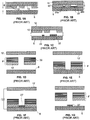
- FIG. 1A shows a side view of a CC mask 8 consisting of a conformable or deformable (e.g. elastomeric) insulator 10 patterned on an anode 12.
- the anode has two functions. One is as a supporting material for the patterned insulator 10 to maintain its integrity and alignment since the pattern may be topologically complex (e.g., involving isolated "islands" of insulator material). The other function is as an anode for the electroplating operation.
- FIG. 1A also depicts a substrate 6, separated from mask 8, onto which material will be deposited during the process of forming a layer.
- CC mask plating selectively deposits material 22 onto substrate 6 by simply pressing the insulator against the substrate then electrodepositing material through apertures 26a and 26b in the insulator as shown in FIG. 1B . After deposition, the CC mask is separated, preferably non-destructively, from the substrate 6 as shown in FIG. 1C .
- the CC mask plating process is distinct from a "through-mask" plating process in that in a through-mask plating process the separation of the masking material from the substrate would occur destructively. Furthermore in a through mask plating process, opening in the masking material are typically formed while the masking material is in contact with and adhered to the substrate. As with through-mask plating, CC mask plating deposits material selectively and simultaneously over the entire layer.
- the plated region may consist of one or more isolated plating regions where these isolated plating regions may belong to a single structure that is being formed or may belong to multiple structures that are being formed simultaneously. In CC mask plating as individual masks are not intentionally destroyed in the removal process, they may be usable in multiple plating operations.
- FIGS. 1D - 1G Another example of a CC mask and CC mask plating is shown in FIGS. 1D - 1G.
- FIG. 1D shows an anode 12' separated from a mask 8' that includes a patterned conformable material 10' and a support structure 20.
- FIG. 1D also depicts substrate 6 separated from the mask 8'.
- FIG. 1E illustrates the mask 8' being brought into contact with the substrate 6.
- FIG. 1F illustrates the deposit 22' that results from conducting a current from the anode 12' to the substrate 6.
- FIG. 1G illustrates the deposit 22' on substrate 6 after separation from mask 8'.
- an appropriate electrolyte is located between the substrate 6 and the anode 12' and a current of ions coming from one or both of the solution and the anode are conducted through the opening in the mask to the substrate where material is deposited.
- This type of mask may be referred to as an anodeless INSTANT MASKTM (AIM) or as an anodeless conformable contact (ACC) mask.
- CC mask plating allows CC masks to be formed completely separate from the substrate on which plating is to occur (e.g. separate from a three-dimensional (3D) structure that is being formed).
- CC masks may be formed in a variety of ways, for example, using a photolithographic process. All masks can be generated simultaneously, e.g. prior to structure fabrication rather than during it. This separation makes possible a simple, low-cost, automated, self-contained, and internally-clean "desktop factory" that can be installed almost anywhere to fabricate 3D structures, leaving any required clean room processes, such as photolithography to be performed by service bureaus or the like.
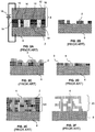
- FIGS. 2A - 2F An example of the electrochemical fabrication process discussed above is illustrated in FIGS. 2A - 2F .
- the CC mask 8 in this example, includes a patterned conformable material (e.g. an elastomeric dielectric material) 10 and a support 12 which is made from deposition material 2.
- the conformal portion of the CC mask is pressed against substrate 6 with a plating solution 14 located within the openings 16 in the conformable material 10.
- An electric current, from power supply 18, is then passed through the plating solution 14 via (a) support 12 which doubles as an anode and (b) substrate 6 which doubles as a cathode.
- FIG. 2A illustrates that the passing of current causes material 2 within the plating solution and material 2 from the anode 12 to be selectively transferred to and plated on the substrate 6.
- the CC mask 8 is removed as shown in FIG. 2B.
- FIG. 2C depicts the second deposition material 4 as having been blanket-deposited (i.e. non-selectively deposited) over the previously deposited first deposition material 2 as well as over the other portions of the substrate 6.
- the blanket deposition occurs by electroplating from an anode (not shown), composed of the second material, through an appropriate plating solution (not shown), and to the cathode/substrate 6.
- the entire two-material layer is then planarized to achieve precise thickness and flatness as shown in FIG. 2D .
- the multi-layer structure 20 formed of the second material 4 i.e. structural material
- first material 2 i.e. sacrificial material
- the embedded structure is etched to yield the desired device, i.e. structure 20, as shown in FIG. 2F .
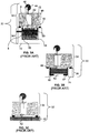
- FIGS. 3A - 3C Various components of an exemplary manual electrochemical fabrication system 32 are shown in FIGS. 3A - 3C .
- the system 32 consists of several subsystems 34, 36, 38, and 40.
- the substrate holding subsystem 34 is depicted in the upper portions of each of FIGS. 3A - 3C and includes several components: (1) a carrier 48, (2) a metal substrate 6 onto which the layers are deposited, and (3) a linear slide 42 capable of moving the substrate 6 up and down relative to the carrier 48 in response to drive force from actuator 44.
- Subsystem 34 also includes an indicator 46 for measuring differences in vertical position of the substrate which may be used in setting or determining layer thicknesses and/or deposition thicknesses.
- the subsystem 34 further includes feet 68 for carrier 48 which can be precisely mounted on subsystem 36.
- the CC mask subsystem 36 shown in the lower portion of FIG. 3A includes several components: (1) a CC mask 8 that is actually made up of a number of CC masks (i.e. submasks) that share a common support/anode 12, (2) precision X-stage 54, (3) precision Y-stage 56, (4) frame 72 on which the feet 68 of subsystem 34 can mount, and (5) a tank 58 for containing the electrolyte 16.
- Subsystems 34 and 36 also include appropriate electrical connections (not shown) for connecting to an appropriate power source (not shown) for driving the CC masking process.
- the blanket deposition subsystem 38 is shown in the lower portion of FIG. 3B and includes several components: (1) an anode 62, (2) an electrolyte tank 64 for holding plating solution 66, and (3) frame 74 on which feet 68 of subsystem 34 may sit. Subsystem 38 also includes appropriate electrical connections (not shown) for connecting the anode to an appropriate power supply (not shown) for driving the blanket deposition process.
- the planarization subsystem 40 is shown in the lower portion of FIG. 3C and includes a lapping plate 52 and associated motion and control systems (not shown) for planarizing the depositions.
- the '630 patent also teaches that the CC masks may be placed against a substrate with the polarity of the voltage reversed and material may thereby be selectively removed from the substrate. It indicates that such removal processes can be used to selectively etch, engrave, and polish a substrate, e.g., a plaque.
- the '630 patent further indicates that the electroplating methods and articles disclosed therein allow fabrication of devices from thin layers of materials such as, e.g., metals, polymers, ceramics, and semiconductor materials. It further indicates that although the electroplating embodiments described therein have been described with respect to the use of two metals, a variety of materials, e.g., polymers, ceramics and semiconductor materials, and any number of metals can be deposited either by the electroplating methods therein, or in separate processes that occur throughout the electroplating method. It indicates that a thin plating base can be deposited, e.g., by sputtering, over a deposit that is insufficiently conductive (e.g., an insulating layer) so as to enable subsequent electroplating. It also indicates that multiple support materials (i.e. sacrificial materials) can be included in the electroplated element allowing selective removal of the support materials.
- materials such as, e.g., metals, polymers, ceramics, and semiconductor materials.
- the '630 patent additionally teaches that the electroplating methods disclosed therein can be used to manufacture elements having complex microstructure and close tolerances between parts.
- An example is given with the aid of FIGS. 14A - 14E of that patent.
- elements having parts that fit with close tolerances e.g., having gaps between about 1-5 um, including electroplating the parts of the device in an unassembled, preferably pre-aligned, state and once fabricated.
- the individual parts can be moved into operational relation with each other or they can simply fall together. Once together the separate parts may be retained by clips or the like.
- the exposed surface of the secondary metal is then machined down to a height which exposes the first metal to produce a flat uniform surface extending across both the primary and secondary metals.
- Formation of a second layer may then begin by applying a photoresist over the first layer and patterning it (i.e. to form a second through mask) and then repeating the process that was used to produce the first layer to produce a second layer of desired configuration. The process is repeated until the entire structure is formed and the secondary metal is removed by etching.
- the photoresist is formed over the plating base or previous layer by casting and patterning of the photoresist (i.e. voids formed in the photoresist) are formed by exposure of the photoresist through a patterned mask via X-rays or UV radiation and development of the exposed or unexposed areas.
- the '637 patent teaches the locating of a plating base onto a substrate in preparation for electroplating materials onto the substrate.
- the plating base is indicated as typically involving the use of a sputtered film of an adhesive metal, such as chromium or titanium, and then a sputtered film of the metal that is to be plated.
- the plating base may be applied over an initial layer of sacrificial material (i.e. a layer or coating of a single material) on the substrate so that the structure and substrate may be detached if desired. In such cases after formation of the structure the sacrificial material forming part of each layer of the structure may be removed along the initial sacrificial layer to free the structure.
- Substrate materials mentioned in the '637 patent include silicon, glass, metals, and silicon with protected semiconductor devices.
- a specific example of a plating base includes about 150 angstroms of titanium and about 300 angstroms of nickel, both of which are sputtered at a temperature of 160°C. In another example it is indicated that the plating base may consist of 150 angstroms of titanium and 150 angstroms of nickel where both are applied by sputtering.
- Electrochemical Fabrication provides the ability to form prototypes and commercial quantities of miniature objects, parts, structures, devices, and the like at reasonable costs and in reasonable times. In fact, Electrochemical Fabrication is an enabler for the formation of many structures that were hitherto impossible to produce. Electrochemical Fabrication opens the spectrum for new designs and products in many industrial fields. Even though Electrochemical Fabrication offers this new capability and it is understood that Electrochemical Fabrication techniques can be combined with designs and structures known within various fields to produce new structures, certain uses for Electrochemical Fabrication provide designs, structures, capabilities and/or features not known or obvious in view of the state of the art.
- Planing devices can be used to surface thin layers of tissue, e.g. for removing scars from the surface of the skin.
- Conventional planing devices include at least one sharp edge that can be translated across the tissue to remove the top-most layer.
- Such cutting surfaces in conventional planing devices generally have dimensions that are too large to cut thin slices of tissue, e.g. to cut slices of tissue having a thickness less than 50 ⁇ m, and these devices therefore cannot precisely remove small areas of tissue.
- Coring devices can be used for biopsying tissue.
- Conventional coring devices generally include a needle that bores into the tissue.
- Conventional coring devices tend to cause pulling of and damage to surrounding tissue as the needle is pushed in. The rapid forward movement of the needle can also push aside the target tissue, such as a suspected tumor, especially if the target tissue is firmer than the surrounding tissue.
- conventional coring devices do not have small enough feature sizes to remove only small tissue particles, again resulting in excessive damage to surrounding tissue.
- Milling devices such as debriders
- debriders can be used for de-bulking, e.g. for surgical removal of a malignant tumor.
- Conventional debriders include a rounded or pointed distal end to aid in removing specific tissue.
- Such conventional milling devices are disadvantageous in that they often remove too much tissue and, due to their rounded ends, cannot selectively remove surface tissue. Further, conventional milling devices have dimensions that are generally too large to precisely remove small areas of tissue.
- Drilling devices such as atherectomy devices, are used to cut through tissue in the body.
- atherectomy devices are used to treat atherosclerosis, in which the arteries are obstructed due to the accumulation of plaque and neointimal hyperplasia.
- Such atherectomy devices work by cutting away or excising the obstructing plaque to help restore blood flow.
- Drilling devices are configured in a variety of ways, but generally include employing a rotatable and/or axially translatable cutting blade or abrasive end which can be advanced into the occluding material and rotated or translated to cut away the desired material.
- Conventional drilling devices however, have several drawbacks. Namely, the minimum feature size and shape of such devices, e.g.
- the size and shape of the cutting blades are often too large to cut specifically and precisely, such as down to a micrometer or cellular scale.
- such devices tend to either leave unwanted tissue in the body, such as plaque in the blood vessel, or cut too much tissue, thereby injuring surrounding tissue.
- traditional drilling devices have a fairly large diameter, e.g. over 2mm, and are not configured to fit into small lumens, such as blood vessels, having a smaller diameter. As a result, some areas in the body are unreachable by conventional drilling devices.
- tissue-cutting devices such as planing, coring, milling, or drilling devices, that can precisely cut tissue down to a micrometer or cellular scale.
- US 4,598,710 discloses a surgical cutting instrument having inner and outer tubes that have registrable openings at their distal ends and cutting edges formed about those openings for cutting tissue drawn into the openings by vacuum. The cutting action is provided by rotating the inner tube. This document is the closest prior art and discloses the preamble of claim 1.
- US 4,983,179 discloses a surgical cutting instrument having an outer tube that has an opening at its distal end and a cutting edge formed about the opening.
- a moveable internal member also having a cutting edge at its distal end, is mounted within the outer tube and when moved causes the cutting edges on the outer tube and those on the inner member to pass one another to cut tissue.
- US 2006/089662 discloses a cutting tool having inner and outer cutting tubes having registrable openings at their distal ends and cutting teeth arranged on opposite sides of each opening that cut tissue when the inner tube is rotated.
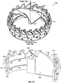
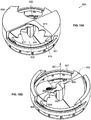
- the present invention provides a tissue cutting device according to claim 1.
- the elongate tube may have a diameter less than 5mm, at least one of the first and second annular elements may have a tooth having a radial thickness of less than 50 microns, and/or the flat portion may have an axial thickness of less than 100 microns.
- Some embodiments of the invention have an intake window at the distal end of the elongate tube.
- the first annular element is rotatable about the central axis in an opposite direction from the second annular element. In some embodiments, the first annular element is rotatable about the central axis in a same direction as the second annular element, and the first annular element and the second annular element being configured to be rotated at different speeds.
- the tissue cutting device includes a hole extending along the central axis.
- an ancillary component extending through the hole, such as an imaging element, a guide wire, a water jet tube, or a barbed device.
- Some embodiments also have a third annular element and a fourth annular element, the third and fourth annular elements located between the proximal and distal ends, at least one of the third or fourth annular elements configured to rotate, the rotation causing the third and fourth annular elements to rotate past each other to further shear the tissue.
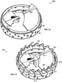
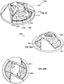
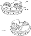
- first and second elements together form a conical shape at the distal end of the elongate tube; and wherein edges of the first and second tubular element are beveled to further shear tissue.
- the elongate tube may have a diameter less than 5 mm and the beveled edges may have a thickness less than 10 microns.
- the first and second elements together form a second conical shape, the second conical shape facing proximally.
- tissue cutting device may have an intake window at the distal end of the elongate tube.
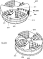
- the first and second annular elements each have an axially-extending cutting surface, the rotation causing the axially-extending surfaces of the first and second annular elements to pass each other to shear tissue, and wherein the first and second annular elements each have a radially-extending cutting surface, rotation causing the axially-extending surfaces of the first and second elements to pass each other to shear tissue, wherein the axially extending cutting surface has an axial length of less than 100 microns.
- the tissue cutting device may have teeth extending along the axially-extending or radially-extending cutting surfaces.
- the elongate tube may have a diameter less than 0.5mm.
- the first and second annular elements each include axially-extending teeth, the teeth having a radial thickness of less than 10 microns, the rotation causing the teeth of the first annular element and the teeth of the second annular element to pass each other to shear tissue.
- the elongate tube has a diameter less than 5 mm.
- the teeth have a pitch of less than 200 microns.
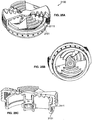
- the first annular element includes a plurality of first shearing elements, each first shearing element having a perpendicular shearing surface that is perpendicular to the central axis and the second annular element includes a plurality of second shearing elements, each second shearing element having a perpendicular shearing surface that is perpendicular to the central axis, wherein rotation of at least one of the first or second annular elements about the central axis causes the perpendicular shearing surfaces of the first shearing elements and the perpendicular shearing surfaces of the second shearing elements to pass each other to shear tissue.
- the elongate tube may have a diameter of less than 5 mm.
- At least some of the perpendicular shearing surfaces of the first shearing elements lie along the same plane and, optionally, at least some of the perpendicular shearing surfaces are located at the same radial distance from the central axis.
- At least some of the perpendicular shearing surfaces do not lie along the same plane and, optionally, at least some perpendicular shearing surfaces are located at different radial distances from the central axis.
- each first shearing element has a parallel shearing surface that is parallel to the central axis; wherein each second shearing element has a parallel shearing surface that is parallel to the central axis; and wherein rotation of the second annular element causes the causes the parallel shearing surfaces of the first shearing elements and the parallel shearing surfaces of the second shearing elements to pass each other to shear tissue.
- at least some of the parallel shearing surfaces of the first shearing elements lie along the same radial plane and, optionally, the at least some parallel shearing surfaces are spaced apart from each other circumferentially. In some embodiments, at least some of the parallel shearing surfaces of the first shearing elements are spaced apart from each other radially.
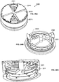
- the first annular element includes a plurality of first shearing elements, each first shearing element having a parallel shearing surface that is parallel to the central axis and the second annular element includes a plurality of second shearing elements, each second shearing element having a parallel shearing surface that is parallel to the central axis, wherein rotation of at least one of the first or second annular elements about the central axis causes the parallel shearing surfaces of the first shearing elements and the parallel shearing surfaces of the second shearing elements to pass each other to shear tissue.
- At least some of the parallel shearing surfaces of the first shearing elements lie along the same radial plane. In some such embodiments, the at least some of the parallel shearing surfaces are spaced apart from each other axially and, optionally, the at least some of the parallel shearing surfaces are spaced apart from each other circumferentially.
- the elongate tube may have a diameter of less than 5 mm.
- At least one surface can be perpendicular to the central axis. At least one surface can be parallel to the central axis. At least a portion of the at least one surface that is perpendicular can be located at the radial-most location of the first or second annular elements.
- the total radial length occupied by the at least one perpendicular surface can be at least 1/10, such as at least 1/5, such as at least 1/4, such as at least 1/3, such as at least 1/2 of the radius of the cutting device.
- the at least one surface can be spaced apart from the central axis. There can be at least two surfaces occupy different planes which are perpendicular to the central axis.
- first shearing element and the second shearing element can be less than 20 microns, such as less than 10 microns, such as less than 5 microns, such as approximately 1 micron.
- the first and second shearing elements can be in contact when passing each other.
- the shearing elements can be substantially parallel to the central axis.
- the distance from the shearing element to the central axis can be less than 7/8 of the radius, such as less than 3/4 of the radius, such as less than 5/8 of the radius, such as less than 1/2 of the radius from the central axis.
- Each surface can have a plurality of shearing elements.
- the first annular element includes at least one first blade element.
- the at least one first blade element includes a first front surface and a first back surface, the first front surface including a first front shearing element, and the first back surface including a first back shearing element.
- the second annular element includes at least one second blade element.
- the at least one second blade element includes a second back surface and a second front surface.
- the second front surface includes a second front shearing element, and the second back surface includes a second back shearing element.
- the surfaces of the blades can be perpendicular to the central axis.
- the surfaces of the blades can be substantially parallel to the central axis.
- the first blade element can include at least one second blade element perpendicular to the first blade element.
- the distance between shearing elements of the first annular element and shearing elements of the second shearing elements can be less than 20 microns, such as less than 10 microns, such as less than 5 microns, such as approximately 1 micron.
- the shearing elements of the first annular element and the shearing elements of the second annular elements can be in contact when passing each other.
- the surfaces of the blades can have at least one tooth.
- each successively formed layer comprises at least two materials, one of which is a structural material and the other of which is a sacrificial material, and wherein each successive layer defines a successive cross-section of the three-dimensional structure, and wherein the forming of each of the plurality of successive layers includes: (i) depositing a first of the at least two materials; (ii) depositing a second of the at least two materials; and (B) after the forming of the plurality of successive layers, separating at least a portion of the sacrificial material from the structural material to reveal the three-dimensional structure
- FIGS. 1A - 1G , 2A - 2F, and 3A - 3C illustrate various features of one form of electrochemical fabrication.
- Other electrochemical fabrication techniques are set forth in the '630 patent referenced above, and in the various previously referenced publications, patents and patent applications. Still others may be derived from combinations of various approaches described in these publications, patents, and applications, or are otherwise known or ascertainable by those of skill in the art from the teachings set forth herein. All of these techniques may be combined with those of the various embodiments of various aspects of the invention to yield enhanced embodiments. Still other embodiments may be derived from combinations of the various embodiments explicitly set forth herein.
- FIGS. 4A - 4I illustrate various stages in the formation of a single layer of a multi-layer fabrication process where a second metal is deposited on a first metal as well as in openings in the first metal so that the first and second metal form part of the layer.
- a side view of a substrate 82 is shown, onto which patternable photoresist 84 is cast as shown in FIG. 4B .
- a pattern of resist is shown that results from the curing, exposing, and developing of the resist.
- the patterning of the photoresist 84 results in openings or apertures 92(a) - 92(c) extending from a surface 86 of the photoresist through the thickness of the photoresist to surface 88 of the substrate 82.
- a metal 94 e.g. nickel
- FIG. 4E the photoresist has been removed (i.e. chemically stripped) from the substrate to expose regions of the substrate 82 which are not covered with the first metal 94.
- a second metal 96 e.g.
- FIG. 4G depicts the completed first layer of the structure which has resulted from the planarization of the first and second metals down to a height that exposes the first metal and sets a thickness for the first layer.
- FIG. 4H the result of repeating the process steps shown in FIGS. 4B - 4 G several times to form a multi-layer structure are shown where each layer consists of two materials. For most applications, one of these materials is removed as shown in FIG. 4I to yield a desired 3-D structure 98 (e.g. component or device).
- Various embodiments of various aspects of the invention are directed to formation of three-dimensional structures from materials some of which may be electrodeposited or electroless deposited. Some of these structures may be formed form a single build level formed from one or more deposited materials while others are formed from a plurality of build layers each including at least two materials (e.g. two or more layers, more preferably five or more layers, and most preferably ten or more layers). In some embodiments, layer thicknesses may be as small as one micron or as large as fifty microns. In other embodiments, thinner layers may be used while in other embodiments, thicker layers may be used. In some embodiments structures having features positioned with micron level precision and minimum features size on the order of tens of microns are to be formed.
- mesoscale and millimeter scale have the same meaning and refer to devices that may have one or more dimensions extending into the 0.5 - 20 millimeter range, or somewhat larger and with features positioned with precision in the 10-100 micron range and with minimum features sizes on the order of 100 microns.
- Various embodiments, alternatives, and techniques disclosed herein may form multi-layer structures using a single patterning technique on all layers or using different patterning techniques on different layers.
- Various embodiments of the invention may perform selective patterning operations using conformable contact masks and masking operations (i.e. operations that use masks which are contacted to but not adhered to a substrate), proximity masks and masking operations (i.e. operations that use masks that at least partially selectively shield a substrate by their proximity to the substrate even if contact is not made), non-conformable masks and masking operations (i.e.
- Conformable contact masks, proximity masks, and non-conformable contact masks share the property that they are preformed and brought to, or in proximity to, a surface which is to be treated (i.e. the exposed portions of the surface are to be treated). These masks can generally be removed without damaging the mask or the surface that received treatment to which they were contacted, or located in proximity to.
- Adhered masks are generally formed on the surface to be treated (i.e.
- Adhered masks may be formed in a number of ways including (1) by application of a photoresist, selective exposure of the photoresist, and then development of the photoresist, (2) selective transfer of pre-patterned masking material, and/or (3) direct formation of masks from computer controlled depositions of material.
- Patterning operations may be used in selectively depositing material and/or may be used in the selective etching of material.
- Selectively etched regions may be selectively filled in or filled in via blanket deposition, or the like, with a different desired material.
- the layer-by-layer build up may involve the simultaneous formation of portions of multiple layers.
- depositions made in association with some layer levels may result in depositions to regions associated with other layer levels (i.e. regions that lie within the top and bottom boundary levels that define a different layer's geometric configuration).
- Such use of selective etching and interlaced material deposition in association with multiple layers is described in US Patent 7,252,861 ,
- Temporary substrates on which structures may be formed may be of the sacrificial-type (i.e. destroyed or damaged during separation of deposited materials to the extent they cannot be reused), non-sacrificial-type (i.e. not destroyed or excessively damaged, i.e. not damaged to the extent they may not be reused, e.g. with a sacrificial or release layer located between the substrate and the initial layers of a structure that is formed).
- Non-sacrificial substrates may be considered reusable, with little or no rework (e.g. replanarizing one or more selected surfaces or applying a release layer, and the like) though they may or may not be reused for a variety of reasons.
- Build refers, as a verb, to the process of building a desired structure or plurality of structures from a plurality of applied or deposited materials which are stacked and adhered upon application or deposition or, as a noun, to the physical structure or structures formed from such a process.
- such physical structures may include a desired structure embedded within a sacrificial material or may include only desired physical structures which may be separated from one another or may require dicing and/or slicing to cause separation.
- Build axis or “build orientation” is the axis or orientation that is substantially perpendicular to substantially planar levels of deposited or applied materials that are used in building up a structure.
- the planar levels of deposited or applied materials may be or may not be completely planar but are substantially so in that the overall extent of their cross-sectional dimensions are significantly greater than the height of any individual deposit or application of material (e.g. 100, 500, 1000, 5000, or more times greater).
- the planar nature of the deposited or applied materials may come about from use of a process that leads to planar deposits or it may result from a planarization process (e.g. a process that includes mechanical abrasion, e.g.
- vertical refers to the build axis or nominal build axis (if the layers are not stacking with perfect registration) while “horizontal” refers to a direction within the plane of the layers (i.e. the plane that is substantially perpendicular to the build axis).
- Build layer or "layer of structure” as used herein does not refer to a deposit of a specific material but instead refers to a region of a build located between a lower boundary level and an upper boundary level which generally defines a single cross-section of a structure being formed or structures which are being formed in parallel.
- build layers are generally formed on and adhered to previously formed build layers.
- the boundaries between build layers are defined by planarization operations which result in successive build layers being formed on substantially planar upper surfaces of previously formed build layers.
- the substantially planar upper surface of the preceding build layer may be textured to improve adhesion between the layers.
- openings may exist in or be formed in the upper surface of a previous but only partially formed build layers such that the openings in the previous build layers are filled with materials deposited in association with current build layers which will cause interlacing of build layers and material deposits.
- Such interlacing is described in U.S. Patent Application No. 10/434,519 now patent 7,252,861 .
- a build layer includes at least one primary structural material and at least one primary sacrificial material.
- two or more primary structural materials may be used without a primary sacrificial material (e.g. when one primary structural material is a dielectric and the other is a conductive material).
- build layers are distinguishable from each other by the source of the data that is used to yield patterns of the deposits, applications, and/or etchings of material that form the respective build layers. For example, data descriptive of a structure to be formed which is derived from data extracted from different vertical levels of a data representation of the structure define different build layers of the structure. The vertical separation of successive pairs of such descriptive data may define the thickness of build layers associated with the data.
- deposition thickness of primary structural or sacrificial materials is generally greater than the layer thickness and a net deposit thickness is set via one or more planarization processes which may include, for example, mechanical abrasion (e.g. lapping, fly cutting, polishing, and the like) and/or chemical etching (e.g. using selective or non-selective etchants).
- planarization processes may include, for example, mechanical abrasion (e.g. lapping, fly cutting, polishing, and the like) and/or chemical etching (e.g. using selective or non-selective etchants).
- the lower boundary and upper boundary for a build layer may be set and defined in different ways. From a design point of view they may be set based on a desired vertical resolution of the structure (which may vary with height).
- the vertical layer boundaries may be defined as the vertical levels at which data descriptive of the structure is processed or the layer thickness may be defined as the height separating successive levels of cross-sectional data that dictate how the structure will be formed.
- the upper and lower layer boundaries may be defined in a variety of different ways. For example by planarization levels or effective planarization levels (e.g. lapping levels, fly cutting levels, chemical mechanical polishing levels, mechanical polishing levels, vertical positions of structural and/or sacrificial materials after relatively uniform etch back following a mechanical or chemical mechanical planarization process). For example, by levels at which process steps or operations are repeated. At levels at which, at least theoretically, lateral extends of structural material can be changed to define new cross-sectional features of a structure.
- Layer thickness is the height along the build axis between a lower boundary of a build layer and an upper boundary of that build layer.
- Planarization is a process that tends to remove materials, above a desired plane, in a substantially non-selective manner such that all deposited materials are brought to a substantially common height or desired level (e.g. within 20%, 10%, 5%, or even 1% of a desired layer boundary level).
- lapping removes material in a substantially non-selective manner though some amount of recession one material or another may occur (e.g. copper may recess relative to nickel).
- Planarization may occur primarily via mechanical means, e.g. lapping, grinding, fly cutting, milling, sanding, abrasive polishing, frictionally induced melting, other machining operations, or the like (i.e. mechanical planarization).
- Mechanical planarization maybe followed or proceeded by thermally induced planarization (.e.g. melting) or chemically induced planarization (e.g. etching). Planarization may occur primarily via a chemical and/or electrical means (e.g. chemical etching, electrochemical etching, or the like). Planarization may occur via a simultaneous combination of mechanical and chemical etching (e.g. chemical mechanical polishing (CMP)).
- CMP chemical mechanical polishing
- Structural material refers to a material that remains part of the structure when put into use.
- “Supplemental structural material” as used herein refers to a material that forms part of the structure when the structure is put to use but is not added as part of the build layers but instead is added to a plurality of layers simultaneously (e.g. via one or more coating operations that applies the material, selectively or in a blanket fashion, to a one or more surfaces of a desired build structure that has been released from a sacrificial material.
- Primary structural material as used herein is a structural material that forms part of a given build layer and which is typically deposited or applied during the formation of that build layer and which makes up more than 20% of the structural material volume of the given build layer.
- the primary structural material may be the same on each of a plurality of build layers or it may be different on different build layers.
- a given primary structural material may be formed from two or more materials by the alloying or diffusion of two or more materials to form a single material.
- Secondary structural material as used herein is a structural material that forms part of a given build layer and is typically deposited or applied during the formation of the given build layer but is not a primary structural material as it individually accounts for only a small volume of the structural material associated with the given layer.
- a secondary structural material will account for less than 20% of the volume of the structural material associated with the given layer. In some preferred embodiments, each secondary structural material may account for less than 10%, 5%, or even 2% of the volume of the structural material associated with the given layer.
- Examples of secondary structural materials may include seed layer materials, adhesion layer materials, barrier layer materials (e.g. diffusion barrier material), and the like.
- These secondary structural materials are typically applied to form coatings having thicknesses less than 2 microns, 1 micron, 0.5 microns, or even 0.2 microns).
- the coatings may be applied in a conformal or directional manner (e.g. via CVD, PVD, electroless deposition, or the like). Such coatings may be applied in a blanket manner or in a selective manner. Such coatings may be applied in a planar manner (e.g. over previously planarized layers of material) as taught in US Patent Application 10/607,931 , now patent 7,239,219 .
- such coatings may be applied in a non-planar manner, for example, in openings in and over a patterned masking material that has been applied to previously planarized layers of material as taught in US Patent Application 10/841,383 , now patent 7,195,989 .
- “Functional structural material” as used herein is a structural material that would have been removed as a sacrificial material but for its actual or effective encapsulation by other structural materials. Effective encapsulation refers, for example, to the inability of an etchant to attack the functional structural material due to inaccessibility that results from a very small area of exposure and/or due to an elongated or tortuous exposure path. For example, large (10,000 ⁇ m 2 ) but thin (e.g. less than 0.5 microns) regions of sacrificial copper sandwiched between deposits of nickel may define regions of functional structural material depending on ability of a release etchant to remove the sandwiched copper.
- Sacrificial material is material that forms part of a build layer but is not a structural material. Sacrificial material on a given build layer is separated from structural material on that build layer after formation of that build layer is completed and more generally is removed from a plurality of layers after completion of the formation of the plurality of layers during a "release" process that removes the bulk of the sacrificial material or materials. In general sacrificial material is located on a build layer during the formation of one, two, or more subsequent build layers and is thereafter removed in a manner that does not lead to a planarized surface. Materials that are applied primarily for masking purposes, i.e. to allow subsequent selective deposition or etching of a material, e.g.
- photoresist that is used in forming a build layer but does not form part of the build layer) or that exist as part of a build for less than one or two complete build layer formation cycles are not considered sacrificial materials as the term is used herein but instead shall be referred as masking materials or as temporary materials.
- These separation processes are sometimes referred to as a release process and may or may not involve the separation of structural material from a build substrate.
- sacrificial material within a given build layer is not removed until all build layers making up the three-dimensional structure have been formed.
- sacrificial material may be, and typically is, removed from above the upper level of a current build layer during planarization operations during the formation of the current build layer.
- Sacrificial material is typically removed via a chemical etching operation but in some embodiments may be removed via a melting operation or electrochemical etching operation.
- the removal of the sacrificial material i.e. release of the structural material from the sacrificial material
- the removal of the sacrificial material does not result in planarized surfaces but instead results in surfaces that are dictated by the boundaries of structural materials located on each build layer.
- Sacrificial materials are typically distinct from structural materials by having different properties therefrom (e.g. chemical etchability, hardness, melting point, etc.) but in some cases, as noted previously, what would have been a sacrificial material may become a structural material by its actual or effective encapsulation by other structural materials.
- structural materials may be used to form sacrificial structures that are separated from a desired structure during a release process via the sacrificial structures being only attached to sacrificial material or potentially by dissolution of the sacrificial structures themselves using a process that is insufficient to reach structural material that is intended to form part of a desired structure.
- small amounts of structural material may be removed, after or during release of sacrificial material. Such small amounts of structural material may have been inadvertently formed due to imperfections in the fabrication process or may result from the proper application of the process but may result in features that are less than optimal (e.g. layers with stairs steps in regions where smooth sloped surfaces are desired.
- the volume of structural material removed is typically minuscule compared to the amount that is retained and thus such removal is ignored when labeling materials as sacrificial or structural.
- Sacrificial materials are typically removed by a dissolution process, or the like, that destroys the geometric configuration of the sacrificial material as it existed on the build layers.
- the sacrificial material is a conductive material such as a metal.
- masking materials though typically sacrificial in nature are not termed sacrificial materials herein unless they meet the required definition of sacrificial material.
- “Supplemental sacrificial material” as used herein refers to a material that does not form part of the structure when the structure is put to use and is not added as part of the build layers but instead is added to a plurality of layers simultaneously (e.g. via one or more coating operations that applies the material, selectively or in a blanket fashion, to a one or more surfaces of a desired build structure that has been released from an initial sacrificial material.
- This supplemental sacrificial material will remain in place for a period of time and/or during the performance of certain post layer formation operations, e.g. to protect the structure that was released from a primary sacrificial material, but will be removed prior to putting the structure to use.
- Primary sacrificial material as used herein is a sacrificial material that is located on a given build layer and which is typically deposited or applied during the formation of that build layer and which makes up more than 20% of the sacrificial material volume of the given build layer.
- the primary sacrificial material may be the same on each of a plurality of build layers or may be different on different build layers.
- a given primary sacrificial material may be formed from two or more materials by the alloying or diffusion of two or more materials to form a single material.
- Secondary sacrificial material as used herein is a sacrificial material that is located on a given build layer and is typically deposited or applied during the formation of the build layer but is not a primary sacrificial materials as it individually accounts for only a small volume of the sacrificial material associated with the given layer.
- a secondary sacrificial material will account for less than 20% of the volume of the sacrificial material associated with the given layer.
- each secondary sacrificial material may account for less than 10%, 5%, or even 2% of the volume of the sacrificial material associated with the given layer.
- Examples of secondary structural materials may include seed layer materials, adhesion layer materials, barrier layer materials (e.g.
- These secondary sacrificial materials are typically applied to form coatings having thicknesses less than 2 microns, 1 micron, 0.5 microns, or even 0.2 microns).
- the coatings may be applied in a conformal or directional manner (e.g. via CVD, PVD, electroless deposition, or the like). Such coatings may be applied in a blanket manner or in a selective manner. Such coatings may be applied in a planar manner (e.g. over previously planarized layers of material) as taught in US Patent Application 10/607,931 , now patent 7,239,219 .
- such coatings may be applied in a non-planar manner, for example, in openings in and over a patterned masking material that has been applied to previously planarized layers of material as taught in US Patent Application 10/841,383 , now patent 7,195,989 .
- Adhesion layer refers to coatings of material that are thin in comparison to the layer thickness and thus generally form secondary structural material portions or sacrificial material portions of some layers. Such coatings may be applied uniformly over a previously formed build layer, they may be applied over a portion of a previously formed build layer and over patterned structural or sacrificial material existing on a current (i.e. partially formed) build layer so that a non-planar seed layer results, or they may be selectively applied to only certain locations on a previously formed build layer.
- selected portions may be removed (1) prior to depositing either a sacrificial material or structural material as part of a current layer or (2) prior to beginning formation of the next layer or they may remain in place through the layer build up process and then etched away after formation of a plurality of build layers.
- Masking material is a material that may be used as a tool in the process of forming a build layer but does not form part of that build layer.
- Masking material is typically a photopolymer or photoresist material or other material that may be readily patterned.
- Masking material is typically a dielectric.
- Masking material though typically sacrificial in nature, is not a sacrificial material as the term is used herein.
- Masking material is typically applied to a surface during the formation of a build layer for the purpose of allowing selective deposition, etching, or other treatment and is removed either during the process of forming that build layer or immediately after the formation of that build layer.
- Multilayer structures are structures formed from multiple build layers of deposited or applied materials.
- Multilayer three-dimensional (or 3D or 3-D) structures are Multilayer Structures that meet at least one of two criteria: (1) the structural material portion of at least two layers of which one has structural material portions that do not overlap structural material portions of the other.
- Complex multilayer three-dimensional (or 3D or 3-D) structures are multilayer three-dimensional structures formed from at least three layers where a line may be defined that hypothetically extends vertically through at least some portion of the build layers of the structure will extend from structural material through sacrificial material and back through structural material or will extend from sacrificial material through structural material and back through sacrificial material (these might be termed vertically complex multilayer three-dimensional structures).
- complex multilayer three-dimensional structures may be defined as multilayer three-dimensional structures formed from at least two layers where a line may be defined that hypothetically extends horizontally through at least some portion of a build layer of the structure that will extend from structural material through sacrificial material and back through structural material or will extend from sacrificial material through structural material and back through sacrificial material (these might be termed horizontally complex multilayer three-dimensional structures).
- a vertically or horizontally extending hypothetical line will extend from one or structural material or void (when the sacrificial material is removed) to the other of void or structural material and then back to structural material or void as the line is traversed along at least a portion of the line.
- Moderately complex multilayer three-dimensional (or 3D or 3-D) structures are complex multilayer 3D structures for which the alternating of void and structure or structure and void not only exists along one of a vertically or horizontally extending line but along lines extending both vertically and horizontally.
- Highly complex multilayer (or 3D or 3-D) structures are complex multilayer 3D structures for which the structure-to-void-to-structure or void-to-structure-to-void alternating occurs once along the line but occurs a plurality of times along a definable horizontally or vertically extending line.
- Up-facing feature is an element dictated by the cross-sectional data for a given build layer “n” and a next build layer “n+1” that is to be formed from a given material that exists on the build layer “n” but does not exist on the immediately succeeding build layer “n+1".
- up-facing feature will apply to such features regardless of the build orientation.
- Down-facing feature is an element dictated by the cross-sectional data for a given build layer “n” and a preceding build layer “n-1” that is to be formed from a given material that exists on build layer “n” but does not exist on the immediately preceding build layer “n-1".
- the term “down-facing feature” shall apply to such features regardless of the actual build orientation.
- Continuing region is the portion of a given build layer “n” that is dictated by the cross-sectional data for the given build layer “n”, a next build layer “n+1” and a preceding build layer “n-1" that is neither up-facing nor down-facing for the build layer "n”.
- Minimum feature size refers to a necessary or desirable spacing between structural material elements on a given layer that are to remain distinct in the final device configuration. If the minimum feature size is not maintained on a given layer, the fabrication process may result in structural material inadvertently bridging the two structural elements due to masking material failure or failure to appropriately fill voids with sacrificial material during formation of the given layer such that during formation of a subsequent layer structural material inadvertently fills the void. More care during fabrication can lead to a reduction in minimum feature size or a willingness to accept greater losses in productivity can result in a decrease in the minimum feature size.
- a minimum design feature size is set in one way or another.
- the above described minimum feature size may more appropriately be termed minimum feature size of sacrificial material regions.
- a minimum feature size for structure material regions may be specified.
- the two types of minimum feature sizes may be different.
- the minimum features size on a given layer may be roughly set to a value that approximates the layer thickness used to form the layer and it may be considered the same for both structural and sacrificial material widths and lengths. In some more rigorously implemented processes, examination regiments, and rework requirements, it may be set to an amount that is 80%, 50%, or even 30% of the layer thickness. Other values or methods of setting minimum feature sizes may be set.
- Sublayer refers to a portion of a build layer that typically includes the full lateral extents of that build layer but only a portion of its height.
- a sublayer is usually a vertical portion of build layer that undergoes independent processing compared to another sublayer of that build layer.
- tissue removal methods such as planing, coring, milling, or drilling.
- tissue removal methods can be used in various applications including: (1) Disc, other tissue, or bone in the spinal region, for example, to relieve pressure on spinal nerves, (2) Ear, nose (sinus), and throat surgery, (3) ophthalmic procedures such as cataract surgery; (4) Cardiovascular (can be delivered over a guide wire) surgery or procedures such as (a) Blood clot removal (Thrombectomy); (b) Chronic total occlusion (CTO); (c) Atherectomy; (d) Removal of heart tissue; (5) Neurovascular procedures such as thrombectomy; (6) Breast surgeries or procedures such as (a) Breast duct papilloma, and (b) Lumpectomy; (7) Orthopedic surgeries and procedures such as (a) Joint surgeries; (b) Removal of bone spurs; and (c) Arthroscopic surgeries; (8) Peripheral artery disease surgeries and procedures;
- the cutting devices described herein can advantageously be constructed using the electrochemical fabrication process.
- Using the electrochemical fabrication process allows the devices to be on the micrometer or nanometer scale and have precision on the order of tens of microns. Medical devices having such scale and precision are advantageous over conventional medical devices because they can be sharper, have more cutting surfaces, and be more intricately shaped. As a result, the medical devices described herein can be used for selective and accurate removal of tissue or other material within the body.
- the medical devices described herein may be used in conjunction with ancillary components extending through the center of the device, such as guide wires, endoscopes or other imaging methods (IVUS, OCT, OFDI, etc), aspiration, irrigation, and other micro-scale or millimeter-scale devices and instruments such as distal protection devices (see US Patent Application No. 12/179,573 ), positioning instruments such as expanders (see US Patent Application No. 12/179,573 ), other tissue shredding devices such as those described in US Patent Application No. 12/490,301 , and guiding and configurable elements such as those described in US Patent Application Nos. 12/169,528 ; 12/179,295 ; and 12/144,618 .
- ancillary components extending through the center of the device, such as guide wires, endoscopes or other imaging methods (IVUS, OCT, OFDI, etc), aspiration, irrigation, and other micro-scale or millimeter-scale devices and instruments such as distal protection devices (see US Patent
- the cutting devices described herein can each include two concentric components, which can be configured to rotate relative to one another to perform the desired surgical function. As such, only one concentric component can be rotated, both can be rotated in opposite directions, or both can be rotated in the same direction, but at different rates.
- the dimensions of the various cutting devices can be adjusted to obtain a desired degree of tissue removal.
- FIGS. 5A-5E illustrate a cutting device 100.
- the first component 101 of the device 100 includes an inner cutting element 102, having a primary cutting surface 103 and a secondary cutting surface 104.
- the second component 111 likewise includes an outer cutting element 112, having a primary surface 113 and a secondary surface 114.
- the first component 101 is capable of rotating relative to the second component 111, and the interaction of the cutting surfaces can cause shearing away of layers of tissue or other material as the inner and outer cutting elements rotate past one another.
- either or both components can be configured to rotate in either direction.
- the first component can rotate counter-clockwise, and the second component can rotate clockwise.
- Both the inner and outer cutters 102, 112 can have singled-sided substantially radially-extending primary cutting surfaces 103 and 113 as well as secondary cutting surfaces 104 and 114 extending substantially axially at the radial extremes of the components. Having a primary cutting surface extending substantially radially and a secondary cutting surface extending substantially axially can be advantageous over prior art cutting devices because it provides more cutting surfaces for shearing off tissue. Further, the axial length of the secondary cutting surfaces 104 and 114 can be less than 100 microns, such as less than 50 microns, such as less than 10 microns. Such a small axial length allows for accurate removal of small layers of tissue, such as layers between 2 and 5 microns thick. Thus, for example, cutting device 100 can be used for planing of thin slices of tissue.
- Teeth 105 and 115 can extend along the primary and/or the secondary cutting surfaces.
- the teeth 105 and 115 can all be configured such that they extend radially.
- the teeth 105 and 115 can be configured to, upon rotation of the first and second components 101, 111, engage one another substantially point-to-point, relative to a centered longitudinal axis 121 of relative rotation of the elements.
- the teeth 105 and 115 can aid in shearing off layers of tissue during the planing process.
- the cutting surface of the first component 101 is supported by a sloped surface that sweeps a three-dimensional curve (i.e. sweeping in radial, axial or longitudinal, and azimuthal directions).
- the proximal facing portion of this sloped surface when rotating in a counterclockwise direction, may aid in pushing sheared off material in a proximal and longitudinal direction to help remove material and ensure that the cutting surface of the blade is cleared of material and ready to shear off newly encountered material.
- the first component 101 of device 100 includes an intake window 122.
- the intake window 122 can, for example, extend across at least one-half of the distal end of the cutting device, such as approximately one-half of the distal end of the cutting device.
- the intake window 122 permits tissue to extend into the interior of cutting device 100 to enable the interacting cutting surfaces of the first and second components to shear the tissue, for example during a planing process.
- the components may be formed with a plurality of etching or release holes so that the individual components may be formed using a multi-material, multi-layer fabrication method and then the sacrificial material readily removed. In alternative embodiments, fewer, more, or even no release holes may be formed.
- the components may be formed using an interference bushings, or with intermediate bearing elements, for example, to provide smoother operation or tighter formation tolerances.
- fluid flow paths and outlets may exist between the components and may receive a fluid during operation of the device so as to provide a fluid bearing for improved device operation.
- the device 100 can be a micro-scale device.
- the diameter of the device 100 can be less than 5mm, such as less than 3mm, e.g. less than 1mm.
- the minimum feature size can be on the order of tens of microns, i.e. less than 100 microns, such as less than 50 microns.
- the precision of the device build can be on the micron level, i.e. between 1 and 10 microns. Having a micro-scale device can advantageously allow the device to be used in small areas of the body that are unreachable by larger devices.
- the precision of the build and the minimum feature size can be useful for very precise and specific tissue removal, such as planing of tissue layers of only a few microns thick.
- These micro-scale devices may be made using the electrochemical fabrication process described above.
- the teeth of the cutting elements may be made to encounter one another other than in a tip-to-tip configuration, the teeth may be removed in favor of straight blades, and the cutting blades may have cutting surfaces that have lengths which extend not just radially but also have an azimuthal component of length as well.
- the cutting elements may be provided with cutting surfaces to allow cutting in either direction of rotation.
- the intake opening, which is defined by the distal cap of component 111 may be made larger by decreasing the azimuthal sweep or extent of the cap or smaller by increasing the azimuthal extent of the cap.
- different numbers of inner cutting elements may form part of the inner component (e.g. 1, 2, 3, 4, or more cutting elements), and different numbers of outer cutting elements may form part of the outer component, and in some embodiments, these numbers of inner and outer cutting elements need not match.
- cutting elements may be contained on a single component, two components, or more than two components.
- the two components 101, 111 of this working end of the cutting device may have their proximal ends joined or otherwise coupled to tubes or other rotatable elements such that one component (i.e. each including its respective cutting elements) stays stationary while the other rotates, such the two components 101, 111 rotate in opposite directions, or such that the two components 101,111 rotate in the same direction but at different rates such that they still move past one another to provide shearing.
- the components 101,111 may be made to periodically, or possibly upon input from sensors (e.g. an input indicating a stall or excess slowing of the rotation), rotate a partial rotation in reverse to provide an opportunity for additional shearing attempts.
- the cutting may be accompanied by aspiration from distal to proximal end to provide enhanced transport of sheared off material.
- aspiration may be accompanied by appropriately directed irrigation.
- more proximally located cutting and/or transport elements can be included on the components 101, 111 to cause further maceration of the removed material or proximal transportation of the material.
- the rotation of one or both of the concentric components may occur via one or more rotating tubes that may be located within a catheter.
- the tubes may be driven by rotational driving elements located at a significant distance from the working area that is being operated on (e.g. outside the body of a patient).
- the rotating tubes or other elements may be driven by a fluid driven turbine (e.g. driven by an irrigation fluid of other fluid) that is located within the catheter or other instrumental lumen.
- instrument components shown in FIGS. 5A - 5E may be formed using one of the multi-layer multi-material fabrication processes set forth herein.
- one of the components, or part the components may be made by one of these multi-layer multi-material fabrication process while the other component or component portions may be made by one or more different processes.
- both of the components may be made by processes other than multi-layer, multi-material fabrication process.
- one or both components, or portions thereof may be made from a tube which is cut to a desired shape and then bent to a desired configuration and perhaps with portions welded or otherwise joined to maintain the created configuration.
- FIGS. 6A - 6C provide various views of a working end of a cutting device 200.
- the cutting device 200 includes first and second components 201 and 211.
- the first component 201 includes an inner cutting element 202, having a primary cutting surface 203 and a secondary cutting surface 204.
- the second component 211 includes an outer cutting element 212, having a primary surface 213 and a secondary surface 214.
- One or both of the first and second components 201, 211 is capable of rotating about a central longitudinal axis 221 to cause relative rotation with respect to one another.
- the interaction of cutting surfaces 203 and 204 with cutting surfaces 213 and 214, respectively, during such relative rotation can cause shearing away of tissue or other material as the inner and outer cutting elements rotate past one another.
- Both the inner and outer cutters 202, 212 can have singled-sided radial extending, and slightly azimuthal extending, primary cutting surfaces 203 and 213 as well as secondary cutting surfaces 204 and 214 extending axially at the radial extremes of the components. Teeth 205 and 215 can extend radially along the primary and/or secondary cutting surfaces.
- An intake window such as an intake window 222 of the device exists on one-half of the distal end of the cutting device 200.
- the intake window 222 permits tissue to extend into the interior of cutting device 200 to enable the interacting cutting surfaces of the first and second components to shear the tissue, for example during a planing process.
- a distal cap of element 211 is located on the other half of the distal end of the cutting device 200.
- the cutter 200 can have many of the same advantages of the cutter 100.
- the cutter 100 can be a micro-scale device and can have thin axially-extending cutting surfaces, allowing for access to small areas and specific and precise removal of very small layers of tissue, such as during a planing process.
- FIGS. 7A - 7B provide perspective and cut views of a working end of a cutting device 300.
- the first component 301 of the device 300 includes an inner cutting element 302 having optional teeth 305 that extend perpendicular to the axis of rotation and a secondary peripheral cutting surface 303 with axially-extending teeth 305.
- the second component 311 is disposed radially outward from first element 301 and includes an outer cutting element 312 with axially-extending teeth 315.
- the first component 301 is capable of rotating with respect to the second component 311, which causes shearing at the periphery due to the interaction of cutting surfaces 303 and 312 while the cutting surface 302 cuts a plane of tissue. Sloped surface 306 helps draw material from the distal end of the device toward the proximal end.
- the first component can also be configured to rotate. For example, the first component can rotate counter-clockwise, and the second component can rotate clockwise.
- Both cutting surfaces 304 and 312 are provided with teeth in a crown configuration, i.e. both have teeth extending axially.
- the teeth can be used to drive into tissue.
- the teeth can have a maximum radial thickness of less than 50 microns, such as approximately 30 microns. Further, the teeth can have a pitch of less than 200 microns, such as less than 100 microns.
- the device 300 can be used for coring and slicing a substantially circular plane of tissue, i.e. for conducting a biopsy.
- the small teeth of the cutting device 300 can allow for removal of very small tissue samples, such as samples that are less than 5 microns, such as between 2 and 5 microns. Removing such small samples avoids excessive damage to surrounding tissue.
- the intake window 322 of the device 300 covers nearly the entire 360 degree azimuthal region of the components to allow tissue to extend proximally into the device for shearing and easy removal of the tissue sample for analysis.
- the device 300 can be a micro-scale device, allowing it access to otherwise inaccessible areas of the body and may be made using the electrochemical fabrication process described above.
- cutting device 300 Numerous variations the cutting device 300 exist, some of which are similar, mutatis mutandis, to those noted above with regard to cutting device 100.
- FIGS. 8, 9 , 13 , and 16 show components of devices similar to device 300, i.e., that include axially-extending teeth.
- the devices can include many of the same features and advantages as device 300.
- FIGS. 8 and 9 are similar to the cutting device 300 with the exception that the cutter 400 ( FIG. 8 ) has the outer crown cutting teeth removed while the cutter 500 has both the inner and out crown cutting teeth removed.
- FIG. 13 provides a perspective view of a working end of a cutting device 900 having first and second components 901 and 911. Similar to the other cutting devices described herein, the cutting device 900 includes teeth on each component 901, 911, respectively, that can shear against each other during rotation of one or both of the components 901, 911, to remove small pieces of tissue. Unlike the embodiment of FIG. 7 , the first component 901 of the embodiment of FIG. 13 has two cutting elements 912 and two intake windows 914 for drawing in and removing tissue.
- FIG. 16 provides a perspective view of a working end of a cutting device 1200 having first and second components 1201 and 1211.
- the device includes inner and outer crown cutters having teeth 1205 and 1215 extending substantially axially.
- the teeth 1205 are configured to bore into a material without any additional cutting elements. This embodiment omits the inner cutting element of the first component shown in FIG. 7 .
- FIGS. 10A - 10B provide a perspective and a perspective cut view respectively of a working end of a cutting device 600.
- the cutting device 600 includes first and second components 601 and 611 attached to a central shaft 640.
- the first component 601 includes an inner cutting element 602, having two primary cutting surfaces 603 and two secondary cutting surfaces 604.
- the second component 611 includes two outer cutting elements 612, having a primary surface 613 and a secondary surface 614.
- first component 601 is disposed radially inward of second component 611.
- the first component 601 is capable of rotating relative to the second component 611 to cause shearing away of tissue or other material as the inner and outer cutting elements rotate past one another.
- the first component can also be configured to rotate about the central longitudinal axis 621. For example, the first component can rotate counter-clockwise, and the second component can rotate clockwise.
- Both the inner and outer cutters 602, 612 have two-sided radial extending, and slightly azimuthal extending, primary cutting surfaces 603 and 613, respectively.
- the primary cutting surfaces 603 and 613 can include teeth 607 and 617.
- both the inner and outer cutters 602, 612 have secondary cutting surfaces 604 and 614 extending axially at the radial extremes of the components, which can also include teeth 605 and 615.
- An intake window 622 of the device consists of two opposite facing 90 degree wedges for drawing in tissue to be sheared between the rotating cutting surfaces and two sloping surfaces for drawing the sheared tissue proximally.
- the distal end of the cutter 600 can have a flat portion 630 that extends from the outer circumference to the radial center of the cutter 600.
- the flat portion 630 can have an axial thickness of less than 100 microns, such as less than 50 microns.
- the spatial relationships between the flat surface, the cutting elements 603 and 613 and the intake windows 622 can allow for removal of tissue along a single plane, such as during a milling process, thereby avoiding removal of unwanted tissue.
- the cutter 600 can be a micro-scale device.
- the diameter of the device 600 can be less than less than 5mm, such as less than 3mm, e.g. less than 1mm.
- the minimum feature size e.g., the size of teeth 605 and 615) can be on the order of tens of microns, i.e. less than 100 microns, such as less than 50 microns.
- the precision of the device build can be on the micron level, i.e. between 1 and 10 microns. Having a micro-scale milling device can advantageously allow the device to be used in small areas of the body that are unreachable by larger devices.
- the precision of the build and the minimum feature size can be useful for very precise and specific tissue or material cutting.
- tissue having a diameter of less than 5 microns, such as between 2 and 5 microns can be removed during a milling process. Removing such small pieces avoids excessive damage to surrounding tissue.
- These micro-scale devices may be made using the electrochemical fabrication process described above.
- the cutter 600 may include the removal of the central rod shaft or the hollowing out of the shaft to form a ring element through which a guide wire, imagining device or other component may extend.
- the central rod may be a hollow shaft with perforation and may be connected to a proximal tube (e.g. with a rotatable coupling) that allows a flow of an irrigation fluid to be directed into the working region e.g. for aspiration along with removed material.
- FIGS. 11 , 12 , 14 , 15 , 17 , 23 , 25 show similar devices to device 600, i.e., that include two rotating portions having flat distal surfaces.
- the devices can include many of the same features and advantages as device 600 and may be made using the electrochemical fabrication process described above.
- FIGS. 11A and 11B provide a perspective and a perspective cut view respectively of a working end of a cutting device 700 having first and second components 701 and 711.
- the cutting device 700 is similar to that of cutter 600 with the exception of a different set of primary cutting blade configurations 703 and 713.
- FIG. 12 provides a perspective view of a working end of a cutting device 800 having first and second components 801 and 811 that are configured to be rotated with respect to each other, as in the embodiments described above.
- the cutting device 800 has an inner cutter similar to that of cutter 600 with the exception that the central rod or shaft is removed so that a guide wire, imaging device or other element may be extended down the central axis of the device.
- the device also lacks an outer cutting element.
- Numerous variations of cutter 800 exist some of which are similar, mutatis mutandis, to those noted above with regard to the other embodiments set forth herein above and herein after.
- An additional variation of the device might include the complete removal of the outer component 811 and any tube used to hold or control its motion and instead simply allow the device to extend from and rotate within a catheter or other delivery lumen.
- FIG. 14 provides a perspective view of a working end of a cutting device 1000 having first and second components 1001 and 1011.
- the device has an inner cutter 1006 similar to that of cutter 600 of the invention but lacks an outer cutter.
- An additional variation of the device might include the complete removal of the outer component 1011 and any tube used to hold or control its motion and instead simply allow the device to extend from and rotate within a catheter or other delivery lumen.
- FIG. 15A - 15B provide a perspective views of a working end of a cutting device 1100 having first and second components 1101 and 1111.
- the device is similar to that of cutter 600 except that the central shaft 1106 includes a hollow center 1107 with irrigation apertures 1108.
- a rotating or non-rotating tube may be connected to this central shaft to provide a flow of irrigation fluid.
- Numerous variations of cutter 1100 exist some of which are similar, mutatis mutandis, to those noted above with regard to the other embodiments set forth herein above and herein after. Additional variations of the device might include variations on the number, position and orientation of the apertures so that a desired flow volume and flow direction can be obtained.
- FIGS. 17A - 17C provide various perspective views of a working end of a cutting device 1300 having first and second components 1301, 1311.
- Component 1301 includes a pair of inner pinch-off cutters 1321
- component 1311 includes a pair of outer pinch-off cutters 1330.
- the cutting device includes a third inner component 1331.
- the device 1300 further includes a central irrigation tube 1306 including passage 1307 and apertures 1308 that forms part of component 1301. Relative rotation between cutters 1321 and 1331 shears tissue extending into the openings between the cutters.
- Component 1331 provides a tube coupler that is capable of relative rotation relative to the irrigation tube 1306 so that the feed tube can provide fluid for irrigation but need not rotate in unison with the inner cutter.
- the inside portion of the outer ring of the component 1301 also include inward facing aperture 1318, which may exist solely for fabrication purposes (e.g. release of sacrificial material) or may provide for additional irrigation fluid which may be supplied between a tube connecting to component 1301 and a tube connecting to component 1311.
- inward facing aperture 1318 may exist solely for fabrication purposes (e.g. release of sacrificial material) or may provide for additional irrigation fluid which may be supplied between a tube connecting to component 1301 and a tube connecting to component 1311.
- Numerous variations on this embodiment are possible and include those, mutatis mutandis, set forth regard to the various other embodiments set forth herein.
- Other variations might include a coupling between the irrigation tube and the inner cutting element so that these components can rotate relative to one another.
- FIG. 23 illustrates several embodiments of additional cutting devices having rotating parts and a flat distal end.
- the embodiments shown therein have features that include various combinations or refinement of the features included in the other embodiments presented herein.
- FIGS. 20A- 20H provide perspective views of a working end of a cutting device 1600.
- the cutting device 1600 includes first and second components 1601 and 1611 which can be rotated with respect to each other.
- the components 1600, 1611 each include a conical cutting element 1606, 1616 extending axially.
- the conical cutting elements can together form a helical shape.
- the helical shape can be advantageous for particular medical processes, such as drilling,
- edges 1620 of conical element 1616 and edges 1621 of conical element 1606 can be sharp such that the shearing action from rotation of the edges relative to one another causes the cutter 1600 to drill through material, such as tissue. Further, the edges 1620 and 1621 can have a beveled shape. The beveled edges 1620 can advantageously promote shearing. The beveled edge can have a thickness that is less than 10 microns, such as between 2 and 5 microns, allowing for precise tissue cutting.
- the device 1600 also includes pairs of inner and outer cutters elements 1602 and 1612, respectively, extending axially, radially inward from ring-like base structures of components 1601 and 1611, and extending forward azimuthally, as part of components 1601 and 1611 respectively.
- Component 1601 also includes irrigation channels 1607 leading to irrigation apertures 1608 and 1608' on the cutting blade and on the ring-like base structure.
- the cutting device 1600 can be a micro-scale device such that it can be used in small areas of the body that are unreachable by larger devices, such as blood vessels having a diameter of less than 5mm, such as less than 5mm, such as less than 3mm, e.g. less than 1mm.
- the precision of the build and the minimum feature size can be useful for very precise and specific tissue or material cutting.
- tissue having a diameter of less than 5 microns, such as between 2 and 5 microns, can be removed. Removing such small samples avoids excessive damage to surrounding tissue.
- FIG. 20I provides an example layered device 1600' as the devices of FIGS. 20A - 20H might be formed from a plurality of adhered layers which might be produced in a multi-layer, multi-material fabrication process (e.g. the electrochemical fabrication process described above).
- variations on this embodiment are possible and include those, mutatis mutandis, set forth regard to the various other embodiments set forth herein.
- Other variations might include inner and/or outer blade configuration that provide for tight fitting blades while minimizing risk of tolerance based collisions by offsetting regions of initial passing (e.g. tips) radially inward (in the case of the inner cutting blades) or outward (in the case of the outer blades) in to ensure smooth passing while providing tightened ring-like base clearances or clearances on portions of the blades that are recessed from the initial contact regions.
- Variations of the device of this embodiment can also provide for an open central region so that a guide wire, imaging device, or other tool or instrument may be moved down the center of the cutting element.
- the open central region may be defined by the blades themselves or by a ring like structure, with or without, a coupling element through which the central instrument may pass.
- FIGS. 22 and 27 show similar devices to device 600, i.e., that include a conical-shaped distal end.
- the devices can include many of the same features and advantages as device 600 and may be made using the electrochemical fabrication process described above.
- FIGS. 22A - 22B provide perspective views of a working end of a cutting device 1800 having first and second components 1801 and 181.
- Variations of the device 1800 are similar, mutatis mutandis, to those for the other embodiments, noted herein and as with the other embodiments may include features or portions of features found only within the other embodiments themselves.
- Variations of the device may include a ring-like structure or structures which guide movement for an instrument inserted through the center 1820 of the cutting device so that the instrument cannot inadvertently get caught by the cutting blades themselves.
- FIGS. 27A - 27C provide various views of an example device 3000 including a working end of an example cutting element 1800 having its inner and outer cutting elements coupled to inner and outer tubes 3001 and 3011 respectively which can be used to rotate the cutting elements or to hold them stationary.
- FIGS. 27B and 27C provide truncated views of the tubes so that the inner tube may be seen. Variations of this embodiment may make use of the working ends of the other embodiments set forth herein or variations thereof.
- the tubes or the working ends themselves may include pivot elements or bendable elements to provide a desired orientation to cutting elements when in use. Further alternatives may include the use of additional tubes or fewer tubes as appropriate.
- various fluids or vacuum may be applied between the tubes to provide desired lubrication, irrigation, aspiration, drug delivery, or the like.
- the cutting devices described herein can be stacked or combined to further cut tissue brought into the tube.
- the first device 1800 can include an inner component 1801 and an outer component 1811, which can be designed similar to any of the first and second components described herein.
- a second device 1800' can be combined with the first device 1800, such as stacked together axially as shown in FIGS. 28A-28B .
- the second device 1800' can include an inner component 1801' and an outer component 1811', which can be designed similar to any of the first and second components described herein.
- the first device 1800 can be a forward-facing cutter, while the second device 1800' can be a backward-facing cutter relative to the control tubes.
- the cutting devices described herein can be configured to include multiple cutters along the axial and/or radial directions. Having multiple cutters along the axial and/or radial directions can advantageously allow for better shearing of tissue.
- FIG. 18 provides a perspective view of a working end of a cutting device 1400 having first and second components 1401, and 1411.
- Component 1401 includes a pair of inner pinch-off cutters 1421 spaced apart circumferentially
- component 1411 includes a pair of outer pinch-off cutters 1431 spaced apart circumferentially.
- the inner and outer cutting blades also include interlaced side cutters 1441 that provide for side milling.
- the side cutters 1441 can each include cutting surfaces 1442 that are parallel to the central axis of the cutter 600.
- the cutting surfaces 1442 can extend along the same radial plane.
- the side cutters 1441 are spaced apart axially.
- each pinch-off cutter 1421 can include a set of side cutters 1441 approximately axially aligned thereto.
- the side cutters 1441 each include parallel cutting surfaces 1443 extending perpendicular to the central axis of the cutter 600.
- the outer component 1411 can include similar cutting surfaces such that the side cutters of the inner and outer components 1401 and 1411 can interlace with one another.
- the axial thickness of each side cutter 1441 can be less than 100 microns, such as less than 50 microns.
- the interaction of the side cutters and/ or the pinch-off cutters as one or both of the components 1401, 1411 rotates can allow for shearing of tissue. Numerous variations on this embodiment are possible and include those, mutatis mutandis, set forth regard to the various other embodiments set forth herein. Other variations might include different numbers of interlaced elements, different thicknesses of interlaced elements, and different interlacing depths for those elements.
- a cutting device 1500 can include first and second components 1501 and 1511.
- the device 1500 includes stacked levels of cutters 1504 on primary cutting elements of both the inner and outer components.
- the device 1500 further includes side teeth 1514 that provide for retention and shredding of material.
- the teeth of the inner and outer elements can both extend perpendicular to the central axis of the device and can be located on opposing planes so as to allow shearing when the components 1501, 1511 are rotated relative to one another.
- the teeth can have an axial thickness of less than 100 microns, such as less than 50 microns, such as less than 10 microns.
- the device 1500 can also include irrigation apertures on central shaft. Other variations might include different numbers and configurations of stacked cutter primary and secondary cutting teeth.
- FIG. 21 provides a perspective view of a working end of a cutting device 1700 having first and second components 1701, and 1711.
- the first component 1701 includes inner cutting blades 1703 spaced apart circumferentially, while the second component 1711 includes outer cutting blades 1713 spaced apart circumferentially.
- the inner cutting blades 1703 are provided with outward facing side teeth 1705 that interlace with inward facing side teeth 1715 on the outer cutting blades 1711 to shear tissue as the first and second components rotate with respect to each other.
- the teeth 1705 can be stacked and spaced apart axially.
- the teeth 1705 can each include a surface 1706 parallel to the central axis of the device and a surface 1707 perpendicular to the central axis of the device.
- the surfaces 1706 extending approximately parallel with each other can each be located along a different radial dimension so as to create a conical-shaped distal end of the device.
- Variations of the device 1700 are similar, mutatis mutandis, to those for the other embodiments, noted herein and as with the other embodiments may include features or portions of features found only within the other embodiments themselves.
- Variations of the device may include irrigation channels and apertures.
- a cutting device 2000 can include an outer component 2011 and an inner component 2001.
- the outer component 2011 can include axially-extending cutting elements 2012.
- the axially-extending cutting elements 2012 can each have a cutting surface 2013 extending parallel to the central axis of the device and a cutting surface 2014 extending perpendicular to the central axis of the device.
- the axially-extending cutting elements can be spaced apart radially and/or circumferentially.
- the inner component 2001 can include similar axially-extending elements 2002.
- the axially extending elements 2002 can be spaced apart radially and/or circumferentially.
- the inner cutting element 2001 can include one or more sloped surfaces 2009 such that the inner cutting elements 2001 can be spaced apart axially.
- each component can extend along a common axial plane.
- the interaction of the surfaces of the cutting elements 2012 and 2002 as one or both of the elements 2001, 2011 rotates, can allow for shearing of tissue.
- outer component 2011 has a shaft (not shown) that fits into a bore 2010 formed in inner component 2001.
- a cutting device 2200 can include an inner component 2201 and an outer component 2211.
- the inner component 2201 can include cutting surfaces 2202 having teeth 2203, while the outer component 2211 can include cutting surfaces 2212 having 2213.
- Inner component 2201 and outer component 2211 may be rotated with respect to each other so that cutting surfaces 2202 and 2212 can shear tissue extending through intake windows 2216.
- the inner cutting element can include multiple cutters extending radially, while the outer cutting element includes multiple cutters extending axially.
- the inner cutting element can include multiple cutters extending axially while the outer cutter element also includes multiple cutters extending axially.
- the devices described herein due to their small features sizes and precise build, can advantageously be configured to include ancillary components that extend along the inner central axis and through an opening in the distal end of the device.
- the cutting device 1900 representing any of the cutting devices described herein, can include including inner and outer cutting elements 1901 and 1911.
- a hole 2901 can extend along the central axis of the cutting device 1900.
- an ancillary component 2905 can extend through the cutting device 1900.
- the ancillary component can be a balloon 3060.
- the ancillary component can be an umbrella 3062. Referring to FIG.
- the ancillary component can be an imaging element 3064, such as a CMOS camera, a fiber optic scope with CCD or CMOS, 2D and 3D capture and display, ultrasound (IVUS), Doppler, or birefringence-insensitive optical coherence tomography (OCT).
- the ancillary component can be a needle 3066, such as drug delivery needle.
- the ancillary component can be a longitudinal element 3068 including barbs to, for example, gather tissue and pull it towards the cutting elements or to stabilize tissue during cutting. Referring to FIG.
- the ancillary component can be a water jet tube 3072, such as a water jet tube for delivering water to clear clots.
- the ancillary component can be a guide wire 3074.
- Additional ancillary components include a device for suction, a device for irrigation, or an energy system to coagulate or cauterize, such as a system providing RF energy, an argon beam, a laser, or a DC current.
- Structural or sacrificial dielectric materials may be incorporated into embodiments of the present invention in a variety of different ways. Such materials may form a third material or higher deposited on selected layers or may form one of the first two materials deposited on some layers. Additional teachings concerning the formation of structures on dielectric substrates and/or the formation of structures that incorporate dielectric materials into the formation process and possibility into the final structures as formed are set forth in a number of patent applications filed December 31, 2003. The first of these filings is US Patent Application No. 60/534,184 which is entitled "Electrochemical Fabrication Methods Incorporating Dielectric Materials and/or Using Dielectric Substrates". The second of these filings is US Patent Application No.
- 60/533,932 which is entitled “Electrochemical Fabrication Methods Using Dielectric Substrates”.
- the third of these filings is US Patent Application No. 60/534,157 , which is entitled “Electrochemical Fabrication Methods Incorporating Dielectric Materials”.
- the fourth of these filings is US Patent Application No. 60/533,891 , which is entitled “Methods for Electrochemically Fabricating Structures Incorporating Dielectric Sheets and/or Seed layers That Are Partially Removed Via Planarization”.
- a fifth such filing is US Patent Application No. 60/533,895 , which is entitled “Electrochemical Fabrication Method for Producing Multi-layer Three-Dimensional Structures on a Porous Dielectric”.
- Some embodiments may employ diffusion bonding or the like to enhance adhesion between successive layers of material.
- diffusion bonding or the like to enhance adhesion between successive layers of material.
- Various teachings concerning the use of diffusion bonding in electrochemical fabrication processes are set forth in US Patent Application No. 10/841,384 which was filed May 7,2004 by Cohen et al. , now abandoned, which is entitled "Method of Electrochemically Fabricating Multilayer Structures Having Improved Interlayer Adhesion".
- Some embodiments may incorporate elements taught in conjunction with other medical devices as set forth in various U.S. patent applications filed by the owner of the present application and/or may benefit from combined use with these other medical devices: Some of these alternative devices have been described in the following previously filed patent applications: (1) U.S. Patent Application No. 11/478,934, by Cohen et al. , and entitled “Electrochemical Fabrication Processes Incorporating Non-Platable Materials and/or Metals that are Difficult to Plate On"; (2) U.S. Patent Application No. 11/582,049, by Cohen , and entitled “Discrete or Continuous Tissue Capture Device and Method for Making”; (3) U.S. Patent Application No.
- the structural features are still defined on a planar-layer-by-planar-layer basis but material associated with some layers are formed along with material for other layers such that interlacing of deposited material occurs. Such interlacing may lead to reduced structural distortion during formation or improved interlayer adhesion.
- headers be used to limit the application of teachings found in one portion of the specification from applying to other portions of the specification.
- alternatives acknowledged in association with one embodiment are intended to apply to all embodiments to the extent that the features of the different embodiments make such application functional and do not otherwise contradict or remove all benefits of the adopted embodiment.
- Various other embodiments of the present invention exist. Some of these embodiments may be based on a combination of the teachings herein;
Landscapes
- Health & Medical Sciences (AREA)
- Life Sciences & Earth Sciences (AREA)
- Surgery (AREA)
- Medical Informatics (AREA)
- Animal Behavior & Ethology (AREA)
- Engineering & Computer Science (AREA)
- Biomedical Technology (AREA)
- Heart & Thoracic Surgery (AREA)
- Veterinary Medicine (AREA)
- Molecular Biology (AREA)
- Public Health (AREA)
- General Health & Medical Sciences (AREA)
- Nuclear Medicine, Radiotherapy & Molecular Imaging (AREA)
- Vascular Medicine (AREA)
- Orthopedic Medicine & Surgery (AREA)
- Pathology (AREA)
- Surgical Instruments (AREA)
- Micromachines (AREA)
Claims (12)
- Dispositif de coupe de tissu (1400) comprenant :un tube allongé ayant une extrémité proximale et une extrémité distale et un axe central s'étendant de l'extrémité proximale à l'extrémité distale ;un premier élément annulaire (1401) à l'extrémité distale du tube allongé, le premier élément annulaire ayant une partie plate à son extrémité distale perpendiculaire à l'axe central, la partie plate s'étendant depuis une circonférence externe du premier élément annulaire jusqu'à l'axe central ; etun second élément annulaire (1411) à l'extrémité distale du tube allongé et concentrique avec le premier élément annulaire, le second élément annulaire ayant une partie plate à son extrémité distale perpendiculaire à l'axe central, le premier élément annulaire étant situé au sein du second élément annulaire et au moins l'un du premier élément annulaire ou du second élément annulaire étant rotatif autour de l'axe central, la rotation amenant le premier élément annulaire et le second élément annulaire à passer l'un devant l'autre pour cisailler le tissu,le premier élément annulaire comportant une paire de couteaux de pinçage internes (1421) qui sont espacés circonférentiellement et le second élément annulaire comportant une paire de couteaux de pinçage externes (1431) qui sont espacés circonférentiellement,
caractérisé en ce que les couteaux de pinçage internes et externes comprennent chacun des couteaux latéraux (1441) qui assurent un fraisage latéral, dans lequel les couteaux latéraux sont espacés axialement et comprennent des surfaces de coupe parallèles qui s'étendent perpendiculairement à l'axe central et dans lequel les couteaux latéraux des couteaux de pinçage internes s'entrelacent avec les couteaux latéraux des couteaux de pinçage externes. - Dispositif de coupe de tissu selon la revendication 1, dans lequel le tube allongé a un diamètre inférieur à 5 mm.
- Dispositif de coupe de tissu selon la revendication 1, dans lequel au moins l'un des premier et deuxième éléments annulaires (1401, 1411) a une dent ayant une épaisseur radiale inférieure à 50 microns.
- Dispositif de coupe de tissu selon la revendication 1, dans lequel la partie plate a une épaisseur axiale inférieure à 100 microns.
- Dispositif de coupe de tissu selon la revendication 1, dans lequel le premier élément annulaire (1401) est rotatif autour de l'axe central dans un sens opposé à celui du second élément annulaire (1411).
- Dispositif de coupe de tissu selon la revendication 1, dans lequel le premier élément annulaire (1401) est rotatif autour de l'axe central dans un même sens que le second élément annulaire (1411), le premier élément annulaire et le second élément annulaire étant configurés pour être mis en rotation à des vitesses différentes.
- Dispositif de coupe de tissu selon la revendication 1, comprenant en outre une fenêtre d'admission à l'extrémité distale du tube allongé.
- Dispositif de coupe de tissu selon la revendication 1, comprenant en outre un orifice s'étendant le long de l'axe central.
- Dispositif de coupe de tissu selon la revendication 8, comprenant en outre un composant accessoire s'étendant à travers l'orifice, le composant accessoire comprenant un élément d'imagerie, un fil-guide, un tube de jet d'eau ou un dispositif barbelé.
- Dispositif de coupe de tissu selon la revendication 1, comprenant en outre un troisième élément annulaire et un quatrième élément annulaire, les troisième et quatrième éléments annulaires situés entre les extrémités proximale et distale, au moins l'un des troisième ou quatrième éléments annulaires configuré pour pivoter, la rotation entraînant le croisement des troisième et quatrième éléments annulaires pour cisailler davantage le tissu.
- Dispositif de coupe de tissu selon la revendication 1, dans lequel les couteaux latéraux (1441) comprennent des surfaces de coupe qui sont parallèles à l'axe central.
- Dispositif de coupe de tissu selon la revendication 11, dans lequel les couteaux latéraux ont chacun une épaisseur axiale inférieure à 100 microns.
Priority Applications (1)
| Application Number | Priority Date | Filing Date | Title |
|---|---|---|---|
| EP16202215.6A EP3175803A1 (fr) | 2009-08-18 | 2010-08-18 | Dispositifs de coupe concentriques pour utilisation dans des actes médicaux peu invasifs |
Applications Claiming Priority (2)
| Application Number | Priority Date | Filing Date | Title |
|---|---|---|---|
| US23498909P | 2009-08-18 | 2009-08-18 | |
| PCT/US2010/045951 WO2011022521A2 (fr) | 2009-08-18 | 2010-08-18 | Dispositifs de coupe concentriques destinés à être utilisés dans des procédures médicales à invasion minimale |
Related Child Applications (1)
| Application Number | Title | Priority Date | Filing Date |
|---|---|---|---|
| EP16202215.6A Division EP3175803A1 (fr) | 2009-08-18 | 2010-08-18 | Dispositifs de coupe concentriques pour utilisation dans des actes médicaux peu invasifs |
Publications (3)
| Publication Number | Publication Date |
|---|---|
| EP2467072A2 EP2467072A2 (fr) | 2012-06-27 |
| EP2467072A4 EP2467072A4 (fr) | 2013-09-11 |
| EP2467072B1 true EP2467072B1 (fr) | 2016-12-14 |
Family
ID=43607581
Family Applications (2)
| Application Number | Title | Priority Date | Filing Date |
|---|---|---|---|
| EP10810575.0A Not-in-force EP2467072B1 (fr) | 2009-08-18 | 2010-08-18 | Dispositifs de coupe concentriques destinés à être utilisés dans des procédures médicales à invasion minimale |
| EP16202215.6A Withdrawn EP3175803A1 (fr) | 2009-08-18 | 2010-08-18 | Dispositifs de coupe concentriques pour utilisation dans des actes médicaux peu invasifs |
Family Applications After (1)
| Application Number | Title | Priority Date | Filing Date |
|---|---|---|---|
| EP16202215.6A Withdrawn EP3175803A1 (fr) | 2009-08-18 | 2010-08-18 | Dispositifs de coupe concentriques pour utilisation dans des actes médicaux peu invasifs |
Country Status (3)
| Country | Link |
|---|---|
| US (2) | US20120191121A1 (fr) |
| EP (2) | EP2467072B1 (fr) |
| WO (1) | WO2011022521A2 (fr) |
Families Citing this family (30)
| Publication number | Priority date | Publication date | Assignee | Title |
|---|---|---|---|---|
| US20080121343A1 (en) | 2003-12-31 | 2008-05-29 | Microfabrica Inc. | Electrochemical Fabrication Methods Incorporating Dielectric Materials and/or Using Dielectric Substrates |
| US9814484B2 (en) | 2012-11-29 | 2017-11-14 | Microfabrica Inc. | Micro debrider devices and methods of tissue removal |
| US9451977B2 (en) | 2008-06-23 | 2016-09-27 | Microfabrica Inc. | MEMS micro debrider devices and methods of tissue removal |
| US8795278B2 (en) | 2008-06-23 | 2014-08-05 | Microfabrica Inc. | Selective tissue removal tool for use in medical applications and methods for making and using |
| US20140114336A1 (en) * | 2012-10-24 | 2014-04-24 | Gregory P. Schmitz | Minimally invasive micro tissue debriders having targeted rotor positions |
| EP2326266B1 (fr) | 2008-06-23 | 2018-05-16 | Microfabrica Inc. | Outil de broyage miniature pour applications médicales |
| US10939934B2 (en) | 2008-06-23 | 2021-03-09 | Microfabrica Inc. | Miniature shredding tools for use in medical applications, methods for making, and procedures for using |
| US8714889B2 (en) | 2009-07-02 | 2014-05-06 | Adaptive Methods, Inc. | Concentric cutting assembly |
| US10023281B2 (en) | 2009-07-02 | 2018-07-17 | Adaptive Methods, Inc. | Moveable cutters and net penetrating systems and methods |
| US20120191121A1 (en) | 2009-08-18 | 2012-07-26 | Chen Richard T | Concentric cutting devices for use in minimally invasive medical procedures |
| US20140148729A1 (en) * | 2012-11-29 | 2014-05-29 | Gregory P. Schmitz | Micro-mechanical devices and methods for brain tumor removal |
| US8894672B2 (en) | 2011-05-06 | 2014-11-25 | Paul Leach Burroughs, III | Quadriceps tendon stripper |
| US9592069B2 (en) | 2012-04-28 | 2017-03-14 | Physcient, Inc. | Methods and devices for soft tissue dissection |
| US8894675B2 (en) * | 2012-06-11 | 2014-11-25 | Paul Leach Burroughs, III | Tubular ligament cutting implement |
| US8894676B2 (en) * | 2012-06-11 | 2014-11-25 | Paul Leach Burroughs, III | Tubular ligament cutting implement |
| EP2890291B1 (fr) * | 2012-08-31 | 2020-06-24 | Volcano Corporation | Structures de montage pour composants de dispositifs intravasculaires |
| US10537356B2 (en) | 2014-06-16 | 2020-01-21 | Exsurco Medical, Inc. | Power operated rotary excision tool |
| JP6258210B2 (ja) * | 2012-09-27 | 2018-01-10 | テルモ株式会社 | 生検デバイス |
| EP2931149A1 (fr) * | 2012-12-12 | 2015-10-21 | Covidien LP | Cathéter d'ablation |
| WO2015009874A1 (fr) | 2013-07-16 | 2015-01-22 | Microfabrica Inc. | Dispositifs, systèmes et procédés de lutte contre la contrefaçon et de sécurité |
| US9855070B2 (en) * | 2014-03-12 | 2018-01-02 | Boston Scientific Limited | Infusion lubricated atherectomy catheter |
| WO2015161249A1 (fr) | 2014-04-18 | 2015-10-22 | Physcient, Inc. | Méthodes et dispositifs pour dissection de tissu mou |
| WO2015164536A1 (fr) * | 2014-04-22 | 2015-10-29 | Physcient, Inc | Instruments, dispositifs et procédés associés pour la dissection de tissus mous |
| US10314664B2 (en) * | 2015-10-07 | 2019-06-11 | Covidien Lp | Tissue-removing catheter and tissue-removing element with depth stop |
| US10548666B2 (en) * | 2015-11-17 | 2020-02-04 | Covidien Lp | Systems and methods for ultrasound image-guided ablation antenna placement |
| JP6930982B2 (ja) * | 2016-08-30 | 2021-09-01 | テルモ株式会社 | 医療デバイス |
| WO2019160508A1 (fr) * | 2018-02-19 | 2019-08-22 | Singapore Health Services Pte Ltd | Procédé et appareil pour le cisaillement de tissus au niveau d'un site chirurgical cible |
| EP3852642B1 (fr) * | 2018-09-18 | 2024-04-03 | Brigham Young University | Mécanisme de coupe interne développable et pliable |
| US11376022B2 (en) | 2019-07-18 | 2022-07-05 | Quadvantage Technology, Inc. | Patella cutting guide |
| US20210298725A1 (en) * | 2020-03-31 | 2021-09-30 | Gyrus Acmi, Inc. D/B/A Olympus Surgical Technologies America | Rotatable tissue sampling device |
Family Cites Families (184)
| Publication number | Priority date | Publication date | Assignee | Title |
|---|---|---|---|---|
| US1179910A (en) | 1914-04-15 | 1916-04-18 | Edwin J Greenfield | Surgical saw. |
| US1817000A (en) | 1926-04-05 | 1931-08-04 | Granville Holding Corp | Flexible shaft |
| US2259015A (en) | 1939-12-05 | 1941-10-14 | Marshall C Anderson | Rotary cutter |
| US2455655A (en) | 1946-11-01 | 1948-12-07 | Gay V Carroll | Bone saw |
| US2921605A (en) | 1958-06-10 | 1960-01-19 | Booth | Dispensing valve unit |
| US3404677A (en) | 1965-07-08 | 1968-10-08 | Henry A. Springer | Biopsy and tissue removing device |
| US3882872A (en) * | 1970-01-05 | 1975-05-13 | Nicholas G Douvas | Method and apparatus for cataract surgery |
| US3937222A (en) | 1973-11-09 | 1976-02-10 | Surgical Design Corporation | Surgical instrument employing cutter means |
| SE7707082L (sv) | 1976-07-06 | 1978-01-07 | Scheicher Hans | Borrhuvid och benborr, i synnerhet for preparering av benkaviteter for upptagning av enossala protetiska element, och ett enossalt odontologiskt halvimplantat |
| GB2024655A (en) | 1978-07-05 | 1980-01-16 | Metal Box Co Ltd | Cutters for shredding-machines |
| US4598710A (en) * | 1984-01-20 | 1986-07-08 | Urban Engineering Company, Inc. | Surgical instrument and method of making same |
| US4621637A (en) | 1984-07-30 | 1986-11-11 | Meyer Fishbein | Surgical device for removing bone and tissue from joint members |
| FR2584916B1 (fr) | 1985-07-19 | 1990-05-25 | Satelec Soc | Appareil de curetage ou d'exerese de tissus biologiques par un instrument vibrant a des frequences ultrasonores |
| US4842578A (en) | 1986-03-12 | 1989-06-27 | Dyonics, Inc. | Surgical abrading instrument |
| EP0239409A1 (fr) | 1986-03-28 | 1987-09-30 | Life Technology Research Foundation | Robot pour opération chirurgicale |
| US4747821A (en) | 1986-10-22 | 1988-05-31 | Intravascular Surgical Instruments, Inc. | Catheter with high speed moving working head |
| US4983179A (en) * | 1986-12-30 | 1991-01-08 | Smith & Nephew Dyonics Inc. | Arthroscopic surgical instrument |
| US4844363A (en) | 1987-07-06 | 1989-07-04 | Shredding Systems, Inc. | Hopper ram for shredder |
| IT1211195B (it) | 1987-07-10 | 1989-10-12 | Bruno Bisiach | Robot industriale a molteplici articolazioni a piu gradi di liberta di movimento |
| US4986807A (en) | 1989-01-23 | 1991-01-22 | Interventional Technologies, Inc. | Atherectomy cutter with radially projecting blade |
| US5084052A (en) | 1989-02-09 | 1992-01-28 | Baxter International Inc. | Surgical cutting instrument with plurality of openings |
| US5226909A (en) | 1989-09-12 | 1993-07-13 | Devices For Vascular Intervention, Inc. | Atherectomy device having helical blade and blade guide |
| US5019088A (en) | 1989-11-07 | 1991-05-28 | Interventional Technologies Inc. | Ovoid atherectomy cutter |
| GB2243561B (en) | 1990-04-30 | 1993-05-19 | Mono Pumps Ltd | Macerating machine |
| US5181433A (en) | 1990-09-20 | 1993-01-26 | Chiba Dies Co., Ltd. | Gear |
| US5284486A (en) | 1991-06-11 | 1994-02-08 | Microvena Corporation | Self-centering mechanical medical device |
| WO1993005719A1 (fr) | 1991-09-23 | 1993-04-01 | Visionary Medical, Inc. | Instrument de coupe microchirurgical |
| US5160095A (en) | 1992-01-09 | 1992-11-03 | Mono Pumps Limited | Macerators |
| US5695510A (en) | 1992-02-20 | 1997-12-09 | Hood; Larry L. | Ultrasonic knife |
| US5522829A (en) | 1992-04-16 | 1996-06-04 | Arthur D. Little Enterprises, Inc. | Surgical cutting instrument |
| US5190637A (en) | 1992-04-24 | 1993-03-02 | Wisconsin Alumni Research Foundation | Formation of microstructures by multiple level deep X-ray lithography with sacrificial metal layers |
| CA2094220A1 (fr) | 1992-05-21 | 1993-11-22 | Mark A. Rydell | Ciseaux chirurgicaux permettant la coagulation bipolaire |
| DE4225547A1 (de) | 1992-08-01 | 1994-02-03 | Bausch & Lomb | Elektrische Zahnbürste |
| US5378583A (en) | 1992-12-22 | 1995-01-03 | Wisconsin Alumni Research Foundation | Formation of microstructures using a preformed photoresist sheet |
| US5643304A (en) | 1993-02-16 | 1997-07-01 | Danek Medical, Inc. | Method and apparatus for minimally invasive tissue removal |
| US5484112A (en) | 1993-06-01 | 1996-01-16 | Koenig; Larry E. | Modular shear shredder |
| BR9406737A (pt) | 1993-06-07 | 1996-02-06 | Leon Turjanski | Instrumento cirúrgico a processo para remover tumores neurológicos |
| US5411511A (en) | 1993-11-12 | 1995-05-02 | Hall; Gary W. | Method and device for determining placement of keratotomy incisions |
| US6093207A (en) | 1994-03-18 | 2000-07-25 | Pisharodi; Madhavan | Middle expanded, removable intervertebral disk stabilizer disk |
| CA2189004A1 (fr) | 1994-04-29 | 1995-11-09 | Charles D. Lennox | Resection de tissus coagules |
| US5549637A (en) | 1994-11-10 | 1996-08-27 | Crainich; Lawrence | Articulated medical instrument |
| US6447511B1 (en) | 1994-12-13 | 2002-09-10 | Symbiosis Corporation | Bipolar endoscopic surgical scissor blades and instrument incorporating the same |
| US5575799A (en) | 1995-03-30 | 1996-11-19 | United States Surgical Corporation | Articulating surgical apparatus |
| US5676321A (en) * | 1995-04-03 | 1997-10-14 | Fellowes Mfg. Co. | Cutting disk |
| US5685838A (en) | 1995-04-17 | 1997-11-11 | Xomed-Treace, Inc. | Sinus debrider apparatus |
| US5618293A (en) | 1995-06-06 | 1997-04-08 | Smith & Nephews Dyonics, Inc. | Surgical instrument |
| US5591187A (en) | 1995-07-14 | 1997-01-07 | Dekel; Moshe | Laparoscopic tissue retrieval device and method |
| WO1997010765A1 (fr) | 1995-09-18 | 1997-03-27 | Exactech, Inc. | Scie chirurgicale a mouvements oscillatoires compenses |
| US5863294A (en) | 1996-01-26 | 1999-01-26 | Femrx, Inc. | Folded-end surgical tubular cutter and method for fabrication |
| US5718618A (en) | 1996-02-09 | 1998-02-17 | Wisconsin Alumni Research Foundation | Lapping and polishing method and apparatus for planarizing photoresist and metal microstructure layers |
| US5747953A (en) | 1996-03-29 | 1998-05-05 | Stryker Corporation | Cordless, battery operated surical tool |
| US5693063A (en) * | 1996-04-10 | 1997-12-02 | Bristol-Myers Squibb Company | Process for shaping and sharpening a rotatable surgical shaver blade |
| US6129698A (en) | 1996-05-24 | 2000-10-10 | Beck; Robert C | Catheter |
| US5725530A (en) | 1996-06-19 | 1998-03-10 | Popken; John A. | Surgical saw and methods therefor |
| US6905505B2 (en) | 1996-07-26 | 2005-06-14 | Kensey Nash Corporation | System and method of use for agent delivery and revascularizing of grafts and vessels |
| DE69727183T2 (de) | 1996-09-24 | 2004-11-04 | Xomed Surgical Products, Inc., North Jacksonville | Angetriebenes Handstück |
| US6063088A (en) | 1997-03-24 | 2000-05-16 | United States Surgical Corporation | Method and instrumentation for implant insertion |
| US5866281A (en) | 1996-11-27 | 1999-02-02 | Wisconsin Alumni Research Foundation | Alignment method for multi-level deep x-ray lithography utilizing alignment holes and posts |
| US5941893A (en) | 1996-12-02 | 1999-08-24 | Angiotrax, Inc. | Apparatus for transluminally performing surgery |
| US5810809A (en) | 1997-01-13 | 1998-09-22 | Enhanced Orthopaedic Technologies, Inc. | Arthroscopic shaver incorporating electrocautery |
| US5823990A (en) | 1997-01-16 | 1998-10-20 | Henley; Julian L. | Ultrasonic liposuction handpiece |
| US5928158A (en) | 1997-03-25 | 1999-07-27 | Aristides; Arellano | Medical instrument with nerve sensor |
| CA2572499A1 (fr) | 1997-04-04 | 1998-10-15 | University Of Southern California | Methode de fabrication electrochimique comprenant l'utilisation de plusieurs matieres structurelles et/ou sacrificielles |
| US5928161A (en) | 1997-07-03 | 1999-07-27 | The Regents Of The University Of California | Microbiopsy/precision cutting devices |
| US6214001B1 (en) | 1997-09-19 | 2001-04-10 | Oratec Interventions, Inc. | Electrocauterizing tool for orthopedic shave devices |
| EP1880686B1 (fr) | 1997-10-23 | 2017-06-21 | Arthrocare Corporation | Systèmes pour la résection, l'ablation et l'aspiration de tissus |
| US6217598B1 (en) | 1997-11-25 | 2001-04-17 | Linvatec Corporation | End-cutting shaver blade |
| JP3108710B2 (ja) | 1997-12-26 | 2000-11-13 | 株式会社メタルアート | 変速用歯車の製造方法 |
| US6666874B2 (en) | 1998-04-10 | 2003-12-23 | Endicor Medical, Inc. | Rotational atherectomy system with serrated cutting tip |
| US6001112A (en) | 1998-04-10 | 1999-12-14 | Endicor Medical, Inc. | Rotational atherectomy device |
| US6482217B1 (en) | 1998-04-10 | 2002-11-19 | Endicor Medical, Inc. | Neuro thrombectomy catheter |
| EP1681021A3 (fr) | 1998-06-09 | 2009-04-15 | Warsaw Orthopedic, Inc. | Elément abrasif pour la préparation d'un espace entre vertèbres voisines |
| US6083228A (en) | 1998-06-09 | 2000-07-04 | Michelson; Gary K. | Device and method for preparing a space between adjacent vertebrae to receive an insert |
| US7799036B2 (en) * | 1998-08-20 | 2010-09-21 | Zimmer Spine, Inc. | Method and apparatus for securing vertebrae |
| EP1123215A1 (fr) | 1998-09-08 | 2001-08-16 | Commonwealth Scientific And Industrial Research Organisation | Microstructure en trois dimensions |
| US6190385B1 (en) | 1998-12-11 | 2001-02-20 | Ethicon, Inc. | Cable for bipolar electro-surgical instrument |
| US6402070B1 (en) | 1999-02-25 | 2002-06-11 | Kyocera Corporation | Bone-mill |
| US6238405B1 (en) | 1999-04-30 | 2001-05-29 | Edwards Lifesciences Corp. | Percutaneous material removal device and method |
| GB9912081D0 (en) | 1999-05-25 | 1999-07-21 | Secr Defence Brit | Multilayer surface |
| US6447525B2 (en) | 1999-08-19 | 2002-09-10 | Fox Hollow Technologies, Inc. | Apparatus and methods for removing material from a body lumen |
| EP1245052A2 (fr) | 2000-01-07 | 2002-10-02 | University Of Southern California | Chambre de combustion a echelle reduite et micro-generateur thermoelectrique a base de combustion |
| US6565588B1 (en) | 2000-04-05 | 2003-05-20 | Pathway Medical Technologies, Inc. | Intralumenal material removal using an expandable cutting device |
| US6454717B1 (en) | 2000-04-13 | 2002-09-24 | Scimed Life Systems, Inc. | Concentric catheter drive shaft clutch |
| US6503263B2 (en) | 2000-09-24 | 2003-01-07 | Medtronic, Inc. | Surgical micro-shaving instrument with elevator tip |
| US6692501B2 (en) | 2000-12-14 | 2004-02-17 | Gary K. Michelson | Spinal interspace shaper |
| WO2002049518A2 (fr) | 2000-12-18 | 2002-06-27 | Scimed Life Systems, Inc. | Fraise d'atherectomie comportant une surface de coupe conçue par microtechnique |
| US7699790B2 (en) | 2000-12-20 | 2010-04-20 | Ev3, Inc. | Debulking catheters and methods |
| WO2002049690A2 (fr) | 2000-12-20 | 2002-06-27 | Fox Hollow Technologies, Inc. | Catheter de reduction de volume |
| US6663031B2 (en) * | 2001-01-12 | 2003-12-16 | Wki Holding Company, Inc. | Spice grinding and dispensing mill |
| US6572613B1 (en) | 2001-01-16 | 2003-06-03 | Alan G. Ellman | RF tissue penetrating probe |
| US6491660B2 (en) | 2001-01-23 | 2002-12-10 | Scimed Life Systems, Inc. | Frontal infusion system for intravenous burrs |
| US7105005B2 (en) | 2001-01-29 | 2006-09-12 | Scanlan International, Inc. | Arteriotomy scissors for minimally invasive surgical procedures |
| WO2002062226A1 (fr) | 2001-02-05 | 2002-08-15 | Tyco Healthcare Group Lp | Appareil et methode de biopsie |
| US6994708B2 (en) | 2001-04-19 | 2006-02-07 | Intuitive Surgical | Robotic tool with monopolar electro-surgical scissors |
| GB2379878B (en) | 2001-09-21 | 2004-11-10 | Gyrus Medical Ltd | Electrosurgical system and method |
| TWI227285B (en) | 2001-10-15 | 2005-02-01 | Univ Southern California | Methods of and apparatus for producing a three-dimensional structure |
| US20060282065A1 (en) | 2002-10-29 | 2006-12-14 | Microfabrica, Inc. | Microtools and methods for fabricating such tools |
| US20070198038A1 (en) | 2001-12-03 | 2007-08-23 | Cohen Adam L | Microdevices for Tissue Approximation and Retention, Methods for Using, and Methods for Making |
| US7686770B2 (en) | 2005-10-14 | 2010-03-30 | Microfabrica Inc. | Discrete or continuous tissue capture device and method for making |
| US20070219459A1 (en) | 2005-10-14 | 2007-09-20 | Microfabrica Inc. | Biopsy Devices, Methods for Using, and Methods for Making |
| US20050032375A1 (en) | 2003-05-07 | 2005-02-10 | Microfabrica Inc. | Methods for electrochemically fabricating structures using adhered masks, incorporating dielectric sheets, and/or seed layers that are partially removed via planarization |
| US7239219B2 (en) | 2001-12-03 | 2007-07-03 | Microfabrica Inc. | Miniature RF and microwave components and methods for fabricating such components |
| US6761723B2 (en) | 2002-01-14 | 2004-07-13 | Dynamic Spine, Inc. | Apparatus and method for performing spinal surgery |
| US7221512B2 (en) | 2002-01-24 | 2007-05-22 | Nanoventions, Inc. | Light control material for displaying color information, and images |
| US7641667B2 (en) | 2002-01-29 | 2010-01-05 | Smith & Nephew, Inc. | Tissue cutting instrument |
| US6923830B2 (en) | 2002-02-02 | 2005-08-02 | Gary K. Michelson | Spinal fusion implant having deployable bone engaging projections |
| US6610059B1 (en) | 2002-02-25 | 2003-08-26 | Hs West Investments Llc | Endoscopic instruments and methods for improved bubble aspiration at a surgical site |
| US20050029109A1 (en) | 2002-05-07 | 2005-02-10 | Gang Zhang | Method of electrochemically fabricating multilayer structures having improved interlayer adhesion |
| WO2003095710A2 (fr) | 2002-05-07 | 2003-11-20 | Memgen Corporation | Procedes et appareil de fabrication electrochimique de structures par couches entrelacees ou par gravure selective et remplissage des vides |
| US7229544B2 (en) | 2002-10-01 | 2007-06-12 | University Of Southern California | Multi-cell masks and methods and apparatus for using such masks to form three-dimensional structures |
| US20100094320A1 (en) | 2002-10-29 | 2010-04-15 | Microfabrica Inc. | Atherectomy and Thrombectomy Devices, Methods for Making, and Procedures for Using |
| US20070265648A1 (en) | 2006-05-10 | 2007-11-15 | Microfabrica Inc. | Thrombectomy Devices and Methods for Making. |
| US7842058B2 (en) | 2003-01-31 | 2010-11-30 | Flex Partners, Inc. | Manipulation and cutting system and method |
| WO2004080316A1 (fr) | 2003-03-13 | 2004-09-23 | Sdgi Holdings, Inc. | Trousse d'outils pour la preparation de plateaux vertebraux |
| US7985225B2 (en) | 2003-05-05 | 2011-07-26 | Alexandria Research Technologies, Llc | Apparatus and method for sculpting the surface of a joint |
| JP2005040222A (ja) | 2003-07-24 | 2005-02-17 | Olympus Corp | 超音波処置装置 |
| US7785337B2 (en) | 2003-09-09 | 2010-08-31 | Medtronic Xomed, Inc. | Surgical micro-burring instrument and method of performing sinus surgery |
| US7611473B2 (en) | 2003-09-11 | 2009-11-03 | Ethicon, Inc. | Tissue extraction and maceration device |
| US8034003B2 (en) | 2003-09-11 | 2011-10-11 | Depuy Mitek, Inc. | Tissue extraction and collection device |
| GB0323478D0 (en) * | 2003-10-08 | 2003-11-12 | Depuy Int Ltd | A cutting tool for use in orthopaedic surgery |
| US7338495B2 (en) | 2003-10-22 | 2008-03-04 | Medtronic Xomed, Inc. | Angled tissue cutting instruments having flexible inner tubular members of tube and sleeve construction |
| US20050222598A1 (en) | 2004-04-05 | 2005-10-06 | Manoa Medical, Inc., A Delaware Corporation | Tissue cutting device |
| US8146400B2 (en) | 2004-04-21 | 2012-04-03 | Acclarent, Inc. | Endoscopic methods and devices for transnasal procedures |
| US7896879B2 (en) | 2004-07-29 | 2011-03-01 | Vertos Medical, Inc. | Spinal ligament modification |
| CA2583906C (fr) | 2004-10-15 | 2011-12-06 | Baxano, Inc. | Dispositifs et procedes d'ablation de tissus |
| US20080161809A1 (en) | 2006-10-03 | 2008-07-03 | Baxano, Inc. | Articulating Tissue Cutting Device |
| US20060095028A1 (en) | 2004-10-15 | 2006-05-04 | Baxano, Inc. | Devices and methods for tissue access |
| US20080103504A1 (en) | 2006-10-30 | 2008-05-01 | Schmitz Gregory P | Percutaneous spinal stenosis treatment |
| US20060161185A1 (en) | 2005-01-14 | 2006-07-20 | Usgi Medical Inc. | Methods and apparatus for transmitting force to an end effector over an elongate member |
| US20060212060A1 (en) | 2005-02-11 | 2006-09-21 | Arthrex, Inc. | Arthroscopic shaver and method of manufacturing same |
| US20060200152A1 (en) * | 2005-02-23 | 2006-09-07 | Karubian Ralph K | Multi-purpose cutting tool |
| US20060217730A1 (en) * | 2005-03-24 | 2006-09-28 | Zafer Termanini | Expandable spring loaded acetabuler reamer |
| ATE543455T1 (de) | 2005-03-29 | 2012-02-15 | Toshiba Kk | Manipulator |
| US20060229624A1 (en) | 2005-03-31 | 2006-10-12 | Zimmer Technology, Inc. | Orthopaedic cutting instrument and method |
| US20060224160A1 (en) | 2005-04-01 | 2006-10-05 | Trieu Hai H | Instruments and methods for aggressive yet continuous tissue removal |
| US20060241566A1 (en) | 2005-04-11 | 2006-10-26 | Orthox, Llc | Nucleus Extraction from Spine Intervertebral Disc |
| US20060229646A1 (en) | 2005-04-12 | 2006-10-12 | Sparks Kurt D | Forward-directed atherectomy catheter |
| US20060276782A1 (en) | 2005-06-06 | 2006-12-07 | Tewodros Gedebou | Nerve stimulator for use as a surgical guide |
| US7618437B2 (en) | 2005-07-15 | 2009-11-17 | Granit Medical Innovation, Llc | Endoscope retrieval instrument assembly |
| US20070073303A1 (en) * | 2005-09-09 | 2007-03-29 | Namba Robert S | Bone-cutting circular saw |
| US20070162062A1 (en) | 2005-12-08 | 2007-07-12 | Norton Britt K | Reciprocating apparatus and methods for removal of intervertebral disc tissues |
| US20070173872A1 (en) | 2006-01-23 | 2007-07-26 | Ethicon Endo-Surgery, Inc. | Surgical instrument for cutting and coagulating patient tissue |
| US20070197895A1 (en) | 2006-02-17 | 2007-08-23 | Sdgi Holdings, Inc. | Surgical instrument to assess tissue characteristics |
| US8715281B2 (en) | 2006-03-09 | 2014-05-06 | Olympus Medical Systems Corp. | Treatment device for endoscope |
| US8560047B2 (en) | 2006-06-16 | 2013-10-15 | Board Of Regents Of The University Of Nebraska | Method and apparatus for computer aided surgery |
| US8920448B2 (en) | 2006-06-30 | 2014-12-30 | Atheromed, Inc. | Atherectomy devices and methods |
| US20110112563A1 (en) | 2006-06-30 | 2011-05-12 | Atheromed, Inc. | Atherectomy devices and methods |
| US20090018566A1 (en) | 2006-06-30 | 2009-01-15 | Artheromed, Inc. | Atherectomy devices, systems, and methods |
| US8628549B2 (en) * | 2006-06-30 | 2014-01-14 | Atheromed, Inc. | Atherectomy devices, systems, and methods |
| CA2853984C (fr) * | 2006-07-11 | 2016-12-06 | Refocus Group, Inc. | Dispositif et systeme destines a fixer un tissu oculaire |
| US7419490B2 (en) | 2006-07-27 | 2008-09-02 | Applied Medical Resources Corporation | Bipolar electrosurgical scissors |
| GB0618994D0 (en) | 2006-09-27 | 2006-11-08 | Comis Orthopaedics Ltd | Cutting device |
| US9155453B2 (en) | 2006-10-11 | 2015-10-13 | Alka Kumar | Efficient continuous flow irrigation endoscope |
| US20090270895A1 (en) | 2007-04-06 | 2009-10-29 | Interlace Medical, Inc. | Low advance ratio, high reciprocation rate tissue removal device |
| US8574253B2 (en) | 2007-04-06 | 2013-11-05 | Hologic, Inc. | Method, system and device for tissue removal |
| US7950560B2 (en) | 2007-04-13 | 2011-05-31 | Tyco Healthcare Group Lp | Powered surgical instrument |
| US8326414B2 (en) | 2007-04-20 | 2012-12-04 | Warsaw Orthopedic, Inc. | Nerve stimulating drill bit |
| US8512342B2 (en) | 2007-08-11 | 2013-08-20 | Thomas L. Meredith | Portable bone grinder |
| US8070762B2 (en) | 2007-10-22 | 2011-12-06 | Atheromed Inc. | Atherectomy devices and methods |
| US8906053B2 (en) | 2007-11-12 | 2014-12-09 | Medtronic Xomed, Inc. | Systems and methods for surgical removal of brain tumors |
| US9179912B2 (en) | 2008-02-14 | 2015-11-10 | Ethicon Endo-Surgery, Inc. | Robotically-controlled motorized surgical cutting and fastening instrument |
| US8109956B2 (en) | 2008-03-07 | 2012-02-07 | Medtronic Xomed, Inc. | Systems and methods for surgical removal of tissue |
| US20090306773A1 (en) * | 2008-06-04 | 2009-12-10 | Acufocus, Inc. | Opaque corneal insert for refractive correction |
| EP2326266B1 (fr) | 2008-06-23 | 2018-05-16 | Microfabrica Inc. | Outil de broyage miniature pour applications médicales |
| US8414607B1 (en) | 2008-06-23 | 2013-04-09 | Microfabrica Inc. | Miniature shredding tool for use in medical applications and methods for making |
| US9451977B2 (en) | 2008-06-23 | 2016-09-27 | Microfabrica Inc. | MEMS micro debrider devices and methods of tissue removal |
| US20140114336A1 (en) | 2012-10-24 | 2014-04-24 | Gregory P. Schmitz | Minimally invasive micro tissue debriders having targeted rotor positions |
| US8795278B2 (en) | 2008-06-23 | 2014-08-05 | Microfabrica Inc. | Selective tissue removal tool for use in medical applications and methods for making and using |
| DE102008030213A1 (de) | 2008-06-25 | 2009-12-31 | Theuer, Axel E., Prof. Dr.-Ing. habil. | Vorrichtung zur Zerstörung von Tumorzellen und Tumorgewebe |
| DE202008013915U1 (de) | 2008-07-26 | 2009-02-12 | Aidelsburger, Hans | Vorrichtung zum Abtragen von Gewebe |
| US20100030216A1 (en) | 2008-07-30 | 2010-02-04 | Arcenio Gregory B | Discectomy tool having counter-rotating nucleus disruptors |
| EP2344093B1 (fr) | 2008-10-16 | 2021-03-31 | Linguaflex, Inc. | Dispositifs de traitement de l'apnée du sommeil |
| CA2743140A1 (fr) | 2008-11-11 | 2010-05-20 | Shifamed, Llc | Ensemble d'electrodes a faible profil |
| US8460327B2 (en) | 2008-12-16 | 2013-06-11 | Nico Corporation | Tissue removal device for neurosurgical and spinal surgery applications |
| US8070765B2 (en) | 2009-01-28 | 2011-12-06 | Medtronic Xomed, Inc. | Systems and methods for surgical removal of brain tumors |
| US20100217268A1 (en) | 2009-02-20 | 2010-08-26 | University Of Utah | Intervertebral milling instrument |
| US20120041263A1 (en) | 2009-04-23 | 2012-02-16 | M.S.T. Medical Surgery Technologies Ltd. | Two-part endoscope surgical device |
| EP2255734A1 (fr) | 2009-05-29 | 2010-12-01 | Aesculap Ag | Instrument chirurgical |
| WO2014081771A1 (fr) | 2012-11-20 | 2014-05-30 | Microfabrica Inc. | Dispositif micro-mécanique et procédé pour le traitement de l'apnée obstructive du sommeil |
| US20120191121A1 (en) | 2009-08-18 | 2012-07-26 | Chen Richard T | Concentric cutting devices for use in minimally invasive medical procedures |
| CA2771796A1 (fr) | 2009-08-31 | 2011-03-03 | Stryker Ireland, Ltd. | Accessoire de decoupe chirurgicale pourvu d'un tube flexible |
| US8486096B2 (en) | 2010-02-11 | 2013-07-16 | Ethicon Endo-Surgery, Inc. | Dual purpose surgical instrument for cutting and coagulating tissue |
| US8292889B2 (en) | 2010-02-26 | 2012-10-23 | Tyco Healthcare Group Lp | Drive mechanism for articulation of a surgical instrument |
| US8409235B2 (en) | 2010-04-30 | 2013-04-02 | Medtronic Xomed, Inc. | Rotary cutting tool with improved cutting and reduced clogging on soft tissue and thin bone |
-
2010
- 2010-08-18 US US13/388,653 patent/US20120191121A1/en not_active Abandoned
- 2010-08-18 EP EP10810575.0A patent/EP2467072B1/fr not_active Not-in-force
- 2010-08-18 EP EP16202215.6A patent/EP3175803A1/fr not_active Withdrawn
- 2010-08-18 WO PCT/US2010/045951 patent/WO2011022521A2/fr active Application Filing
-
2014
- 2014-02-14 US US14/181,247 patent/US10492822B2/en not_active Expired - Fee Related
Non-Patent Citations (1)
| Title |
|---|
| None * |
Also Published As
| Publication number | Publication date |
|---|---|
| US10492822B2 (en) | 2019-12-03 |
| EP2467072A4 (fr) | 2013-09-11 |
| EP3175803A1 (fr) | 2017-06-07 |
| WO2011022521A3 (fr) | 2011-06-16 |
| US20120191121A1 (en) | 2012-07-26 |
| US20140163596A1 (en) | 2014-06-12 |
| EP2467072A2 (fr) | 2012-06-27 |
| WO2011022521A2 (fr) | 2011-02-24 |
Similar Documents
| Publication | Publication Date | Title |
|---|---|---|
| EP2467072B1 (fr) | Dispositifs de coupe concentriques destinés à être utilisés dans des procédures médicales à invasion minimale | |
| US20180078276A1 (en) | Concentric Cutting Devices for Use in Minimally Invasive Medical Procedures | |
| US20100094320A1 (en) | Atherectomy and Thrombectomy Devices, Methods for Making, and Procedures for Using | |
| US9907564B2 (en) | Miniature shredding tool for use in medical applications and methods for making | |
| US20070219459A1 (en) | Biopsy Devices, Methods for Using, and Methods for Making | |
| US8556825B2 (en) | Discrete or continuous tissue capture device and method for making | |
| US8414607B1 (en) | Miniature shredding tool for use in medical applications and methods for making | |
| US10064644B2 (en) | Selective tissue removal tool for use in medical applications and methods for making and using | |
| US20070265648A1 (en) | Thrombectomy Devices and Methods for Making. | |
| US20070287914A1 (en) | Forward-Looking Intravascular Ultrasound Devices and Methods for Making | |
| US8382423B1 (en) | Micro-scale and meso-scale hydraulically or pneumatically powered devices capable of rotational motion | |
| US8241228B1 (en) | Micro-scale and meso-scale hydraulic and pneumatic tools, methods for using, and methods for making | |
| US20060282065A1 (en) | Microtools and methods for fabricating such tools | |
| US8262916B1 (en) | Enhanced methods for at least partial in situ release of sacrificial material from cavities or channels and/or sealing of etching holes during fabrication of multi-layer microscale or millimeter-scale complex three-dimensional structures | |
| US20090176042A1 (en) | Medical Devices and EFAB Methods and Apparatus for Producing Them | |
| US10398435B1 (en) | Releasable tissue anchoring device and method for using | |
| US10939934B2 (en) | Miniature shredding tools for use in medical applications, methods for making, and procedures for using | |
| US8511960B1 (en) | Microscale and millimeter scale devices including threaded elements, methods for designing, and methods for making | |
| US9933578B1 (en) | Multi-layer monolithic fiber optic alignment structures, methods for making, and methods for using | |
| US11211228B1 (en) | Neutral radical etching of dielectric sacrificial material from reentrant multi-layer metal structures | |
| US10069230B1 (en) | Board mountable connectors for ribbon cables with small diameter wires and methods for making |
Legal Events
| Date | Code | Title | Description |
|---|---|---|---|
| PUAI | Public reference made under article 153(3) epc to a published international application that has entered the european phase |
Free format text: ORIGINAL CODE: 0009012 |
|
| 17P | Request for examination filed |
Effective date: 20120316 |
|
| AK | Designated contracting states |
Kind code of ref document: A2 Designated state(s): AL AT BE BG CH CY CZ DE DK EE ES FI FR GB GR HR HU IE IS IT LI LT LU LV MC MK MT NL NO PL PT RO SE SI SK SM TR |
|
| DAX | Request for extension of the european patent (deleted) | ||
| A4 | Supplementary search report drawn up and despatched |
Effective date: 20130814 |
|
| RIC1 | Information provided on ipc code assigned before grant |
Ipc: A61M 25/09 20060101ALI20130808BHEP Ipc: A61B 17/32 20060101AFI20130808BHEP Ipc: A61B 10/02 20060101ALI20130808BHEP Ipc: A61B 17/3205 20060101ALI20130808BHEP Ipc: A61B 17/94 20060101ALI20130808BHEP Ipc: A61B 17/3203 20060101ALI20130808BHEP |
|
| 17Q | First examination report despatched |
Effective date: 20140916 |
|
| GRAP | Despatch of communication of intention to grant a patent |
Free format text: ORIGINAL CODE: EPIDOSNIGR1 |
|
| INTG | Intention to grant announced |
Effective date: 20150625 |
|
| GRAP | Despatch of communication of intention to grant a patent |
Free format text: ORIGINAL CODE: EPIDOSNIGR1 |
|
| INTG | Intention to grant announced |
Effective date: 20160621 |
|
| STAA | Information on the status of an ep patent application or granted ep patent |
Free format text: STATUS: GRANT OF PATENT IS INTENDED |
|
| GRAS | Grant fee paid |
Free format text: ORIGINAL CODE: EPIDOSNIGR3 |
|
| GRAA | (expected) grant |
Free format text: ORIGINAL CODE: 0009210 |
|
| STAA | Information on the status of an ep patent application or granted ep patent |
Free format text: STATUS: THE PATENT HAS BEEN GRANTED |
|
| AK | Designated contracting states |
Kind code of ref document: B1 Designated state(s): AL AT BE BG CH CY CZ DE DK EE ES FI FR GB GR HR HU IE IS IT LI LT LU LV MC MK MT NL NO PL PT RO SE SI SK SM TR |
|
| REG | Reference to a national code |
Ref country code: GB Ref legal event code: FG4D |
|
| REG | Reference to a national code |
Ref country code: CH Ref legal event code: EP |
|
| REG | Reference to a national code |
Ref country code: IE Ref legal event code: FG4D |
|
| REG | Reference to a national code |
Ref country code: AT Ref legal event code: REF Ref document number: 852854 Country of ref document: AT Kind code of ref document: T Effective date: 20170115 |
|
| REG | Reference to a national code |
Ref country code: DE Ref legal event code: R096 Ref document number: 602010038868 Country of ref document: DE |
|
| PG25 | Lapsed in a contracting state [announced via postgrant information from national office to epo] |
Ref country code: LV Free format text: LAPSE BECAUSE OF FAILURE TO SUBMIT A TRANSLATION OF THE DESCRIPTION OR TO PAY THE FEE WITHIN THE PRESCRIBED TIME-LIMIT Effective date: 20161214 |
|
| REG | Reference to a national code |
Ref country code: LT Ref legal event code: MG4D |
|
| REG | Reference to a national code |
Ref country code: NL Ref legal event code: MP Effective date: 20161214 |
|
| PG25 | Lapsed in a contracting state [announced via postgrant information from national office to epo] |
Ref country code: LT Free format text: LAPSE BECAUSE OF FAILURE TO SUBMIT A TRANSLATION OF THE DESCRIPTION OR TO PAY THE FEE WITHIN THE PRESCRIBED TIME-LIMIT Effective date: 20161214 Ref country code: NO Free format text: LAPSE BECAUSE OF FAILURE TO SUBMIT A TRANSLATION OF THE DESCRIPTION OR TO PAY THE FEE WITHIN THE PRESCRIBED TIME-LIMIT Effective date: 20170314 Ref country code: SE Free format text: LAPSE BECAUSE OF FAILURE TO SUBMIT A TRANSLATION OF THE DESCRIPTION OR TO PAY THE FEE WITHIN THE PRESCRIBED TIME-LIMIT Effective date: 20161214 Ref country code: GR Free format text: LAPSE BECAUSE OF FAILURE TO SUBMIT A TRANSLATION OF THE DESCRIPTION OR TO PAY THE FEE WITHIN THE PRESCRIBED TIME-LIMIT Effective date: 20170315 |
|
| REG | Reference to a national code |
Ref country code: AT Ref legal event code: MK05 Ref document number: 852854 Country of ref document: AT Kind code of ref document: T Effective date: 20161214 |
|
| PG25 | Lapsed in a contracting state [announced via postgrant information from national office to epo] |
Ref country code: FI Free format text: LAPSE BECAUSE OF FAILURE TO SUBMIT A TRANSLATION OF THE DESCRIPTION OR TO PAY THE FEE WITHIN THE PRESCRIBED TIME-LIMIT Effective date: 20161214 Ref country code: HR Free format text: LAPSE BECAUSE OF FAILURE TO SUBMIT A TRANSLATION OF THE DESCRIPTION OR TO PAY THE FEE WITHIN THE PRESCRIBED TIME-LIMIT Effective date: 20161214 |
|
| PG25 | Lapsed in a contracting state [announced via postgrant information from national office to epo] |
Ref country code: NL Free format text: LAPSE BECAUSE OF FAILURE TO SUBMIT A TRANSLATION OF THE DESCRIPTION OR TO PAY THE FEE WITHIN THE PRESCRIBED TIME-LIMIT Effective date: 20161214 |
|
| REG | Reference to a national code |
Ref country code: FR Ref legal event code: PLFP Year of fee payment: 8 |
|
| PG25 | Lapsed in a contracting state [announced via postgrant information from national office to epo] |
Ref country code: IS Free format text: LAPSE BECAUSE OF FAILURE TO SUBMIT A TRANSLATION OF THE DESCRIPTION OR TO PAY THE FEE WITHIN THE PRESCRIBED TIME-LIMIT Effective date: 20170414 Ref country code: CZ Free format text: LAPSE BECAUSE OF FAILURE TO SUBMIT A TRANSLATION OF THE DESCRIPTION OR TO PAY THE FEE WITHIN THE PRESCRIBED TIME-LIMIT Effective date: 20161214 Ref country code: EE Free format text: LAPSE BECAUSE OF FAILURE TO SUBMIT A TRANSLATION OF THE DESCRIPTION OR TO PAY THE FEE WITHIN THE PRESCRIBED TIME-LIMIT Effective date: 20161214 Ref country code: SK Free format text: LAPSE BECAUSE OF FAILURE TO SUBMIT A TRANSLATION OF THE DESCRIPTION OR TO PAY THE FEE WITHIN THE PRESCRIBED TIME-LIMIT Effective date: 20161214 Ref country code: RO Free format text: LAPSE BECAUSE OF FAILURE TO SUBMIT A TRANSLATION OF THE DESCRIPTION OR TO PAY THE FEE WITHIN THE PRESCRIBED TIME-LIMIT Effective date: 20161214 |
|
| PG25 | Lapsed in a contracting state [announced via postgrant information from national office to epo] |
Ref country code: PL Free format text: LAPSE BECAUSE OF FAILURE TO SUBMIT A TRANSLATION OF THE DESCRIPTION OR TO PAY THE FEE WITHIN THE PRESCRIBED TIME-LIMIT Effective date: 20161214 Ref country code: BG Free format text: LAPSE BECAUSE OF FAILURE TO SUBMIT A TRANSLATION OF THE DESCRIPTION OR TO PAY THE FEE WITHIN THE PRESCRIBED TIME-LIMIT Effective date: 20170314 Ref country code: PT Free format text: LAPSE BECAUSE OF FAILURE TO SUBMIT A TRANSLATION OF THE DESCRIPTION OR TO PAY THE FEE WITHIN THE PRESCRIBED TIME-LIMIT Effective date: 20170414 Ref country code: BE Free format text: LAPSE BECAUSE OF FAILURE TO SUBMIT A TRANSLATION OF THE DESCRIPTION OR TO PAY THE FEE WITHIN THE PRESCRIBED TIME-LIMIT Effective date: 20161214 Ref country code: ES Free format text: LAPSE BECAUSE OF FAILURE TO SUBMIT A TRANSLATION OF THE DESCRIPTION OR TO PAY THE FEE WITHIN THE PRESCRIBED TIME-LIMIT Effective date: 20161214 Ref country code: IT Free format text: LAPSE BECAUSE OF FAILURE TO SUBMIT A TRANSLATION OF THE DESCRIPTION OR TO PAY THE FEE WITHIN THE PRESCRIBED TIME-LIMIT Effective date: 20161214 Ref country code: SM Free format text: LAPSE BECAUSE OF FAILURE TO SUBMIT A TRANSLATION OF THE DESCRIPTION OR TO PAY THE FEE WITHIN THE PRESCRIBED TIME-LIMIT Effective date: 20161214 Ref country code: AT Free format text: LAPSE BECAUSE OF FAILURE TO SUBMIT A TRANSLATION OF THE DESCRIPTION OR TO PAY THE FEE WITHIN THE PRESCRIBED TIME-LIMIT Effective date: 20161214 |
|
| REG | Reference to a national code |
Ref country code: DE Ref legal event code: R097 Ref document number: 602010038868 Country of ref document: DE |
|
| PLBE | No opposition filed within time limit |
Free format text: ORIGINAL CODE: 0009261 |
|
| STAA | Information on the status of an ep patent application or granted ep patent |
Free format text: STATUS: NO OPPOSITION FILED WITHIN TIME LIMIT |
|
| 26N | No opposition filed |
Effective date: 20170915 |
|
| PG25 | Lapsed in a contracting state [announced via postgrant information from national office to epo] |
Ref country code: DK Free format text: LAPSE BECAUSE OF FAILURE TO SUBMIT A TRANSLATION OF THE DESCRIPTION OR TO PAY THE FEE WITHIN THE PRESCRIBED TIME-LIMIT Effective date: 20161214 |
|
| PG25 | Lapsed in a contracting state [announced via postgrant information from national office to epo] |
Ref country code: SI Free format text: LAPSE BECAUSE OF FAILURE TO SUBMIT A TRANSLATION OF THE DESCRIPTION OR TO PAY THE FEE WITHIN THE PRESCRIBED TIME-LIMIT Effective date: 20161214 |
|
| REG | Reference to a national code |
Ref country code: CH Ref legal event code: PL |
|
| PG25 | Lapsed in a contracting state [announced via postgrant information from national office to epo] |
Ref country code: MC Free format text: LAPSE BECAUSE OF FAILURE TO SUBMIT A TRANSLATION OF THE DESCRIPTION OR TO PAY THE FEE WITHIN THE PRESCRIBED TIME-LIMIT Effective date: 20161214 |
|
| PG25 | Lapsed in a contracting state [announced via postgrant information from national office to epo] |
Ref country code: CH Free format text: LAPSE BECAUSE OF NON-PAYMENT OF DUE FEES Effective date: 20170831 Ref country code: LI Free format text: LAPSE BECAUSE OF NON-PAYMENT OF DUE FEES Effective date: 20170831 |
|
| REG | Reference to a national code |
Ref country code: IE Ref legal event code: MM4A |
|
| PG25 | Lapsed in a contracting state [announced via postgrant information from national office to epo] |
Ref country code: LU Free format text: LAPSE BECAUSE OF NON-PAYMENT OF DUE FEES Effective date: 20170818 |
|
| PG25 | Lapsed in a contracting state [announced via postgrant information from national office to epo] |
Ref country code: IE Free format text: LAPSE BECAUSE OF NON-PAYMENT OF DUE FEES Effective date: 20170818 |
|
| REG | Reference to a national code |
Ref country code: FR Ref legal event code: PLFP Year of fee payment: 9 |
|
| PG25 | Lapsed in a contracting state [announced via postgrant information from national office to epo] |
Ref country code: MT Free format text: LAPSE BECAUSE OF NON-PAYMENT OF DUE FEES Effective date: 20170818 |
|
| PG25 | Lapsed in a contracting state [announced via postgrant information from national office to epo] |
Ref country code: HU Free format text: LAPSE BECAUSE OF FAILURE TO SUBMIT A TRANSLATION OF THE DESCRIPTION OR TO PAY THE FEE WITHIN THE PRESCRIBED TIME-LIMIT; INVALID AB INITIO Effective date: 20100818 |
|
| PG25 | Lapsed in a contracting state [announced via postgrant information from national office to epo] |
Ref country code: CY Free format text: LAPSE BECAUSE OF NON-PAYMENT OF DUE FEES Effective date: 20161214 |
|
| PG25 | Lapsed in a contracting state [announced via postgrant information from national office to epo] |
Ref country code: MK Free format text: LAPSE BECAUSE OF FAILURE TO SUBMIT A TRANSLATION OF THE DESCRIPTION OR TO PAY THE FEE WITHIN THE PRESCRIBED TIME-LIMIT Effective date: 20161214 |
|
| PG25 | Lapsed in a contracting state [announced via postgrant information from national office to epo] |
Ref country code: TR Free format text: LAPSE BECAUSE OF FAILURE TO SUBMIT A TRANSLATION OF THE DESCRIPTION OR TO PAY THE FEE WITHIN THE PRESCRIBED TIME-LIMIT Effective date: 20161214 |
|
| PG25 | Lapsed in a contracting state [announced via postgrant information from national office to epo] |
Ref country code: AL Free format text: LAPSE BECAUSE OF FAILURE TO SUBMIT A TRANSLATION OF THE DESCRIPTION OR TO PAY THE FEE WITHIN THE PRESCRIBED TIME-LIMIT Effective date: 20161214 |
|
| PGFP | Annual fee paid to national office [announced via postgrant information from national office to epo] |
Ref country code: GB Payment date: 20220808 Year of fee payment: 13 Ref country code: DE Payment date: 20220629 Year of fee payment: 13 |
|
| PGFP | Annual fee paid to national office [announced via postgrant information from national office to epo] |
Ref country code: FR Payment date: 20220824 Year of fee payment: 13 |
|
| REG | Reference to a national code |
Ref country code: DE Ref legal event code: R119 Ref document number: 602010038868 Country of ref document: DE |
|
| GBPC | Gb: european patent ceased through non-payment of renewal fee |
Effective date: 20230818 |
|
| PG25 | Lapsed in a contracting state [announced via postgrant information from national office to epo] |
Ref country code: GB Free format text: LAPSE BECAUSE OF NON-PAYMENT OF DUE FEES Effective date: 20230818 |
|
| PG25 | Lapsed in a contracting state [announced via postgrant information from national office to epo] |
Ref country code: GB Free format text: LAPSE BECAUSE OF NON-PAYMENT OF DUE FEES Effective date: 20230818 Ref country code: FR Free format text: LAPSE BECAUSE OF NON-PAYMENT OF DUE FEES Effective date: 20230831 Ref country code: DE Free format text: LAPSE BECAUSE OF NON-PAYMENT OF DUE FEES Effective date: 20240301 |