EP3131068B1 - Cabinet door lock communicating wirelessly with a central unit - Google Patents
Cabinet door lock communicating wirelessly with a central unit Download PDFInfo
- Publication number
- EP3131068B1 EP3131068B1 EP16182377.8A EP16182377A EP3131068B1 EP 3131068 B1 EP3131068 B1 EP 3131068B1 EP 16182377 A EP16182377 A EP 16182377A EP 3131068 B1 EP3131068 B1 EP 3131068B1
- Authority
- EP
- European Patent Office
- Prior art keywords
- cabinet door
- door lock
- bolt
- cabinet
- electronic circuit
- Prior art date
- Legal status (The legal status is an assumption and is not a legal conclusion. Google has not performed a legal analysis and makes no representation as to the accuracy of the status listed.)
- Active
Links
- 238000004891 communication Methods 0.000 claims description 28
- 230000005540 biological transmission Effects 0.000 claims description 8
- 230000004913 activation Effects 0.000 claims description 7
- 238000001514 detection method Methods 0.000 claims description 6
- 238000013459 approach Methods 0.000 claims description 5
- 230000008878 coupling Effects 0.000 claims 2
- 238000010168 coupling process Methods 0.000 claims 2
- 238000005859 coupling reaction Methods 0.000 claims 2
- 238000013475 authorization Methods 0.000 description 12
- 238000010586 diagram Methods 0.000 description 3
- 238000005265 energy consumption Methods 0.000 description 3
- 238000009434 installation Methods 0.000 description 2
- 230000009182 swimming Effects 0.000 description 2
- 238000012360 testing method Methods 0.000 description 2
- 230000003213 activating effect Effects 0.000 description 1
- 230000000694 effects Effects 0.000 description 1
- 238000005516 engineering process Methods 0.000 description 1
- 230000003993 interaction Effects 0.000 description 1
- 238000000034 method Methods 0.000 description 1
- 239000002023 wood Substances 0.000 description 1
Images


Classifications
-
- G—PHYSICS
- G07—CHECKING-DEVICES
- G07C—TIME OR ATTENDANCE REGISTERS; REGISTERING OR INDICATING THE WORKING OF MACHINES; GENERATING RANDOM NUMBERS; VOTING OR LOTTERY APPARATUS; ARRANGEMENTS, SYSTEMS OR APPARATUS FOR CHECKING NOT PROVIDED FOR ELSEWHERE
- G07C9/00—Individual registration on entry or exit
- G07C9/00174—Electronically operated locks; Circuits therefor; Nonmechanical keys therefor, e.g. passive or active electrical keys or other data carriers without mechanical keys
- G07C9/00571—Electronically operated locks; Circuits therefor; Nonmechanical keys therefor, e.g. passive or active electrical keys or other data carriers without mechanical keys operated by interacting with a central unit
-
- G—PHYSICS
- G07—CHECKING-DEVICES
- G07C—TIME OR ATTENDANCE REGISTERS; REGISTERING OR INDICATING THE WORKING OF MACHINES; GENERATING RANDOM NUMBERS; VOTING OR LOTTERY APPARATUS; ARRANGEMENTS, SYSTEMS OR APPARATUS FOR CHECKING NOT PROVIDED FOR ELSEWHERE
- G07C9/00—Individual registration on entry or exit
- G07C9/00174—Electronically operated locks; Circuits therefor; Nonmechanical keys therefor, e.g. passive or active electrical keys or other data carriers without mechanical keys
- G07C9/00309—Electronically operated locks; Circuits therefor; Nonmechanical keys therefor, e.g. passive or active electrical keys or other data carriers without mechanical keys operated with bidirectional data transmission between data carrier and locks
- G07C2009/00365—Electronically operated locks; Circuits therefor; Nonmechanical keys therefor, e.g. passive or active electrical keys or other data carriers without mechanical keys operated with bidirectional data transmission between data carrier and locks in combination with a wake-up circuit
-
- G—PHYSICS
- G07—CHECKING-DEVICES
- G07C—TIME OR ATTENDANCE REGISTERS; REGISTERING OR INDICATING THE WORKING OF MACHINES; GENERATING RANDOM NUMBERS; VOTING OR LOTTERY APPARATUS; ARRANGEMENTS, SYSTEMS OR APPARATUS FOR CHECKING NOT PROVIDED FOR ELSEWHERE
- G07C9/00—Individual registration on entry or exit
- G07C9/00174—Electronically operated locks; Circuits therefor; Nonmechanical keys therefor, e.g. passive or active electrical keys or other data carriers without mechanical keys
- G07C9/00817—Electronically operated locks; Circuits therefor; Nonmechanical keys therefor, e.g. passive or active electrical keys or other data carriers without mechanical keys where the code of the lock can be programmed
- G07C2009/00825—Electronically operated locks; Circuits therefor; Nonmechanical keys therefor, e.g. passive or active electrical keys or other data carriers without mechanical keys where the code of the lock can be programmed remotely by lines or wireless communication
-
- G—PHYSICS
- G07—CHECKING-DEVICES
- G07C—TIME OR ATTENDANCE REGISTERS; REGISTERING OR INDICATING THE WORKING OF MACHINES; GENERATING RANDOM NUMBERS; VOTING OR LOTTERY APPARATUS; ARRANGEMENTS, SYSTEMS OR APPARATUS FOR CHECKING NOT PROVIDED FOR ELSEWHERE
- G07C2209/00—Indexing scheme relating to groups G07C9/00 - G07C9/38
- G07C2209/08—With time considerations, e.g. temporary activation, valid time window or time limitations
Definitions
- the invention relates to a cabinet door lock with a housing that can be fastened on the inside of a cabinet door facing the interior of the cabinet, in particular in exchange for a cabinet lock that is present there, with a battery holder for accommodating a battery for supplying energy to an electronic device of the cabinet door lock, the electronic device of the cabinet door lock having a code input device with which an opening code can be entered, so that with an opening code having locking authorization, a bolt can be moved back and forth between two bolt positions, one bolt position being an open position in which the cabinet door can be opened and the other bolt position being a locked position, in which the cabinet door cannot be opened because the bolt has entered a bolt entry opening associated with the body of the cabinet.
- a transceiver is able to communicate wirelessly with a central unit in order to transmit locking data.
- a self-sufficient cabinet lock which has a transmitter/receiver device with which identification information is transmitted wirelessly, e.g. via WLAN, with each opening process will.
- the cabinet lock is able to access an authorization database via wireless data transmission.
- the DE 10 2007 052 583 A1 describes a lock that can be fastened on the inside of a cabinet door.
- the housing has a bolt that can be closed back and forth by manual actuation of a handle.
- the handle sits on a housing part attached to the outside of the door and acts through the door panel of the cabinet door.
- the code input device which is assigned to the outside of the door, has a transponder reading arrangement and a keyboard. The unique identification of a transponder can be read with the transponder reading device. A PIN can be typed in using the keyboard.
- An electronic circuit is provided that checks the entered code for locking authorization. If the code has locking authorization, a clutch is activated with which the actuating handle is connected to the bolt so that the bolt can be moved.
- a similar closet door lock describes the DE 19 832 516 A1 .
- the bolt can be displaced by manual rotary actuation of a rotary handle.
- the US 5,886,644A describes a lock consisting of a first housing part that can be fastened to the inside of the cabinet door and a second housing part that can be fastened to the outside of the cabinet door, in which the bolt can be moved back and forth between two operating positions by a motor.
- the U.S. 6,791,450 B2 describes an arrangement of a plurality of cabinets, each cabinet being formed with a cabinet door lock, which can be opened by entering a code via a keyboard or via a transponder.
- the locks are connected to a central unit via a data bus.
- the WO01/42594 A2 describes a bolt lock which can be opened with a code card which is to be inserted into a reading device.
- the lock is generally in a sleep state from which it can be woken up by various events. It is awakened, for example, by activation using the code card or by typing a code into a keypad or by a real-time clock. In the awakened state, IR communication can be carried out.
- the invention is based on the object of specifying a cabinet door lock which can be exchanged for a manually operated cabinet door lock and which has improved functionality.
- the cabinet door lock has the structural and functional features listed below.
- the cabinet door lock has a housing.
- the housing can be fastened to a cabinet door on the inside facing the interior of a cabinet. It can in particular be exchanged for a cabinet lock that is already there and does not have the technically advanced features of the invention.
- the housing contains a motor that can be controlled by electronic circuitry or a handle that can be coupled to a bolt drive.
- the electronic circuit interacts with a code input device.
- An opening code can be entered via the code input device. This can be done using a keyboard.
- the code can also be entered by holding a transponder close by.
- the code input device has a communication device that communicates wirelessly with the transponder.
- a wireless wake-up signal is sent to the transponder, so that the transponder sends its individual identifier to the code input device.
- the code input device can generate a test signal permanently or at intervals, which builds up an electromagnetic detector field to check whether a transponder is in the immediate vicinity of the cabinet door lock. This signal is generated with very low power, so it has no long-distance effect. Only when the presence of a transponder is detected in the immediate vicinity of the code input device is a more powerful wake-up signal generated, which causes the transponder to transmit its identifier.
- the code input device or the electronic circuit have a locking authorization checking device, which is used to check whether the opening code received via the keyboard or the transponder reading device has locking authorization.
- This test is based on an activation of the electronic circuit, which is done either by entering the PIN or reading the identifier of a transponder. If the locking authorization of the opening code is determined, i.e. when the electronic circuit is activated with locking authorization, the bolt can be shifted back and forth between two bolt positions with an actuating unit.
- the motor is put into operation in order to shift the bolt, which can be shifted back and forth between two bolt positions, into the respective other bolt position.
- a clutch which couples an actuating handle with a bolt drive, is brought from an uncoupled position into a coupled position, in which the actuation moves the bolt.
- a transceiver is provided which is functionally separate from the optional transponder reading device. This transceiver, which interacts with the electronic circuit, is used for wireless data transmission of at least locking status data to a central unit. Provision is made for locking state data to be transmitted to the central unit each time the electronic circuit is activated.
- the locking status data contain at least the locking status of the lock before or after entering the code and/or the entered code, i.e. the PIN or the individual transponder identification.
- the central unit can thus be used to manage a large number of cabinet door locks in an arrangement that includes a large number of cabinets.
- the cabinet door lock management takes place as a result of wireless data transmission without the need for cables, especially bus cables.
- the housing has a battery holder.
- the battery holder can be arranged in the same housing that also contains the latch.
- the housing can also be formed from a plurality of individual housings which are spatially separate from one another, it being possible for the battery to be arranged in a housing which is separate from the bolt.
- the battery serves in particular to supply energy to the motor or the clutch, the electronic circuit, the code input device and the transceiver. All electrical or electronic units of the cabinet door lock are preferably battery-operated, so that the cabinet door lock does not require a cable connection to an external power supply.
- the transceiver It is therefore a self-sufficient lock, which can have a long operating time, since it is provided that the transceiver is mainly in its idle state. It is provided that the transceiver sends a sign of life to the central unit only after a predetermined time interval and otherwise only transmits locking status data to the central unit when the electronic circuit is activated. The transceiver only becomes ready to receive if it has previously been activated or has sent the cyclical sign-of-life, it being sufficient if the transceiver sends a relevant sign-of-life once a day. This minimizes energy consumption.
- the electronic circuitry includes a clock that provides a clock according to which a low-power transponder detection signal is built up to determine the presence of a transponder and the sign-of-life is sent to the central unit. Functions with a higher energy consumption are only carried out individually after activation. Instead of wireless detection of the approach of a transponder, however, it is also possible to provide a switch that has to be actuated, for example, by placing the transponder in place, in order to start data communication with the transponder.
- the code input device can be designed as a modular communication module. This communication module can be arranged in a compartment of the housing. The communication module can therefore be located on the inside of the cabinet. With this arrangement, the electronic circuit can only be activated by the approach of a transponder.
- the wireless communication with the transponder then takes place through the cabinet door, which is made of wood in particular.
- the communication module can also be mounted on the outside of the door. It is then connected to the electronic circuit via a cable. A plug attached to the end of the cable is preferably plugged into a socket of the electronic circuit.
- the communication module can be used as a door handle.
- the cabinet door lock can be used on cabinet door leaves hinged on the left as well as on the right.
- the cabinet door lock has a bolt which is preferably longer than the width of the lock and which can be moved back and forth in the width direction by means of the motor, so that one end of the bolt protrudes beyond the housing. In a first operating position, a first end of the latch projects beyond a first side of the housing.
- a second end of the bolt which is opposite the first end, protrudes over a second side of the housing, which is opposite the first side of the housing.
- the housing has screw-on openings, which are arranged according to a hole pattern, which is a lock, as from the above-mentioned DE 19 832 516 A1 or the DE 10 2007 052 583 A1 is known, owns.
- the cabinet door lock can thus be exchanged for a conventional cabinet door lock in a simple manner. No additional cable connections are required either for power supply or for data communication. Nevertheless, the lock can be managed in a simpler way and preferably a large number of identically configured cabinet door locks in a cabinet arrangement, for example in a swimming pool, can be managed.
- the cabinet door lock it is thus possible to react to disturbances. It is thus possible for the cabinet door lock to have one or more sensors or sensor elements with which it can be determined whether the lock has an electronic, mechanical or other fault.
- the electronic circuit can be set up in such a way that it also sends a status message to the central unit when a fault is detected.
- the cabinet door lock then sends an alarm or fault signal to the central unit.
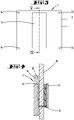
- the cabinet door lock S of the invention has a housing 1 made of plastic, for example, which can be mounted on the inside of a cabinet door 10 of a cabinet facing the interior of a cabinet.
- the housing 1 is fastened to the cabinet door 10 by means of screws 15 which can be screwed into the door leaf through screw-on openings 14 in the housing 1 .
- the screw-on openings 14 are located at the corners of a rectangle.
- a bolt 2 is located inside the housing 1.
- the bolt 2 has such a length that it can be brought from a first operating position, in which a bolt head protrudes on the left side of the lock, into a second operating position by actuating an actuating unit 4. in which a bolt head protrudes from the right side of the lock.
- the length of the bar can be greater than the distance between two opposite edges of the housing.
- the left end of the bolt 2 is shown in its locked position.
- the right end of the bolt 2 takes an open position.
- An actuating unit which can be a motor 4 or a manually rotatable handle, acts on the bolt 2 in such a way that actuation of the actuating unit moves the bolt from the in figure 1 shown in the first position in the figure 2 shown second position and can shift back to the first operating position.
- an eccentric pin 3 can engage in a transverse slot of the bolt 2 .
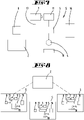
- the housing 1 has a battery compartment 6.
- One or more, preferably three, batteries 7 can be arranged in the battery compartment 6.
- the batteries serve to supply energy to the cabinet door lock S. All electrical and electronic consumers of the cabinet door lock S are preferably supplied with power by the batteries 7 .
- An electronic circuit 5 is located inside the housing.
- the electronic circuit 5 interacts with the electric motor 4 , an access control device 16 , a code input device 11 and a radio module 8 .
- the radio module 8 contains a transmitter/receiver device in order to transmit data, in particular locking status data, to a central unit Z.
- the code input device 11 can be a communication module which can be accommodated in a compartment 9 of the housing 1 . Over a The communication module 11 is connected to the electronic circuit 5 by cable connection 17 .
- the access control device 16 can be a physical part of the electronic circuit. This can be a microcontroller arrangement that is able to check an opening code for locking authorization.
- the figure 4 shows a first installation variant of the cabinet door lock S.
- the housing 1 is on the inside of a cabinet door.
- the communication module 11 is located on the outside of the cabinet door and can be used as a handle.
- the communication module 11 is connected to the electronic circuit 5 via the cable 17 which passes through an opening in the door leaf 10 .
- the figure 6 shows, the communication module 11 is in a receiving pocket 9, which is located on the screw-on side of the housing.
- the communication module has a keypad consisting of several keys 12 for typing in an opening code. It also has an antenna arrangement 13 with which data transmission communication can be carried out with an RFID device, a transponder, in order to read out the digital identifier of the transponder after the communication module 11 has detected that a transponder has approached.
- the access control device 16 checks whether the entered PIN or the transponder identifier has locking authorization. Typing in a code or recognizing the approach of a transponder leads to activation of the electronic circuit 5 so that a data set is sent to the central unit Z via the radio module 8 . Following this, the transceiver has the radio module 8 for a short time a readiness to receive and is able to receive control data or the like from the central unit Z.
- the transceiver 8 transmits the PIN or the transponder identifier to the central unit Z and the latter sends the transceiver 8 a locking or an opening command, so that only after the locking authorization has been checked by the central unit of the bolt can be advanced or reversed.
- the S cabinet lock works independently and checks the locking authorization itself.
- Reference number 18 symbolizes sensors or sensor elements with which specific operating states of the cabinet lock or cabinet can be detected. With these sensors or sensor elements 18, for example, the proper functioning of the cabinet door lock S can be checked. It is also possible to use these sensors or sensor elements 18 to determine whether manipulation attempts are being made to the cabinet door lock, so that the transceiver 8 transmits an alarm signal to the central device Z in such a case. It is thus possible to react to vandalism and disturbances. It is also possible to open or close the cabinet door lock remotely, for example to react to the loss of a transponder key or a PIN. In this case, activating the electronic circuit by entering any PIN or by approaching any transponder to the communication module 11 is sufficient to move the bolt 2 .
- the figure 8 shows a block diagram of an arrangement such as is found in a swimming pool, for example.
- Each of the cabinet door locks S communicates with the central unit Z, so with a central unit Z via a wireless Communication link can manage a variety of self-sufficiently working cabinet locks S without having to lead power supply lines to the individual cabinet door locks or between cabinet door lock S and central unit Z a data transmission line must be present.
- the cabinet door lock S works with minimal energy consumption.
- the electronic circuit 5 can have a clock which causes the communication module 11 to generate a low-power transponder detection signal at regular intervals, which only establishes a transponder detection field in the area immediately around the communication module 11 . Only when a transponder is detected within the transponder detection field is the electronic circuit for data communication with the transponder activated or does the transceiver 8 send locking status data to the central unit Z and goes into a receiving mode for a specified time in which it is able to receive data from the central unit Z. Otherwise the transceiver is in an idle state. The batteries therefore have a very long service life.
Description
Die Erfindung betrifft ein Schranktürschloss mit einem auf der zum Innenraum des Schrankes weisenden Innenseite einer Schranktür insbesondere im Austausch gegen ein dort vorhandenes Schrankschloss befestigbaren Gehäuse mit einer Batterieaufnahme zur Aufnahme einer Batterie zur Energieversorgung einer elektronischen Einrichtung des Schranktürschlosses, wobei die elektronische Einrichtung des Schranktürschlosses eine Codeeingabeeinrichtung aufweist, mit der ein Öffnungscode eingegeben werden kann, sodass bei einem eine Schließberechtigung aufweisenden Öffnungscode ein Riegel zwischen zwei Riegelstellungen hin und her verlagerbar ist, wobei eine Riegelstellung eine Öffnungsstellung, in der die Schranktür geöffnet werden kann und die andere Riegelstellung eine Verriegelungsstellung ist, in der die Schranktür nicht geöffnet werden kann, weil der Riegel in eine dem Korpus des Schrankes zugeordnete Riegeleintrittsöffnung eingefahren ist. Eine Sende-/Empfangseinrichtung ist in der Lage, mit einer Zentraleinheit drahtlos zu kommunizieren, um Schließdaten zu übertragen.The invention relates to a cabinet door lock with a housing that can be fastened on the inside of a cabinet door facing the interior of the cabinet, in particular in exchange for a cabinet lock that is present there, with a battery holder for accommodating a battery for supplying energy to an electronic device of the cabinet door lock, the electronic device of the cabinet door lock having a code input device with which an opening code can be entered, so that with an opening code having locking authorization, a bolt can be moved back and forth between two bolt positions, one bolt position being an open position in which the cabinet door can be opened and the other bolt position being a locked position, in which the cabinet door cannot be opened because the bolt has entered a bolt entry opening associated with the body of the cabinet. A transceiver is able to communicate wirelessly with a central unit in order to transmit locking data.
Aus der
Die
Ein ähnliches Schranktürschloss beschreibt die
Die
Die
Die
Der Erfindung liegt die Aufgabe zugrunde, ein Schranktürschloss anzugeben, welches gegen ein händisch zu betätigendes Schranktürschloss austauschbar ist und eine verbesserte Funktionalität aufweist.The invention is based on the object of specifying a cabinet door lock which can be exchanged for a manually operated cabinet door lock and which has improved functionality.
Gelöst wird die Aufgabe durch die in den Ansprüchen angegebene Erfindung.The object is achieved by the invention specified in the claims.
In ihrer Gesamtheit besitzt das Schranktürschloss die nachfolgend aufgeführten konstruktiven und funktionellen Merkmale. Das Schranktürschloss besitzt ein Gehäuse. Das Gehäuse ist auf der zum Innenraum eines Schrankes weisenden Innenseite an einer Schranktür befestigbar. Es kann insbesondere gegen ein bereits dort vorhandenes Schrankschloss, welches nicht die technisch weiterbildenden Merkmale der Erfindung aufweist, ausgetauscht werden. Das Gehäuse beinhaltet einen Motor, der von einer elektronischen Schaltung angesteuert werden kann, oder eine Handhabe, die mit einem Riegelantrieb gekuppelt werden kann. Die elektronische Schaltung wirkt mit einer Codeeingabeeinrichtung zusammen. Über die Codeeingabeeinrichtung kann ein Öffnungscode eingegeben werden. Dies kann über eine Tastatur erfolgen. Die Codeeingabe kann aber auch durch in die Nähe halten eines Transponders erfolgen. Die Codeeingabeeinrichtung besitzt hierzu eine Kommunikationseinrichtung, die mit dem Transponder drahtlos kommuniziert. An den Transponder wird ein drahtloses Aufwecksignal gesendet, sodass der Transponder seine individuelle Kennung an die Codeeingabeeinrichtung sendet. Die Codeeingabeeinrichtung kann permanent oder intervallartig ein Prüfsignal erzeugen, welches ein elektromagnetisches Detektorfeld aufbaut, um zu prüfen, ob sich ein Transponder unmittelbar in der Nähe des Schranktürschlosses befindet. Dieses Signal wird mit sehr geringer Leistung erzeugt, sodass es keine Fernwirkung besitzt. Erst wenn das Vorhandensein eines Transponders in der unmittelbaren Nähe der Codeeingabeeinrichtung erfasst wird, wird ein leistungsstärkeres Aufwecksignal erzeugt, das den Transponder veranlasst, seine Kennung zu senden. Die Codeeingabeeinrichtung oder die elektronische Schaltung besitzen eine Schließberechtigungsprüfeinrichtung, mit der geprüft wird, ob der über die Tastatur oder die Transponder-Leseeinrichtung empfangene Öffnungscode eine Schließberechtigung besitzt. Diese Prüfung erfolgt aufgrund einer Aktivierung der elektronischen Schaltung, die entweder durch die PIN-Eingabe oder das Auslesen der Kennung eines Transponders erfolgt. Wird die Schließberechtigung des Öffnungscodes festgestellt, also bei einer schließberechtigten Aktivierung der elektronischen Schaltung, kann mit einem Betätigungsaggregat der Riegel zwischen zwei Riegelstellungen hin und her verlagert werden. Hierzu kann es vorgesehen sein, dass der Motor in Betrieb gesetzt, um den Riegel, der zwischen zwei Riegelstellungen hin und her verlagerbar ist, in die jeweils andere Riegelstellung zu verlagern. Es ist aber auch vorgesehen, dass eine Kupplung, die eine Betätigungshandhabe mit einem Riegelantrieb kuppelt von einer entkuppelten Stellung in eine gekuppelten Stellung gebracht wird, in der die Betätigung den Riegel verlagert. Der Riegel wird somit entweder in eine Öffnungsstellung gebracht, in der die Schranktür geöffnet werden kann, oder in eine Verriegelungsstellung, in der die Schranktür nicht geöffnet werden kann. Es ist eine Sende-Empfangseinrichtung vorgesehen, die von der optionalen Transponder-Leseeinrichtung funktionell getrennt ist. Diese, mit der elektronischen Schaltung zusammenwirkende Sende-Empfangseinrichtung dient zur drahtlosen Datenübertragung von zumindest Schließzustandsdaten an eine Zentraleinheit. Es ist vorgesehen, dass bei jeder Aktivierung der elektronischen Schaltung Schließzustandsdaten an die Zentraleinheit übertragen werden. Die Schließzustandsdaten beinhalten zumindest den Schließzustand des Schlosses vor bzw. nach der Codeeingabe und /oder den eingegebenen Code, also den PIN oder die individuelle Transponderkennung. Mit der Zentraleinheit können somit eine Vielzahl von Schranktürschlössern eine Anordnung, die eine Vielzahl von Schränken beinhaltet, verwaltet werden. Die Schranktürschlossverwaltung erfolgt als Folge der drahtlosen Datenfernübertragung ohne die Notwendigkeit von Leitungen, insbesondere von Busleitungen. Das Gehäuse besitzt eine Batterieaufnahme. Die Batterieaufnahme kann in demselben Gehäuse angeordnet sein, die auch den Riegel beinhaltet. Das Gehäuse kann aber auch aus mehreren, voneinander räumlich getrennten Einzelgehäusen ausgebildet sein, wobei die Batterie in einem vom Riegel getrennten Gehäuse angeordnet sein kann. Die Batterie dient insbesondere zur Energieversorgung des Motors oder der Kupplung, der elektronischen Schaltung, der Codeeingabeeinrichtung und der Sende-Empfangseinrichtung. Bevorzugt sind sämtliche elektrischen oder elektronischen Aggregate des Schranktürschlosses batteriebetrieben, sodass das Schranktürschloss keine Kabelverbindung mit einer externen Energieversorgung benötigt. Es handelt sich somit um ein autarkes Schloss, welches eine lange Betriebszeit besitzen kann, da es vorgesehen ist, dass die Sende-Empfangseinrichtung überwiegend ihren Ruhezustand einnimmt. Es ist vorgesehen, dass die Sende-Empfangseinrichtung nur nach einem vorgegebenen Zeitintervall ein Lebenszeichen an die Zentraleinheit sendet und ansonsten nur dann Schließzustandsdaten an die Zentraleinheit übermittelt, wenn die elektronische Schaltung aktiviert wird. Die Sende-Empfangseinrichtung geht nur dann in eine Empfangsbereitschaft, wenn sie zuvor aktiviert worden ist oder das zyklische Lebenszeichen abgesandt hat, wobei es ausreicht, wenn die Sende-Empfangseinrichtung einmal täglich ein diesbezügliches Lebenszeichen absendet. Dies minimiert den Energieverbrauch. Die elektronische Schaltung beinhaltet eine Uhr, die einen Takt vorgibt, nach dem ein Transponder-Erkennungssignal mit schwacher Leistung aufgebaut wird, um die Anwesenheit eines Transponders zu ermitteln, und das Lebenszeichen an die Zentraleinheit abgesandt wird. Funktionen mit einem größeren Energieverbrauch werden nur individuell nach einer Aktivierung vorgenommen. Anstelle einer drahtlosen Erfassung der Annäherung eines Transponders ist es aber auch möglich, einen Schalter vorzusehen, der bspw. durch Anlage des Transponders betätigt werden muss, um die Datenkommunikation mit dem Transponder zu starten. Die Codeeingabeeinrichtung kann als modulares Kommunikationsmodul ausgebildet sein. Dieses Kommunikationsmodul kann in einem Aufnahmefach des Gehäuses angeordnet sein. Das Kommunikationsmodul kann sich somit auf der Schrankinnenseite befinden. Bei dieser Anordnung ist die elektronische Schaltung nur durch die Annäherung eines Transponders aktivierbar. Die drahtlose Kommunikation mit dem Transponder erfolgt dann durch die insbesondere aus Holz bestehende Schranktür hindurch. Das Kommunikationsmodul kann aber auch auf der Türaußenseite montiert sein. Es ist dann über ein Kabel mit der elektronischen Schaltung verbunden. Bevorzugt steckt ein am Ende des Kabels befestigter Stecker in einer Einsteckbuchse der elektronischen Schaltung. Das Kommunikationsmodul kann als Türgriff verwendet werden. Das Schranktürschloss kann sowohl an links angeschlagenen als auch an rechts angeschlagenen Schranktürflügeln verwendet werden. Hierzu besitzt das Schranktürschloss einen Riegel, der bevorzugt länger ist, als die Breite des Schlosses und der mittels des Motors in Breitenerstreckungsrichtung hin und her fahrbar ist, sodass jeweils ein Ende des Riegels über das Gehäuse hinausragt. In einer ersten Betriebsstellung ragt ein erstes Ende des Riegels über eine erste Gehäuseseite. In einer zweiten Betriebsstellung des Riegels ragt ein zweites Ende des Riegels, das dem ersten Ende gegenüberliegt über eine zweite Gehäuseseite, die der ersten Gehäuseseite gegenüberliegt. Das Gehäuse besitzt Anschrauböffnungen, die entsprechend einem Lochbild angeordnet sind, das ein Schloss, wie es aus der eingangs genannten
Im Folgenden wird die Erfindung anhand von Ausführungsbeispielen näher erläutert. Es zeigen:
- Fig. 1
- Eine Draufsicht in das Gehäuse eines Schranktürschlosses in einer ersten Riegelstellung, in der der Riegel auf der linken Seite vorgeschlossen und auf der rechten Seite zurückgeschlossen ist,
- Fig. 2
- eine zweite Betriebsstellung des Schlosses in einer Darstellung gemäß
Figur 1 , wobei der Riegel auf der linken Seite zurückgeschlossen und auf der rechten Seite vorgeschlossen ist, - Fig. 3
- eine Rückseitenansicht des Schlosses,
- Fig. 4
- den Schnitt gemäß der Linie IV-IV in
Figur 3 - Fig. 5
- ein Kommunikationsmodul in der Draufsicht,
- Fig. 6
- den Schnitt gemäß der Linie IV-
IV gemäß Figur 3 jedoch mit in der Aufnahmekammer angeordnetem Kommunikationsmodul, - Fig. 7
- ein Blockschaltbild der Funktionselemente des Schrankschlosses und
- Fig. 8
- als Blockschaltbild das Zusammenwirken einer Vielzahl von Schranktürschlössern einer Schrankanordnung mit einer Zentraleinheit.
- 1
- A plan view of the housing of a cabinet door lock in a first bolt position, in which the bolt is pre-locked on the left side and closed on the right side,
- 2
- a second operating position of the castle in a representation according to
figure 1 , with the latch closed on the left side and closed on the right side, - 3
- a rear view of the castle,
- 4
- the cut according to line IV-IV in
figure 3 , - figure 5
- a communication module in plan view,
- 6
- cut according to line IV-IV
figure 3 but with the communication module arranged in the receiving chamber, - 7
- a block diagram of the functional elements of the cabinet lock and
- 8
- as a block diagram the interaction of a large number of cabinet door locks in a cabinet arrangement with a central unit.
Das Schranktürschloss S der Erfindung besitzt ein bspw. aus Kunststoff gefertigtes Gehäuse 1, welches auf der zum Innenraum eines Schrankes weisenden Innenseite einer Schranktür 10 eines Schrankes montierbar ist. Die Befestigung des Gehäuses 1 an der Schranktür 10 erfolgt mittels Schrauben 15, die durch Anschrauböffnungen 14 des Gehäuses 1 hindurch in das Türblatt eingeschraubt werden können. Die Anschrauböffnungen 14 befinden sich auf den Eckpunkten eines Rechtecks.The cabinet door lock S of the invention has a
Innerhalb des Gehäuses 1 befindet sich ein Riegel 2. Beim Ausführungsbeispiel besitzt der Riegel 2 eine derartige Länge, dass er durch Betätigen eines Betätigungsaggregates 4 von einer ersten Betriebsstellung, in der ein Riegelkopf auf der linken Seite des Schlosses herausragt in eine zweite Betriebsstellung bringbar ist, in der ein Riegelkopf aus der rechten Schlossseite herausragt. Die Länge des Riegels kann dabei größer sein als der Abstand zweier gegenüberliegender Randkanten des Gehäuses. In der
Das Gehäuse 1 besitzt ein Batterieaufnahmefach 6. In dem Batterieaufnahmefach 6 können ein oder mehrere, bevorzugt drei Batterien 7 angeordnet sein. Die Batterien dienen der Energieversorgung des Schranktürschlosses S. Bevorzugt werden sämtliche elektrischen und elektronischen Verbraucher des Schranktürschlosses S durch die Batterien 7 leistungsversorgt.The
Innerhalb des Gehäuses befindet sich eine elektronische Schaltung 5. Die elektronische Schaltung 5 wirkt mit dem Elektromotor 4, einer Zugangskontrolleinrichtung 16, einer Codeeingabeeinrichtung 11 und einem Funkmodul 8 zusammen. Das Funkmodul 8 beinhaltet eine Sende-/Empfangseinrichtung, um Daten, insbesondere Schließzustandsdaten an eine Zentraleinheit Z zu übermitteln. Die Codeeingabeeinrichtung 11 kann ein Kommunikationsmodul sein, welches in einem Fach 9 des Gehäuses 1 Aufnahme finden kann. Über eine Kabelverbindung 17 ist das Kommunikationsmodul 11 mit der elektronischen Schaltung 5 verbunden. Die Zugangskontrolleinrichtung 16 kann körperlicher Teil der elektronischen Schaltung sein. Es kann sich hierbei um eine Mikrokontrolleranordnung handeln, die in der Lage ist, einen Öffnungscode auf Schließberechtigung zu überprüfen.An
Die
In einer zweiten Einbauvariante, die die
Das Kommunikationsmodul besitzt ein aus mehreren Tasten 12 bestehendes Tastenfeld, um einen Öffnungscode einzutippen. Es besitzt darüber hinaus eine Antennenanordnung 13, mit der eine Datenübertragungskommunikation mit einer RFID-Einrichtung, einem Transponder durchgeführt werden kann, um nach der Erkennung einer Annäherung eines Transponders an das Kommunikationsmodul 11 die digitale Kennung des Transponders auszulesen. Die Zugangskontrolleinrichtung 16 prüft dann, ob der eingegebene PIN oder die Transponderkennung eine Schließberechtigung aufweist. Das Eintippen eines Codes oder das Erkennen der Annäherung eines Transponders führt zu einer Aktivierung der elektronischen Schaltung 5, sodass über das Funkmodul 8 ein Datensatz an die Zentraleinheit Z gesandt wird. Im Anschluss daran besitzt die Sende-Empfangseinrichtung des Funkmoduls 8 für eine kurze Zeit eine Empfangsbereitschaft und ist in der Lage, Steuerungsdaten oder dergleichen von der Zentraleinheit Z zu empfangen. Bspw. kann es vorgesehen sein, dass die Sende-Empfangseinrichtung 8 den PIN oder die Transponderkennung an die Zentraleinheit Z übermittelt und letztere der Sende-Empfangseinrichtung 8 einen Schließ- oder einen Öffnungsbefehl schickt, sodass nur nach einer Überprüfung der Schließberechtigung durch die Zentraleinheit der Riegel vor- oder zurückgeschlossen werden kann. Es ist aber auch vorgesehen, dass das Schrankschloss S autark arbeitet und die Schließberechtigung selbst überprüft.The communication module has a keypad consisting of
Die Bezugsziffer 18 symbolisiert Sensoren oder Sensorelemente, mit denen bestimmte Betriebszustände des Schrankschlosses oder Schranks erfasst werden können. Mit diesen Sensoren oder Sensorelementen 18 kann bspw. das ordnungsgemäße Funktionieren des Schranktürschlosses S überprüft werden. Es ist ferner möglich, mit diesen Sensoren oder Sensorelementen 18 festzustellen, ob am Schranktürschloss Manipulationsversuche vorgenommen werden, sodass in einem derartigen Fall die Sende-Empfangseinrichtung 8 ein Alarmsignal an die Zentraleinrichtung Z übermittelt. Es kann somit auf Vandalismus und auf Störungen reagiert werden. Ferner ist es möglich, dass Schranktürschloss ferngesteuert zu öffnen oder zu schließen, bspw. um auf den Verlust eines Transponderschlüssels oder einer PIN zu reagieren. In diesem Falle reicht bereits eine Aktivierung der elektronischen Schaltung, durch Eingaben eines beliebigen PIN's oder durch Annähern eines beliebigen Transponders an das Kommunikationsmodul 11 aus, um den Riegel 2 zu verlagern.
Die
Das Schranktürschloss S arbeitet mit einem minimalen Energieaufwand. Die elektronische Schaltung 5 kann eine Uhr aufweisen, die in regelmäßigen Abständen veranlasst, dass das Kommunikationsmodul 11 mit schwacher Leistung ein Transpondererfassungssignal erzeugt, welches nur im Bereich unmittelbar um das Kommunikationsmodul 11 ein Transpondererfassungsfeld aufbaut. Nur wenn innerhalb des Transpondererfassungsfeldes ein Transponder erfasst wird, wird die elektronische Schaltung zur Datenkommunikation mit dem Transponder aktiviert bzw. sendet die Sende-Empfangseinrichtung 8 Schließzustandsdaten an die Zentraleinheit Z und geht für eine vorgegebene Zeit in einen Empfangsmodus, in dem sie in der Lage ist, Daten von der Zentraleinheit Z zu empfangen. Ansonsten befindet sich die Sende-Empfangseinrichtung in einem Ruhezustand. Die Batterien haben somit eine sehr lange Standzeit.The cabinet door lock S works with minimal energy consumption. The
- 11
- GehäuseHousing
- 22
- Riegelbars
- 33
- Exzenterzapfeneccentric pin
- 44
- Motorengine
- 55
- Elektronische SchaltungElectronic switch
- 66
- Batteriefachbattery compartment
- 77
- Batteriebattery
- 88th
- Funkmodul (Sende-/ EmpfangseinrichtungRadio module (transmitting/receiving device
- 99
- Aufnahmefachreceiving compartment
- 1010
- Schranktürcloset door
- 1111
- Kommunikationsmodulcommunication module
- 1212
- TastenKeys
- 1313
- Antennenanordnungantenna arrangement
- 1414
- Anschrauböffnungscrew opening
- 1515
- Schraubescrew
- 1616
- Zugangskontrolleinrichtungaccess control device
- 1717
- Verbindungskabelconnection cable
- 1818
- Sensorelementsensor element
- SS
- Schranktürschlosscabinet door lock
- ZZ
- Zentraleinheitcentral unit
Claims (11)
- A cabinet door lock (S) with a housing (1) that can be fastened on a cabinet door (10), particularly in exchange for a cabinet door lock installed thereon, wherein an actuating unit (4), an electronic circuit (5) interacting with a code input device (11), a bolt (2), which after authorized activation of the electronic circuit (5) can be displaced back and forth between two bolt positions by the actuating unit (4), and a transmitting/receiving device (8), which interacts with the electronic circuit and serves for the wireless data transmission of at least closing state data to a central unit (Z), are arranged in said housing, and with a battery receptacle (6) for accommodating a battery (7) for the power supply of the actuating unit (4), the electronic circuit (5), the code input device (11) and the transmitting/receiving device (8), wherein the cabinet door lock is designed in such a way that an input of a code into a keypad of the code input device (11) or an approach of a transponder to the code input device (11) leads to an activation of the electronic circuit, characterized in that the transmitting/receiving device is designed in such a way that it transmits closing state data to the central unit upon each activation of the electronic circuit (5), and in that the receiving device (8) is designed in such a way that it switches into a receiving mode for a predetermined time after the transmission of the closing state data, but only after the transmission of a sign of life to the central unit, after the input of the code into the keypad or the detection of the approach of the transponder, in order to receive data from the central unit (Z) and otherwise is in a sleep mode.
- The cabinet door lock according to claim 1, characterized in that the actuating unit is a motor (4), which is activated by the electronic circuit (5), or a coupling for coupling an actuating handle to the bolt (2).
- The cabinet door lock according to one of the preceding claims, characterized in that the code input device (11) is realized in the form of a communication module and can be plug-connected to the electronic circuit (5) via a connecting cable (17), as well as used as a door handle.
- The cabinet door lock according to claim 2, characterized in that the code input device (11) has keys (12) and/or a transponder communication device (13) .
- The cabinet door lock according to one of the preceding claims, characterized in that the closing state data contains the functional position of the bolt (2) and/or an individual identifier of a transponder.
- The cabinet door lock according to one of the preceding claims, characterized in that the data, which is wirelessly transmitted from the central unit (Z) to the transmitting/receiving device (8), contains an opening or closing command for the bolt (2).
- The cabinet door lock according to one of the preceding claims, characterized in that the power supply of the cabinet door lock is exclusively realized with one or more batteries (7) accommodated in the battery receptacle (11).
- The cabinet door lock according to one of the preceding claims, characterized in that the cabinet door lock can be used on left-closing doors and on right-closing doors, wherein the bolt (2) is to this end moved out of a first side of the housing in a first bolt position and moved out of a second side of the housing (1) lying opposite of the first side in a second bolt position.
- The cabinet door lock according to one of the preceding claims, characterized in that the housing (1) has four screw-on openings (14) that are arranged on the corners of a rectangle, wherein the housing (1) can be fastened on the inner side of the cabinet door facing the interior of the cabinet with the aid of said screw-on openings.
- A cabinet arrangement with a plurality of cabinets, which respectively have a door and a cabinet door lock (S) according to one of the preceding claims, and with a central unit (Z), which is designed in such a way that it can wirelessly receive at least closing state data from each of the cabinet door locks (S) and, after the reception of closing state data, can wirelessly transmit an opening or closing command to the cabinet lock (S) such that the bolt (2) can be displaced into an open position or a locking position.
- The cabinet door lock according to one of claims 1 to 9 or a cabinet arrangement according to claim 10, characterized in that sensors or sensor elements (18) are provided and make it possible to check the proper function of the cabinet lock (3), wherein the electronic circuit (5) is designed in such a way that an alarm signal is transmitted to the central unit when manipulation attempts are detected on the cabinet door lock by the sensors or sensor elements (18).
Applications Claiming Priority (1)
| Application Number | Priority Date | Filing Date | Title |
|---|---|---|---|
| DE102015113243.5A DE102015113243B4 (en) | 2015-08-11 | 2015-08-11 | Cabinet door lock that communicates wirelessly with a central unit |
Publications (2)
| Publication Number | Publication Date |
|---|---|
| EP3131068A1 EP3131068A1 (en) | 2017-02-15 |
| EP3131068B1 true EP3131068B1 (en) | 2022-09-07 |
Family
ID=56567484
Family Applications (1)
| Application Number | Title | Priority Date | Filing Date |
|---|---|---|---|
| EP16182377.8A Active EP3131068B1 (en) | 2015-08-11 | 2016-08-02 | Cabinet door lock communicating wirelessly with a central unit |
Country Status (2)
| Country | Link |
|---|---|
| EP (1) | EP3131068B1 (en) |
| DE (1) | DE102015113243B4 (en) |
Families Citing this family (1)
| Publication number | Priority date | Publication date | Assignee | Title |
|---|---|---|---|---|
| DE102020216345A1 (en) | 2020-12-18 | 2022-06-23 | Smart Access Solutions Gmbh | Electronic lock device, in particular a key safe, and method for operating the electric lock device |
Citations (33)
| Publication number | Priority date | Publication date | Assignee | Title |
|---|---|---|---|---|
| US1591010A (en) | 1923-07-10 | 1926-07-06 | Frank E Best Inc | Lock |
| EP0785325A1 (en) | 1996-01-20 | 1997-07-23 | DIEHL GMBH & CO. | Lock activated by an identity carrier |
| US5886644A (en) | 1996-03-12 | 1999-03-23 | Security People, Inc. | Programmable digital electronic lock |
| DE19832203A1 (en) | 1998-07-17 | 2000-01-20 | Kostal Leopold Gmbh & Co Kg | Activating electrically operated, current-consuming component through code word contained in data message of predetermined format |
| DE19832516A1 (en) | 1998-07-20 | 2000-01-27 | Schulte Schlagbaum Ag | Lock, especially for a locking system |
| WO2001042594A2 (en) | 1999-12-08 | 2001-06-14 | Winfield Locks, Inc. D.B.A. Computerized Security Systems | Electronic lock |
| EP1338735A1 (en) | 2002-02-25 | 2003-08-27 | DOM-Sicherheitstechnik GmbH & Co. KG | System, arrangement and method to control access |
| US6720861B1 (en) | 1999-03-12 | 2004-04-13 | Best Access Systems | Wireless security control system |
| US6791450B2 (en) | 2001-07-31 | 2004-09-14 | Security People, Inc. | Networked digital locker lock system |
| DE10329969A1 (en) | 2003-07-03 | 2005-01-20 | Mehmet Sancak | Battery supported lock for doors of flats, rooms, houses, cabinets etc. containing access control circuit, normally in sleeping mode, not consuming any current, activated by energizer |
| WO2005054609A1 (en) | 2003-12-08 | 2005-06-16 | Abloy Oy | Locking system and method for locking system |
| US20050212656A1 (en) | 1994-11-15 | 2005-09-29 | Micro Enhanced Technology, Inc. | Electronic access control device |
| DE102004056987A1 (en) | 2004-11-25 | 2006-06-01 | Keyowa Gmbh | Security lock with wireless release has an integral receiver and transmitters and with a coded release for a clutch to connect the door handle to the lock |
| EP1818874A1 (en) * | 2005-10-05 | 2007-08-15 | Insafe International Limited | Remote monitoring system for a security lock |
| WO2008048933A2 (en) | 2006-10-16 | 2008-04-24 | Assa Abloy Hospitality, Inc. | Centralized wireless network for multi-room large properties |
| DE102006058723A1 (en) | 2006-12-13 | 2008-06-19 | Dr.Ing.H.C. F. Porsche Ag | Method for realizing a keyless entry of at least one vehicle door |
| EP2031566A1 (en) | 2007-09-03 | 2009-03-04 | Burg-Wächter Kg | Method for operating a system with at least one electronic lock |
| EP2050902A1 (en) | 2007-10-18 | 2009-04-22 | USM Holding AG | Mechatronic furniture lock |
| DE102007052583A1 (en) | 2007-10-29 | 2009-04-30 | Schulte-Schlagbaum Ag | Münzpfandschrankverschluss |
| WO2010032091A1 (en) | 2008-09-19 | 2010-03-25 | Freescale Semiconductor, Inc. | Wake-up control system and method for controlling receiver wake-up |
| WO2010144449A1 (en) | 2009-06-08 | 2010-12-16 | Harrow Products Llc | Electronic door lock for reduced power consumption |
| US20110012709A1 (en) | 2009-07-14 | 2011-01-20 | Compx International Inc. | Method and system for data control in electronic locks |
| US20110025459A1 (en) | 1994-11-15 | 2011-02-03 | Denison William D | Electronic Access Control Device and Management System |
| US20110050391A1 (en) | 1994-11-15 | 2011-03-03 | Denison William D | Electronic Access Control Device and Management System |
| US20110187496A1 (en) | 2008-10-30 | 2011-08-04 | Denison William D | Electronic Access Control Device and Management System |
| US20110210818A1 (en) | 1994-11-15 | 2011-09-01 | Denison William D | Electronic Access Control Device and Management System |
| US20120011367A1 (en) | 2005-04-21 | 2012-01-12 | Denison William D | Method for Controlling and Recording the Security of an Enclosure |
| DE202012001226U1 (en) | 2012-01-25 | 2012-08-10 | Teratron Gmbh | System for controlling access authorization for lockable objects |
| US20140020437A1 (en) | 2005-03-18 | 2014-01-23 | Phoniro Ab | Lock actuating device and an access control system |
| DE102012017820A1 (en) | 2012-09-08 | 2014-03-13 | Gantner Electronic Gmbh | Method for operating cabinet lock i.e. wireless cabinet lock, of centrally closure system, involves converting mechanical energy into electrical power by operation of cabinet lock, and exploiting close-side control for electrical supply |
| DE102012018323A1 (en) | 2012-09-15 | 2014-03-20 | Gantner Electronic Gmbh | Method for updating cabinet-side software of electronic cabinet lock of multi-cabinet system, involves communicating locks with server, and carrying out updation of software of locks by wireless or equivalent transmission path from server |
| DE102014105245A1 (en) | 2013-12-05 | 2015-06-11 | Deutsche Post Ag | A method for effecting a change of an operating mode |
| DE102015110139A1 (en) | 2015-06-24 | 2016-12-29 | Emka Beschlagteile Gmbh & Co. Kg | Access control system for a variety of closures |
Family Cites Families (1)
| Publication number | Priority date | Publication date | Assignee | Title |
|---|---|---|---|---|
| DE102012216816B3 (en) | 2012-09-19 | 2014-05-28 | Carl H. Scheuermann | Lock cylinder for castle, has frequency-selective switch separating DC and data signals, and transmitter and receiver transmitting and receiving data signals, where receiver is activated by data signal |
-
2015
- 2015-08-11 DE DE102015113243.5A patent/DE102015113243B4/en active Active
-
2016
- 2016-08-02 EP EP16182377.8A patent/EP3131068B1/en active Active
Patent Citations (34)
| Publication number | Priority date | Publication date | Assignee | Title |
|---|---|---|---|---|
| US1591010A (en) | 1923-07-10 | 1926-07-06 | Frank E Best Inc | Lock |
| US7741952B2 (en) | 1994-11-15 | 2010-06-22 | Micro Enhanced Technology, Inc. | Electronic access control device |
| US20110210818A1 (en) | 1994-11-15 | 2011-09-01 | Denison William D | Electronic Access Control Device and Management System |
| US20110050391A1 (en) | 1994-11-15 | 2011-03-03 | Denison William D | Electronic Access Control Device and Management System |
| US20110025459A1 (en) | 1994-11-15 | 2011-02-03 | Denison William D | Electronic Access Control Device and Management System |
| US20050212656A1 (en) | 1994-11-15 | 2005-09-29 | Micro Enhanced Technology, Inc. | Electronic access control device |
| EP0785325A1 (en) | 1996-01-20 | 1997-07-23 | DIEHL GMBH & CO. | Lock activated by an identity carrier |
| US5886644A (en) | 1996-03-12 | 1999-03-23 | Security People, Inc. | Programmable digital electronic lock |
| DE19832203A1 (en) | 1998-07-17 | 2000-01-20 | Kostal Leopold Gmbh & Co Kg | Activating electrically operated, current-consuming component through code word contained in data message of predetermined format |
| DE19832516A1 (en) | 1998-07-20 | 2000-01-27 | Schulte Schlagbaum Ag | Lock, especially for a locking system |
| US6720861B1 (en) | 1999-03-12 | 2004-04-13 | Best Access Systems | Wireless security control system |
| WO2001042594A2 (en) | 1999-12-08 | 2001-06-14 | Winfield Locks, Inc. D.B.A. Computerized Security Systems | Electronic lock |
| US6791450B2 (en) | 2001-07-31 | 2004-09-14 | Security People, Inc. | Networked digital locker lock system |
| EP1338735A1 (en) | 2002-02-25 | 2003-08-27 | DOM-Sicherheitstechnik GmbH & Co. KG | System, arrangement and method to control access |
| DE10329969A1 (en) | 2003-07-03 | 2005-01-20 | Mehmet Sancak | Battery supported lock for doors of flats, rooms, houses, cabinets etc. containing access control circuit, normally in sleeping mode, not consuming any current, activated by energizer |
| WO2005054609A1 (en) | 2003-12-08 | 2005-06-16 | Abloy Oy | Locking system and method for locking system |
| DE102004056987A1 (en) | 2004-11-25 | 2006-06-01 | Keyowa Gmbh | Security lock with wireless release has an integral receiver and transmitters and with a coded release for a clutch to connect the door handle to the lock |
| US20140020437A1 (en) | 2005-03-18 | 2014-01-23 | Phoniro Ab | Lock actuating device and an access control system |
| US20120011367A1 (en) | 2005-04-21 | 2012-01-12 | Denison William D | Method for Controlling and Recording the Security of an Enclosure |
| EP1818874A1 (en) * | 2005-10-05 | 2007-08-15 | Insafe International Limited | Remote monitoring system for a security lock |
| WO2008048933A2 (en) | 2006-10-16 | 2008-04-24 | Assa Abloy Hospitality, Inc. | Centralized wireless network for multi-room large properties |
| DE102006058723A1 (en) | 2006-12-13 | 2008-06-19 | Dr.Ing.H.C. F. Porsche Ag | Method for realizing a keyless entry of at least one vehicle door |
| EP2031566A1 (en) | 2007-09-03 | 2009-03-04 | Burg-Wächter Kg | Method for operating a system with at least one electronic lock |
| EP2050902A1 (en) | 2007-10-18 | 2009-04-22 | USM Holding AG | Mechatronic furniture lock |
| DE102007052583A1 (en) | 2007-10-29 | 2009-04-30 | Schulte-Schlagbaum Ag | Münzpfandschrankverschluss |
| WO2010032091A1 (en) | 2008-09-19 | 2010-03-25 | Freescale Semiconductor, Inc. | Wake-up control system and method for controlling receiver wake-up |
| US20110187496A1 (en) | 2008-10-30 | 2011-08-04 | Denison William D | Electronic Access Control Device and Management System |
| WO2010144449A1 (en) | 2009-06-08 | 2010-12-16 | Harrow Products Llc | Electronic door lock for reduced power consumption |
| US20110012709A1 (en) | 2009-07-14 | 2011-01-20 | Compx International Inc. | Method and system for data control in electronic locks |
| DE202012001226U1 (en) | 2012-01-25 | 2012-08-10 | Teratron Gmbh | System for controlling access authorization for lockable objects |
| DE102012017820A1 (en) | 2012-09-08 | 2014-03-13 | Gantner Electronic Gmbh | Method for operating cabinet lock i.e. wireless cabinet lock, of centrally closure system, involves converting mechanical energy into electrical power by operation of cabinet lock, and exploiting close-side control for electrical supply |
| DE102012018323A1 (en) | 2012-09-15 | 2014-03-20 | Gantner Electronic Gmbh | Method for updating cabinet-side software of electronic cabinet lock of multi-cabinet system, involves communicating locks with server, and carrying out updation of software of locks by wireless or equivalent transmission path from server |
| DE102014105245A1 (en) | 2013-12-05 | 2015-06-11 | Deutsche Post Ag | A method for effecting a change of an operating mode |
| DE102015110139A1 (en) | 2015-06-24 | 2016-12-29 | Emka Beschlagteile Gmbh & Co. Kg | Access control system for a variety of closures |
Also Published As
| Publication number | Publication date |
|---|---|
| EP3131068A1 (en) | 2017-02-15 |
| DE102015113243A1 (en) | 2017-02-16 |
| DE102015113243B4 (en) | 2023-10-12 |
Similar Documents
| Publication | Publication Date | Title |
|---|---|---|
| EP0743411B1 (en) | Locking device | |
| DE112016004841T5 (en) | Electronic lock and electronic locking system for furniture, cabinets or lockers | |
| DE19738938B4 (en) | Lock | |
| EP0709534B1 (en) | Lock activated by an identity carrier | |
| EP0600194B1 (en) | Access control system | |
| DE19930054A1 (en) | Electromechanical locking system | |
| EP1736622A1 (en) | Knob cylinder | |
| DE102010056352A1 (en) | Locking system for a door of a building, comprises a locking unit having a locking element, a motor unit that works on the locking unit, a mobile transponder, and a transponder-reading unit arranged in an area of the door | |
| DE10056119A1 (en) | Electronic lock system in which a padlock has a wireless interface via which it receives access code that it then evaluates by comparison with codes stored in memory, thus reducing the number of keys personnel have to carry | |
| EP1065577B1 (en) | Safety device for at least one door, preferably for escape routes | |
| WO2003088154A2 (en) | Portable modular wireless identification transmitter and wireless access control system | |
| EP3131068B1 (en) | Cabinet door lock communicating wirelessly with a central unit | |
| EP3027827B1 (en) | Electromagnetically lockable window handle | |
| DE19527801A1 (en) | Electronic locking system e.g. for doors, windows and garage doors | |
| WO2011100939A1 (en) | Door security system | |
| DE19929193A1 (en) | Escape and rescue route device has magnetic and/or electromechanical locking device, local and/or central controller(s), service terminal with wireless data interface communications device | |
| EP1338735B1 (en) | System, arrangement and method to control access | |
| DE10225368C1 (en) | Electromechanical lock cylinder with contactless signal transmission has 2 reception antenna on opposite sides of lock cylinder coupled to common evaluation unit via change-over switch | |
| DE19963022A1 (en) | Safety device for at least one door, preferably in escape and rescue routes | |
| EP1180744A1 (en) | Cabinet, in particular switching-, computer-, or appliance-cabinet; remotely controlled door unlocking system; and bolt mechanisms for a door | |
| DE202020100765U1 (en) | Locking device | |
| EP2330566B1 (en) | Closing assembly for a door | |
| EP3670794A1 (en) | Door assembly and method for operating a door assembly | |
| WO2003071060A1 (en) | Access control system, installation and method | |
| DE102021125075B3 (en) | Radio key system for touch-free opening of an electronic lock |
Legal Events
| Date | Code | Title | Description |
|---|---|---|---|
| PUAI | Public reference made under article 153(3) epc to a published international application that has entered the european phase |
Free format text: ORIGINAL CODE: 0009012 |
|
| STAA | Information on the status of an ep patent application or granted ep patent |
Free format text: STATUS: THE APPLICATION HAS BEEN PUBLISHED |
|
| AK | Designated contracting states |
Kind code of ref document: A1 Designated state(s): AL AT BE BG CH CY CZ DE DK EE ES FI FR GB GR HR HU IE IS IT LI LT LU LV MC MK MT NL NO PL PT RO RS SE SI SK SM TR |
|
| AX | Request for extension of the european patent |
Extension state: BA ME |
|
| TPAC | Observations filed by third parties |
Free format text: ORIGINAL CODE: EPIDOSNTIPA |
|
| STAA | Information on the status of an ep patent application or granted ep patent |
Free format text: STATUS: REQUEST FOR EXAMINATION WAS MADE |
|
| 17P | Request for examination filed |
Effective date: 20170814 |
|
| RBV | Designated contracting states (corrected) |
Designated state(s): AL AT BE BG CH CY CZ DE DK EE ES FI FR GB GR HR HU IE IS IT LI LT LU LV MC MK MT NL NO PL PT RO RS SE SI SK SM TR |
|
| STAA | Information on the status of an ep patent application or granted ep patent |
Free format text: STATUS: EXAMINATION IS IN PROGRESS |
|
| 17Q | First examination report despatched |
Effective date: 20190626 |
|
| STAA | Information on the status of an ep patent application or granted ep patent |
Free format text: STATUS: EXAMINATION IS IN PROGRESS |
|
| GRAP | Despatch of communication of intention to grant a patent |
Free format text: ORIGINAL CODE: EPIDOSNIGR1 |
|
| STAA | Information on the status of an ep patent application or granted ep patent |
Free format text: STATUS: GRANT OF PATENT IS INTENDED |
|
| INTG | Intention to grant announced |
Effective date: 20220310 |
|
| GRAJ | Information related to disapproval of communication of intention to grant by the applicant or resumption of examination proceedings by the epo deleted |
Free format text: ORIGINAL CODE: EPIDOSDIGR1 |
|
| STAA | Information on the status of an ep patent application or granted ep patent |
Free format text: STATUS: EXAMINATION IS IN PROGRESS |
|
| GRAP | Despatch of communication of intention to grant a patent |
Free format text: ORIGINAL CODE: EPIDOSNIGR1 |
|
| STAA | Information on the status of an ep patent application or granted ep patent |
Free format text: STATUS: GRANT OF PATENT IS INTENDED |
|
| GRAS | Grant fee paid |
Free format text: ORIGINAL CODE: EPIDOSNIGR3 |
|
| INTC | Intention to grant announced (deleted) | ||
| GRAA | (expected) grant |
Free format text: ORIGINAL CODE: 0009210 |
|
| STAA | Information on the status of an ep patent application or granted ep patent |
Free format text: STATUS: THE PATENT HAS BEEN GRANTED |
|
| INTG | Intention to grant announced |
Effective date: 20220715 |
|
| AK | Designated contracting states |
Kind code of ref document: B1 Designated state(s): AL AT BE BG CH CY CZ DE DK EE ES FI FR GB GR HR HU IE IS IT LI LT LU LV MC MK MT NL NO PL PT RO RS SE SI SK SM TR |
|
| REG | Reference to a national code |
Ref country code: GB Ref legal event code: FG4D Free format text: NOT ENGLISH |
|
| REG | Reference to a national code |
Ref country code: CH Ref legal event code: EP Ref country code: AT Ref legal event code: REF Ref document number: 1517700 Country of ref document: AT Kind code of ref document: T Effective date: 20220915 |
|
| REG | Reference to a national code |
Ref country code: DE Ref legal event code: R096 Ref document number: 502016015245 Country of ref document: DE |
|
| REG | Reference to a national code |
Ref country code: IE Ref legal event code: FG4D Free format text: LANGUAGE OF EP DOCUMENT: GERMAN |
|
| REG | Reference to a national code |
Ref country code: NL Ref legal event code: FP |
|
| REG | Reference to a national code |
Ref country code: LT Ref legal event code: MG9D Ref country code: SE Ref legal event code: TRGR |
|
| PG25 | Lapsed in a contracting state [announced via postgrant information from national office to epo] |
Ref country code: RS Free format text: LAPSE BECAUSE OF FAILURE TO SUBMIT A TRANSLATION OF THE DESCRIPTION OR TO PAY THE FEE WITHIN THE PRESCRIBED TIME-LIMIT Effective date: 20220907 Ref country code: NO Free format text: LAPSE BECAUSE OF FAILURE TO SUBMIT A TRANSLATION OF THE DESCRIPTION OR TO PAY THE FEE WITHIN THE PRESCRIBED TIME-LIMIT Effective date: 20221207 Ref country code: LV Free format text: LAPSE BECAUSE OF FAILURE TO SUBMIT A TRANSLATION OF THE DESCRIPTION OR TO PAY THE FEE WITHIN THE PRESCRIBED TIME-LIMIT Effective date: 20220907 Ref country code: LT Free format text: LAPSE BECAUSE OF FAILURE TO SUBMIT A TRANSLATION OF THE DESCRIPTION OR TO PAY THE FEE WITHIN THE PRESCRIBED TIME-LIMIT Effective date: 20220907 Ref country code: FI Free format text: LAPSE BECAUSE OF FAILURE TO SUBMIT A TRANSLATION OF THE DESCRIPTION OR TO PAY THE FEE WITHIN THE PRESCRIBED TIME-LIMIT Effective date: 20220907 Ref country code: ES Free format text: LAPSE BECAUSE OF FAILURE TO SUBMIT A TRANSLATION OF THE DESCRIPTION OR TO PAY THE FEE WITHIN THE PRESCRIBED TIME-LIMIT Effective date: 20220907 |
|
| PG25 | Lapsed in a contracting state [announced via postgrant information from national office to epo] |
Ref country code: HR Free format text: LAPSE BECAUSE OF FAILURE TO SUBMIT A TRANSLATION OF THE DESCRIPTION OR TO PAY THE FEE WITHIN THE PRESCRIBED TIME-LIMIT Effective date: 20220907 Ref country code: GR Free format text: LAPSE BECAUSE OF FAILURE TO SUBMIT A TRANSLATION OF THE DESCRIPTION OR TO PAY THE FEE WITHIN THE PRESCRIBED TIME-LIMIT Effective date: 20221208 |
|
| PG25 | Lapsed in a contracting state [announced via postgrant information from national office to epo] |
Ref country code: SM Free format text: LAPSE BECAUSE OF FAILURE TO SUBMIT A TRANSLATION OF THE DESCRIPTION OR TO PAY THE FEE WITHIN THE PRESCRIBED TIME-LIMIT Effective date: 20220907 Ref country code: RO Free format text: LAPSE BECAUSE OF FAILURE TO SUBMIT A TRANSLATION OF THE DESCRIPTION OR TO PAY THE FEE WITHIN THE PRESCRIBED TIME-LIMIT Effective date: 20220907 Ref country code: PT Free format text: LAPSE BECAUSE OF FAILURE TO SUBMIT A TRANSLATION OF THE DESCRIPTION OR TO PAY THE FEE WITHIN THE PRESCRIBED TIME-LIMIT Effective date: 20230109 Ref country code: CZ Free format text: LAPSE BECAUSE OF FAILURE TO SUBMIT A TRANSLATION OF THE DESCRIPTION OR TO PAY THE FEE WITHIN THE PRESCRIBED TIME-LIMIT Effective date: 20220907 |
|
| PG25 | Lapsed in a contracting state [announced via postgrant information from national office to epo] |
Ref country code: SK Free format text: LAPSE BECAUSE OF FAILURE TO SUBMIT A TRANSLATION OF THE DESCRIPTION OR TO PAY THE FEE WITHIN THE PRESCRIBED TIME-LIMIT Effective date: 20220907 Ref country code: PL Free format text: LAPSE BECAUSE OF FAILURE TO SUBMIT A TRANSLATION OF THE DESCRIPTION OR TO PAY THE FEE WITHIN THE PRESCRIBED TIME-LIMIT Effective date: 20220907 Ref country code: IS Free format text: LAPSE BECAUSE OF FAILURE TO SUBMIT A TRANSLATION OF THE DESCRIPTION OR TO PAY THE FEE WITHIN THE PRESCRIBED TIME-LIMIT Effective date: 20230107 Ref country code: EE Free format text: LAPSE BECAUSE OF FAILURE TO SUBMIT A TRANSLATION OF THE DESCRIPTION OR TO PAY THE FEE WITHIN THE PRESCRIBED TIME-LIMIT Effective date: 20220907 |
|
| REG | Reference to a national code |
Ref country code: DE Ref legal event code: R026 Ref document number: 502016015245 Country of ref document: DE |
|
| PLBI | Opposition filed |
Free format text: ORIGINAL CODE: 0009260 |
|
| PLAX | Notice of opposition and request to file observation + time limit sent |
Free format text: ORIGINAL CODE: EPIDOSNOBS2 |
|
| P01 | Opt-out of the competence of the unified patent court (upc) registered |
Effective date: 20230524 |
|
| PG25 | Lapsed in a contracting state [announced via postgrant information from national office to epo] |
Ref country code: AL Free format text: LAPSE BECAUSE OF FAILURE TO SUBMIT A TRANSLATION OF THE DESCRIPTION OR TO PAY THE FEE WITHIN THE PRESCRIBED TIME-LIMIT Effective date: 20220907 |
|
| 26 | Opposition filed |
Opponent name: EMKA BESCHLAGTEILE GMBH & CO. KG Effective date: 20230607 |
|
| PG25 | Lapsed in a contracting state [announced via postgrant information from national office to epo] |
Ref country code: DK Free format text: LAPSE BECAUSE OF FAILURE TO SUBMIT A TRANSLATION OF THE DESCRIPTION OR TO PAY THE FEE WITHIN THE PRESCRIBED TIME-LIMIT Effective date: 20220907 |
|
| PG25 | Lapsed in a contracting state [announced via postgrant information from national office to epo] |
Ref country code: SI Free format text: LAPSE BECAUSE OF FAILURE TO SUBMIT A TRANSLATION OF THE DESCRIPTION OR TO PAY THE FEE WITHIN THE PRESCRIBED TIME-LIMIT Effective date: 20220907 |
|
| PGFP | Annual fee paid to national office [announced via postgrant information from national office to epo] |
Ref country code: NL Payment date: 20230814 Year of fee payment: 8 |
|
| PLBB | Reply of patent proprietor to notice(s) of opposition received |
Free format text: ORIGINAL CODE: EPIDOSNOBS3 |
|
| PGFP | Annual fee paid to national office [announced via postgrant information from national office to epo] |
Ref country code: GB Payment date: 20230817 Year of fee payment: 8 Ref country code: CH Payment date: 20230902 Year of fee payment: 8 Ref country code: AT Payment date: 20230817 Year of fee payment: 8 |
|
| PGFP | Annual fee paid to national office [announced via postgrant information from national office to epo] |
Ref country code: SE Payment date: 20230811 Year of fee payment: 8 Ref country code: FR Payment date: 20230816 Year of fee payment: 8 Ref country code: DE Payment date: 20230817 Year of fee payment: 8 |
|
| PG25 | Lapsed in a contracting state [announced via postgrant information from national office to epo] |
Ref country code: MC Free format text: LAPSE BECAUSE OF FAILURE TO SUBMIT A TRANSLATION OF THE DESCRIPTION OR TO PAY THE FEE WITHIN THE PRESCRIBED TIME-LIMIT Effective date: 20220907 |
|
| PG25 | Lapsed in a contracting state [announced via postgrant information from national office to epo] |
Ref country code: MC Free format text: LAPSE BECAUSE OF FAILURE TO SUBMIT A TRANSLATION OF THE DESCRIPTION OR TO PAY THE FEE WITHIN THE PRESCRIBED TIME-LIMIT Effective date: 20220907 |