EP3129176B1 - Hochreine refraktärmetallsputter-targets mit gleichmässigem zufallsgefüge hergestellt durch heissisostatisches verpressen von hochreinen refraktärmetallpulvern - Google Patents
Hochreine refraktärmetallsputter-targets mit gleichmässigem zufallsgefüge hergestellt durch heissisostatisches verpressen von hochreinen refraktärmetallpulvern Download PDFInfo
- Publication number
- EP3129176B1 EP3129176B1 EP15717391.5A EP15717391A EP3129176B1 EP 3129176 B1 EP3129176 B1 EP 3129176B1 EP 15717391 A EP15717391 A EP 15717391A EP 3129176 B1 EP3129176 B1 EP 3129176B1
- Authority
- EP
- European Patent Office
- Prior art keywords
- mass
- refractory metal
- resulting
- powder
- metal powder
- Prior art date
- Legal status (The legal status is an assumption and is not a legal conclusion. Google has not performed a legal analysis and makes no representation as to the accuracy of the status listed.)
- Active
Links
Images


Classifications
-
- C—CHEMISTRY; METALLURGY
- C23—COATING METALLIC MATERIAL; COATING MATERIAL WITH METALLIC MATERIAL; CHEMICAL SURFACE TREATMENT; DIFFUSION TREATMENT OF METALLIC MATERIAL; COATING BY VACUUM EVAPORATION, BY SPUTTERING, BY ION IMPLANTATION OR BY CHEMICAL VAPOUR DEPOSITION, IN GENERAL; INHIBITING CORROSION OF METALLIC MATERIAL OR INCRUSTATION IN GENERAL
- C23C—COATING METALLIC MATERIAL; COATING MATERIAL WITH METALLIC MATERIAL; SURFACE TREATMENT OF METALLIC MATERIAL BY DIFFUSION INTO THE SURFACE, BY CHEMICAL CONVERSION OR SUBSTITUTION; COATING BY VACUUM EVAPORATION, BY SPUTTERING, BY ION IMPLANTATION OR BY CHEMICAL VAPOUR DEPOSITION, IN GENERAL
- C23C14/00—Coating by vacuum evaporation, by sputtering or by ion implantation of the coating forming material
- C23C14/22—Coating by vacuum evaporation, by sputtering or by ion implantation of the coating forming material characterised by the process of coating
- C23C14/34—Sputtering
- C23C14/3407—Cathode assembly for sputtering apparatus, e.g. Target
- C23C14/3414—Metallurgical or chemical aspects of target preparation, e.g. casting, powder metallurgy
-
- B—PERFORMING OPERATIONS; TRANSPORTING
- B22—CASTING; POWDER METALLURGY
- B22F—WORKING METALLIC POWDER; MANUFACTURE OF ARTICLES FROM METALLIC POWDER; MAKING METALLIC POWDER; APPARATUS OR DEVICES SPECIALLY ADAPTED FOR METALLIC POWDER
- B22F1/00—Metallic powder; Treatment of metallic powder, e.g. to facilitate working or to improve properties
- B22F1/05—Metallic powder characterised by the size or surface area of the particles
- B22F1/052—Metallic powder characterised by the size or surface area of the particles characterised by a mixture of particles of different sizes or by the particle size distribution
-
- B—PERFORMING OPERATIONS; TRANSPORTING
- B22—CASTING; POWDER METALLURGY
- B22F—WORKING METALLIC POWDER; MANUFACTURE OF ARTICLES FROM METALLIC POWDER; MAKING METALLIC POWDER; APPARATUS OR DEVICES SPECIALLY ADAPTED FOR METALLIC POWDER
- B22F3/00—Manufacture of workpieces or articles from metallic powder characterised by the manner of compacting or sintering; Apparatus specially adapted therefor ; Presses and furnaces
- B22F3/02—Compacting only
-
- B—PERFORMING OPERATIONS; TRANSPORTING
- B22—CASTING; POWDER METALLURGY
- B22F—WORKING METALLIC POWDER; MANUFACTURE OF ARTICLES FROM METALLIC POWDER; MAKING METALLIC POWDER; APPARATUS OR DEVICES SPECIALLY ADAPTED FOR METALLIC POWDER
- B22F3/00—Manufacture of workpieces or articles from metallic powder characterised by the manner of compacting or sintering; Apparatus specially adapted therefor ; Presses and furnaces
- B22F3/12—Both compacting and sintering
- B22F3/1208—Containers or coating used therefor
-
- B—PERFORMING OPERATIONS; TRANSPORTING
- B22—CASTING; POWDER METALLURGY
- B22F—WORKING METALLIC POWDER; MANUFACTURE OF ARTICLES FROM METALLIC POWDER; MAKING METALLIC POWDER; APPARATUS OR DEVICES SPECIALLY ADAPTED FOR METALLIC POWDER
- B22F3/00—Manufacture of workpieces or articles from metallic powder characterised by the manner of compacting or sintering; Apparatus specially adapted therefor ; Presses and furnaces
- B22F3/12—Both compacting and sintering
- B22F3/14—Both compacting and sintering simultaneously
- B22F3/15—Hot isostatic pressing
-
- C—CHEMISTRY; METALLURGY
- C22—METALLURGY; FERROUS OR NON-FERROUS ALLOYS; TREATMENT OF ALLOYS OR NON-FERROUS METALS
- C22F—CHANGING THE PHYSICAL STRUCTURE OF NON-FERROUS METALS AND NON-FERROUS ALLOYS
- C22F1/00—Changing the physical structure of non-ferrous metals or alloys by heat treatment or by hot or cold working
- C22F1/16—Changing the physical structure of non-ferrous metals or alloys by heat treatment or by hot or cold working of other metals or alloys based thereon
- C22F1/18—High-melting or refractory metals or alloys based thereon
-
- C—CHEMISTRY; METALLURGY
- C23—COATING METALLIC MATERIAL; COATING MATERIAL WITH METALLIC MATERIAL; CHEMICAL SURFACE TREATMENT; DIFFUSION TREATMENT OF METALLIC MATERIAL; COATING BY VACUUM EVAPORATION, BY SPUTTERING, BY ION IMPLANTATION OR BY CHEMICAL VAPOUR DEPOSITION, IN GENERAL; INHIBITING CORROSION OF METALLIC MATERIAL OR INCRUSTATION IN GENERAL
- C23C—COATING METALLIC MATERIAL; COATING MATERIAL WITH METALLIC MATERIAL; SURFACE TREATMENT OF METALLIC MATERIAL BY DIFFUSION INTO THE SURFACE, BY CHEMICAL CONVERSION OR SUBSTITUTION; COATING BY VACUUM EVAPORATION, BY SPUTTERING, BY ION IMPLANTATION OR BY CHEMICAL VAPOUR DEPOSITION, IN GENERAL
- C23C14/00—Coating by vacuum evaporation, by sputtering or by ion implantation of the coating forming material
- C23C14/06—Coating by vacuum evaporation, by sputtering or by ion implantation of the coating forming material characterised by the coating material
- C23C14/14—Metallic material, boron or silicon
-
- H—ELECTRICITY
- H01—ELECTRIC ELEMENTS
- H01J—ELECTRIC DISCHARGE TUBES OR DISCHARGE LAMPS
- H01J37/00—Discharge tubes with provision for introducing objects or material to be exposed to the discharge, e.g. for the purpose of examination or processing thereof
- H01J37/32—Gas-filled discharge tubes
- H01J37/34—Gas-filled discharge tubes operating with cathodic sputtering
- H01J37/3411—Constructional aspects of the reactor
- H01J37/3414—Targets
- H01J37/3426—Material
-
- B—PERFORMING OPERATIONS; TRANSPORTING
- B22—CASTING; POWDER METALLURGY
- B22F—WORKING METALLIC POWDER; MANUFACTURE OF ARTICLES FROM METALLIC POWDER; MAKING METALLIC POWDER; APPARATUS OR DEVICES SPECIALLY ADAPTED FOR METALLIC POWDER
- B22F3/00—Manufacture of workpieces or articles from metallic powder characterised by the manner of compacting or sintering; Apparatus specially adapted therefor ; Presses and furnaces
- B22F3/10—Sintering only
- B22F3/1003—Use of special medium during sintering, e.g. sintering aid
- B22F2003/1014—Getter
Definitions
- the present teachings relate generally to powdered metals, and more particularly to high purity refractory metal powders, their manufacture and use to produce sputtering targets, such as random texture sputtering targets.
- Sputtering processes are employed to deposit thin films onto substrates to manufacture any of a variety of devices. Sputtering processes typically involve bombarding a solid sputtering target body with energized particles to eject atoms from the target body.
- Sputtering targets may be made by ingot metallurgy, pursuant to which an ingot is formed (e.g., by electron beam melting of a metal), and thereafter thermomechanically processed for achieving a desired texture.
- Sputtering targets also may be made from powder metal starting materials, which are suitably consolidated to form a resulting target. When powder metals are used as starting materials it is typically desirable to employ high purity powders. For example, it is desired to employ powders that have a low content of undesired metallic impurities, and/or a low content of oxygen.
- a "random crystallographic texture” is a texture that is free of any preferred crystallographic orientation due to processing history (e.g., plastic deformation) over at least 95% of its volume (such as artifacts of a thermomechanicai processing of a target body), such that distribution of grain orientations can be thus regarded as isotropic and occurring in a random statistical manner.
- processing history e.g., plastic deformation
- tantalum-containing sputtering target bodies such as target bodies prepared from powdered tantalum
- the invention is set out in the appended set of claims 1 to 14.
- the teachings herein are predicated upon the recognition that by the selection of appropriate starting materials, and by controlling processing conditions, it is possible to achieve a relatively high purity sputtering target, such as by producing and consolidating relatively high purity powder starting materials.
- a relatively high purity sputtering target such as by producing and consolidating relatively high purity powder starting materials.
- Such sputtering target also, if processed consistent with aspects of the teachings herein, may exhibit substantially theoretical crystallographic texture expected for the material of the target. For instance, the crystallographic texture observed may be generally uniform throughout the entirety of the target, and particularly the target body portion of the target, namely the portion of the target that is subjected to bombardment during a sputtering operation.
- the teachings herein envision the manufacture and consolidation (e.g., to form a sputtering target) of high purity refractory metal powder.
- the teachings envision processing to form a high purity refractory metal (e.g., tantalum) powder, wherein the powder may be 99.5, 99.95, or even 99.995 percent by weight pure, and may have an oxygen content below about 150 ppm (e.g., from about 10 to about 125 ppm) and a content of a scavenging metal (i.e., a metal having a higher affinity for oxygen than the refractory metal in the processing conditions specified, examples of which may include one or more alkaline earth metals such as magnesium or calcium, silicon, aluminum, or any combination thereof) that is below about 15 ppm (e.g., about 0.5 to about 10 ppm).
- a scavenging metal i.e., a metal having a higher affinity for oxygen than the refractory metal in the processing conditions specified, examples of
- a sputtering target body in accordance with the present teachings may be prepared by consolidating the powders of the present teachings. Consolidating may be by one or any combination of sintering, hot isostatic pressing, hot extruding, or otherwise. One or more steps of compacting may be employed as well, such as die compacting and/or cold isostatic pressing to a suitable density (e.g., about 82 to about 88% of theoretical). Spraying, such as by cold spraying in accordance with teachings of United States Patent No. 8,226,741 and/or published United States Patent Application No. 20080078268 , may also be employed.
- the target body may have a density of at least about 0.92, 0.95 or even 0.98 times the theoretical density of the overall material per ASTM B311-08.
- the target body may have a density in the range of at least about 15.4 to about 16,7 g/cm 3 , more specifically about 15.9 to about 16.7 g/cm 3 , and still more specifically about 18.4 to about 16.7 g/cm 5
- the sputtering target body may also be sufficiently strong so that it withstands, without fracture, routine stresses encountered during subsequent assembly operations (e.g., a three point straightening assembly operation, a creep flattening operation, or some other operation during which the target body is subjected to application of a stress).
- the present teachings meet one or more of the above needs by providing a method for making powders, as well as a method for processing powders for forming a sputtering target.
- the present teachings contemplate among its various aspects a method for making a refractory metal powder comprising the steps of: locating a mass of refractory metal powder having an initial content of oxygen in a reactor; locating within the reactor, spaced apart from the mass of refractory metal powder, a mass of a scavenging metal (namely, a metal having a higher affinity for oxygen than the refractory metal powder under the processing conditions, desirably so that the scavenging metal preferentially forms an oxide with oxygen in the reactor rather than the refractory metal powder, which can thereafter be separated from the mass of powder from the reactor), wherein the mass of the scavenging metal and the mass of the refractory metal are not blended together (e.g., there is no scavenging metal in the mass of the refractory metal); heating within the reactor to a scavenging temperature for causing at least a portion of the scavenging metal to at least partially vaporize
- the refractory metal powder may comprise at least about 99.5, 99,95, or even about 99.995 percent by weight of the refractory metal (e.g., tantalum).
- the initial content of oxygen may be greater than about 300 ppm by weight, and through the use of the method it may be reduced by more than half its initial content, or even more than 75 percent of its initial content.
- the mass of refractory metal powder may be in the form of a bed having a depth ranging from about 0.3 cm to about 3.5 cm (e.g., about 0.5 cm to about 2.5 cm).
- the scavenging metal may be magnesium or another alkaline earth metal.
- the scavenging metal may be present in the reactor in the form of flakes.
- the heating step may include heating at a temperature of about 800 to about 1000°C.
- the resulting oxygen content in the resulting mass of refractory metal powder is in the range of about 10 to about 125 ppm and/or the resulting scavenging metal is present in the amount of about 0.5 to about 10 ppm.
- One or more passivation operations may be employed for controllably introducing oxygen into a reactor, such as for forming a thin oxide layer on resulting tantalum powder.
- such a method may include steps of encapsulating at least one mass of refractory metal (e.g., tantalum) powder having a particle size ranging from about 45 to about 250 ⁇ m, with about 29 to about 56 percent (e.g., about 35 to about 47 percent) by weight of the particles in the at least one mass of metal powder having a particle size that is larger than 150 microns, but below about 250 ⁇ m (and optionally having a content below about 10 ppm of any metallic element (e.g., one or more alkaline earth metals such as magnesium or calcium, silicon, aluminum, or any combination thereof) having a higher affinity for oxygen than a major metal (i.e., the metal present in the largest amount by weight) of the powder) in a container or other suitable apparatus configured for defining at least a portion of a sputtering target body.
- refractory metal e.g., tantalum
- the at least one mass of refractory metal powder is consolidated (e.g., hot isostatically pressed, hot pressed, sintered, or otherwise consolidated) to form a densified mass having an initial crystallographic texture (specifically, an initial crystallographic texture immediately following being hot isostatically pressed and removed from the container, or otherwise being consolidated), while the at least one mass of refractory metal powder is in the container or other suitable apparatus, wherein the hot isostatically pressing or other consolidating step is performed under conditions so that the initial crystallographic texture achieved in the densified mass approximates a theoretical random and uniform crystallographic texture, wherein the method is devoid of any step of altering (e.g., by thermomechanical processing) the initial crystallographic texture substantially throughout the resulting densified mass (e.g., across at least about 50%, 70% or even 90% by weight of the resulting densified mass) after the step of hot isostatically pressing and prior to sputtering.
- an initial crystallographic texture specifically, an initial crystal
- the initial crystallographic texture obtained immediately following being consolidated e.g., hot isostatically pressed, hot pressed, sintered, or otherwise consolidated
- steps such as cleaning, surface finishing and/or mounting to a backing plate
- the present teachings meet one or more of the above needs by providing a method for making a sputtering target, including providing a powder (e.g., of tantalum, or other refractory metal, having a purity of at least about 99.5%, more preferably at least about 99.95%, and still more preferably at least about 99.995%) having an oxygen content below about 75 ppm (e.g., below about 80 ppm or even below about 50 ppm), and/or having a maximum magnesium content below about 10 ppm (or even 5 ppm).
- a powder e.g., of tantalum, or other refractory metal, having a purity of at least about 99.5%, more preferably at least about 99.95%, and still more preferably at least about 99.995%
- an oxygen content below about 75 ppm (e.g., below about 80 ppm or even below about 50 ppm)
- having a maximum magnesium content below about 10 ppm (or even 5 ppm).
- the powder has a particle size that is below 1000 ⁇ m, about 850 ⁇ m, about 650 ⁇ m, about 500 ⁇ m, about 350 pro or even about 250 ⁇ m (e.g., no particles in the powder exceed 1000 ⁇ m, about 850 ⁇ m, about 650 ⁇ m, about 500 ⁇ m, about 350 ⁇ m, or even about 250 ⁇ m).
- 95 percent, about 85 percent, about 75 percent by weight of the total particles have a particle size that is at least 10 ⁇ m, at least about 40 ⁇ m, at least about 65 ⁇ m or at least about 90 ⁇ m.
- About 95 percent, about 85 percent, about 75 percent by weight of the total particles may have a particle size that is below about 1000 ⁇ m, below about 850 ⁇ m, below about 650 ⁇ m, below about 500 ⁇ m, below about 350 ⁇ m or below about 250 ⁇ m.
- About 25 to about 85 percent (e.g., about 29 to about 58 percent or even about 35 to about 47 percent) by weight of the particles in the at least one mass of metal powder may have a particle size that is larger than about 65 ⁇ m, about 150 ⁇ m, about 250 ⁇ m, about 500 ⁇ m, about 650 ⁇ m or about 850 ⁇ m, but below about 1000 ⁇ m. It has been surprisingly found that the use of at least 10, 20, 30, 40 or even 50 percent by weight of particles having a particle size greater than 150 ⁇ m results in an effectively consolidated mass (e.g., as a result of hot isostatic pressing).
- the powders may be employed in at least one mass and may have at least about 95% by weight of particles exhibiting a particle size from about 45 to about 250 ⁇ m (for instance, about 29 to about 56 percent (e.g., about 35 to about 47 percent) by weight of the particles in the at least one mass of metal powder may have a particle size that is larger than about 150 microns but below about 250 microns).
- the powder are isostatically pressed to define a target body at a temperature that is at or below 1400°C, about 1325°C, or about 1250°C. It is possible that pressing may be at lower temperatures (e.g., below about 1100°C ⁇ e.g., less than about 1080°C or even less than about 1000°C)). Pressing is at a pressure in the range of 100 to 300 MPa, (e.g. about 170 MPa to about 250 MPa).
- a particle size for the refractory metal (e.g., tantalum) powder ranging from 10 to abeut 1000 ⁇ m, with at least 10, 20, 30 40 or 50 percent by weight of particles having a particle size greater than 150 ⁇ m (for example, about 29 to about 56 percent (e.g., about 35 to about 47 percent) by weight of the particles in the at least one mass of metal powder having a particle size that is larger than 150 microns, but below about 250 ⁇ m).
- Pressing or another mode of consolidating may also be done under such conditions for a period of time sufficient to obtain a crystallographic texture (as measured by electron backscatter detection ("EBSD"), as described herein, for analyzing grains having a major direction (e.g., axis) falling within 15 degrees (°) of normal to the surface of the analyzed body) having about 5 to about 15% (e.g., about 7 to about 13%, such as about 9 to about 11%) by volume ⁇ 100>, about 15 to about 30% (e.g., about 17 to about 26%, such as about 20 to about 23%) by volume ⁇ 110> and about 10 to about 25% (e.g., about 11 to about 20%, such as about 13 to about 16%) by volume ⁇ 111>.
- EBSD electron backscatter detection
- the ratio of crystallographic textures by volume of ⁇ 100>, ⁇ 110> and ⁇ 111> throughout the resulting sputtering target body ranges from about 5-15: 15-30; 10-25 (e.g., about 7-13: 17-26: 11-20; such as about 9-11: 20-23: 13-16).
- the ratio of crystallographic textures by volume of ⁇ 100>, ⁇ 110> and ⁇ 111> throughout the resulting sputtering target body ranges from about 1:2:1.4.
- Resulting grains are generally uniformly distributed throughout the resulting target body and have a grain size ranging from about 15 to about 500, about 350, about 250, or about 150 ⁇ m throughout the target (e.g., at least throughout the portion of the target that is subjected to bombardment for sputtering). Desirably the grain size will average throughout the target body in the range of about 30 to about 145 ⁇ m, more preferably about 35 to about 135 ⁇ m, and still more preferably about 40 to about 125 ⁇ m (e.g., about 40 to about 100 ⁇ m, or about 50 to about 80 ⁇ m), or even about 55 to about 115 ⁇ m, about 65 to about 105 ⁇ m, or about 75 to about 100 ⁇ m.
- the average grain size may be in excess of about 65 ⁇ m (e.g., it may be about 70 ⁇ m, about 80 ⁇ m, about 90 ⁇ m, or even about 100 ⁇ m).
- the resulting crystallographic texture and/or grain size is achieved and the method of the teachings herein may be performed in the absence of altering the crystallographic texture throughout the resulting target body after the step of consolidating (e.g., hot isostatically pressing, hot pressing, sintering, or otherwise) and prior to sputtering.
- the resulting crystallographic texture and/or grain size may be achieved free of (i) any thermomechanical processing step subsequent to consolidation for altering crystallographic texture (e.g., throughout the resulting target body); (ii) any heat treating step for altering crystallographic texture (e.g., throughout the resulting target body) or both (i) and (ii).
- the target body may be substantially devoid of crystallographic textural banding (i.e., it has a banding factor below about 7% for the ⁇ 100> and ⁇ 111> orientations, and/or may have a banding factor below about 10% for ⁇ 110> orientations, or even about 7% or less) and the target body may be substantially devoid of crystallographic texture gradients (i.e., it has an average through-thickness gradient that has an absolute value below about 6%/millimeter ("mm") for the ⁇ 100> and ⁇ 111> orientations and/or the ⁇ 110> orientations; for example, it may have an average through-thickness gradient that has an absolute value below about 5%/mm, 4%/mm, 3%/mm, 2%/mm or even 1%/mm).
- the ratio of crystallographic textures by volume of ⁇ 100>, ⁇ 110> and ⁇ 111> throughout the resulting sputtering target body may be about 1:2:1.4.
- target bodies may be as thin as about 1 cm, about 0.5 cm or about 0.25 cm. However, it is possible that the target bodies may be at least about 1.5 cm thick. For example, the target bodies may be at least about 2 cm, 3 cm, 4 cm or even 5 cm in thickness (e.g. they may be in the range of about 2.5 to about 5 cm thick). They may also have a larger thickness (e.g., about 5 to about 20 cm thick or larger).
- the teaching herein also afford a technical benefit of enabling target bodies to be sputtered to depths that are substantially the entire thickness of the target body (e.g., to a depth that is at least 80%, 90%, or even 95% the thickness of the target body).
- the teachings herein also contemplate a method of sputtering using the targets of the teachings in which sputtering is performed to a depth of at least 80%, 90%, or even 95% the thickness of the target body.
- the teachings herein also afford a technical benefit of enabling target bodies to avoid exhibiting through thickness texture variations that could result in significantly different (e.g., greater than about 20%) average sputtering rates as among sputtering locations at different depths of the target. Particle generation and/or other adverse conditions that could prematurely shorten the life of a sputtering target may also be avoided by the present teachings.
- Thin films result that are used in any of a number of electronic components or devices (e.g., as a layer, such as a barrier layer, an electrode layer, as part of a semiconductor, as part of an integrated circuit, or otherwise), such as one or more of a television, a video display, a smartphone, a tablet computer, a personal digital assistant, a navigation device, a sensor, a portable entertainment device (e.g., video players, music players, etc.), or even a photovoltaic device.
- a layer such as a barrier layer, an electrode layer, as part of a semiconductor, as part of an integrated circuit, or otherwise
- sputtering targets are sized and dimensioned so that they may be employed for sputtering a thin film of material having a generally uniform thickness onto a wafer or other substrate having a diameter (or other dimension) of at least about 200 mm, about 300 mm, or even at least about 450 mm.
- This is believed possible, at least in part, due to the surprising ability to consolidate a mass of metal powder such as a refractory metal powder (e.g., to hot isostatically press a mass of metal powder such as refractory metal powder) to form relatively large sized target bodies without the need for subsequent thermomechanical processing or other secondary processing steps for manipulating crystallographic texture.
- the powders are refractory metal powders, and alloys of the same.
- the powders may have an oxygen content that is less than about 75 ppm, and more preferably less than about 60 ppm.
- the oxygen content may range from about 10 to about 50 ppm.
- the powders may have a content of impurity or other metals having a higher affinity for oxygen (e.g., under the processing conditions herein) than any refractory metal powder of less than about 15 ppm, less than about 10 ppm or even less than about 5 ppm.
- the teachings illustrate a method that may be employed for realizing oxygen content below about 150 ppm (e.g., below about 125 ppm, below about 100 ppm, or even below about 75 ppm or 60 ppm), such as from about 1 to about 150 ppm, about 1 to about 125 ppm, about 3 to about 75 ppm, or even about 5 to about 60 ppm (e.g., about 10 to about 50 ppm); and/or a magnesium ⁇ or other scavenging metal) content below about 15 ppm, below about 10 ppm (e.g., below about 5 ppm), such as about 0.3 to about 15 ppm, about 0.5 to about 10 ppm, or even about 1 to about 5 ppm.
- ppm e.g., below about 125 ppm, below about 100 ppm, or even below about 75 ppm or 60 ppm
- a magnesium ⁇ or other scavenging metal content below about 15 ppm, below about
- the powders may have a particle size distribution that approximates that of Table 1 herein (e.g., within about 10, 20 or 30 % of the values stated). For instance, before consolidation, the powders may have a particle size that is below about 250 ⁇ m, and approximately 75% by weight of the total particles may have a particle size that is between about 90 to about 250 ⁇ m.
- At least one mass of refractory metal powder may be employed, and the powders may have at least about 95% by weight of particles exhibiting a particle size from about 45 to about 250 ⁇ m (for instance, about 29 to about 56 percent (e.g., about 35 to about 47 percent) by weight of the particles in the at least one mass of metal powder may have a particle size that is larger than 150 microns).
- the present teachings provide various unexpected benefits.
- a mass of scavenging metal e.g., in the form of places or other particulates
- a mass of refractory metal e.g., refractory metal powder
- refractory metal powder for reducing oxygen in the mass of refractory metal
- lower amounts e.g., at least 30%, 40%, 50%, 60% or lower
- oxygen content reduction as compared with a mass of scavenging metal that has been blended with the mass of refractory metal.
- This is potentially critical in instances when high purity refractory metal (e.g., 99.995% purity) is needed.
- the present teachings afford comparable or better reduction of oxygen contents in the mass of refractory metal at lower temperatures, over shorter reaction times, or both. This is particularly important for increasing throughput, as well as for reducing energy consumption for reactor operations.
- the target generally will include a target body (namely, the consolidated portion of the target, and specifically the portion of the overall target assembly that is subjected to bombardment for purposes of material removal and sputter deposition).
- the sputtering target body may be any suitable geometry. It may be generally circular (so that it would have a diameter as its largest dimension). It may be rectangular, and thus have one of its side edges as having its largest dimension (e.g., the length of the side edge). It may be tubular. Though the teachings herein also apply to smaller sputtering targets, they have particular utility for larger scale targets.
- larger scale target bodies may be sized such that they are capable of sputtering generally uniformly onto a wafer or other substrate having a diameter or largest dimension of at least about 200 mm, at least about 300 mm or even at least about 450 mm.
- Examples of such target bodies may be generally circular or rectangular plate structures having a diameter (or largest dimension) that exceeds about 0.2 meters, about 0.3 meters, or even about 0.4 meters.
- Such target bodies may be generally circular structures having a diameter that is less than about 1 meter, less than about 0.8 meter, or even less than about 0.6 meter.
- Target bodies may be as thin as about 1 cm. However, it is possible that the target bodies may be at least about 1.5 cm thick. For example, they may be about 2 cm, 3 cm, 4 cm or even 5 cm in thickness (e.g., they may be in the range of greater than about 1.5 to about 10 cm or about 2 to about 8 cm thick (such as about 2 to about 5 cm thick)).
- the target body optionally may include at least two consolidated preformed blocks that are joined together to define the resulting target body.
- the target body of the teachings herein may be made by consolidating powdered metal (e.g., one or more powdered refractory metals, such as high purity tantalum powder).
- the consolidation may occur from sintering, hot isostatic pressing, hot extruding, or otherwise densifying at elevated temperature and possibly elevated pressure as well.
- There may be one or more additional steps of consolidating (which may be at an elevated pressure but at or near room temperature, or at a temperature lower than the temperature of any hot isostatic pressing, hot extruding and/or sintering).
- there may be a relatively low temperature compacting step e.g., cold isostatic pressing, rolling, die compacting or any combination thereof).
- cold spraying is a process by which particulated (e.g., powder) materials are deposited as a solid onto a substrate without melting.
- particles are typically heated by a carrier gas (e.g., to only about a few hundred degrees Celsius), and are sprayed (e.g., through a nozzle) so that they travel at a supersonic velocity, such as in the range of 500 to 1500 meters per second, prior to impact with a substrate.
- carrier gas e.g., to only about a few hundred degrees Celsius
- sprayed e.g., through a nozzle
- Other approaches for consolidation may be employed as well, such as those otherwise disclosed in U.S.
- One approach may be to first compact to a predetermined density that is less than the theoretical density of the material. This may be done, for example, by cold isostatically pressing or otherwise compacting a mass of powders of the desired composition. The resulting mass of powders may be further densified such as by hot isostatically pressing.
- two or more of the resulting consolidated masses may be joined together to form a target body by hot isostatically pressing two or more blocks (e.g., while encapsulated in a suitable hot isostatic pressing container).
- the two or more blocks may be joined together in the presence or the absence of any powder, foil, tile or other added material within the space between adjoining blocks.
- the starting powdered metals, before consolidation will include one or more powders of a substantially pure metal (e.g., having a purity (defined to mean free of metallic elements) of at least about 99.5%, 99.95% or even 99.995% purity)).
- a substantially pure metal e.g., having a purity (defined to mean free of metallic elements) of at least about 99.5%, 99.95% or even 99.995% purity
- the powders have a particle size that is below 1000 ⁇ m, about 850 ⁇ m, about 850 ⁇ m, about 500 ⁇ m, about 350 ⁇ m or even about 250 ⁇ m (e.g., no particles in the powder exceed about 1000 ⁇ m, about 850 ⁇ m, about 650 ⁇ m, about 500 ⁇ m, about 350 ⁇ m, or even about 250 ⁇ m).
- 95 percent, about 85 percent, about 75 percent by weight of the total particles may have a particle size that is at least 10 ⁇ m, at least about 40 ⁇ m, at least about 65 ⁇ m, at least about 90 ⁇ m or at least about 150 ⁇ m.
- 95 percent, about 85 percent, about 75 percent by weight of the total particles may have a particle size that is below 1000 ⁇ m, below about 850 ⁇ m, below about 650 ⁇ m, below about 500 ⁇ m, below about 350 ⁇ m or below about 250 ⁇ m.
- About 25 to about 65 percent (e.g., about 29 to about 56 percent or even about 35 to about 47 percent) by weight of the particles in the at least one mass of metal powder may have a particle size that is larger than about 65 ⁇ m, about 150 ⁇ m, about 250 ⁇ m, about 500 ⁇ m, about 650 ⁇ m or about 850 ⁇ m, but below about 1000 ⁇ m. It has been surprisingly found that the use of at least 10, 20, 30, 40 or even 50 percent by weight of particles having a particle size greater than 150 ⁇ m results in an effectively consolidated mass (e.g., as a result of hot isostatic pressing).
- powder particles may have a distribution that approximates that of the following Table 1 , with a contemplated variation of about 10%, 20% or 30% of the stated amounts.
- the amounts set forth in the "average” column refer to approximate percentages by weight of the overall powder mixture.
- the powders, before consolidation will typically have a particle size that is below about 250 pro, and approximately 75% by weight of the total particles will have a particle size that is between about 90 to about 250 ⁇ m. It is contemplated that the resulting grain sizes and grain size distribution within a consolidated article made using the above powder particles may be approximately the same as the particle size of the particles before consolidation (e.g., within about 20%, or even within about 10%).
- powders herein may have a particle size that is not beyond 250 ⁇ m it has been surprisingly found that the use of at least 10, 20, 30, 40 or even 50 percent by weight of particles having a particle size greater than 150 ⁇ m results in an effectively consolidated mass (e.g., as a result of hot isostatic pressing), and resulting effective sputtering target having an essentially random theoretical texture may be possible as well.
- the starting materials may include at least from about 29 to about 56 percent (e.g., about 35 to about 47 percent) by weight of powders that have a particle size that is larger than 150 microns but below about 250 ⁇ m. Thus, it is thus unnecessary to employ as the starting materials a powder mass that employs a mass of powders with a particle size only below 150 microns for effective consolidation.
- the powders, before consolidation preferably will have an oxygen content that is less than about 75 ppm, and more preferably less than about 60 ppm.
- the teachings illustrate a method that may be employed for realizing oxygen content below about 150 ppm (e.g., below about 125 ppm, below about 100 ppm, or even below about 75 ppm or 60 ppm), such as from about 1 to about 150 ppm, about 1 to about 125 ppm, about 3 to about 75 ppm, or even about 5 to about 60 ppm (e.g., about 10 to about 50 ppm).
- the powders may be generally spherical.
- the powders may be non-spherical, such as in accordance with the teachings of U.S. Patent No.
- the powders may be prepared according to the teachings of U.S. Patent Nos. 6,521,173 (see, e.g., Examples 1-3) and 6,261,337, with additional measures taken to assure that the oxygen and magnesium (or other impurity metal) content is below the desired limits. For example, to obtain magnesium (or other impurity metal) below about 15 ppm or even below about 10 ppm, the teachings of U.S. Patent No.
- 6,261,337 may be followed generally, however, with a temperature for de-oxidation of the powders not exceeding about 1050°C, 900°C or even 850°C (e.g., the temperature to which a metal hydride (e.g., tantalum hydride) material is subjected for forming powders may be capped at a temperature below about 1050°C, 900°C, or even below 850°C, for sufficient amount of time (e.g., about 0.25 to about 4 hours, about 0.5 to about 2 hours, or otherwise) for achieving de-oxidation of the powders).
- Other steps may be employed as well in variation from those of U.S. Patent No, 6,261,337 , while still yielding surprising and unexpectedly high purities.
- the achievement of relatively low oxygen content and relatively low scavenging metal can be achieved by a method that involves heating a mass of tantalum (or other refractory metal) powder in the presence of a scavenging metal such as magnesium, or another metal having a higher affinity for oxygen than the refractory metal powder at the processing conditions.
- a scavenging metal such as magnesium, or another metal having a higher affinity for oxygen than the refractory metal powder at the processing conditions.
- the heating is performed in the absence of any prior intermixing of the refractory metal powder and the scavenging metal That is, the starting materials of one or more masses of refractory metal powder and one or more masses of the scavenging metal may be physically separated (e.g., located in spatially separated receptacles).
- the heating may be performed in a reactor containing a generally inert atmosphere (e.g., at or above atmospheric pressure, such as about 850 to about 870 torr, to help reduce the possibility of oxygen entering the reactor) and/or under a vacuum.
- the heating may be at one or more temperatures (and/or temperature and pressure combinations) at which the scavenging metal (i.e., the metal having a higher affinity for oxygen than the refractory metal powder ⁇ e.g., one or more alkaline earth metals such as magnesium or calcium, silicon, aluminum, or any combination thereof ⁇ ) at least partially vaporizes, but below the melting and vaporization temperatures of the refractory metal powder.
- the scavenging metal i.e., the metal having a higher affinity for oxygen than the refractory metal powder ⁇ e.g., one or more alkaline earth metals such as magnesium or calcium, silicon, aluminum, or any combination thereof ⁇
- the resulting vapor of the scavenging metal is transported into the one or more masses of the refractory metal powder and reacts with oxygen present in the refractory metal powder to form a scavenging metal oxide reaction product.
- the resulting reaction product is thereafter separated from the refractory metal powder.
- it may be physically (e.g., isolating reaction product that may have deposited or formed at one or more locations within the reactor) and/or chemically (e.g., by leaching with an acid that generally is inert relative to tantalum but that will selectively remove the resulting scavenging metal oxide) separated.
- reaction that can be employed for realizing relatively low oxygen and low magnesium (or other scavenging metal) content tantalum powder.
- teachings apply generally as well for other refractory metal processing, and for other scavenging metals as described herein.
- the teachings illustrate a method that may be employed for realizing oxygen content in a refractory metal (e.g., tantalum) below about 150 ppm (e.g., below about 125 ppm, below about 100 ppm, or even below about 75 ppm or 60 ppm), such as from about 1 to about 150 ppm, about 1 to about 125 ppm, about 3 to about 75 ppm, or even about 5 to about 60 ppm (e.g., about 10 to about 50 ppm); and/or a magnesium (or other scavenging metal) content below about 15 ppm, below about 10 ppm (e.g., below about 5 ppm), such as about 0.3 to about 15 ppm, about 0.5 to about 10 ppm, or even about 1 to about 5 ppm.
- a refractory metal e.g., tantalum
- the teachings illustrate a method that can be employed to reduce the final content of oxygen by weight in a refractory metal (e.g., tantalum), to an amount that is below about 50%, 40%, 30%, or even about 20% of an initial content of oxygen by weight in the refractory metal.
- a refractory metal e.g., tantalum
- a predetermined amount of refractory metal powder to be treated (e.g., tantalum or other refractory metal powder having a particle size distribution within about 10%, 20% or 30% of that of Table 1) is placed in one or more first receptacles, e.g., a plurality of stacked trays that are open at the top, and which may be supportably spaced from one another by a distance of about 0.3 to about 5 cm, about 0.5 to about 2.5 cm, or even about 1 cm.
- the receptacles preferably allow for a bed of tantalum powder to be supportively held within the receptacle for exposure to vapor from the scavenging metal (e.g., magnesium vapor).
- the bed of powder may have a depth ranging from about 0.3 cm to about 3.5 cm, or about 0.5 cm to about 2.5 cm.
- the refractory metal (e.g., tantalum) powder at the outset may have an initial oxygen content. For example, it may have approximately 300 to 800 ppm (by weight) of oxygen in it.
- a predetermined amount of scavenging metal (e.g., magnesium) particulates (e.g., flakes) are placed in one or more second receptacles.
- the particulates (e.g., flakes) are sufficiently sized so that under reaction conditions they will substantially entirely vaporize. For example, they may have a particle size that about 70 to about 95 (e.g., about 80) parts by weight pass a United States standard sieve size of 20, and about 5 to about 30 (e.g., about 15) parts by weight pass a United States standard sieve size of 30, and less than about 10 (e.g., about 5) parts by weight pass a United States standard sieve size of 40.
- the receptacle preferably allows for a bed of scavenging metal particulates (e.g., flakes) to be held within the receptacle.
- the bed of particulates may have a depth ranging from about 0.3 cm to about 3.5 cm, or about 0.5 cm to about 2.5 cm.
- the tantalum powder and the magnesium particulates are not blended in contact with each other. Rather, they are physically separated. They only come into contact with each other by way of vapor transport (e.g., via transport of the magnesium or other scavenging metal vapor).
- the amount by weight of refractory metal (e.g., tantalum) powder relative to the amount of scavenging metal (e.g., magnesium) particulates may range from about 700:1 to about 50:1 , such as about 500:1 to about 100:1, or even about 400:1 to about 200:1 (e.g., about 333:1).
- the refractory metal (e.g., tantalum) powder and the scavenging metal (e.g., magnesium) particulates there may be a bed of powder or particulates having a predetermined depth in the respective receptacles (e.g., the bed may range from about 0,3 cm to about 3.5 cm, or about 0.5 cm to about 2.5 cm).
- the bed may range from about 0,3 cm to about 3.5 cm, or about 0.5 cm to about 2.5 cm).
- the one or more first and the second receptacles with the refractory metal powder and the scavenging metal particulates are positioned in a reactor and the reactor Is filled with a generally inert fluid (e.g., argon gas), which fluid is maintained in or flowed through the reactor throughout the duration of the reaction, A pressure within the reactor may be maintained above atmospheric pressure.
- a generally inert fluid e.g., argon gas
- the temperature within the reactor may be elevated to a sufficiently high temperature (e.g., about 750 to about 1100°C, about 800 to about 1000°C, about 850 to about 950 °C, or even about 900°C), for a sufficient amount of time (e.g., about 15 to about 240 minutes, about 30 to about 120 minutes, or even about one hour) so that the scavenging metal (e.g., magnesium flakes) at least partially vaporizes, and the resulting vapor reacts with at least some of the oxygen present in the refractory metal (e.g., tantalum) powder, with a resulting oxide forming with the scavenging metal (e.g., magnesium) and condensing in a cooler region of the reactor (e.g., near the top of the reactor), where it may be separated from the refractory metal (e.g., tantalum) powder that is treated.
- a sufficiently high temperature e.g., about 750 to about 1100°C, about
- a portion of the oxygen originally present in the refractory metal (e.g., tantalum) powder in turn may form a thin oxide layer over at least a portion of the refractory metal (e.g., tantalum) powder.
- the scavenging metal e.g., magnesium
- the present teachings make use of a unique combination of steps that generally avoids intimate mixing of starting powders of the refractory metal and the scavenging metal, it is possible that there may be a step in which in addition to a spaced apart source of scavenging metal, there is employed an amount of a mixture of the scavenging metal and the refractory metal starting materials.
- a spaced apart source of scavenging metal there is employed an amount of a mixture of the scavenging metal and the refractory metal starting materials.
- there may be one or more discrete zones e.g., within a reactor, such as within one or more beds where there is a mixture, and one or more discrete zones having no mixture.
- refractory metal e.g., tantalum
- steps for controllably re-introducing oxygen into the resulting mass of refractory metal (e.g., tantalum) powder may be employed for controllably introducing oxygen into the reactor, for forming a thin oxide layer over at least a portion of the refractory metal powder, after the reactor has cooled to a sufficiently low temperature (e.g., below about 60°C, and more preferably to about room temperature).
- a sufficiently low temperature e.g., below about 60°C, and more preferably to about room temperature
- such cycles may employ one or more steps of pumping down the reactor to a reduced pressure (e.g., to at or near vacuum conditions), adding argon (or another inert gas) to a desired level, and adding air (or another source of oxygen) in increments with a hold between each air addition.
- the sequence of successive air additions and holds is repeated until air at or about atmospheric pressure is attained.
- the system may then be pumped down again to at or near vacuum conditions, and a sequence of successive air additions and holds repeated. This can be repeated multiple times (e.g., two or more additional times). Overall, the passivation cycles may take about four hours.
- the refractory metal (e.g., tantalum) powder and any scavenging metal oxide (e.g., magnesium oxide) is subjected to a separation step for isolating the tantalum powder.
- a separation step for isolating the tantalum powder.
- they may be physically separated (e.g., by removal of scavenging metal oxide deposits within the reactor, and/or subjecting to a suitable acid leaching step by which the scavenging metal oxide is removed from the resulting refractory metal (e.g., tantalum)).
- magnesium is not intended to be limited to magnesium.
- Other metals can be employed as well, such as other metals that are capable of vaporizing below the melting point of tantalum, and have a higher affinity for oxygen than does tantalum under the reaction conditions.
- this process has application for other refractory metals (e.g., niobium), wherein the teachings substitute such other refractory metal for tantalum.
- powders made in accordance with the present teachings prior to consolidation, if two or more different powders are employed, they may be blended in accordance with art disclosed powder blending techniques. For example, mixing may occur by placing different powders in a dry container and rotating the container about its central axis. Mixing may be continued for a period of time sufficient to result in a completely blended and uniformly distributed powder, A bail mill or similar apparatus (e.g., rotating cylindrical, rotating cone, double cone, twin shell, double planetary, and/or sigma-blade blender) may also be used to accomplish the blending step.
- a bail mill or similar apparatus e.g., rotating cylindrical, rotating cone, double cone, twin shell, double planetary, and/or sigma-blade blender
- the composition in the resulting target body of the present teachings may generally include tantalum and any additional optional alloying element.
- the composition may include an alloy including tantalum in an amount so that in the resulting target body there is a substantially pure phase of tantalum in an amount greater than about 70 vol%, greater than about 80 vol%, or even greater than about 90 vol% of the resulting target body.
- the at least one additional alloying element may be a metallic element, such as niobium. Nb may be used in lieu of tantalum. It is possible that the teachings therein may find application for other refractory metals.
- the methods herein arise from the surprising recognition that thermomechanical processing and/or post hot isostatic pressing heat treating can be avoided and still result in a target structure that has a random crystallographic texture that is generally uniform throughout the target structure.
- the target body may be substantially devoid of crystallographic textural banding (i.e., it has a banding factor below about 7% for the ⁇ 100> and ⁇ 111> orientations).
- the target body may be substantially devoid of crystallographic texture gradients (i.e., it has an average through-thickness gradient that has an absolute value below about 6%/mm for the ⁇ 100> and ⁇ 111> orientations).
- the ratio of crystallographic textures by volume of ⁇ 100> ⁇ 110> and ⁇ 111 > throughout the resulting sputtering target body may be about 1:2: 1.4.
- the manufacture of the target bodies herein will employ a powder starting material, such as one having the previously described particle sizes.
- the powder may be densified by the application for a desired period of time of heat, pressure or both.
- they may be compacted, sintered, cold isostatically pressed, hot isostatically pressed or any combination thereof.
- An initial compaction step may occur.
- an initial step may be employed to compact a mass of powder to about 50 to about 85% of theoretical density (e.g., about 60 to about 70% of theoretical density). This may be done by a suitable cold isostatic pressing operation.
- One or more secondary operations may also be performed, such as a cold working step, a hot working step, an annealing step, or otherwise.
- the teachings herein could make it possible to obviate such secondary operations, and it is thus contemplated that such secondary operations are not employed. It is believed that one surprising result of the present teachings is the ability to process target bodies to near full theoretical density (e.g., about 98% of theoretical) without any defects that would cause sputtering problems, in the absence (for instance) of any intermediate secondary operation, such as a step of cold working after pressing.
- a preferred approach to consolidation includes a step of encapsulating a mass of the powders of the present teachings in a container (e.g., hermetically sealing the mass in a container such as a hot isostatic pressing can), and then hot isostatically pressing (HIP) the mass (e.g., an uncompacted powder mass or a compacted powder mass (e.g., from a prior cold isostatic press operation, or other compacting operation)).
- a container e.g., hermetically sealing the mass in a container such as a hot isostatic pressing can
- HIP hot isostatically pressing
- Hot isostatic pressing in accordance with the present teachings takes place at a pressure of 100 to 300 MPa, about 170 MPa to about 250 MPa, and more preferably about 190 to about 220 MPa (e.g., about 200 MPa).
- the HIP process desirably may be performed at a temperature that is at or below 1400°C, about 1325°C, or about 1250°C. It is possible that pressing may be at lower temperatures (e.g., below about 1100°C (e.g., less than about 1080°C or even less than about 1000°C)).
- the HIP process takes place at a temperature of 950°C to 1400°C.
- the HIP process ranges in duration from 1 to 12 hours, and more preferably about 4 to about 10 hours (e.g., about 6 hours).
- the mass may be pressed to form a disk-shaped body that will be subject to bombardment.
- the mass may be pressed to form a rectangular or other shaped body that will be subject to bombardment.
- the size of the resulting shaped body that will be subject to bombardment desirably will be sufficiently large that it will suffice to sputter thin films of generally uniform thickness across the entirety of a wafer or other substrate that has a diameter of at least about 200 mm, 300 mm, or even at least about 450 mm or larger.
- machining and/or surface finishing of the pressed body to its final state.
- surface material may be removed by grinding and/or polishing.
- One or more structural features may be machined as well (e.g., one or more features for fixturing, for receiving an O-ring in a backing plate for high vacuum applications, or otherwise).
- a backing plate may be attached to the target body.
- Sputtering is performed using a sputtering target in accordance with the present teachings to generate a thin film having a substantially uniform thickness (and preferably also having substantially uniform material properties) across substantially the entirety of a substrate region for which a sputter deposit is sought.
- thin films result that are used in any of a number of electronic component or devices (e.g., as a layer, such as a barrier layer, an electrode layer, as part of a semiconductor, as part of an integrated circuit or otherwise), such as one or more of television, a video display, a smartphone, a tablet computer, a personal digital assistant, a navigation device, a sensor, a photovoltaic device, or a portable entertainment device (e.g., video players, music players, etc.).
- a layer such as a barrier layer, an electrode layer, as part of a semiconductor, as part of an integrated circuit or otherwise
- television e.g., a video display, a smartphone, a tablet computer, a personal digital assistant, a navigation device, a sensor, a photovoltaic device, or a portable entertainment device (e.g., video players, music players, etc.).
- a portable entertainment device e.g., video players, music players, etc.
- the thin films may be substantially devoid of any structural artifacts attributable to textural banding or crystallographic texture gradients.
- the thin films may exhibit a generally constant film thickness (sputtering conditions being equal) throughout the entirety of the thickness of the target body (e.g., a variation of film thickness from the top of the target through to the bottom of the target being less than about 10% or even 5%).
- the thin films may have a thickness of less than about 350 nm, less than about 225 nm, or even less than about 100 nm.
- the thin films may have a thickness of greater than about 5 nm, or even greater than about 10 nm.
- the films may have a thickness of about 15 to about 25 nm.
- the variation of a thickness within a single film may be less than about 20%, less than about 10% or even less than about 5% of an average film thickness for such film.
- Sputtering using the target bodies herein may include one or more steps of sputtering to depths that are substantially the entire thickness of the target body (e.g., to a depth that is at least 80%, 90%, or even 95% the thickness of the target body).
- the microstructure of resulting target bodies preferably is substantially uniform throughout the body, in a typical target body that includes tantalum and at least one other element, the microstructure preferably exhibits a matrix of pure tantalum, with regions of the other element distributed substantially uniformly throughout the matrix. Regions of the other element phase may be generally equiaxed. Regions of the other element phase may vary in size substantially uniformly throughout the target body or target.
- the methods herein may include or may be free of any step of forming a cast metal ingot that is thereafter thermomechanically processed for forming a target.
- the methods herein may include or may be free of any step of annealing or other heat treating.
- the methods herein may include or be free of any step of asymmetric roiling, such as in accordance with the teachings of U.S. Patent No. 8,250,895 .
- the methods herein may be free of any step of electron beam melt ingot formation.
- the methods herein may be free of any step of forging (e.g., side forging, upset forging or otherwise).
- the methods may be free of any step of plasma treatment or other plasma processing of any powders.
- the bodies of targets herein may have a grain size ranging from about 15 to about 500, about 350, about 250, or about 150 ⁇ m throughout the target (e.g., at least throughout the portion of the target that is subjected to bombardment for sputtering). Desirably the grain size will average throughout the target body in the range of about 30 to about 145 ⁇ m, more preferably about 35 to about 135 ⁇ m, and still more preferably about 40 to about 125 ⁇ m, or even about 55 to about 115 ⁇ m, about 65 to about 105 ⁇ m, or about 75 to about 100 ⁇ m.
- the average grain size may be in excess of about 65 ⁇ m (e.g., it may be about 70 ⁇ m, about 80 ⁇ m, about 90 ⁇ m, or even about 100 ⁇ m). Such average grain size may be realized substantially throughout the entirety of the target body. Such average grain size and grain size distribution may be substantially uniform throughout the entirety of the target. A major portion of the grains may be generally equiaxed. For example, at least about 60%, 70% or more by volume of the grains may be generally equiaxed.
- the target bodies made in accordance with the present teachings are contemplated to exhibit a substantially uniform crystallographic texture throughout, with randomly disposed ⁇ 100>, ⁇ 110> and ⁇ 111> crystallographic texture components, and are expected to be generally free of any crystallographic texture bands, crystallographic texture gradients, or both.
- the crystallographic texture of the resulting sputtering target body may be about 9-11% by volume ⁇ 100>, about 20-23% by volume ⁇ 110> and about 13-16% by volume ⁇ 111 >.
- the ratio of crystallographic textures by volume of ⁇ 100> ⁇ 110> and ⁇ 111> throughout the resulting sputtering target body ranges from about 5-15: 15-30: 10-25 (e.g., about 7-13: 17-26: 11-20, such as about 9-11: 20-23: 13-16).
- the ratio of crystallographic textures by volume of ⁇ 100>, ⁇ 110> and ⁇ 111> throughout the resulting sputtering target body thus may be about 1:2:1.4.
- the resulting crystallographic texture is essentially near perfectly random theoretical texture.
- a refractory metal plate having a center, a thickness, an edge, a top surface and a bottom surface
- the refractory metal plate (or other target structure) having a crystallographic texture (as characterized by through thickness gradient, and variation across the plate), for each of the crystallographic texture components ⁇ 100> and ⁇ 111> which is substantially uniform throughout the plate.
- the target body may have a crystallographic texture as characterized by a through thickness gradient (s), and/or an average variation across the target body (or "banding factor ("B")), for the crystallographic texture components ⁇ 100>, ⁇ 110>, and ⁇ 111>, where the absolute value of the average through-thickness gradient is less than or equal to 6%, 5% or 4%, 3%, 2% or even 1% per mm, and/or the average variation across the target body (B) is less than or equal to 8%, 7%, 6%, 5% or 4%, 3%, 2% or even 1%.
- s through thickness gradient
- B average variation across the target body
- the target body may have a crystallographic texture as characterized by through-thickness gradient; and maximum variation across the body, for the crystallographic texture components ⁇ 100> and ⁇ 111>, where the maximum through-thickness gradient is less than or equal to the absolute value of 13% per mm, 9% per mm, 5% per mm, or even 3% per mm; and/or the maximum variation of texture across the body is less than or equal to 11%, 9% or even 7%.
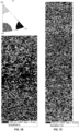
- the maps show the grains which have particular crystallographic directions within 15 degrees of the plate Normal Direction ("ND"; e.g., the vertical direction on the maps).
- ND plate Normal Direction
- Grains with a ⁇ 111> orientation within 15 degrees of ND are the darkest shaded grains (typically shown as blue for an EBSD map in accordance with the test method described herein).
- Grains with a ⁇ 100> orientation within 15 degrees of ND are the lightest shaded grains (typically shown as red for an EBSD map in accordance with the test method described herein).
- Grains with a ⁇ 110> orientation within 15 degrees of ND are the second most dark shaded (i.e., a shade in between the lightest and darkest) grains (typically shown as yellow for an EBSD map in accordance with the test method described herein). Grains which satisfy none of the criteria are white in the figures (typically shown as gray in an EBSD map in accordance with the test method described herein). A key is included with the figures to show the shading and corresponding textures.
- Figs. 1A With reference to Figs. 1A , there is seen how the teachings herein are expected to achieve a generally uniform and random crystallographic texture that is generally devoid of textural banding, and has a generally uniform grain size and distribution throughout the target body.
- the average grain size shown therein is about 71 ⁇ m. As seen, however, smaller and larger grains are shown and are contemplated as within the general teachings herein.
- the map of Fig. 1A can be prepared from a sample that may be made according to the following, A mass of tantalum powders may be employed.
- the powders may be subjected to a technique in accordance with the teachings herein for reducing the oxygen content and having a content of any scavenging metal below about 15 ppm (e.g., below about 10 ppm).
- a mass of powders can be cold isostatically pressed by applying a suitable pressure (e.g., to an initial state at s pressure of about 220 MPa) to achieve a density ranging from about 82 to about 88% of theoretical density.
- the cold isostatic pressed powders while within a container, may be hot isostatically pressed under suitable temperature and pressure conditions and for suitable time (e.g., at a temperature of about 1250 degrees C.
- the resulting hot isostatically pressed body is removed from the container and can be processed (e.g., by cutting and/or machining to final dimensions).
- the sample of Fig. 1B is a tantalum powder billet that is cold isostatically pressed, then hot isostatically pressed and then subjected to thermomechanical processing (i.e., a series of cross-rolls). Though it has an average grain size of about 48 ⁇ m, it can be seen that some textural gradient arises.
- the sample of Fig. 1C illustrates a crystallographic texture that may be realized in accordance with the teachings of published U.S. Patent Application No, 20090038362 , using asymmetric rolling of a slab prepared by ingot metallurgy (i.e., electron beam melted). It has an average grain size of about 54 ⁇ m as well.
- a target derived from powdered metal and that is conducive to sputtering is achievable in the absence of any thermomechanical processing step following consolidation.
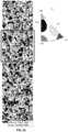
- Figs. 3A and 38 in addition to the ⁇ 100> ⁇ 110> and ⁇ 111> orientations mapped in Fig. 1A , there is depicted an expected map for the same material, but also including mapping of the expected ⁇ 211> and ⁇ 310> orientations.
- Fig. 3B is an enlarged portion of the area within the rectangle of Fig. 3A .
- a 10-degree criteria is used instead of the 15-degree criteria described herein for texture analysis. That is, the teachings of published U.S. Application No. 2009/0038362 (e.g., paras.
- orientation strengths can be calculated by counting the percentage of grains with an axis of that orientation within 10 degrees of normal to the surface of the sputtering target (y-direction in the EBSD scan).
- the lightest shaded grains correspond with a ⁇ 211> texture (which may be shown using any color, such as green, for an EBSD map in accordance with the test method described herein).
- the next lightest (i.e., slightly darker than the lightest shading) shaded grains correspond with a ⁇ 100> texture (typically shown as red for an EBSD map in accordance with the test method described herein).
- the slightly darker shaded grains than the two lightest shades correspond with a ⁇ 110> texture (typically shown as yellow for an EBSD map in accordance with the test method described herein).
- the darkest shaded grains correspond with a ⁇ 310> texture (may be shown using any color, such as pink, for an EBSD map in accordance with the test method described herein).
- the second darkest shaded grains i.e., a shade lighter than the darkest shaded grains
- correspond with a ⁇ 111 > texture typically shown as blue for an EBSD map in accordance with the test method described herein).
- the white areas, or areas with no shading, are grains in the texture maps that are not detectable (e.g., because they are outside of the proper orientation (e.g., outside of about 15° of normal direction ("ND"))).
- ND normal direction
- the volume percentage of ⁇ 110> texture can exceed that of each of ⁇ 100> and ⁇ 111 > textures.
- the volume percentage of one or both of ⁇ 211> and ⁇ 310> textures can exceed each of ⁇ 100>, ⁇ 110> and ⁇ 111 > textures.
- the total amount of ⁇ 100> ⁇ 110> and ⁇ 111> textures by volume may be about 0.4 to about 0.6 (e.g., about one half) of the total amount of ⁇ 211> and ⁇ 310> textures.
- the volume amount of ⁇ 111> texture may be below that of the ⁇ 310> texture.
- the volume percentage of ⁇ 110> texture may be about 0.5 to about 1.5 (e.g., about 0.95 or about 0.96) of the total amount of ⁇ 100> and ⁇ 111> textures.
- the volume percentage of ⁇ 110> texture may be about 0.1 to about 0.3 (e.g., about 0.2) of the total amount of ⁇ 110>, ⁇ 111 >, ⁇ 211 > and ⁇ 310> textures.
- the volume amount of the ⁇ 110> texture may be less (e.g., about one half or less) than the volume amount of the ⁇ 211> texture, the ⁇ 310> texture, or both.
- the volume amount of the ⁇ 111> texture may be less (e.g., about one half or less) than the volume amount of the ⁇ 211> texture, the ⁇ 310> texture, or both.
- the relative ratio by volume of ⁇ 211 > to ⁇ 310> textures throughout the resulting sputtering target body may be approximately the same or within about 20 percent of each other.
- the resulting sputtering target body ratio by volume of ⁇ 211> to ⁇ 310> textures throughout the resulting sputtering target body may be about 1.2:1 to about 1:1.2, e.g., about 1.1:1 to about 1:1.1, or even about 1:1,
- the relative ratio by volume of the five grain orientations ( ⁇ 100>: ⁇ 110>: ⁇ 111>: ⁇ 211>: ⁇ 310>) may be about 5-15: 15-30: 10-25: 30-45: 30-45 (e.g., about 6-12; 16-20: 10-15; 33-38; 33-38 or, may have a ratio or of about 3:6:4:12:12 if reducing by a common denominator).
- Tantalum powder samples are prepared according to the conditions of Table 2. Beds of tantalum powder having a particle size distribution of Table 1 are placed in a reactor in a plurality of stacked and spaced apart trays (e.g., four circular trays that each have a base area of about 4000 cm 2 , and are spaced from each other by about 1 cm). The reactor has a volume of about one cubic meter. In a separate tray, spaced apart from the stacked trays of tantalum powder, a bed of magnesium flakes is also placed in the reactor. The amount of the magnesium flakes is about 0.3 percent of the weight of the total amount of tantalum in the reactor. The temperature is the temperature at which the reaction takes place. The time is the duration at such temperature.
- Table 2 provides expected average results for the recited conditions.
- Table 2 Ta Bed thickness Temperature Oxygen Mg Run [cm] [C] Time [min] (ppm) (ppm) A 2.54 1000 120 38.5 3.837 B 2.54 900 60 39.5 2.891 C 2.54 800 30 125.75 2.319 D 1.27 900 30 58.5 2.397 E 1.27 800 120 75.25 1.259 F 1.27 1000 60 45 4.175 G 0.64 800 60 39.75 2.059 H 0.64 1000 30 44.5 3.105 I 0.64 900 120 45 3.691
- the present teachings also contemplate one or more steps such as cleaning, milling or otherwise machining or surface finishing a target, attaching a backing plate, or otherwise. Though such steps potentially may slightly affect the texture of the as consolidated (e.g., hot isostatically pressed) target at the surface of the target, they are not expected to impart texture modification substantially throughout the target, and thus they are consistent with the teachings herein.
- Target thickness refers to the smallest dimension of a three dimensional sputtering target.
- the plate will have an upper surface and a lower surface each having a length and a width (e.g., if rectangular), or a diameter (if circular), and will have a thickness that is the distance between the upper and lower surfaces.
- metal purities refer to purity (in weight percent) of the metals in relation to the presence of other metals, not interstitial impurities, that may arise.
- Crystallographic texture measurements herein are made in accordance with the teachings of published U.S. Application No. 20090038382 (see, paras. 159-171).
- the crystallographic texture of each sample can determined by electron backscatter diffraction (EBSD), using a 15 ⁇ m step in both horizontal and vertical directions (a step less than 15 ⁇ m is also possible, such as a 10 ⁇ m step, or can be chosen or determined based on the grain size, such as a measurement of the grain size (e.g., average grain size) divided by a number such as 3),
- the orientation strengths are calculated by counting the percentage of grains with an axis of that orientation within 15° of normal to the surface of the sputtering target (y-direction in the EBSD scan).
- samples can be taken from the center of the target structure, the mid-radius of the target structure and the edge of the structure, and the texture determined by EBSD, using a 10 ⁇ m step in both horizontal and vertical directions.
- Grain maps of the full thickness of samples are generated.
- the maps show the grains which have particular crystallographic directions within 15° of the plate Normal Direction ("ND"; the vertical direction on the maps).
- ND may be aligned with the sputtering direction of the plate.
- grains with ⁇ 100> orientation within 15° of normal direction (“ND") may be depicted as red, those with ⁇ 111> orientation within 15° of ND may be depicted as blue, and those with ⁇ 110> orientation within 15° of ND may be depicted as yellow.
- grains with ⁇ 211> orientation within 15° of ND may be depicted as any color that is able to be differentiated from the other colors of the map, such as green, and those with ⁇ 310> orientation within 15° of ND may be depicted as any color that is able to be differentiated from the other colors of the map, such as pink.
- grains which satisfy none of the criteria are typically depicted as grey. The percentages of area occupied by these color blocks form the basis of calculation of the numerical factors addressed below.
- the maps are analyzed mathematically by dividing them into two halves, a top half and bottom half.
- the height of the window e.g., in this case 90 ⁇ m
- the percentage of the area of the cut-out hole occupied by red color is calculated, as is the percentage occupied by blue color.
- the mask is moved down by-one step (e.g., 10 ⁇ m), and the calculations repeated.
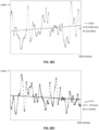
- a graph is made showing the results ( Figs. 2A1, 2A2 , 2A3 and 2B1 , 2B2, and 2B3 illustrate examples of such a graph for the top and bottom halves respectively of the sample depicted in Fig. 1A ).
- the Y axis shows the area percentage, while the X axis shows the position of the mask cut-out, (e.g., from the top or bottom of the map to mid-thickness).
- the graph could be plotted in color to correspond with the orientation depicted. For example, the red dots could refer to ⁇ 100> while the blue dots could refer to ⁇ 111 >, and green dots could refer to ⁇ 110> orientations.
- the absolute value of each individual gradient value is used.
- the data can be analyzed for the ⁇ 110> orientation in a similar way (e.g., to determine the gradient of the best-fit straight line through the ⁇ 110> data, expressed as % per mm; and the average distance (in the y-direction) of each ⁇ 110> data point from the best-fit straight line (which, if it would go below zero, is counted as zero), expressed as % (which would correspond to a ⁇ 110> banding factor)).
- Crystallographic textures are expressed for orientations that are parallel to the normal direction of the target (e.g., for a target body that is a plate, crystallographic texture is expressed for orientations that are parallel to the plate normal direction).
- Grain size measurements are made according to ASTME112-12.
- powder particle sizes are determined by screen analysis in accordance with ASTM B214 - 07(2011). Further, unless otherwise stated, particle sizes refer to pre-consolidation sizes.
- Oxygen determination for other metals can also be determined by placing a sample in a graphite crucible, which is inserted into a furnace, and held between electrodes. The furnace is purged with an inert gas (e.g., He or Ar). A sufficiently high current is passed through the crucible to increase temperature to above 2500 °C, thereby generating gasses in the furnace from the metal. The resulting gasses are released into a flowing inert gas stream. The gas stream in turn is directed to an infrared detector for measuring oxygen as CO or CO 2 . Instrument calibration can be performed using known reference materials.
- an inert gas e.g., He or Ar
- any member of a genus may be excluded from the genus; and/or any member of a Markush grouping may be excluded from the grouping.
- Percentages of the sputtering target expressed herein refer to the material of the sputtering target available for sputter deposition, and do not include other sputter target components, such as backing plates. It should be recognized that backing plates may be separately added to the sputter target bodies herein.
- Sputtering targets herein may be cylindrical in shape. They may be in the form of plates (e.g., rectangular, circular or otherwise).
- any numerical values recited herein include all values from the lower value to the upper value in increments of one unit provided that there is a separation of at least 2 units between any lower value and any higher value.
- the amount of a component, a property, or a value of a process variable such as, for example, temperature, pressure, time and the like is, for example, from 1 to 90, preferably from 20 to 80, more preferably from 30 to 70
- intermediate range values such as (for example, 15 to 85, 22 to 68, 43 to 51, 30 to 32 etc.) are within the teachings of this specification.
- individual intermediate values are also within the present teachings.
Landscapes
- Chemical & Material Sciences (AREA)
- Engineering & Computer Science (AREA)
- Mechanical Engineering (AREA)
- Manufacturing & Machinery (AREA)
- Materials Engineering (AREA)
- Organic Chemistry (AREA)
- Metallurgy (AREA)
- Physics & Mathematics (AREA)
- Chemical Kinetics & Catalysis (AREA)
- Plasma & Fusion (AREA)
- Crystallography & Structural Chemistry (AREA)
- Thermal Sciences (AREA)
- Analytical Chemistry (AREA)
- Physical Vapour Deposition (AREA)
- Powder Metallurgy (AREA)
- General Chemical & Material Sciences (AREA)
Claims (14)
- Verfahren zur Herstellung eines Sputtertargets, welches die folgenden Schritte umfasst:a. Herstellen eines Refraktärmetallpulvers nach einem Verfahren, das die folgenden Schritte umfasst:i. Anordnen einer Ausgangsmasse von Refraktärmetallpulver mit einem Anfangsgehalt an Sauerstoff in einem Reaktor;ii. Anordnen einer Masse eines reinigenden Metalls innerhalb des Reaktors, beabstandet von der Ausgangsmasse des Refraktärmetallpulvers, wobei die Masse des reinigenden Metalls und die Ausgangsmasse des Refraktärmetallpulvers nicht miteinander vermischt werden;iii. Erhitzen im Reaktor auf eine Reinigungstemperatur, um zu bewirken, dass mindestens ein Teil des reinigenden Metalls mindestens teilweise verdampft und mit mindestens einem Teil des ursprünglichen Sauerstoffgehalts reagiert, um ein reinigendes Metalloxid mit mindestens einem Teil des reinigenden Metalls zu bilden; undiv. Trennen des reinigenden Metalloxids von der Ausgangsmasse des Refraktärmetallpulvers, so dass eine resultierende Masse des Refraktärmetallpulvers gebildet wird, die einen resultierenden Sauerstoffgehalt aufweist, der geringer ist als der Ausgangsgehalt an Sauerstoff;b. Einkapseln der Masse des Refraktärmetallpulvers, das zu mindestens 95 Gew.-% aus Teilchen besteht, die eine Teilchengröße im Bereich von 10 bis 1000 µm aufweisen, wobei mindestens 10 Gew.-% der Teilchen eine Teilchengröße von mehr als 150 µm aufweisen, in einen Behälter, der so konfiguriert ist, dass er mindestens einen Teil eines Sputtertargetkörpers definiert, wobei die Teilchengröße des Pulvers als Vorverfestigungsgröße durch eine Siebanalyse gemäß ASTM B214-07 (2011) bestimmt wird; undc. heißisostatisches Pressen der Masse des Refraktärmetallpulvers, um eine resultierende verdichtete Masse mit einer anfänglichen kristallographischen Textur zu bilden, während sich die Masse des Refraktärmetallpulvers in dem Behälter befindet, wobei der Schritt des heißisostatischen Pressens unter Bedingungen durchgeführt wird, so dass die anfängliche kristallographische Textur, die in der resultierenden verdichteten Masse erreicht wird, eine theoretisch zufällige und allgemein gleichmäßige kristallographische Textur ist, wobei das Verfahren keinen Schritt der Veränderung der anfänglichen kristallographischen Textur in der gesamten resultierenden verdichteten Masse nach dem Schritt des isostatischen Heißpressens und vor dem Sputtern aufweist, und wobei der Schritt des isostatischen Heißpressens bei einer Temperatur von 950°C bis 1400°C, bei einem Druck von 100 und 300 MPa und für eine Dauer von 1 bis 12 Stunden stattfindet.
- Verfahren nach Anspruch 1, wobei die resultierende verdichtete Masse einen Sauerstoffgehalt unter 0,0125 Gew.-%, ein Metall mit einer höheren Affinität für Sauerstoff als das Refraktärmetall unter 0,0010 Gew.-% oder beides aufweist.
- Verfahren nach Anspruch 1 oder 2, wobei die Masse des Refraktärmetallpulvers Tantal als das Hauptmetall des Pulvers enthält.
- Verfahren nach einem der vorhergehenden Ansprüche, wobei die Masse des Refraktärmetallpulvers aus Tantalpulver mit einer Reinheit von mindestens 99,995 % besteht.
- Verfahren nach einem der vorhergehenden Ansprüche, wobei der Schritt des isostatischen Heißpressens bei einer Temperatur zwischen 1000°C und unter 1200°C stattfindet und wobei der Schritt des isostatischen Heißpressens bei einem Druck zwischen 100 und 250 MPa und für einen Zeitraum stattfindet, der ausreicht, um eine Dichte von mindestens 98% der theoretischen Dichte zu erreichen.
- Verfahren nach einem der vorhergehenden Ansprüche, wobei die resultierende verdichtete Masse ein Sputtertargetkörper ist, der Körner aufweist, die im Allgemeinen gleichmäßig über den Sputtertargetkörper verteilt sind, und die Körner eine durchschnittliche Korngröße von 40 bis 100 µm aufweisen, wobei die Korngröße gemäß ASTME 112-12 bestimmt wird.
- Verfahren nach einem der Ansprüche 1 bis 3, 5 oder 6, wobei die resultierende Masse des Refraktärmetallpulvers mindestens 99,95 Gewichtsprozent Tantal enthält.
- Verfahren nach einem der Ansprüche 1 bis 7, wobei die resultierende Masse des Refraktärmetallpulvers mindestens 99,995 Gew.-% Tantal enthält.
- Verfahren nach einem der Ansprüche 1 bis 8, wobei der anfängliche Sauerstoffgehalt größer als 0,03 Gew.-% ist.
- Verfahren nach einem der Ansprüche 1 bis 9, wobei sich die Ausgangsmasse des Refraktärmetallpulvers in einem Bett mit einer Tiefe von 0,3 cm bis 3,5 cm befindet.
- Verfahren nach einem der Ansprüche 1 bis 10, wobei das reinigende Metall Magnesium ist, im Reaktor in Form von Flocken vorhanden ist oder beides.
- Verfahren nach einem der Ansprüche 1 bis 11, wobei der Erhitzungsschritt das Erhitzen im Reaktor auf eine Temperatur von 800 bis 1000°C für eine Dauer von 30 Minuten bis 2 Stunden umfasst.
- Verfahren nach einem der Ansprüche 1 bis 12, wobei der resultierende Gehalt an Sauerstoff in der resultierenden Masse des Refraktärmetallpulvers in einem Bereich von 0,0001 bis 0,0125 Gew.-% liegt und/oder jedes resultierende reinigende Metall in einer Menge von 0,00003 bis 0,001 Gew.-% vorhanden ist.
- Verfahren nach einem der Ansprüche 1 bis 13, wobei die resultierende verdichtete Masse ein Sputtertargetkörper ist, der eine gleichmäßige kristallografische Textur im gesamten Sputtertargetkörper aufweist und frei von kristallografischen Texturbändern und/oder kristallografischen Texturgradienten ist.
Applications Claiming Priority (3)
| Application Number | Priority Date | Filing Date | Title |
|---|---|---|---|
| US201461978341P | 2014-04-11 | 2014-04-11 | |
| US201461978349P | 2014-04-11 | 2014-04-11 | |
| PCT/US2015/024928 WO2015157421A1 (en) | 2014-04-11 | 2015-04-08 | High purity refractory metal sputtering targets which have a uniform random texture manufactured by hot isostatic pressing high purity refractory metal powders |
Publications (2)
| Publication Number | Publication Date |
|---|---|
| EP3129176A1 EP3129176A1 (de) | 2017-02-15 |
| EP3129176B1 true EP3129176B1 (de) | 2024-10-09 |
Family
ID=54264613
Family Applications (1)
| Application Number | Title | Priority Date | Filing Date |
|---|---|---|---|
| EP15717391.5A Active EP3129176B1 (de) | 2014-04-11 | 2015-04-08 | Hochreine refraktärmetallsputter-targets mit gleichmässigem zufallsgefüge hergestellt durch heissisostatisches verpressen von hochreinen refraktärmetallpulvern |
Country Status (5)
| Country | Link |
|---|---|
| US (2) | US10023953B2 (de) |
| EP (1) | EP3129176B1 (de) |
| JP (1) | JP6573629B2 (de) |
| TW (1) | TWI600784B (de) |
| WO (1) | WO2015157421A1 (de) |
Families Citing this family (13)
| Publication number | Priority date | Publication date | Assignee | Title |
|---|---|---|---|---|
| JP7174476B2 (ja) | 2017-03-31 | 2022-11-17 | Jx金属株式会社 | タングステンターゲット |
| KR102389784B1 (ko) | 2018-03-05 | 2022-04-22 | 글로벌 어드밴스드 메탈스 유에스에이, 아이엔씨. | 구형 분말을 함유하는 애노드 및 커패시터 |
| CA3091448C (en) | 2018-03-05 | 2024-03-19 | Craig Sungail | Spherical tantalum powder, products containing the same, and methods of making the same |
| KR102490248B1 (ko) * | 2018-03-05 | 2023-01-20 | 글로벌 어드밴스드 메탈스 유에스에이, 아이엔씨. | 분말 야금 스퍼터링 표적 및 그의 생성 방법 |
| US11289276B2 (en) | 2018-10-30 | 2022-03-29 | Global Advanced Metals Japan K.K. | Porous metal foil and capacitor anodes made therefrom and methods of making same |
| WO2020195121A1 (ja) * | 2019-03-26 | 2020-10-01 | Jx金属株式会社 | ニオブスパッタリングターゲット |
| CN110983277A (zh) * | 2019-12-30 | 2020-04-10 | 广州市尤特新材料有限公司 | 一种用于钕铁硼永磁材料的旋转稀土靶材及制备方法和修复方法 |
| CN111230129B (zh) * | 2020-03-18 | 2022-08-16 | 宁波江丰电子材料股份有限公司 | 一种钨钛混粉方法 |
| CN111438355B (zh) * | 2020-04-13 | 2022-02-22 | 河北晟华新材料科技有限公司 | 一种铬铝硅靶材及其制备方法 |
| WO2025006859A1 (en) | 2023-06-29 | 2025-01-02 | Materion Corporation | Metals and metal alloys for sputtering targets |
| CN116855807B (zh) * | 2023-08-01 | 2025-12-19 | 河南科技大学 | 一种超细晶高致密钽钨合金及其制备方法 |
| WO2025129000A1 (en) | 2023-12-15 | 2025-06-19 | Materion Corporation | Refractory metal plates |
| TWI874167B (zh) * | 2024-03-18 | 2025-02-21 | 旭鈺實業股份有限公司 | 用於濺鍍靶材的三元鋁合金及其製作方法 |
Citations (2)
| Publication number | Priority date | Publication date | Assignee | Title |
|---|---|---|---|---|
| WO2000031310A1 (en) * | 1998-11-25 | 2000-06-02 | Cabot Corporation | High purity tantalum and products containing the same like sputter targets |
| US6261337B1 (en) * | 1999-08-19 | 2001-07-17 | Prabhat Kumar | Low oxygen refractory metal powder for powder metallurgy |
Family Cites Families (22)
| Publication number | Priority date | Publication date | Assignee | Title |
|---|---|---|---|---|
| CH677530A5 (de) | 1988-11-17 | 1991-05-31 | Eidgenoess Munitionsfab Thun | |
| US5242481A (en) * | 1989-06-26 | 1993-09-07 | Cabot Corporation | Method of making powders and products of tantalum and niobium |
| JP2001020065A (ja) | 1999-07-07 | 2001-01-23 | Hitachi Metals Ltd | スパッタリング用ターゲット及びその製造方法ならびに高融点金属粉末材料 |
| US6521173B2 (en) | 1999-08-19 | 2003-02-18 | H.C. Starck, Inc. | Low oxygen refractory metal powder for powder metallurgy |
| MXPA03007490A (es) | 2001-02-20 | 2004-09-06 | Starck H C Inc | Chapas de metal refractario con textura uniforme y metodos de hacerlas. |
| US7081148B2 (en) | 2001-09-18 | 2006-07-25 | Praxair S.T. Technology, Inc. | Textured-grain-powder metallurgy tantalum sputter target |
| US6770154B2 (en) | 2001-09-18 | 2004-08-03 | Praxair S.T. Technology, Inc. | Textured-grain-powder metallurgy tantalum sputter target |
| JP3633543B2 (ja) * | 2001-10-23 | 2005-03-30 | 住友金属鉱山株式会社 | ニオブおよび/またはタンタルの粉末の製造法 |
| US20040016635A1 (en) | 2002-07-19 | 2004-01-29 | Ford Robert B. | Monolithic sputtering target assembly |
| TWI341337B (en) * | 2003-01-07 | 2011-05-01 | Cabot Corp | Powder metallurgy sputtering targets and methods of producing same |
| US7381282B2 (en) | 2004-04-07 | 2008-06-03 | Hitachi Metals, Ltd. | Co alloy target and its production method, soft magnetic film for perpendicular magnetic recording and perpendicular magnetic recording medium |
| WO2006001976A2 (en) | 2004-06-15 | 2006-01-05 | Tosoh Smd, Inc. | High purity target manufacturing methods |
| EP1880036A2 (de) | 2005-05-05 | 2008-01-23 | H.C. Starck GmbH | Beschichtungsverfahren zur herstellung oder wiederverarbeitung von sputtertargets und röntgenanoden |
| US20080078268A1 (en) | 2006-10-03 | 2008-04-03 | H.C. Starck Inc. | Process for preparing metal powders having low oxygen content, powders so-produced and uses thereof |
| US8197894B2 (en) | 2007-05-04 | 2012-06-12 | H.C. Starck Gmbh | Methods of forming sputtering targets |
| US20090010792A1 (en) * | 2007-07-02 | 2009-01-08 | Heraeus Inc. | Brittle metal alloy sputtering targets and method of fabricating same |
| JP5389802B2 (ja) | 2007-08-06 | 2014-01-15 | エイチ.シー. スターク インコーポレイテッド | 組織の均一性が改善された高融点金属プレート |
| US8250895B2 (en) | 2007-08-06 | 2012-08-28 | H.C. Starck Inc. | Methods and apparatus for controlling texture of plates and sheets by tilt rolling |
| JP5342810B2 (ja) | 2008-06-09 | 2013-11-13 | 株式会社コベルコ科研 | Al基合金スパッタリングターゲット材の製造方法 |
| MX347082B (es) * | 2010-02-15 | 2017-04-11 | Federal Mogul Corp | Una aleación patrón para producir partes de acero endurecidas sinterizadas y proceso para la producción de partes endurecidas sinterizadas. |
| JP5165100B1 (ja) * | 2011-11-01 | 2013-03-21 | 三菱マテリアル株式会社 | スパッタリングターゲット及びその製造方法 |
| CN102513537B (zh) * | 2011-12-06 | 2013-07-17 | 中国航空工业集团公司北京航空材料研究院 | 一种氩气雾化粉末TiAl合金板材的制备方法 |
-
2015
- 2015-04-08 EP EP15717391.5A patent/EP3129176B1/de active Active
- 2015-04-08 JP JP2016561807A patent/JP6573629B2/ja active Active
- 2015-04-08 WO PCT/US2015/024928 patent/WO2015157421A1/en not_active Ceased
- 2015-04-08 US US14/681,660 patent/US10023953B2/en active Active
- 2015-04-13 TW TW104111728A patent/TWI600784B/zh active
-
2018
- 2018-06-19 US US16/012,092 patent/US20190032196A1/en not_active Abandoned
Patent Citations (2)
| Publication number | Priority date | Publication date | Assignee | Title |
|---|---|---|---|---|
| WO2000031310A1 (en) * | 1998-11-25 | 2000-06-02 | Cabot Corporation | High purity tantalum and products containing the same like sputter targets |
| US6261337B1 (en) * | 1999-08-19 | 2001-07-17 | Prabhat Kumar | Low oxygen refractory metal powder for powder metallurgy |
Also Published As
| Publication number | Publication date |
|---|---|
| TW201602380A (zh) | 2016-01-16 |
| US20150292081A1 (en) | 2015-10-15 |
| JP2017517627A (ja) | 2017-06-29 |
| US10023953B2 (en) | 2018-07-17 |
| US20190032196A1 (en) | 2019-01-31 |
| WO2015157421A1 (en) | 2015-10-15 |
| WO2015157421A9 (en) | 2015-12-03 |
| TWI600784B (zh) | 2017-10-01 |
| JP6573629B2 (ja) | 2019-09-11 |
| EP3129176A1 (de) | 2017-02-15 |
Similar Documents
| Publication | Publication Date | Title |
|---|---|---|
| EP3129176B1 (de) | Hochreine refraktärmetallsputter-targets mit gleichmässigem zufallsgefüge hergestellt durch heissisostatisches verpressen von hochreinen refraktärmetallpulvern | |
| KR102490248B1 (ko) | 분말 야금 스퍼터링 표적 및 그의 생성 방법 | |
| USRE40100E1 (en) | Fabrication of B/C/N/O/Si doped sputtering targets | |
| EP2707520B1 (de) | Verbund-target | |
| WO1995004167A1 (en) | High melting point metallic silicide target and method for producing the same, high melting point metallic silicide film and semiconductor device | |
| EP3124647B1 (de) | Sputtertarget mit al-te-cu-zr-legierung und verfahren zur herstellung davon | |
| TWI675116B (zh) | Ti-Al合金濺鍍靶 | |
| US20040062675A1 (en) | Fabrication of ductile intermetallic sputtering targets | |
| JP7831285B2 (ja) | 金属-Si系粉末、その製造方法、並びに金属-Si系焼結体、スパッタリングターゲット及び金属-Si系薄膜の製造方法 | |
| WO2025006859A1 (en) | Metals and metal alloys for sputtering targets | |
| CN119663035B (zh) | 一种Al-Sc合金及其制备方法和应用 | |
| JPWO1995004167A1 (ja) | 高融点金属シリサイドターゲット,その製造方法,高融点金属シリサイド薄膜および半導体装置 | |
| JP3551355B2 (ja) | Ruターゲットおよびその製造方法 | |
| JPS62174373A (ja) | クロムタ−ゲツト材及びその製造方法 | |
| WO2025129000A1 (en) | Refractory metal plates | |
| EP3170916B1 (de) | Sputtertarget mit al-te-cu-zr-legierung und verfahren zur herstellung davon |
Legal Events
| Date | Code | Title | Description |
|---|---|---|---|
| STAA | Information on the status of an ep patent application or granted ep patent |
Free format text: STATUS: THE INTERNATIONAL PUBLICATION HAS BEEN MADE |
|
| PUAI | Public reference made under article 153(3) epc to a published international application that has entered the european phase |
Free format text: ORIGINAL CODE: 0009012 |
|
| STAA | Information on the status of an ep patent application or granted ep patent |
Free format text: STATUS: REQUEST FOR EXAMINATION WAS MADE |
|
| 17P | Request for examination filed |
Effective date: 20161111 |
|
| AK | Designated contracting states |
Kind code of ref document: A1 Designated state(s): AL AT BE BG CH CY CZ DE DK EE ES FI FR GB GR HR HU IE IS IT LI LT LU LV MC MK MT NL NO PL PT RO RS SE SI SK SM TR |
|
| AX | Request for extension of the european patent |
Extension state: BA ME |
|
| DAV | Request for validation of the european patent (deleted) | ||
| DAX | Request for extension of the european patent (deleted) | ||
| STAA | Information on the status of an ep patent application or granted ep patent |
Free format text: STATUS: EXAMINATION IS IN PROGRESS |
|
| 17Q | First examination report despatched |
Effective date: 20190730 |
|
| RAP3 | Party data changed (applicant data changed or rights of an application transferred) |
Owner name: MATERION NEWTON INC. |
|
| P01 | Opt-out of the competence of the unified patent court (upc) registered |
Effective date: 20230509 |
|
| GRAP | Despatch of communication of intention to grant a patent |
Free format text: ORIGINAL CODE: EPIDOSNIGR1 |
|
| STAA | Information on the status of an ep patent application or granted ep patent |
Free format text: STATUS: GRANT OF PATENT IS INTENDED |
|
| RIC1 | Information provided on ipc code assigned before grant |
Ipc: B22F 3/12 20060101ALI20231124BHEP Ipc: B22F 3/02 20060101ALI20231124BHEP Ipc: B22F 3/15 20060101AFI20231124BHEP Ipc: B22F 3/10 20060101ALN20231124BHEP Ipc: C22C 1/04 20060101ALI20231124BHEP Ipc: H01J 37/34 20060101ALI20231124BHEP Ipc: C22F 1/18 20060101ALI20231124BHEP Ipc: C23C 14/34 20060101ALI20231124BHEP Ipc: B22F 1/052 20220101ALI20231124BHEP |
|
| RIC1 | Information provided on ipc code assigned before grant |
Ipc: B22F 3/10 20060101ALN20231207BHEP Ipc: C22C 1/04 20060101ALI20231207BHEP Ipc: H01J 37/34 20060101ALI20231207BHEP Ipc: C22F 1/18 20060101ALI20231207BHEP Ipc: C23C 14/34 20060101ALI20231207BHEP Ipc: B22F 1/052 20220101ALI20231207BHEP Ipc: B22F 3/12 20060101ALI20231207BHEP Ipc: B22F 3/02 20060101ALI20231207BHEP Ipc: B22F 3/15 20060101AFI20231207BHEP |
|
| INTG | Intention to grant announced |
Effective date: 20240102 |
|
| RIN1 | Information on inventor provided before grant (corrected) |
Inventor name: HAAS, HELMUT Inventor name: HAGYMASI, MARCEL Inventor name: FLANIGAN, JOSEPH Inventor name: AIMONE, PAUL Inventor name: HOGAN, PATRICK |
|
| GRAS | Grant fee paid |
Free format text: ORIGINAL CODE: EPIDOSNIGR3 |
|
| GRAA | (expected) grant |
Free format text: ORIGINAL CODE: 0009210 |
|
| STAA | Information on the status of an ep patent application or granted ep patent |
Free format text: STATUS: THE PATENT HAS BEEN GRANTED |
|
| AK | Designated contracting states |
Kind code of ref document: B1 Designated state(s): AL AT BE BG CH CY CZ DE DK EE ES FI FR GB GR HR HU IE IS IT LI LT LU LV MC MK MT NL NO PL PT RO RS SE SI SK SM TR |
|
| REG | Reference to a national code |
Ref country code: GB Ref legal event code: FG4D |
|
| REG | Reference to a national code |
Ref country code: CH Ref legal event code: EP |
|
| REG | Reference to a national code |
Ref country code: DE Ref legal event code: R096 Ref document number: 602015090077 Country of ref document: DE |
|
| REG | Reference to a national code |
Ref country code: IE Ref legal event code: FG4D |
|
| REG | Reference to a national code |
Ref country code: LT Ref legal event code: MG9D |
|
| REG | Reference to a national code |
Ref country code: NL Ref legal event code: MP Effective date: 20241009 |
|
| PG25 | Lapsed in a contracting state [announced via postgrant information from national office to epo] |
Ref country code: NL Free format text: LAPSE BECAUSE OF FAILURE TO SUBMIT A TRANSLATION OF THE DESCRIPTION OR TO PAY THE FEE WITHIN THE PRESCRIBED TIME-LIMIT Effective date: 20241009 |
|
| PG25 | Lapsed in a contracting state [announced via postgrant information from national office to epo] |
Ref country code: NL Free format text: LAPSE BECAUSE OF FAILURE TO SUBMIT A TRANSLATION OF THE DESCRIPTION OR TO PAY THE FEE WITHIN THE PRESCRIBED TIME-LIMIT Effective date: 20241009 |
|
| PG25 | Lapsed in a contracting state [announced via postgrant information from national office to epo] |
Ref country code: IS Free format text: LAPSE BECAUSE OF FAILURE TO SUBMIT A TRANSLATION OF THE DESCRIPTION OR TO PAY THE FEE WITHIN THE PRESCRIBED TIME-LIMIT Effective date: 20250209 Ref country code: HR Free format text: LAPSE BECAUSE OF FAILURE TO SUBMIT A TRANSLATION OF THE DESCRIPTION OR TO PAY THE FEE WITHIN THE PRESCRIBED TIME-LIMIT Effective date: 20241009 Ref country code: PT Free format text: LAPSE BECAUSE OF FAILURE TO SUBMIT A TRANSLATION OF THE DESCRIPTION OR TO PAY THE FEE WITHIN THE PRESCRIBED TIME-LIMIT Effective date: 20250210 |
|
| PG25 | Lapsed in a contracting state [announced via postgrant information from national office to epo] |
Ref country code: FI Free format text: LAPSE BECAUSE OF FAILURE TO SUBMIT A TRANSLATION OF THE DESCRIPTION OR TO PAY THE FEE WITHIN THE PRESCRIBED TIME-LIMIT Effective date: 20241009 |
|
| PG25 | Lapsed in a contracting state [announced via postgrant information from national office to epo] |
Ref country code: BG Free format text: LAPSE BECAUSE OF FAILURE TO SUBMIT A TRANSLATION OF THE DESCRIPTION OR TO PAY THE FEE WITHIN THE PRESCRIBED TIME-LIMIT Effective date: 20241009 |
|
| PG25 | Lapsed in a contracting state [announced via postgrant information from national office to epo] |
Ref country code: ES Free format text: LAPSE BECAUSE OF FAILURE TO SUBMIT A TRANSLATION OF THE DESCRIPTION OR TO PAY THE FEE WITHIN THE PRESCRIBED TIME-LIMIT Effective date: 20241009 |
|
| PG25 | Lapsed in a contracting state [announced via postgrant information from national office to epo] |
Ref country code: NO Free format text: LAPSE BECAUSE OF FAILURE TO SUBMIT A TRANSLATION OF THE DESCRIPTION OR TO PAY THE FEE WITHIN THE PRESCRIBED TIME-LIMIT Effective date: 20250109 |
|
| PG25 | Lapsed in a contracting state [announced via postgrant information from national office to epo] |
Ref country code: GR Free format text: LAPSE BECAUSE OF FAILURE TO SUBMIT A TRANSLATION OF THE DESCRIPTION OR TO PAY THE FEE WITHIN THE PRESCRIBED TIME-LIMIT Effective date: 20250110 Ref country code: LV Free format text: LAPSE BECAUSE OF FAILURE TO SUBMIT A TRANSLATION OF THE DESCRIPTION OR TO PAY THE FEE WITHIN THE PRESCRIBED TIME-LIMIT Effective date: 20241009 |
|
| PG25 | Lapsed in a contracting state [announced via postgrant information from national office to epo] |
Ref country code: PL Free format text: LAPSE BECAUSE OF FAILURE TO SUBMIT A TRANSLATION OF THE DESCRIPTION OR TO PAY THE FEE WITHIN THE PRESCRIBED TIME-LIMIT Effective date: 20241009 |
|
| PGFP | Annual fee paid to national office [announced via postgrant information from national office to epo] |
Ref country code: GB Payment date: 20250327 Year of fee payment: 11 |
|
| PG25 | Lapsed in a contracting state [announced via postgrant information from national office to epo] |
Ref country code: RS Free format text: LAPSE BECAUSE OF FAILURE TO SUBMIT A TRANSLATION OF THE DESCRIPTION OR TO PAY THE FEE WITHIN THE PRESCRIBED TIME-LIMIT Effective date: 20250109 |
|
| PG25 | Lapsed in a contracting state [announced via postgrant information from national office to epo] |
Ref country code: SM Free format text: LAPSE BECAUSE OF FAILURE TO SUBMIT A TRANSLATION OF THE DESCRIPTION OR TO PAY THE FEE WITHIN THE PRESCRIBED TIME-LIMIT Effective date: 20241009 |
|
| PGFP | Annual fee paid to national office [announced via postgrant information from national office to epo] |
Ref country code: DE Payment date: 20250325 Year of fee payment: 11 |
|
| PG25 | Lapsed in a contracting state [announced via postgrant information from national office to epo] |
Ref country code: DK Free format text: LAPSE BECAUSE OF FAILURE TO SUBMIT A TRANSLATION OF THE DESCRIPTION OR TO PAY THE FEE WITHIN THE PRESCRIBED TIME-LIMIT Effective date: 20241009 |
|
| REG | Reference to a national code |
Ref country code: DE Ref legal event code: R097 Ref document number: 602015090077 Country of ref document: DE |
|
| PG25 | Lapsed in a contracting state [announced via postgrant information from national office to epo] |
Ref country code: EE Free format text: LAPSE BECAUSE OF FAILURE TO SUBMIT A TRANSLATION OF THE DESCRIPTION OR TO PAY THE FEE WITHIN THE PRESCRIBED TIME-LIMIT Effective date: 20241009 |
|
| PGFP | Annual fee paid to national office [announced via postgrant information from national office to epo] |
Ref country code: FR Payment date: 20250401 Year of fee payment: 11 |
|
| PG25 | Lapsed in a contracting state [announced via postgrant information from national office to epo] |
Ref country code: RO Free format text: LAPSE BECAUSE OF FAILURE TO SUBMIT A TRANSLATION OF THE DESCRIPTION OR TO PAY THE FEE WITHIN THE PRESCRIBED TIME-LIMIT Effective date: 20241009 |
|
| PGFP | Annual fee paid to national office [announced via postgrant information from national office to epo] |
Ref country code: AT Payment date: 20250325 Year of fee payment: 11 |
|
| PG25 | Lapsed in a contracting state [announced via postgrant information from national office to epo] |
Ref country code: SK Free format text: LAPSE BECAUSE OF FAILURE TO SUBMIT A TRANSLATION OF THE DESCRIPTION OR TO PAY THE FEE WITHIN THE PRESCRIBED TIME-LIMIT Effective date: 20241009 |
|
| PG25 | Lapsed in a contracting state [announced via postgrant information from national office to epo] |
Ref country code: CZ Free format text: LAPSE BECAUSE OF FAILURE TO SUBMIT A TRANSLATION OF THE DESCRIPTION OR TO PAY THE FEE WITHIN THE PRESCRIBED TIME-LIMIT Effective date: 20241009 |
|
| PG25 | Lapsed in a contracting state [announced via postgrant information from national office to epo] |
Ref country code: IT Free format text: LAPSE BECAUSE OF FAILURE TO SUBMIT A TRANSLATION OF THE DESCRIPTION OR TO PAY THE FEE WITHIN THE PRESCRIBED TIME-LIMIT Effective date: 20241009 |
|
| PLBE | No opposition filed within time limit |
Free format text: ORIGINAL CODE: 0009261 |
|
| STAA | Information on the status of an ep patent application or granted ep patent |
Free format text: STATUS: NO OPPOSITION FILED WITHIN TIME LIMIT |
|
| PG25 | Lapsed in a contracting state [announced via postgrant information from national office to epo] |
Ref country code: SE Free format text: LAPSE BECAUSE OF FAILURE TO SUBMIT A TRANSLATION OF THE DESCRIPTION OR TO PAY THE FEE WITHIN THE PRESCRIBED TIME-LIMIT Effective date: 20241009 |
|
| 26N | No opposition filed |
Effective date: 20250710 |
|
| REG | Reference to a national code |
Ref country code: CH Ref legal event code: H13 Free format text: ST27 STATUS EVENT CODE: U-0-0-H10-H13 (AS PROVIDED BY THE NATIONAL OFFICE) Effective date: 20251125 |
|
| PG25 | Lapsed in a contracting state [announced via postgrant information from national office to epo] |
Ref country code: LU Free format text: LAPSE BECAUSE OF NON-PAYMENT OF DUE FEES Effective date: 20250408 |
|
| PG25 | Lapsed in a contracting state [announced via postgrant information from national office to epo] |
Ref country code: MC Free format text: LAPSE BECAUSE OF FAILURE TO SUBMIT A TRANSLATION OF THE DESCRIPTION OR TO PAY THE FEE WITHIN THE PRESCRIBED TIME-LIMIT Effective date: 20241009 |
|
| REG | Reference to a national code |
Ref country code: BE Ref legal event code: MM Effective date: 20250430 |
|
| PG25 | Lapsed in a contracting state [announced via postgrant information from national office to epo] |
Ref country code: BE Free format text: LAPSE BECAUSE OF NON-PAYMENT OF DUE FEES Effective date: 20250430 |
|
| PG25 | Lapsed in a contracting state [announced via postgrant information from national office to epo] |
Ref country code: CH Free format text: LAPSE BECAUSE OF NON-PAYMENT OF DUE FEES Effective date: 20250430 |