EP3129151B1 - Filtervorrichtung - Google Patents
Filtervorrichtung Download PDFInfo
- Publication number
- EP3129151B1 EP3129151B1 EP15719801.1A EP15719801A EP3129151B1 EP 3129151 B1 EP3129151 B1 EP 3129151B1 EP 15719801 A EP15719801 A EP 15719801A EP 3129151 B1 EP3129151 B1 EP 3129151B1
- Authority
- EP
- European Patent Office
- Prior art keywords
- structures
- collecting
- emitting structures
- plate
- emitting
- Prior art date
- Legal status (The legal status is an assumption and is not a legal conclusion. Google has not performed a legal analysis and makes no representation as to the accuracy of the status listed.)
- Active
Links
Images


Classifications
-
- B—PERFORMING OPERATIONS; TRANSPORTING
- B03—SEPARATION OF SOLID MATERIALS USING LIQUIDS OR USING PNEUMATIC TABLES OR JIGS; MAGNETIC OR ELECTROSTATIC SEPARATION OF SOLID MATERIALS FROM SOLID MATERIALS OR FLUIDS; SEPARATION BY HIGH-VOLTAGE ELECTRIC FIELDS
- B03C—MAGNETIC OR ELECTROSTATIC SEPARATION OF SOLID MATERIALS FROM SOLID MATERIALS OR FLUIDS; SEPARATION BY HIGH-VOLTAGE ELECTRIC FIELDS
- B03C3/00—Separating dispersed particles from gases or vapour, e.g. air, by electrostatic effect
- B03C3/32—Transportable units, e.g. for cleaning room air
-
- B—PERFORMING OPERATIONS; TRANSPORTING
- B03—SEPARATION OF SOLID MATERIALS USING LIQUIDS OR USING PNEUMATIC TABLES OR JIGS; MAGNETIC OR ELECTROSTATIC SEPARATION OF SOLID MATERIALS FROM SOLID MATERIALS OR FLUIDS; SEPARATION BY HIGH-VOLTAGE ELECTRIC FIELDS
- B03C—MAGNETIC OR ELECTROSTATIC SEPARATION OF SOLID MATERIALS FROM SOLID MATERIALS OR FLUIDS; SEPARATION BY HIGH-VOLTAGE ELECTRIC FIELDS
- B03C3/00—Separating dispersed particles from gases or vapour, e.g. air, by electrostatic effect
- B03C3/01—Pretreatment of the gases prior to electrostatic precipitation
- B03C3/011—Prefiltering; Flow controlling
-
- B—PERFORMING OPERATIONS; TRANSPORTING
- B03—SEPARATION OF SOLID MATERIALS USING LIQUIDS OR USING PNEUMATIC TABLES OR JIGS; MAGNETIC OR ELECTROSTATIC SEPARATION OF SOLID MATERIALS FROM SOLID MATERIALS OR FLUIDS; SEPARATION BY HIGH-VOLTAGE ELECTRIC FIELDS
- B03C—MAGNETIC OR ELECTROSTATIC SEPARATION OF SOLID MATERIALS FROM SOLID MATERIALS OR FLUIDS; SEPARATION BY HIGH-VOLTAGE ELECTRIC FIELDS
- B03C3/00—Separating dispersed particles from gases or vapour, e.g. air, by electrostatic effect
- B03C3/02—Plant or installations having external electricity supply
- B03C3/04—Plant or installations having external electricity supply dry type
- B03C3/08—Plant or installations having external electricity supply dry type characterised by presence of stationary flat electrodes arranged with their flat surfaces parallel to the gas stream
-
- B—PERFORMING OPERATIONS; TRANSPORTING
- B03—SEPARATION OF SOLID MATERIALS USING LIQUIDS OR USING PNEUMATIC TABLES OR JIGS; MAGNETIC OR ELECTROSTATIC SEPARATION OF SOLID MATERIALS FROM SOLID MATERIALS OR FLUIDS; SEPARATION BY HIGH-VOLTAGE ELECTRIC FIELDS
- B03C—MAGNETIC OR ELECTROSTATIC SEPARATION OF SOLID MATERIALS FROM SOLID MATERIALS OR FLUIDS; SEPARATION BY HIGH-VOLTAGE ELECTRIC FIELDS
- B03C3/00—Separating dispersed particles from gases or vapour, e.g. air, by electrostatic effect
- B03C3/02—Plant or installations having external electricity supply
- B03C3/04—Plant or installations having external electricity supply dry type
- B03C3/09—Plant or installations having external electricity supply dry type characterised by presence of stationary flat electrodes arranged with their flat surfaces at right angles to the gas stream
-
- B—PERFORMING OPERATIONS; TRANSPORTING
- B03—SEPARATION OF SOLID MATERIALS USING LIQUIDS OR USING PNEUMATIC TABLES OR JIGS; MAGNETIC OR ELECTROSTATIC SEPARATION OF SOLID MATERIALS FROM SOLID MATERIALS OR FLUIDS; SEPARATION BY HIGH-VOLTAGE ELECTRIC FIELDS
- B03C—MAGNETIC OR ELECTROSTATIC SEPARATION OF SOLID MATERIALS FROM SOLID MATERIALS OR FLUIDS; SEPARATION BY HIGH-VOLTAGE ELECTRIC FIELDS
- B03C3/00—Separating dispersed particles from gases or vapour, e.g. air, by electrostatic effect
- B03C3/02—Plant or installations having external electricity supply
- B03C3/04—Plant or installations having external electricity supply dry type
- B03C3/14—Plant or installations having external electricity supply dry type characterised by the additional use of mechanical effects, e.g. gravity
- B03C3/155—Filtration
-
- B—PERFORMING OPERATIONS; TRANSPORTING
- B03—SEPARATION OF SOLID MATERIALS USING LIQUIDS OR USING PNEUMATIC TABLES OR JIGS; MAGNETIC OR ELECTROSTATIC SEPARATION OF SOLID MATERIALS FROM SOLID MATERIALS OR FLUIDS; SEPARATION BY HIGH-VOLTAGE ELECTRIC FIELDS
- B03C—MAGNETIC OR ELECTROSTATIC SEPARATION OF SOLID MATERIALS FROM SOLID MATERIALS OR FLUIDS; SEPARATION BY HIGH-VOLTAGE ELECTRIC FIELDS
- B03C3/00—Separating dispersed particles from gases or vapour, e.g. air, by electrostatic effect
- B03C3/34—Constructional details or accessories or operation thereof
- B03C3/36—Controlling flow of gases or vapour
- B03C3/368—Controlling flow of gases or vapour by other than static mechanical means, e.g. internal ventilator or recycler
-
- B—PERFORMING OPERATIONS; TRANSPORTING
- B03—SEPARATION OF SOLID MATERIALS USING LIQUIDS OR USING PNEUMATIC TABLES OR JIGS; MAGNETIC OR ELECTROSTATIC SEPARATION OF SOLID MATERIALS FROM SOLID MATERIALS OR FLUIDS; SEPARATION BY HIGH-VOLTAGE ELECTRIC FIELDS
- B03C—MAGNETIC OR ELECTROSTATIC SEPARATION OF SOLID MATERIALS FROM SOLID MATERIALS OR FLUIDS; SEPARATION BY HIGH-VOLTAGE ELECTRIC FIELDS
- B03C3/00—Separating dispersed particles from gases or vapour, e.g. air, by electrostatic effect
- B03C3/34—Constructional details or accessories or operation thereof
- B03C3/40—Electrode constructions
- B03C3/41—Ionising-electrodes
-
- B—PERFORMING OPERATIONS; TRANSPORTING
- B03—SEPARATION OF SOLID MATERIALS USING LIQUIDS OR USING PNEUMATIC TABLES OR JIGS; MAGNETIC OR ELECTROSTATIC SEPARATION OF SOLID MATERIALS FROM SOLID MATERIALS OR FLUIDS; SEPARATION BY HIGH-VOLTAGE ELECTRIC FIELDS
- B03C—MAGNETIC OR ELECTROSTATIC SEPARATION OF SOLID MATERIALS FROM SOLID MATERIALS OR FLUIDS; SEPARATION BY HIGH-VOLTAGE ELECTRIC FIELDS
- B03C3/00—Separating dispersed particles from gases or vapour, e.g. air, by electrostatic effect
- B03C3/34—Constructional details or accessories or operation thereof
- B03C3/40—Electrode constructions
- B03C3/45—Collecting-electrodes
- B03C3/47—Collecting-electrodes flat, e.g. plates, discs, gratings
-
- B—PERFORMING OPERATIONS; TRANSPORTING
- B03—SEPARATION OF SOLID MATERIALS USING LIQUIDS OR USING PNEUMATIC TABLES OR JIGS; MAGNETIC OR ELECTROSTATIC SEPARATION OF SOLID MATERIALS FROM SOLID MATERIALS OR FLUIDS; SEPARATION BY HIGH-VOLTAGE ELECTRIC FIELDS
- B03C—MAGNETIC OR ELECTROSTATIC SEPARATION OF SOLID MATERIALS FROM SOLID MATERIALS OR FLUIDS; SEPARATION BY HIGH-VOLTAGE ELECTRIC FIELDS
- B03C2201/00—Details of magnetic or electrostatic separation
- B03C2201/10—Ionising electrode with two or more serrated ends or sides
-
- B—PERFORMING OPERATIONS; TRANSPORTING
- B03—SEPARATION OF SOLID MATERIALS USING LIQUIDS OR USING PNEUMATIC TABLES OR JIGS; MAGNETIC OR ELECTROSTATIC SEPARATION OF SOLID MATERIALS FROM SOLID MATERIALS OR FLUIDS; SEPARATION BY HIGH-VOLTAGE ELECTRIC FIELDS
- B03C—MAGNETIC OR ELECTROSTATIC SEPARATION OF SOLID MATERIALS FROM SOLID MATERIALS OR FLUIDS; SEPARATION BY HIGH-VOLTAGE ELECTRIC FIELDS
- B03C2201/00—Details of magnetic or electrostatic separation
- B03C2201/30—Details of magnetic or electrostatic separation for use in or with vehicles
Definitions
- the present invention relates to a device for purifying a gaseous medium loaded with particles of all kinds, such as dust particles, organic particles in suspension in the exhaust gases of all kinds and in particular from diesel engines. ..
- It is more particularly intended for use in an industrial installation, an establishment (hospital, restaurant, etc.) or even a building for residential use (house, apartment), in particular in the form of a mobile device.
- This treatment device comprises a corona-effect electrofilter comprising a longitudinal casing of cylindrical shape in which extends a longitudinal passage for the gases to be treated, an emissive structure extending longitudinally in the center of the passage and a collecting structure extending longitudinally between the passage and the envelope and comprising a plurality of cavities forming housings for trapping the particles contained in the gaseous medium, the emissive structure comprising a plurality of serrated plates arranged transversely to the longitudinal direction and forming points directed towards the collecting structure . These serrated plates are all carried by a rod connected to a circuit providing a stabilized high voltage.
- Another device for purifying a gaseous medium loaded with particles is described in JP S58 119355 A .
- the present invention aims to provide a device of this type, better suited to the uses mentioned above, while remaining effective, and also leading to other advantages.
- the present invention proposes a purification device optimized in terms of efficiency as well as the aforementioned uses.
- each of the emissive structures or electrodes as desired, in particular to obtain for example effects of ozone production or not, to play with the flow of the gaseous medium in the filtration chamber , or even bringing each of the electrodes individually to a different voltage.
- these arrangements also make it possible to produce a device that is easy to manufacture and also to maintain which, moreover, can be produced, as needed, in the form of a compact structure.
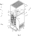
- the device 10 for purifying a gaseous medium laden with particles forming the subject of the embodiment of the figures 1 to 3 is a free-standing device, which can be mounted on wheels. It has an overall rectangular parallelepiped configuration.
- This purification device 10 generally comprises an electrostatic filtration chamber 11 and suction means 12 downstream of this electrostatic filtration chamber, to extract from the chamber the gaseous medium stripped of its particles.
- this electrostatic filtration chamber 11 is, here, interposed between an inlet compartment 13 through which the gaseous medium laden with particles enters the device and more particularly into the electrostatic filtration chamber 11 and an outlet compartment 14, thanks to which the suction means 12 are housed and by which the gaseous medium stripped of its particles is discharged into the surrounding environment.
- the inlet compartment 13 comprises a frame 15 carried by a bottom 16 and formed of four walls assembled at right angles, one of which, 17, is perforated to allow the gaseous medium to enter the device, here from below the electrostatic filtration chamber 11.
- the gaseous medium laden with particles thus enters the purification device 10, in a direction substantially perpendicular to that of flow in the filtration chamber 11.
- a pre-filter 18 intended to retain large particles. This is, for example, a metal knit or stretched metal filter.
- the outlet compartment 14 for the gaseous medium stripped of its particles comprises a box 19 in the shape of a rectangular parallelepiped, the upper wall 20 of which is perforated to allow this gaseous medium stripped of its particles to pass. .
- suction means 12 which are here in the form of a fan, are mounted in this box 19, at the level of the face of the latter opposite the perforated wall 20.
- the gaseous medium thus flows horizontally in the inlet box 15 then vertically to the outlet of the purification device 10.
- the suction means 12 are arranged directly at the outlet of the electrostatic filtration chamber 11 and are in fluid communication therewith to suck in the gaseous medium.
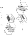
- This electrostatic filtration chamber 11 comprises, here, two supports 21 of emissive structures arranged in the passage formed by the electrostatic filtration chamber 11 between an inlet therein (after the prefilter 18) and an outlet thereof (just before the suction means 12).
- collecting structures 22 designed to trap the particles contained in the gaseous medium charged with particles.
- Each support 21 of emissive structures comprises, more precisely, a plurality of emissive structures 23 arranged in the passage, one after the other, between the inlet and the outlet of the electrostatic filtration chamber 11.
- Each emissive structure 23 is in the form of a plate, preferably a blade, here five in number per support 21, designed to force the gaseous medium laden with particles to flow in the vicinity of the collecting structures 22.
- Each blade 23 also comprises, at its periphery, points 26 directed towards the collecting structures 22.
- Each support 21 comprises two U-sections 27 assembled, parallel to each other and back to back, by four spacers 28 each welded to a corner of the U-section 27. It should be noted in this respect that the fourth spacer 28 is not visible in the figures.
- Each blade 23 comprises, for its mounting on this support 21, a rod 29 welded to each of two opposite mounting edges 30 which extend generally perpendicular to the edges of the blades 23 provided with the points 26.
- the U-sections 27 are provided, for receiving the rods 29, with passage openings 31 for these rods.
- the maintenance in position on the support 21 of each of the blades is obtained, in the case of the present embodiment, by means of the interposition of a nested insulator 32, by complementarity of shapes (of square section), in an opening 31 and receiving, itself, a rod 29 of the blade 23.
- Each rod 29 is, to do this, threaded and engaged in a central cylindrical hole of the insulator 32 and fixed by a nut (not visible in the figures and housed in a passage hole 36 of square section preceding this cylindrical hole in the insulator and ending before this last hole with a bearing surface for the nut), so that each blade is mounted with possibility of angular orientation in the electrostatic filtration chamber 11.
- the insulator can also be protected by means of a bell and a counter-bell or deflectors, in the manner of what is described in the application for patent cited above ( WO 01/19525 ). This makes it possible in particular to avoid electrical bridges.
- Each blade 23 forming an emissive structure is, here, brought to a cathodic voltage of the order of 10 kV by a circuit supplying a high voltage 33, housed in a control box 34 mounted, within the framework of this embodiment, in box 19.
- each collector structure 22 comprises, in the context of the present embodiment, a metal knit in the form of a plate brought, here, to an anode voltage of the order of 5 kV, being connected to a circuit 35 providing a high voltage, which is also housed in the control box 34.
- the collector plates 22 can be mounted in a frame by means of rods passing through openings made in this frame and the interposition of insulators, in a manner similar to that provided for the blades 23 on their support 21. Therefore, this has not been shown in the figures, for the sake of simplification.
- connection to the circuit 35 can be obtained, for example, with a leaf spring integral with the upper box 19 and in contact with a rod of the plate 22.
- the implementation of one or more of these blades can also allow to maintain the plate in position within the device and its placement and removal therefrom.
- the purification device in accordance with the present invention thus proves to be particularly flexible, in particular thanks to the mounting of the blades 23 on the supports 21, one independently of the other (and electrically isolated from each other on their support).
- This makes it possible in particular to orient each of the blades as desired, in particular to produce ozone having a germicidal effect on microorganisms of the virus and bacteria type.
- This production of ozone can be obtained by orienting the blades 23 perpendicular to the collector plates 22, while an orientation different from the perpendicular (the tips of the collector structures 22 are moved away) will stop or reduce this production of ozone.
- the blades 23 are always oriented so as to form a non-zero angle with the plane of the collector plates 22 which extend parallel to one another, the blades 23 being themselves aligned according to a parallel alignment to these same planes.
- edges of the blades 23 provided with the points 26, extend to the vicinity of the collector plates 22, leaving only a space remaining avoiding the formation of arcs in a position in which the blades 23 are extend perpendicularly to these collector plates 22 or, in practice, a space of the order of one millimeter for 1000V of voltage applied to the blade 23 corresponding.
- negative ions produced by the ionization taking place in the electrostatic filtration chamber are also of interest in terms of the therapeutic effects that they can generate.
- a door 37 is, moreover, provided to isolate the side collector plates 22 from the surrounding environment, while being able to access them to remove them from the purification device 10 with a view to cleaning them.
- This device also proves to be easy to manufacture, for example from cutting and, where appropriate, bending of stainless steel plates.
- the device can operate vertically, as seen on the figures 1 to 3 , or horizontally.
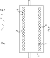
- emissive structures 23′ here plates, extending side by side, preferably parallel to one another, in the passage, with an arrangement in staggered from one row to the other.
- a single support 21′ is moreover provided in the context of this embodiment to carry these emissive structures 23′.
- the spikes 26" do not protrude from the periphery of each of the plates, but are formed inside the corresponding plate, by means of a longitudinal cut made therein in the vicinity of each of its longitudinal edges.
- a cutout forming two rows of rounded notches 25", facing each other and forming between them the points 26" directed towards the collecting structures.
- Each cutout is further formed so that the 26" tips of the two rows are staggered.
- the device according to the invention could comprise a UV radiation lamp arranged upstream of the entrance to the electrostatic filtration chamber 11 (for example in the box 15) to attract and kill insects, such as mosquitoes .
- a finishing filter for example based on activated carbon, in metal knit or stretched metal, can also be implemented between the electrostatic filtration chamber 11 and the suction means 12.
- Each collector structure can also comprise one or a succession of stretched metal plates instead of the metal knit or even be made from an alternation of metal knit and stretched metal plates.
- voltages can also be considered for the emitting and collecting structures.
- it can be envisaged to bring, in a succession of stretched metal plates forming a collector structure, one plate out of two to a voltage of the order of 5 kV and to ground the following one.
- the voltages are chosen to be between 10 and 50 kV.
- the circuit supplying a high voltage will of course supply a positive or negative high voltage.
- Another possibility could be to bring one out of two emissive structures to a positive high voltage and the other to a negative high voltage, while the collecting structures would be grounded or a positive high voltage.
- a frame made from sections, such as angle irons, can complete the device, for example for its mounting on wheels or the positioning of the central collecting plates on rails in the form of U to facilitate their sliding.
- each blade may, to increase the turbulence at the level of the aspirated flow, be twisted.
Landscapes
- Electrostatic Separation (AREA)
Claims (12)
- Vorrichtung zur Reinigung (10) eines mit Teilchen beladenen gasförmigen Mediums, die eine elektrostatische Filterkammer (11) umfasst, welche einen Durchlass für das teilchenbeladene gasförmige Medium aufweist, der sich zwischen einem Einlass dieses Mediums in die Kammer (11) und einem Auslass aus dieser letzteren erstreckt; eine Vielzahl von Emissionsstrukturen (23), die eine neben der anderen zwischen dem Einlass und dem Auslass der Kammer (11) in dem Durchlass angeordnet sind; und beiderseits dieser Emissionsstrukturen (23) Sammelstrukturen (22) in Form von Platten, um die Teilchen zu sammeln; wobei sich jede Emissionsstruktur (23) in Form einer Platte darstellt, die an ihrem Umfang Spitzen (26) umfasst, die zu den Sammelstrukturen (22) gerichtet sind;
dadurch gekennzeichnet, dass jede Platte der Emissionsstrukturen (23) so konzipiert ist, dass sie das teilchenbeladene gasförmige Medium dazu zwingt, in der Nähe der Sammelstrukturen (23) zu strömen; wobei jede Sammelstruktur (22), um die in dem teilchenbeladenen gasförmigen Medium enthaltenen Teilchen zu fangen, ein Metallgewebe und/oder eine Abfolge von Platten aus Streckmetall umfasst; und die Vorrichtung (10) weiter Saugmittel (12) umfasst, die fluidisch mit dem Auslass der Kammer (11) verbunden sind, um das von seinen Teilchen befreite gasförmige Medium aus der Kammer (11) abzuziehen. - Vorrichtung (10) nach Anspruch 1, wobei mindestens eine der Emissionsstrukturen (23) ausrichtbar in der elektrostatischen Filterkammer (11) montiert ist.
- Vorrichtung (10) nach Anspruch 1 oder 2, wobei sich jede Platte der Emissionsstrukturen (23) in Form einer Lamelle darstellt, die verdreht sein kann.
- Vorrichtung (10) nach einem der Ansprüche 1 bis 3, wobei jede Platte der Emissionsstrukturen (23) beiderseits einer zentralen Ablenkfläche (24) Einbuchtungen (25) aufweist, die zwischen sich die Spitzen (26) bilden.
- Vorrichtung (10) nach Anspruch 4, wobei die Spitzen (26) entlang von zwei gegenüberliegenden Rändern jeder Platte der Emissionsstrukturen (23) versetzt angeordnet sind.
- Vorrichtung (10) nach Anspruch 4 oder 5, wobei sich die Ränder der Platten der Emissionsstrukturen (23), die keine Spitzen (26) aufweisen, bis in die Nähe der Sammelstrukturen (22) erstrecken, wobei an einer Stelle, an der sich die Platten der Emissionsstrukturen (23) senkrecht zu den Sammelstrukturen (22) parallel zueinander erstrecken, nur ein Raum belassen wird, bei dem die Bildung von Bögen vermieden wird.
- Vorrichtung (10) nach einem der Ansprüche 1 bis 6, wobei jede Platte der Emissionsstrukturen (23) an jedem von zwei gegenüberliegenden Montagerändern einen vorstehenden Schaft (29) für die Montage der Platte der Emissionsstrukturen (23) an einer Halterung (21) umfasst.
- Vorrichtung (10) nach Anspruch 7, wobei sich die Halterung (21) in Form eines Rahmens darstellt, der für die Aufnahme jedes Schafts (29) mit einer Durchlassöffnung für diesen versehen ist.
- Vorrichtung (10) nach einem der Ansprüche 1 bis 8, wobei jede Emissionsstruktur (23) auf hohe Spannung, vorzugsweise auf eine Spannung in der Größenordnung von 10 kV, gebracht wird.
- Vorrichtung (10) nach einem der Ansprüche 1 bis 9, wobei jede Sammelstruktur (22) auf hohe Spannung, vorzugsweise auf eine Spannung in der Größenordnung von 5 kV, gebracht wird.
- Vorrichtung (10) nach einem der Ansprüche 1 bis 10, wobei die Emissionsstrukturen (23) in einer zu den Sammelstrukturen (22) parallelen Ausrichtung ausgerichtet sind.
- Vorrichtung (10) nach einem der Ansprüche 1 bis 11, wobei jede Sammelstruktur (22) die Form eines rechteckigen Parallelepipeds aufweist.
Applications Claiming Priority (2)
| Application Number | Priority Date | Filing Date | Title |
|---|---|---|---|
| FR1453065A FR3019474B1 (fr) | 2014-04-07 | 2014-04-07 | Dispositif de filtration |
| PCT/FR2015/050876 WO2015155449A1 (fr) | 2014-04-07 | 2015-04-03 | Dispositif de filtration |
Publications (2)
| Publication Number | Publication Date |
|---|---|
| EP3129151A1 EP3129151A1 (de) | 2017-02-15 |
| EP3129151B1 true EP3129151B1 (de) | 2022-11-23 |
Family
ID=51352545
Family Applications (1)
| Application Number | Title | Priority Date | Filing Date |
|---|---|---|---|
| EP15719801.1A Active EP3129151B1 (de) | 2014-04-07 | 2015-04-03 | Filtervorrichtung |
Country Status (3)
| Country | Link |
|---|---|
| EP (1) | EP3129151B1 (de) |
| FR (1) | FR3019474B1 (de) |
| WO (1) | WO2015155449A1 (de) |
Citations (2)
| Publication number | Priority date | Publication date | Assignee | Title |
|---|---|---|---|---|
| JPH0263560A (ja) * | 1988-08-30 | 1990-03-02 | Mitsubishi Heavy Ind Ltd | 除じん装置 |
| WO2014204310A1 (en) * | 2013-06-19 | 2014-12-24 | Virus Free Air B.V. | Gas flow cleaning device |
Family Cites Families (6)
| Publication number | Priority date | Publication date | Assignee | Title |
|---|---|---|---|---|
| JPS58119355A (ja) * | 1981-12-30 | 1983-07-15 | Ono Kagaku Kikai Kk | 電気集じん装置 |
| JP3358008B2 (ja) * | 1994-01-31 | 2002-12-16 | 株式会社エルデック | 電気集塵装置 |
| FR2798303B1 (fr) | 1999-09-14 | 2001-11-09 | Daniel Teboul | Dispositif de traitement d'un milieu gazeux, en particulier des gaz d'echappement d'un moteur a combustion interne, et vehicule equipe d'un tel dispositif |
| CN1791468B (zh) * | 2003-08-29 | 2012-02-08 | 三菱重工业株式会社 | 集尘装置 |
| CN103025434A (zh) * | 2010-06-02 | 2013-04-03 | 三菱重工机电系统株式会社 | 集尘装置的运行方法以及集尘装置 |
| KR101199552B1 (ko) * | 2011-11-04 | 2012-11-12 | 서울특별시도시철도공사 | 허니컴대전부를 갖는 유도전압 전기집진장치 |
-
2014
- 2014-04-07 FR FR1453065A patent/FR3019474B1/fr not_active Expired - Fee Related
-
2015
- 2015-04-03 WO PCT/FR2015/050876 patent/WO2015155449A1/fr not_active Ceased
- 2015-04-03 EP EP15719801.1A patent/EP3129151B1/de active Active
Patent Citations (2)
| Publication number | Priority date | Publication date | Assignee | Title |
|---|---|---|---|---|
| JPH0263560A (ja) * | 1988-08-30 | 1990-03-02 | Mitsubishi Heavy Ind Ltd | 除じん装置 |
| WO2014204310A1 (en) * | 2013-06-19 | 2014-12-24 | Virus Free Air B.V. | Gas flow cleaning device |
Also Published As
| Publication number | Publication date |
|---|---|
| FR3019474B1 (fr) | 2019-08-02 |
| FR3019474A1 (fr) | 2015-10-09 |
| WO2015155449A1 (fr) | 2015-10-15 |
| EP3129151A1 (de) | 2017-02-15 |
Similar Documents
| Publication | Publication Date | Title |
|---|---|---|
| EP2564933B1 (de) | Elektrostatische Sammelvorrichtung von Partikeln suspendiert in einem gasförmigen Medium | |
| CN107427839B (zh) | 用于分离污染物的设备和方法 | |
| RU2613654C1 (ru) | Установка для фильтрации микрочастиц, содержащихся в газообразных продуктах сгорания и/или отработавших газах, и соответствующий выпускной контур | |
| WO2009104411A1 (ja) | 集塵装置 | |
| EP3328548B1 (de) | Verfahren und vorrichtung zum selektiven sammeln von aerosolpartikeln nach partikelgrösse | |
| US10828646B2 (en) | Electrostatic air filter | |
| US20150075379A1 (en) | Filtration assembly | |
| FR2655882A1 (fr) | Dispositif pour epurer des gaz. | |
| KR20110135899A (ko) | 멀티크로스핀 이오나이저를 이용한 유도전압 전기집진장치 | |
| CN102209591A (zh) | 集尘装置 | |
| JP2009125653A (ja) | 空気浄化装置 | |
| EP3129151B1 (de) | Filtervorrichtung | |
| JP2010022949A (ja) | 排ガス処理装置 | |
| KR101180035B1 (ko) | 멀티크로스핀 이오나이저를 이용한 유도전압 전기집진장치 | |
| WO2008107598A1 (fr) | Dispositif de filtre electrostatique pour la capture et la destruction de particules de suie contenues dans les gaz d'echappement d'un moteur a combustion | |
| EP2566526A1 (de) | Einheit zur luftreinigung mittels fotokatalyse | |
| EP2954954B1 (de) | Luftfilteranordnung | |
| US20240299954A1 (en) | High efficiency negative ionisation cell for fine particles, ultrafine particles and nanoparticles present at high and ultra-high density in fumes, in vehicle exhaust gases and in the air | |
| JP2010240578A (ja) | 集塵セル及びこれを用いたエアクリーナ | |
| EP0744996B1 (de) | Zyklon-austauscher zur reinigung und entgiftung der luft | |
| FR2717711A1 (fr) | Electrofiltre épurateur ioniseur en milieu gazeux, de grande puissance, à configuration de champ électrique de haute densité. | |
| FR2623424A1 (fr) | Dispositif et procede de filtrage electrostatique a filtre perpendiculaire a l'ecoulement de fluide gazeux, notamment de l'air | |
| JP2013086047A (ja) | イオン捕捉シート、イオン捕捉モジュールおよびクリーンエア供給装置 | |
| JP5561995B2 (ja) | 浮遊物濾過補足装置 | |
| FR3135900A1 (fr) | Dispositif ionique de traitement de l’air |
Legal Events
| Date | Code | Title | Description |
|---|---|---|---|
| STAA | Information on the status of an ep patent application or granted ep patent |
Free format text: STATUS: THE INTERNATIONAL PUBLICATION HAS BEEN MADE |
|
| PUAI | Public reference made under article 153(3) epc to a published international application that has entered the european phase |
Free format text: ORIGINAL CODE: 0009012 |
|
| STAA | Information on the status of an ep patent application or granted ep patent |
Free format text: STATUS: REQUEST FOR EXAMINATION WAS MADE |
|
| 17P | Request for examination filed |
Effective date: 20161107 |
|
| AK | Designated contracting states |
Kind code of ref document: A1 Designated state(s): AL AT BE BG CH CY CZ DE DK EE ES FI FR GB GR HR HU IE IS IT LI LT LU LV MC MK MT NL NO PL PT RO RS SE SI SK SM TR |
|
| AX | Request for extension of the european patent |
Extension state: BA ME |
|
| DAV | Request for validation of the european patent (deleted) | ||
| DAX | Request for extension of the european patent (deleted) | ||
| STAA | Information on the status of an ep patent application or granted ep patent |
Free format text: STATUS: EXAMINATION IS IN PROGRESS |
|
| 17Q | First examination report despatched |
Effective date: 20180525 |
|
| GRAP | Despatch of communication of intention to grant a patent |
Free format text: ORIGINAL CODE: EPIDOSNIGR1 |
|
| STAA | Information on the status of an ep patent application or granted ep patent |
Free format text: STATUS: GRANT OF PATENT IS INTENDED |
|
| RIC1 | Information provided on ipc code assigned before grant |
Ipc: B03C 3/47 20060101ALI20211206BHEP Ipc: B03C 3/41 20060101ALI20211206BHEP Ipc: B03C 3/36 20060101ALI20211206BHEP Ipc: B03C 3/011 20060101ALI20211206BHEP Ipc: B03C 3/155 20060101ALI20211206BHEP Ipc: B03C 3/09 20060101ALI20211206BHEP Ipc: B03C 3/08 20060101ALI20211206BHEP Ipc: B03C 3/32 20060101AFI20211206BHEP |
|
| INTG | Intention to grant announced |
Effective date: 20211223 |
|
| GRAS | Grant fee paid |
Free format text: ORIGINAL CODE: EPIDOSNIGR3 |
|
| GRAA | (expected) grant |
Free format text: ORIGINAL CODE: 0009210 |
|
| STAA | Information on the status of an ep patent application or granted ep patent |
Free format text: STATUS: THE PATENT HAS BEEN GRANTED |
|
| AK | Designated contracting states |
Kind code of ref document: B1 Designated state(s): AL AT BE BG CH CY CZ DE DK EE ES FI FR GB GR HR HU IE IS IT LI LT LU LV MC MK MT NL NO PL PT RO RS SE SI SK SM TR |
|
| REG | Reference to a national code |
Ref country code: GB Ref legal event code: FG4D Free format text: NOT ENGLISH |
|
| REG | Reference to a national code |
Ref country code: CH Ref legal event code: EP |
|
| REG | Reference to a national code |
Ref country code: AT Ref legal event code: REF Ref document number: 1532813 Country of ref document: AT Kind code of ref document: T Effective date: 20221215 Ref country code: DE Ref legal event code: R096 Ref document number: 602015081670 Country of ref document: DE |
|
| REG | Reference to a national code |
Ref country code: IE Ref legal event code: FG4D Free format text: LANGUAGE OF EP DOCUMENT: FRENCH |
|
| REG | Reference to a national code |
Ref country code: LT Ref legal event code: MG9D |
|
| REG | Reference to a national code |
Ref country code: NL Ref legal event code: MP Effective date: 20221123 |
|
| REG | Reference to a national code |
Ref country code: AT Ref legal event code: MK05 Ref document number: 1532813 Country of ref document: AT Kind code of ref document: T Effective date: 20221123 |
|
| PG25 | Lapsed in a contracting state [announced via postgrant information from national office to epo] |
Ref country code: SE Free format text: LAPSE BECAUSE OF FAILURE TO SUBMIT A TRANSLATION OF THE DESCRIPTION OR TO PAY THE FEE WITHIN THE PRESCRIBED TIME-LIMIT Effective date: 20221123 Ref country code: PT Free format text: LAPSE BECAUSE OF FAILURE TO SUBMIT A TRANSLATION OF THE DESCRIPTION OR TO PAY THE FEE WITHIN THE PRESCRIBED TIME-LIMIT Effective date: 20230323 Ref country code: NO Free format text: LAPSE BECAUSE OF FAILURE TO SUBMIT A TRANSLATION OF THE DESCRIPTION OR TO PAY THE FEE WITHIN THE PRESCRIBED TIME-LIMIT Effective date: 20230223 Ref country code: LT Free format text: LAPSE BECAUSE OF FAILURE TO SUBMIT A TRANSLATION OF THE DESCRIPTION OR TO PAY THE FEE WITHIN THE PRESCRIBED TIME-LIMIT Effective date: 20221123 Ref country code: FI Free format text: LAPSE BECAUSE OF FAILURE TO SUBMIT A TRANSLATION OF THE DESCRIPTION OR TO PAY THE FEE WITHIN THE PRESCRIBED TIME-LIMIT Effective date: 20221123 Ref country code: ES Free format text: LAPSE BECAUSE OF FAILURE TO SUBMIT A TRANSLATION OF THE DESCRIPTION OR TO PAY THE FEE WITHIN THE PRESCRIBED TIME-LIMIT Effective date: 20221123 Ref country code: AT Free format text: LAPSE BECAUSE OF FAILURE TO SUBMIT A TRANSLATION OF THE DESCRIPTION OR TO PAY THE FEE WITHIN THE PRESCRIBED TIME-LIMIT Effective date: 20221123 |
|
| PG25 | Lapsed in a contracting state [announced via postgrant information from national office to epo] |
Ref country code: RS Free format text: LAPSE BECAUSE OF FAILURE TO SUBMIT A TRANSLATION OF THE DESCRIPTION OR TO PAY THE FEE WITHIN THE PRESCRIBED TIME-LIMIT Effective date: 20221123 Ref country code: PL Free format text: LAPSE BECAUSE OF FAILURE TO SUBMIT A TRANSLATION OF THE DESCRIPTION OR TO PAY THE FEE WITHIN THE PRESCRIBED TIME-LIMIT Effective date: 20221123 Ref country code: LV Free format text: LAPSE BECAUSE OF FAILURE TO SUBMIT A TRANSLATION OF THE DESCRIPTION OR TO PAY THE FEE WITHIN THE PRESCRIBED TIME-LIMIT Effective date: 20221123 Ref country code: IS Free format text: LAPSE BECAUSE OF FAILURE TO SUBMIT A TRANSLATION OF THE DESCRIPTION OR TO PAY THE FEE WITHIN THE PRESCRIBED TIME-LIMIT Effective date: 20230323 Ref country code: HR Free format text: LAPSE BECAUSE OF FAILURE TO SUBMIT A TRANSLATION OF THE DESCRIPTION OR TO PAY THE FEE WITHIN THE PRESCRIBED TIME-LIMIT Effective date: 20221123 Ref country code: GR Free format text: LAPSE BECAUSE OF FAILURE TO SUBMIT A TRANSLATION OF THE DESCRIPTION OR TO PAY THE FEE WITHIN THE PRESCRIBED TIME-LIMIT Effective date: 20230224 |
|
| PG25 | Lapsed in a contracting state [announced via postgrant information from national office to epo] |
Ref country code: NL Free format text: LAPSE BECAUSE OF FAILURE TO SUBMIT A TRANSLATION OF THE DESCRIPTION OR TO PAY THE FEE WITHIN THE PRESCRIBED TIME-LIMIT Effective date: 20221123 |
|
| PG25 | Lapsed in a contracting state [announced via postgrant information from national office to epo] |
Ref country code: SM Free format text: LAPSE BECAUSE OF FAILURE TO SUBMIT A TRANSLATION OF THE DESCRIPTION OR TO PAY THE FEE WITHIN THE PRESCRIBED TIME-LIMIT Effective date: 20221123 Ref country code: RO Free format text: LAPSE BECAUSE OF FAILURE TO SUBMIT A TRANSLATION OF THE DESCRIPTION OR TO PAY THE FEE WITHIN THE PRESCRIBED TIME-LIMIT Effective date: 20221123 Ref country code: EE Free format text: LAPSE BECAUSE OF FAILURE TO SUBMIT A TRANSLATION OF THE DESCRIPTION OR TO PAY THE FEE WITHIN THE PRESCRIBED TIME-LIMIT Effective date: 20221123 Ref country code: DK Free format text: LAPSE BECAUSE OF FAILURE TO SUBMIT A TRANSLATION OF THE DESCRIPTION OR TO PAY THE FEE WITHIN THE PRESCRIBED TIME-LIMIT Effective date: 20221123 Ref country code: CZ Free format text: LAPSE BECAUSE OF FAILURE TO SUBMIT A TRANSLATION OF THE DESCRIPTION OR TO PAY THE FEE WITHIN THE PRESCRIBED TIME-LIMIT Effective date: 20221123 |
|
| REG | Reference to a national code |
Ref country code: DE Ref legal event code: R097 Ref document number: 602015081670 Country of ref document: DE |
|
| PG25 | Lapsed in a contracting state [announced via postgrant information from national office to epo] |
Ref country code: SK Free format text: LAPSE BECAUSE OF FAILURE TO SUBMIT A TRANSLATION OF THE DESCRIPTION OR TO PAY THE FEE WITHIN THE PRESCRIBED TIME-LIMIT Effective date: 20221123 Ref country code: AL Free format text: LAPSE BECAUSE OF FAILURE TO SUBMIT A TRANSLATION OF THE DESCRIPTION OR TO PAY THE FEE WITHIN THE PRESCRIBED TIME-LIMIT Effective date: 20221123 |
|
| PLBE | No opposition filed within time limit |
Free format text: ORIGINAL CODE: 0009261 |
|
| STAA | Information on the status of an ep patent application or granted ep patent |
Free format text: STATUS: NO OPPOSITION FILED WITHIN TIME LIMIT |
|
| 26N | No opposition filed |
Effective date: 20230824 |
|
| REG | Reference to a national code |
Ref country code: DE Ref legal event code: R119 Ref document number: 602015081670 Country of ref document: DE |
|
| PG25 | Lapsed in a contracting state [announced via postgrant information from national office to epo] |
Ref country code: SI Free format text: LAPSE BECAUSE OF FAILURE TO SUBMIT A TRANSLATION OF THE DESCRIPTION OR TO PAY THE FEE WITHIN THE PRESCRIBED TIME-LIMIT Effective date: 20221123 |
|
| REG | Reference to a national code |
Ref country code: CH Ref legal event code: PL |
|
| GBPC | Gb: european patent ceased through non-payment of renewal fee |
Effective date: 20230403 |
|
| PG25 | Lapsed in a contracting state [announced via postgrant information from national office to epo] |
Ref country code: LU Free format text: LAPSE BECAUSE OF NON-PAYMENT OF DUE FEES Effective date: 20230403 |
|
| REG | Reference to a national code |
Ref country code: BE Ref legal event code: MM Effective date: 20230430 |
|
| PG25 | Lapsed in a contracting state [announced via postgrant information from national office to epo] |
Ref country code: MC Free format text: LAPSE BECAUSE OF FAILURE TO SUBMIT A TRANSLATION OF THE DESCRIPTION OR TO PAY THE FEE WITHIN THE PRESCRIBED TIME-LIMIT Effective date: 20221123 |
|
| PG25 | Lapsed in a contracting state [announced via postgrant information from national office to epo] |
Ref country code: GB Free format text: LAPSE BECAUSE OF NON-PAYMENT OF DUE FEES Effective date: 20230403 |
|
| PG25 | Lapsed in a contracting state [announced via postgrant information from national office to epo] |
Ref country code: MC Free format text: LAPSE BECAUSE OF FAILURE TO SUBMIT A TRANSLATION OF THE DESCRIPTION OR TO PAY THE FEE WITHIN THE PRESCRIBED TIME-LIMIT Effective date: 20221123 Ref country code: LI Free format text: LAPSE BECAUSE OF NON-PAYMENT OF DUE FEES Effective date: 20230430 Ref country code: GB Free format text: LAPSE BECAUSE OF NON-PAYMENT OF DUE FEES Effective date: 20230403 Ref country code: FR Free format text: LAPSE BECAUSE OF NON-PAYMENT OF DUE FEES Effective date: 20230430 Ref country code: DE Free format text: LAPSE BECAUSE OF NON-PAYMENT OF DUE FEES Effective date: 20231103 Ref country code: CH Free format text: LAPSE BECAUSE OF NON-PAYMENT OF DUE FEES Effective date: 20230430 |
|
| REG | Reference to a national code |
Ref country code: IE Ref legal event code: MM4A |
|
| PG25 | Lapsed in a contracting state [announced via postgrant information from national office to epo] |
Ref country code: BE Free format text: LAPSE BECAUSE OF NON-PAYMENT OF DUE FEES Effective date: 20230430 |
|
| PG25 | Lapsed in a contracting state [announced via postgrant information from national office to epo] |
Ref country code: IE Free format text: LAPSE BECAUSE OF NON-PAYMENT OF DUE FEES Effective date: 20230403 |
|
| PG25 | Lapsed in a contracting state [announced via postgrant information from national office to epo] |
Ref country code: IE Free format text: LAPSE BECAUSE OF NON-PAYMENT OF DUE FEES Effective date: 20230403 |
|
| PG25 | Lapsed in a contracting state [announced via postgrant information from national office to epo] |
Ref country code: IT Free format text: LAPSE BECAUSE OF FAILURE TO SUBMIT A TRANSLATION OF THE DESCRIPTION OR TO PAY THE FEE WITHIN THE PRESCRIBED TIME-LIMIT Effective date: 20221123 |
|
| PG25 | Lapsed in a contracting state [announced via postgrant information from national office to epo] |
Ref country code: FR Free format text: LAPSE BECAUSE OF NON-PAYMENT OF DUE FEES Effective date: 20230430 |
|
| PGRI | Patent reinstated in contracting state [announced from national office to epo] |
Ref country code: FR Effective date: 20240613 |
|
| PGFP | Annual fee paid to national office [announced via postgrant information from national office to epo] |
Ref country code: FR Payment date: 20240830 Year of fee payment: 10 |
|
| PG25 | Lapsed in a contracting state [announced via postgrant information from national office to epo] |
Ref country code: BG Free format text: LAPSE BECAUSE OF FAILURE TO SUBMIT A TRANSLATION OF THE DESCRIPTION OR TO PAY THE FEE WITHIN THE PRESCRIBED TIME-LIMIT Effective date: 20221123 |
|
| PG25 | Lapsed in a contracting state [announced via postgrant information from national office to epo] |
Ref country code: BG Free format text: LAPSE BECAUSE OF FAILURE TO SUBMIT A TRANSLATION OF THE DESCRIPTION OR TO PAY THE FEE WITHIN THE PRESCRIBED TIME-LIMIT Effective date: 20221123 |
|
| PG25 | Lapsed in a contracting state [announced via postgrant information from national office to epo] |
Ref country code: CY Free format text: LAPSE BECAUSE OF FAILURE TO SUBMIT A TRANSLATION OF THE DESCRIPTION OR TO PAY THE FEE WITHIN THE PRESCRIBED TIME-LIMIT; INVALID AB INITIO Effective date: 20150403 |
|
| PG25 | Lapsed in a contracting state [announced via postgrant information from national office to epo] |
Ref country code: HU Free format text: LAPSE BECAUSE OF FAILURE TO SUBMIT A TRANSLATION OF THE DESCRIPTION OR TO PAY THE FEE WITHIN THE PRESCRIBED TIME-LIMIT; INVALID AB INITIO Effective date: 20150403 |
|
| PG25 | Lapsed in a contracting state [announced via postgrant information from national office to epo] |
Ref country code: TR Free format text: LAPSE BECAUSE OF FAILURE TO SUBMIT A TRANSLATION OF THE DESCRIPTION OR TO PAY THE FEE WITHIN THE PRESCRIBED TIME-LIMIT Effective date: 20221123 |
|
| PG25 | Lapsed in a contracting state [announced via postgrant information from national office to epo] |
Ref country code: FR Free format text: LAPSE BECAUSE OF NON-PAYMENT OF DUE FEES Effective date: 20250430 |