EP3128283A1 - Protective element for protection against ballistic missiles, and military vehicle - Google Patents
Protective element for protection against ballistic missiles, and military vehicle Download PDFInfo
- Publication number
- EP3128283A1 EP3128283A1 EP16190363.8A EP16190363A EP3128283A1 EP 3128283 A1 EP3128283 A1 EP 3128283A1 EP 16190363 A EP16190363 A EP 16190363A EP 3128283 A1 EP3128283 A1 EP 3128283A1
- Authority
- EP
- European Patent Office
- Prior art keywords
- protective element
- holes
- plate
- perforated
- armor
- Prior art date
- Legal status (The legal status is an assumption and is not a legal conclusion. Google has not performed a legal analysis and makes no representation as to the accuracy of the status listed.)
- Granted
Links
Images


Classifications
-
- F—MECHANICAL ENGINEERING; LIGHTING; HEATING; WEAPONS; BLASTING
- F41—WEAPONS
- F41H—ARMOUR; ARMOURED TURRETS; ARMOURED OR ARMED VEHICLES; MEANS OF ATTACK OR DEFENCE, e.g. CAMOUFLAGE, IN GENERAL
- F41H5/00—Armour; Armour plates
- F41H5/02—Plate construction
- F41H5/023—Armour plate, or auxiliary armour plate mounted at a distance of the main armour plate, having cavities at its outer impact surface, or holes, for deflecting the projectile
Definitions
- the invention relates to a protective element for protection against ballistic projectiles with an armor plate and a military vehicle with such a protective element.
- Protective elements are used in military applications on vehicles and other facilities, such. As buildings and weapons used to ward off dangers of various kinds. For protection against bullet-impact projectiles, such as projectile-accelerated projectiles or projectile-forming charges (explosively formed projectiles, EFP), protective elements with an armor plate can be used.
- the armor plate of such protective elements is usually made solid and has an increased resistance to ballistic bullets.
- the invention has the object to reduce the weight of the protective element, without adversely affecting its protective effect against ballistic projectiles.
- the object is achieved in that the armor plate is formed as a plurality of holes having hole plate.
- the material of the armor plate is removed so that the perforated armor plate has a reduced weight compared to a solid armor plate.
- the weight of the entire protective element can thus be reduced by the perforated plate.
- the protective element according to the invention can have a level of protection that is comparable to the level of protection of a protective element with a solid armor plate.
- a projectile striking the perforated plate can be broken up at the holes and / or divided into several parts, so that its penetrating power can be reduced. Parts of the projectile can pass through the holes of the perforated plate and thereby tear the projectile.
- impacting projectiles can be deflected at the edges and / or inner walls of the holes.
- This effect of the holes also has a positive effect on the protective effect, since deflected projectiles can have a reduced kinetic energy and thus can be repelled more easily.
- the invention can provide a reduced weight protective element whose protective effect against ballistic projectiles through the holes is not adversely affected.
- the holes of the perforated plate may be formed as the armor plate completely penetrating through holes. But it is also possible to form the holes as blind holes, which penetrate the armor plate only partially.
- the material of the armor plate may have a thickness which is at most 50% of the thickness of the material surrounding the holes, preferably 10% of the thickness of the material surrounding the holes, more preferably at most 5% corresponds to the thickness of the material surrounding the holes.
- the holes in the perforated plate are arranged distributed in a grid pattern, so that an area is formed in which impinging projectiles can be broken up, divided and / or deflected.
- a hole pattern may be formed from a plurality of holes that are equal in size and / or arranged at equal orthogonal distances from each other. Through the hole pattern, a regularly perforated surface of the perforated plate can be formed, which has a uniform level of protection.
- the breadboard can extend over the entire surface of the armor plate facing the bullet threat, providing full-scale ballistic bullet protection.
- the size of the holes is chosen to be smaller than the caliber of the impacting projectiles, so that a projectile can not penetrate a hole without being broken up or broken up. Effective protection against bullets of caliber 7.62 mm can be achieved, for example, if the holes have a diameter of 7 mm.
- the holes of the perforated plate can basically have any cross-sectional area.
- the holes are formed with a circular cross-sectional area, so that they can be introduced as cylindrical bores by a drilling tool in the armor plate.
- the width of the cross-sectional area, in particular the diameter, of the holes is greater than the distance between the holes, so that the impacting projectiles can hit with an increased probability in the region of a hole on the perforated plate.
- the ratio of the distance between the holes to the width of the cross-sectional area of the holes can be in the range greater than 0.5, preferably greater than 0.55, particularly preferably greater than 0.6. Bullets with the caliber 7.62 mm can z. B. are effectively fended off when the holes have a diameter of 7 mm and are 4 mm apart.
- the protective element can have a plurality of perforated plates arranged in a layered manner, so that such projectiles which can not be completely decelerated in the first perforated plate can impinge on a second perforated plate arranged behind the first perforated plate.
- a projectile penetrating into the protective element can be repeatedly divided and / or deflected at the layered perforated plates.
- the perforated plates may be arranged in several parallel layers or oriented obliquely to each other. Between the individual perforated plates, a free space can be provided, which projectile fragments can penetrate unhindered.
- the perforated plates can be connected to each other directly or via an intermediate layer. Due to the layer structure, the protective element can protect polyvalent against different threats.
- a protective element with a plurality of perforated plates it is particularly preferred if the holes of two perforated plates are arranged offset from one another. Due to the offset of the holes, the protective element can not be penetrated on a substantially straight trajectory, that is to say without a deflection associated with a loss of kinetic energy. A bullet a bullet with low caliber through the holes of several perforated plates can thus be prevented.
- the protective element has a damping layer for absorbing kinetic energy of impacting projectiles.
- the damping layer is arranged on a side facing away from the threat of impinging projectiles of the perforated plate. Due to the elastic effect of the damping layer on the surface of the perforated plate, which is hard in comparison to the damping layer, the projectile of the projectile-forming charge can be stopped for a short time. In this case, the tip of the projectile can deform and the material of the projectile laterally along the surface of the perforated plate flow along, so that the projectile is widened.
- the damping layer is arranged between two perforated plates, so that the projectiles in the layer structure of the protective element can be repeatedly expanded, divided and / or deflected.
- a damping element may be provided behind a plurality of perforated plates.
- the protective element also has a particular massive base armor plate, which is arranged on a side facing away from the threat of impinging projectiles of the perforated plate.
- the projectiles can be deflected when passing through the perforated plate and intercepted by the base armor plate, so that an increased protection can be achieved.
- connection may be formed as a bond, whereby a simplified production of the protective element is made possible.
- connection may be formed by welding or vulcanization.
- a further relief for the handling of the protective element can be achieved if a cover plate is provided to cover the protective element.
- the cover plate can enclose the protective element in the manner of a housing, whereby the protective element can be compactly transported and used as additional armor.
- the cover plate is designed paintable, so that the appearance of the protective element can be adapted to that of the military vehicle or the military device.
- a non-slip coating of the cover plate may be provided.
- the holes of the perforated plate can run in the direction of the plate normal of the perforated plate.
- the holes extend in a direction oblique to the plate normal.
- the direction of the holes may include an angle that is less than 90 ° with the plate normal. This hole angle can influence the deflection and fragmentation of the projectiles impacting the perforated plate.
- the direction of the holes and the plate normal include an angle of at least 5 °, preferably of at least 10 °, more preferably of at least 20 °, so that strongly deflects impacting the perforated plate projectiles can be.
- the protective element has a plurality of perforated plates whose holes extend in different directions.
- different perforated plates of the protective element can exert a different effect on impinging projectiles.
- the holes of a perforated plate can hereby be aligned in the same direction. Holes of different parallel plates may each subtend a different angle with the surface. Further, it is possible to arrange the holes of one plate in the direction of the plate normal and the holes of another plate obliquely to the plate normal.
- the directions of the holes of two perforated plates form an angle of at least 5 °, preferably of at least 10 °, particularly preferably of at least 20 °.
- the protective element has a plurality of perforated plates whose holes have a different cross-sectional area.
- the protective effect of the respective perforated plate can be adapted to different floors.
- the cross-sectional area can be round, polygonal, in particular three, four, five, hexagonal, or be formed with any floor plan.
- successively arranged parallel perforated plates on holes of different sizes so that the protective element can be designed to defend against different types of bullets.
- holes which are formed as cylindrical holes in the perforated plate
- the holes of a perforated plate can have the same diameter.
- the protective effect can be adapted to the caliber of the projectiles via the diameter.
- the diameters may differ by at least 5%, preferably at least 25%, particularly preferably at least 50%, of the smaller diameter.
- a further preferred embodiment of the protective element has a plurality of perforated plates with different thickness.
- the thickness of the perforated plates can influence the resistance of the perforated plate to impacting projectiles.
- the thickness of the perforated plate can be increased, but also the weight of the perforated plate is increased.
- a protective element with a high protective effect and low weight can be provided if a perforated plate facing the threat of impinging projectiles is made thicker than a perforated plate facing away from the threat. Impacting projectiles can first be broken up at the thicker perforated plate, split and, if necessary, deflected before they hit the second perforated plate with less protective effect.
- the thicker plate also has larger holes than the thinner plate.
- the ratio of the thicknesses of two perforated plates is at least two, preferably at least three, particularly preferably at least five.
- the holes are filled with a deviating from the material of the perforated plate filling material. Due to the filling material, the perforated plates z. B. against the ingress of dust or gaseous pollutions are protected.
- the filling material it has proved to be particularly advantageous if this has a lower, in particular substantially lower, density than the material of the perforated plate.
- the ratio of the different densities can be more than 1: 3, in particular more than 1: 6. It is preferably in the range from 1: 6 to 1:10. Due to the filling material, the mass of the perforated plate can only be increased slightly. At the same time it can be achieved that the perforated plate exerts an exploding, dividing and / or distracting effect on impinging projectiles.
- an adhesive which can also be used for bonding the perforated plate to adjacent layers can be used as the filling material.
- the filling material in particular an adhesive, can be introduced into the holes in the solid state or introduced in the liquid state and then cured.
- Another object of the invention is a military vehicle with a protective element of the type mentioned.
- the features already described in connection with the protective element according to the invention contribute to the solution of the problem.
- the protective element can be arranged in the manner of a retrofit solution as additional armor on a base armor of the military vehicle. In this case, it is preferred if the protective element is arranged at a distance in front of the base armor of the vehicle. Projectiles impinging on the protective element can be deflected at the perforated plate and impinge on the spaced basic armor of the vehicle at an oblique angle. Such deflected projectiles and / or projectile fragments may pose a lesser threat to the base armor than would be the case with projectiles and / or projectile fragments impinging vertically on the base armor.
- the distance between the protective element and the base armor is at least 1 cm, preferably at least 2 cm, particularly preferably at least 5 cm.
- spacers may be arranged between the protective element and the base armor.
- the protective element is arranged on a vehicle side, wherein the holes, starting from a side facing away from the vehicle in a direction from below obliquely upward. Since it is unlikely that ballistic missiles from a direction obliquely from below, the danger of a direct penetration through a perforated plate of the protective element can be greatly reduced by such an arrangement of the holes.
- the Fig. 1 shows a first embodiment of the protection element 10 according to the invention for protection against ballistic projectiles 1.
- the protective element 10 is arranged in the manner of an additional armor via spacers 3 on a base armor 2.1 of a military vehicle.
- the protective element has a plurality of armor plates 13, 15, which are designed to reduce their weight as a plurality of holes 13.1, 15.1 having perforated plates.
- the protective element 10 forms a perforated laminated composite armor for protection against projectiles which are shot down in pipes and projectiles as well as projectile-forming charges, which in particular can be designed as IED (improvised explosive device).
- the holes of the flat perforated plates 13, 15 are formed as through holes.
- the protective plates 13, 15 can be increased by the holes 13.1, 15.1 the protective effect compared to a solid armor plate 13, 15 against ballistic projectiles 1.
- For a projectile impinging on a perforated plate 13, 15 can be broken open at the holes 13.1, 15.1 and / or fragmented.
- the kinetic energy of the projectile 1 can be reduced and thus its penetrating power can be reduced. It is possible that parts of the projectile 1 can pass through the holes 13.1 of the front armor plate 13.
- the back layers 14, 15, 12, 2.1 can have a lower level of protection.
- the protective effect of the perforated plate 13, 15 is particularly pronounced when the size of the holes 13.1, 15.1 is adapted to the caliber of the impinging projectiles 1.
- the size of the holes 13.1, 15.1 smaller than the caliber of the impinging projectiles 1 can be selected so that a projectile 1 can not penetrate a hole 13.1, 15.1, without being broken or split
- the protective element 10 is formed in multiple layers. It has two perforated plates 13, 15 made of armor steel and a damping layer 14 of metal foam arranged between the perforated plates 13, 15. Preferably, an iron foam is selected as the metal foam.
- the damping layer 14 By the damping layer 14, the energy of the impinging on the front perforated plate 13 projectiles 1 can be absorbed become.
- the damping layer 14 is arranged on the side facing away from the threat of bullets 1 side of the perforated plate 13, so that a projectile 1 first impinges on the hard in comparison to the damping layer 14 perforated plate 13. The force of the impinging projectile can be absorbed elastically by the damping layer 14 arranged behind the perforated plate 13.
- projectiles 1 which are designed as projectile-forming charges, this can trigger a so-called "dwell effect".
- the material of the projectile 1 can briefly linger on the surface of the perforated plate 13 and spread in the lateral direction along the surface, so that the projectile 1 is expanded.
- the protective element 10 has a housing.
- the housing is formed by two cover plates 11, 12 made of steel, which are each connected to an armor plate 13, 15. Deviating from the sectional view in Fig. 1
- the housing may be formed such that it completely surrounds the armor plates 13, 15.
- the layers 11, 12, 13, 14, 15 of the protective element 10 it is alternatively possible for the layers 11, 12, 13, 14, 15 of the protective element 10 to use titanium alloys, tungsten-intermetallic foams and glass-fiber-reinforced plastic layers.
- the cover plate 11, the perforated armor plate 13, the damping layer 14, the perforated armor plate 15 and the cover plate 12 are each firmly connected to the adjacent layer via an adhesive.
- the holes 13.1 and 15.1 of the two armor plates 13, 15 are filled with the adhesive.
- the glue forms a filler, which is a much smaller Density than the material of the armor plates 13, 15 and therefore does not affect the breaking, dividing and possibly distracting effect on the impinging projectiles 1.
- the holes 13.1, 15.1 are obliquely inserted into the armor plates 13, 15.
- the holes extend along a hole direction L, which includes a hole angle A with the plate normal N of the armor plates 13, 15.
- the angle A may have an arbitrary value less than 90 °.
- the angle A is at least 5 °, preferably at least 10 °, particularly preferably at least 20 °.
- the holes 13.1, 15.1 of the two perforated plates 13, 15 extend in the same direction L. Differing from the exemplary embodiment, the holes 13.1, 15.1 of different perforated plates 13, 15 can have different hole directions. In this way it can be prevented that a projectile 1 with small compared to the size of the holes 13.1, 15.1 can penetrate the protective element 10 on a straight trajectory.
- the direction of the holes 13.1 in the first armor plate 13 with the direction of the holes 15.1 in the second to the first armor plate 13 parallel armor plate 15 include an angle greater than 0 °.
- the Angle between the directions of the holes of two different armor plates 13, 15 at least 5 °, preferably at least 10 °, more preferably at least 20 °.
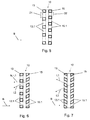
- FIG Fig. 6 Two examples of such protective elements 10 with differently oriented holes 13.1, 15.1 are shown in a schematic sectional view in FIG Fig. 6 and Fig. 7 shown.
- the holes 13.1 of the perforated plate 13 are oriented in the direction L1 which coincides with the plate normal N
- the holes 15.1 of the perforated plate 15 arranged parallel to the perforated plate 13 are arranged in a direction L2 which makes an angle of 25 ° with the plate normal N.
- the holes 13.1 are oriented in a direction L1 and the holes 15.1 are oriented in a direction L2, with the directions L1 and L2 enclosing an angle of 45 °.
- the protective element 10 according to the first embodiment in FIG Fig. 1 has perforated plates 13, 15, whose holes 13.1, 15.1 have the same cross-sectional area.
- the holes 13.1, 15.1 are all designed as cylindrical bores, so that the cross-sectional area of the holes 13.1, 15.1 is circular.
- the perforated plates 13, 15 of the protective element 10 may have holes with a different cross-sectional area.
- the holes 13.1 of the first armor plate 13 may have a circular cross-section and the holes 15.1 of the second armor plate 15 parallel to the first armor plate 13 may have an angular cross-sectional area.
- the holes 13.1, 15.1 of the two armor plates 13, 15 can have different diameters in order to optimize the protective effect of the perforated plates 13, 15 on different calibers of the impinging projectiles 1.
- the protective element 10 can have armor plates 13, 15 with holes of different sizes for protection against projectiles 1 with different caliber. It has proven to be advantageous in this case if the diameters of the holes 13.1, 15.1 of two perforated plates 13, 15 differ by at least 5%, preferably by at least 10%, particularly preferably by at least 50%, of the smaller diameter.
- FIG. 5 An example of such a protective element 10 with holes 13.1, 15.1 of different size is in the Fig. 5 shown.
- the holes 13.1 of the front perforated plate 13 have a diameter D1, which is selected to be larger than the diameter D2 of the holes 15.1 in the rear perforated plate 15.
- the diameter D1 can, for. B. 15 mm and the diameter D2 7 mm.
- the multi-layer protection element 10 comprises a plurality of perforated plates 13, 15, which have a different thickness from each other.
- the facing the threat side armor plate 13 is formed thicker than the threat side facing armor plate 15.
- Bullets 1, which impinge on the protective element 10 from the threat direction B, thus come first with the thicker armor plate 13 in contact.
- kinetic energy is withdrawn from the projectiles, they are divided into projectile fragments and possibly deflected.
- the projectile fragments then meet with far less kinetic energy on the viewed in threat direction B behind the first armor plate 13 second armor plate 15, which is formed thinner according to the lower energy of the projectile fragments.
- the weight of the protective element 10 can be reduced. It has proved to be advantageous here if the ratio of the thicknesses of the two perforated plates 13, 15 is at least 2, preferably at least 3, particularly preferably at least 5.
- the protective element 10 of the first exemplary embodiment can be arranged as an additional armor on a military vehicle 2. Due to the reduced weight of the protective element 10 while the mobility of the vehicle is hardly limited. Through the perforated plates 13, 15 of the protective element 10, the kinetic energy of ballistic projectiles 1 can be reduced such that they can be prevented from the basic armor 2.1 of the vehicle 2.
- the deflection effect of the perforated plates 13, 15 is particularly important, by which impinging projectiles 1 are deflected deflected by a direction of threat B oriented substantially perpendicular to the surface of the base armor 2.1 on a direction oriented obliquely to the surface of the base armor 2.1. Due to the deflection, the effect of the projectiles 1 on the basic armor 2.1 is weakened.
- a further reduction in the projectile effect can be achieved by separating the projectiles 1 or their fragments and impinging them on the base armor 2.1 distributed over a larger area.
- the distance between the protective element 10 and the base armor 2.1 is advantageously at least 1 cm, preferably at least 2 cm, more preferably at least 5 cm.
- the arrangement of the protective element 10 at a distance A in front of the base armor 2.1 can be made possible by spacers 3 having a depth corresponding to the distance A.
- the protective element 10 is arranged substantially perpendicular to a vehicle side of the vehicle 2.
- the holes 13.1, 15.1 of the protective element 10 extend starting from a side facing away from the vehicle - the threat side - in a direction from below obliquely upward.
- Such an ascending course of the holes 13.1, 15.1 has proven to be advantageous, since ballistic threats usually emanate from an essentially perpendicular to the vehicle side oriented threat direction B or from above obliquely downward in the direction of the vehicle 2.
- the holes 15.1 of the second perforated plate 15 can be arranged in the same way.
- Hole diameters and distances are chosen such that the diameter D of the holes 13.1 are greater than the distances E, F of the holes 13.1, so that a projectile 1 striking the perforated plate 13 is likely to come into contact with the perforated plate in the region of a hole 13.1.
- a ratio of the distance E, F to the diameter D of greater than 0.5, preferably greater than 0.55, particularly preferably greater than 0.6, is advantageous.
- a second embodiment of the protective element 10 is shown.
- the constituents of the protective element 10 of the second embodiment and their effects are similar to those of the first embodiment and are therefore denoted by the same reference numerals.
- the protective element 10 shown formed such that it can be used as a sole armor.
- the protective element 10 according to the second exemplary embodiment has, in addition to the layers of the protective element 10 according to the first exemplary embodiment, a solid base armor plate 17 and a second damping layer 16.
- a cover plate 11 is provided only on the threat side and has been dispensed with a rear, the threat of projectiles 1 side facing away from a cover plate.
- the basic armor plate 17 corresponds in its effect to the base armor 2.1 of the vehicle 2 in the first embodiment.
- the base armor plate 17 can be repelled on the perforated plates 13, 15 divided and / or deflected projectiles 1 or projectile fragments.
- the second damping layer 16 is arranged in the direction of threat B behind the second armor plate 15 and can therefore absorb kinetic energy from those projectiles which impinge on the second armor plate 15.
- the second cushioning layer is between the perforated armor plate 15 and the massive base armor plate 17 arranged and glued to both plates.
- a third embodiment of a protective element 10 in a sectional view shows Fig. 4 ,
- the components of the protective element 10 of the third embodiment and their effects are similar to those of the first two embodiments and are therefore denoted by the same reference numerals.
- the protective element 10 is also multi-layered and has a cover plate 11 formed as a 2 mm thick steel plate. Behind the cover plate 11, a first armor plate 13 with holes 13.1 is arranged, which is formed of armored steel and has a thickness of 15 mm. Glued to the armor plate 13 is a first damping layer 14, which consists of 20 mm thick aluminum foam. Behind the damping layer 14 is a glued with this second armor plate 15, which is designed as a 5 mm thick armor steel plate with holes 15.1. To the perforated plate 15 then a second cover plate 12 is provided, which is identical to the cover plate 11 and is connected via spacers 3 to the base armor 2.1 of the vehicle.
- a damping layer 16 formed of iron foam is further provided with a thickness of 20 mm.
- a 10 mm thick armor layer 2.2 Arranged on the vehicle in the area behind the base armor 2.1 is a 10 mm thick armor layer 2.2, which may be designed as a liner.
- the holes 13.1, 15.1 of the two armor plates 13, 15 are arranged offset to each other.
- the offset of the holes 13.1, 15.1 is selected such that a bullet through which arranged one behind the other Armor plates 13, 15 on a straight trajectory even with a projectile 1 arbitrarily small caliber is not possible.
- the exemplary embodiments of the protective element 10 described above have an armor plate 13, 15, which is designed as a perforated plate having a plurality of holes 13.1, 15.1, so that the weight of the protective element 10 is reduced. Due to the breaking, dividing and deflecting action of the holes 13.1, 15.1, a protective element 10 can be provided, which has improved protection against ballistic threats.
- the protective element 10 can therefore be used polyvalent against threats by ballistic projectiles 1 of different caliber.
- projectiles 1 which act by their kinetic energy (KE projectiles)
- KE projectiles kinetic energy
Abstract
Die Erfindung betrifft ein Schutzelement zum Schutz gegen ballistische Geschosse (1) mit einer Panzerungsplatte (13, 15), wobei die Panzerungsplatte (13, 15) als eine mehrere Löcher (13.1, 15.1) aufweisende Lochplatte ausgebildet ist sowie ein militärisches Fahrzeug mit einem derartigen Schutzelement (10).The invention relates to a protective element for protection against ballistic projectiles (1) with an armor plate (13, 15), wherein the armor plate (13, 15) as a plurality of holes (13.1, 15.1) having perforated plate is formed and a military vehicle with such Protective element (10).
Description
Die Erfindung betrifft ein Schutzelement zum Schutz gegen ballistische Geschosse mit einer Panzerungsplatte sowie ein militärisches Fahrzeug mit einem derartigen Schutzelement.The invention relates to a protective element for protection against ballistic projectiles with an armor plate and a military vehicle with such a protective element.
Schutzelemente werden im militärischen Anwendungsbereich an Fahrzeugen und anderen Einrichtungen, wie z. B. Gebäuden und Waffen, zur Abwehr von Gefahren unterschiedlicher Art eingesetzt. Zum Schutz gegen Geschosse mit ballistischer Wirkung, wie beispielsweise durch eine Treibladung beschleunigte Projektile oder projektilbildende Ladungen (explosively formed projectiles, EFP), können Schutzelemente mit einer Panzerungsplatte zum Einsatz kommen. Die Panzerungsplatte derartiger Schutzelemente ist üblicherweise massiv ausgeführt und weist eine erhöhte Beständigkeit gegenüber ballistischen Geschossen auf.Protective elements are used in military applications on vehicles and other facilities, such. As buildings and weapons used to ward off dangers of various kinds. For protection against bullet-impact projectiles, such as projectile-accelerated projectiles or projectile-forming charges (explosively formed projectiles, EFP), protective elements with an armor plate can be used. The armor plate of such protective elements is usually made solid and has an increased resistance to ballistic bullets.
Es sind verschiedene Verbundpanzerungen bekannt, die aus unterschiedlichen Materialien bestehen (z.B. Panzerstähle im Verbund mit Keramik- oder Keramikverbundvverkstoffen). Die Fertigung derartiger keramischer Panzerungsplatten gestaltet sich allerdings zeitaufwändig und ist mit vergleichsweise hohen Kosten verbunden. Weitaus geringere Herstellungskosten können erreicht werden, wenn die Panzerungsplatte aus Panzerstahl mit einer hohen Härte und Zähigkeit ausgebildet ist.Various composite armor made of different materials are known (e.g., armor steels in combination with ceramic or ceramic composite materials). However, the production of such ceramic armor plates is time-consuming and involves relatively high costs. Far lower manufacturing costs can be achieved if the armor plate is made of armored steel with a high hardness and toughness.
Um Schutz gegen Geschosse mit hoher kinetischer Energie zu ermöglichen, ist es erforderlich, die Panzerungsplatte entsprechend dick auszulegen, was mit einem erhöhten Gewicht des Schutzelements einhergeht. Im Hinblick auf die Verwendung derartiger Schutzelemente an militärischen Fahrzeugen bringt dies den Nachteil mit sich, dass die Beweglichkeit des Fahrzeugs durch das hohe Gewicht der Schutzelemente eingeschränkt wird.In order to provide protection against projectiles with high kinetic energy, it is necessary to make the armor plate correspondingly thick, which is associated with an increased weight of the protective element. With regard to the use of such protective elements on military vehicles, this entails the disadvantage that the mobility of the vehicle is limited by the high weight of the protective elements.
Vor diesem Hintergrund stellt sich die Erfindung die Aufgabe, das Gewicht des Schutzelements zu verringern, ohne dessen Schutzwirkung gegen ballistische Geschosse nachteilig zu beeinflussen.Against this background, the invention has the object to reduce the weight of the protective element, without adversely affecting its protective effect against ballistic projectiles.
Bei einem Schutzelement der eingangs genannten Art wird die Aufgabe dadurch gelöst, dass die Panzerungsplatte als eine mehrere Löcher aufweisende Lochplatte ausgebildet ist.In a protection element of the kind mentioned at the outset, the object is achieved in that the armor plate is formed as a plurality of holes having hole plate.
Im Bereich der Löcher ist das Material der Panzerungsplatte entfernt, so dass die durchlöcherte Panzerungsplatte ein im Vergleich zu einer massiven Panzerungsplatte verringertes Gewicht aufweist. Durch die Lochplatte kann somit das Gewicht des gesamten Schutzelements verringert werden.In the area of the holes, the material of the armor plate is removed so that the perforated armor plate has a reduced weight compared to a solid armor plate. The weight of the entire protective element can thus be reduced by the perforated plate.
Das erfindungsgemäße Schutzelement kann ein Schutzniveau aufweisen, welches mit dem Schutzniveau eines Schutzelements mit massiver Panzerungsplatte vergleichbar ist. Ein auf die Lochplatte auftreffendes Geschoss kann an den Löchern aufgebrochen und/oder in mehrere Teile zerteilt werden, so dass seine Durchschlagskraft vermindert werden kann. Teile des Geschosses können durch die Löcher der Lochplatte durchtreten und dabei das Geschoss aufreißen.The protective element according to the invention can have a level of protection that is comparable to the level of protection of a protective element with a solid armor plate. A projectile striking the perforated plate can be broken up at the holes and / or divided into several parts, so that its penetrating power can be reduced. Parts of the projectile can pass through the holes of the perforated plate and thereby tear the projectile.
Ferner können auftreffende Geschosse an den Kanten und/oder Innenwandungen der Löcher abgelenkt werden. Dieser Effekt der Löcher wirkt sich ebenfalls positiv auf die Schutzwirkung aus, da abgelenkte Geschosse eine verringerte kinetische Energie aufweisen können und somit leichter abgewehrt werden können.Furthermore, impacting projectiles can be deflected at the edges and / or inner walls of the holes. This effect of the holes also has a positive effect on the protective effect, since deflected projectiles can have a reduced kinetic energy and thus can be repelled more easily.
Somit kann durch die Erfindung ein Schutzelement mit verringertem Gewicht bereitgestellt werden, dessen Schutzwirkung gegen ballistische Geschosse durch die Löcher nicht nachteilig beeinflusst wird.Thus, the invention can provide a reduced weight protective element whose protective effect against ballistic projectiles through the holes is not adversely affected.
Die Löcher der Lochplatte können als die Panzerungsplatte vollständig durchdringende Durchgangslöcher ausgebildet sein. Es ist aber auch möglich, die Löcher als Sacklöcher auszubilden, welche die Panzerungsplatte nur teilweise durchdringen. Im Bereich der Sacklöcher kann das Material der Panzerungsplatte eine Dicke aufweisen, die höchstens 50 % der Dicke des die Löcher umgebenden Materials, bevorzugt 10 % der Dicke des die Löcher umgebenden Materials, besonders bevorzugt höchstens 5 % der Dicke des die Löcher umgebenden Materials entspricht.The holes of the perforated plate may be formed as the armor plate completely penetrating through holes. But it is also possible to form the holes as blind holes, which penetrate the armor plate only partially. In the area of the blind holes, the material of the armor plate may have a thickness which is at most 50% of the thickness of the material surrounding the holes, preferably 10% of the thickness of the material surrounding the holes, more preferably at most 5% corresponds to the thickness of the material surrounding the holes.
Gemäß einer vorteilhaften Ausgestaltung der Erfindung sind die Löcher in der Lochplatte rasterförmig verteilt angeordnet, so dass ein Bereich gebildet wird, in welchem auftreffende Geschosse aufgebrochen, zerteilt und/oder abgelenkt werden können. Ein Lochraster kann aus einer Vielzahl von Löchern gebildet werden, die hinsichtlich ihrer Größe gleich sind und/oder in gleichen orthogonalen Abständen zueinander angeordnet sind. Durch das Lochraster kann eine regelmäßig perforierte Oberfläche der Lochplatte ausgebildet werden, welche ein gleichmäßiges Schutzniveau aufweist. Das Lochraster kann sich über die gesamte der Bedrohung durch Geschosse zugewandte Oberfläche der Panzerungsplatte erstrecken, wodurch eine vollflächige Schutzwirkung gegen ballistische Geschosse ermöglich wird.According to an advantageous embodiment of the invention, the holes in the perforated plate are arranged distributed in a grid pattern, so that an area is formed in which impinging projectiles can be broken up, divided and / or deflected. A hole pattern may be formed from a plurality of holes that are equal in size and / or arranged at equal orthogonal distances from each other. Through the hole pattern, a regularly perforated surface of the perforated plate can be formed, which has a uniform level of protection. The breadboard can extend over the entire surface of the armor plate facing the bullet threat, providing full-scale ballistic bullet protection.
Im Hinblick auf die Schutzwirkung hat es sich ferner als vorteilhaft herausgestellt, wenn die Größe der Löcher kleiner als das Kaliber der auftreffenden Geschosse gewählt ist, so dass ein Geschoss ein Loch nicht durchdringen kann, ohne dabei aufgebrochen oder zerteilt zu werden. Ein wirksamer Schutz gegen Geschosse mit Kaliber 7,62 mm kann beispielsweise erreicht werden, wenn die Löcher einen Durchmesser von 7 mm aufweisen.With regard to the protective effect, it has also proven to be advantageous if the size of the holes is chosen to be smaller than the caliber of the impacting projectiles, so that a projectile can not penetrate a hole without being broken up or broken up. Effective protection against bullets of caliber 7.62 mm can be achieved, for example, if the holes have a diameter of 7 mm.
Die Löcher der Lochplatte können grundsätzlich eine beliebige Querschnittsfläche aufweisen. Für die Fertigung derartiger Schutzelemente hat es sich allerdings als vorteilhaft erwiesen, wenn die Löcher mit einer kreisförmigen Querschnittsfläche ausgebildet sind, so dass sie als zylindrische Bohrungen durch ein Bohrwerkzeug in die Panzerungsplatte eingebracht werden können.The holes of the perforated plate can basically have any cross-sectional area. For the production of such protective elements, however, it has proved to be advantageous if the holes are formed with a circular cross-sectional area, so that they can be introduced as cylindrical bores by a drilling tool in the armor plate.
Bevorzugt ist die Breite der Querschnittsfläche, insbesondere der Durchmesser, der Löcher größer als der Abstand zwischen den Löchern, so dass die auftreffenden Geschosse mit einer erhöhten Wahrscheinlichkeit im Bereich eines Lochs auf der Lochplatte auftreffen können. Das Verhältnis des Abstands zwischen den Löchern zu der Breite der Querschnittsfläche der Löcher kann im Bereich größer als 0,5, bevorzugt größer als 0,55, besonders bevorzugt größer als 0,6, liegen. Geschosse mit dem Kaliber 7,62 mm können z. B. wirksam abgewehrt werden, wenn die Löcher einen Durchmesser von 7 mm aufweisen und 4 mm von einander beabstandet sind.Preferably, the width of the cross-sectional area, in particular the diameter, of the holes is greater than the distance between the holes, so that the impacting projectiles can hit with an increased probability in the region of a hole on the perforated plate. The ratio of the distance between the holes to the width of the cross-sectional area of the holes can be in the range greater than 0.5, preferably greater than 0.55, particularly preferably greater than 0.6. Bullets with the caliber 7.62 mm can z. B. are effectively fended off when the holes have a diameter of 7 mm and are 4 mm apart.
Um die Schutzwirkung zu erhöhen, kann das Schutzelement mehrere, geschichtet angeordnete Lochplatten aufweisen, so dass solche Geschosse die in der ersten Lochplatte nicht vollständig abgebremst werden können, auf eine zweite, hinter der ersten Lochplatte angeordnete Lochplatte auftreffen können. Somit kann ein in das Schutzelement eindringendes Geschoss an den geschichteten Lochplatten mehrfach zerteilt und/oder abgelenkt werden. Die Lochplatten können in mehreren parallelen Lagen angeordnet sein oder schräg zu einander orientiert sein. Zwischen den einzelnen Lochplatten kann ein Freiraum vorgesehen sein, welchen Geschossfragmente ungehindert durchdringen können. Alternativ können die Lochplatten direkt oder über eine Zwischenschicht miteinander verbunden sein. Durch den Schichtaufbau kann das Schutzelement polyvalent gegen unterschiedliche Bedrohungen schützen.In order to increase the protective effect, the protective element can have a plurality of perforated plates arranged in a layered manner, so that such projectiles which can not be completely decelerated in the first perforated plate can impinge on a second perforated plate arranged behind the first perforated plate. Thus, a projectile penetrating into the protective element can be repeatedly divided and / or deflected at the layered perforated plates. The perforated plates may be arranged in several parallel layers or oriented obliquely to each other. Between the individual perforated plates, a free space can be provided, which projectile fragments can penetrate unhindered. Alternatively, the perforated plates can be connected to each other directly or via an intermediate layer. Due to the layer structure, the protective element can protect polyvalent against different threats.
Bei einem Schutzelement mit mehreren Lochplatten ist es besonders bevorzugt, wenn die Löcher zweier Lochplatten zueinander versetzt angeordnet sind. Durch den Versatz der Löcher kann das Schutzelement nicht auf einer im Wesentlichen geraden Trajektorie - also ohne eine mit einem Verlust an kinetischer Energie verbundenen Ablenkung - durchdrungen werden. Ein Durchschuss eines Geschosses mit geringem Kaliber durch die Löcher mehrerer Lochplatten kann somit verhindert werden.In a protective element with a plurality of perforated plates, it is particularly preferred if the holes of two perforated plates are arranged offset from one another. Due to the offset of the holes, the protective element can not be penetrated on a substantially straight trajectory, that is to say without a deflection associated with a loss of kinetic energy. A bullet a bullet with low caliber through the holes of several perforated plates can thus be prevented.
Um die Durchschlagskraft ballistischer Geschosse weiter zu verringern, ist es ferner vorteilhaft, wenn das Schutzelement eine Dämpfungsschicht zur Absorption von kinetischer Energie auftreffender Geschosse aufweist.In order to further reduce the impact force of ballistic projectiles, it is also advantageous if the protective element has a damping layer for absorbing kinetic energy of impacting projectiles.
Zur Abwehr projektilbildender Ladungen hat es sich besonders bewährt, wenn die Dämpfungsschicht auf einer der Bedrohung durch auftreffende Geschosse abgewandten Seite der Lochplatte angeordnet ist. Das Projektil der projektilbildenden Ladung kann aufgrund der elastischen Wirkung der Dämpfungsschicht an der Oberfläche der im Vergleich zu der Dämpfungsschicht harten Lochplatte kurzzeitig aufgehalten werden. Dabei kann sich die Spitze des Projektils verformen und das Material des Projektils lateral entlang der Oberfläche der Lochplatte entlang fließen, so dass das Projektil aufgeweitet wird. Besonders bevorzugt ist die Dämpfungsschicht zwischen zwei Lochplatten angeordnet, so dass die Projektile in dem Schichtaufbau des Schutzelements mehrfach aufgeweitet, zerteilt und/oder abgelenkt werden können. Bei einem Schutzelement mit mehreren Lochplatten kann ein Dämpfungselement hinter mehreren Lochplatten vorgesehen sein.To defend projectile-forming charges, it has proven particularly useful if the damping layer is arranged on a side facing away from the threat of impinging projectiles of the perforated plate. Due to the elastic effect of the damping layer on the surface of the perforated plate, which is hard in comparison to the damping layer, the projectile of the projectile-forming charge can be stopped for a short time. In this case, the tip of the projectile can deform and the material of the projectile laterally along the surface of the perforated plate flow along, so that the projectile is widened. Particularly preferably, the damping layer is arranged between two perforated plates, so that the projectiles in the layer structure of the protective element can be repeatedly expanded, divided and / or deflected. In a protective element having a plurality of perforated plates, a damping element may be provided behind a plurality of perforated plates.
Bevorzugt weist das Schutzelement zudem eine insbesondere massive Grundpanzerungsplatte auf, die auf einer der Bedrohung durch auftreffende Geschosse abgewandten Seite der Lochplatte angeordnet ist. Die Geschosse können beim Durchtritt durch die Lochplatte abgelenkt und von der Grundpanzerungsplatte abgefangen werden, so dass ein erhöhter Schutz erreicht werden kann.Preferably, the protective element also has a particular massive base armor plate, which is arranged on a side facing away from the threat of impinging projectiles of the perforated plate. The projectiles can be deflected when passing through the perforated plate and intercepted by the base armor plate, so that an increased protection can be achieved.
Im Hinblick auf die Montage mehrlagiger Schutzelemente hat es sich ferner als vorteilhaft herausgestellt, wenn die Lochplatte mit einer Dämpfungsschicht und/oder einer zweiten Lochplatte fest verbunden ist. Die Verbindung kann als Verklebung ausgebildet sein, wodurch eine vereinfachte Fertigung des Schutzelements ermöglicht wird. Alternativ kann die Verbindung über Verschweißen oder über Vulkanisierung gebildet werden.With regard to the assembly of multi-layer protective elements, it has also been found to be advantageous if the perforated plate is firmly connected to a damping layer and / or a second perforated plate. The connection may be formed as a bond, whereby a simplified production of the protective element is made possible. Alternatively, the connection may be formed by welding or vulcanization.
Eine weitere Erleichterung für die Handhabung des Schutzelements kann erreicht werden, wenn eine Deckplatte zur Abdeckung des Schutzelements vorgesehen ist. Die Deckplatte kann das Schutzelement nach Art eines Gehäuses umschließen, wodurch das Schutzelement kompakt transportiert und als Zusatzpanzerung verwendet werden kann. Bevorzugt ist die Deckplatte lackierbar ausgebildet, so dass das Erscheinungsbild des Schutzelements an das des militärischen Fahrzeugs oder der militärischen Einrichtung angepasst werden kann. Ferner kann eine rutschfeste Beschichtung der Deckplatte vorgesehen sein.A further relief for the handling of the protective element can be achieved if a cover plate is provided to cover the protective element. The cover plate can enclose the protective element in the manner of a housing, whereby the protective element can be compactly transported and used as additional armor. Preferably, the cover plate is designed paintable, so that the appearance of the protective element can be adapted to that of the military vehicle or the military device. Furthermore, a non-slip coating of the cover plate may be provided.
Die Löcher der Lochplatte können in Richtung der Plattennormalen der Lochplatte verlaufen. Gemäß einer vorteilhaften Ausgestaltung verlaufen die Löcher in einer Richtung schräg zur Plattennormalen. Durch die schräg in das Plattenmaterial eingebrachten Löcher kann das Gewicht der Panzerungsplatte weiter verringert werden, da im Vergleich zu solchen Löchern, die in Richtung der Plattennormalen verlaufen, mehr Material der Panzerungsplatte entfernt wird. Die Richtung der Löcher kann mit der Plattennormalen einen Winkel einschließen, der kleiner als 90° beträgt. Durch diesen Lochwinkel kann die Ablenkung und Fragmentierung der auf die Lochplatte auftreffenden Geschosse beeinflusst werden.The holes of the perforated plate can run in the direction of the plate normal of the perforated plate. According to an advantageous embodiment, the holes extend in a direction oblique to the plate normal. By the obliquely introduced into the plate material holes, the weight of the armor plate can be further reduced, as compared to such holes, which run in the direction of the plate normal, more material of the armor plate is removed. The direction of the holes may include an angle that is less than 90 ° with the plate normal. This hole angle can influence the deflection and fragmentation of the projectiles impacting the perforated plate.
In diesem Zusammenhang hat es sich als besonders vorteilhaft erwiesen, wenn die Richtung der Löcher und die Plattennormale einen Winkel von mindestens 5°, bevorzugt von mindestens 10°, besonders bevorzugt von mindestens 20°, einschließen, so dass auf die Lochplatte auftreffende Geschosse stark abgelenkt werden können.In this context, it has proved to be particularly advantageous if the direction of the holes and the plate normal include an angle of at least 5 °, preferably of at least 10 °, more preferably of at least 20 °, so that strongly deflects impacting the perforated plate projectiles can be.
Schräg in die Lochplatte eingebrachte Löcher können auch bei einem mehrlagigen Schutzelement Anwendung finden. Bevorzugt weist das Schutzelement mehrere Lochplatten auf, deren Löcher in unterschiedlichen Richtungen verlaufen. Auf diese Weise können verschiedene Lochplatten des Schutzelements eine unterschiedliche Wirkung auf auftreffende Geschosse ausüben. Ferner kann die Gefahr von Durchschüssen verringert werden. Die Löcher einer Lochplatte können hierbei in derselben Richtung ausgerichtet sein. Löcher verschiedener parallel angeordneter Platten können jeweils einen unterschiedlichen Winkel mit der Oberfläche einschließen. Ferner ist es möglich, die Löcher einer Platte in Richtung der Plattennormalen und die Löcher einer weiteren Platte schräg zur Plattennormalen anzuordnen.Slots introduced obliquely into the perforated plate can also be used with a multilayer protective element. Preferably, the protective element has a plurality of perforated plates whose holes extend in different directions. In this way, different perforated plates of the protective element can exert a different effect on impinging projectiles. Furthermore, the risk of bullets can be reduced. The holes of a perforated plate can hereby be aligned in the same direction. Holes of different parallel plates may each subtend a different angle with the surface. Further, it is possible to arrange the holes of one plate in the direction of the plate normal and the holes of another plate obliquely to the plate normal.
In diesem Zusammenhang hat es sich als besonders bevorzugt erwiesen, wenn die Richtungen der Löcher zweier Lochplatten einen Winkel von mindestens 5°, bevorzugt von mindestens 10°, besonders bevorzugt von mindestens 20° einschließen.In this context, it has proved to be particularly preferred if the directions of the holes of two perforated plates form an angle of at least 5 °, preferably of at least 10 °, particularly preferably of at least 20 °.
Gemäß einer weiteren vorteilhaften Ausgestaltung weist das Schutzelement mehrere Lochplatten auf, deren Löcher eine unterschiedliche Querschnittsfläche aufweisen. Über die Querschnittsfläche kann die Schutzwirkung der jeweiligen Lochplatte an unterschiedliche Geschosse angepasst werden. Hierbei ist es möglich, die Löcher einer Lochplatte jeweils mit gleicher Querschnittsfläche auszubilden. Die Querschnittsfläche kann rund, polygonal, insbesondere drei-, vier-, fünf-, sechseckig, oder mit einem beliebigen Grundriss ausgebildet sein. Besonders bevorzugt weisen hintereinander angeordnete parallele Lochplatten Löcher unterschiedlicher Größe auf, so dass das Schutzelement auf die Abwehr von unterschiedlichen Geschosstypen ausgelegt werden kann.According to a further advantageous embodiment, the protective element has a plurality of perforated plates whose holes have a different cross-sectional area. About the cross-sectional area, the protective effect of the respective perforated plate can be adapted to different floors. In this case, it is possible to form the holes of a perforated plate in each case with the same cross-sectional area. The cross-sectional area can be round, polygonal, in particular three, four, five, hexagonal, or be formed with any floor plan. Particularly preferably, successively arranged parallel perforated plates on holes of different sizes, so that the protective element can be designed to defend against different types of bullets.
Im Hinblick auf solche Löcher, die als zylindrische Bohrungen in der Lochplatte ausgebildet sind, hat es sich als vorteilhaft erwiesen, wenn die Löcher zweier Lochplatten unterschiedliche Durchmesser aufweisen. Die Löcher einer Lochplatte können dabei denselben Durchmesser aufweisen. Über den Durchmesser kann die Schutzwirkung an das Kaliber der Geschosse angepasst werden.With regard to such holes, which are formed as cylindrical holes in the perforated plate, it has proven to be advantageous if the holes of two perforated plates have different diameters. The holes of a perforated plate can have the same diameter. The protective effect can be adapted to the caliber of the projectiles via the diameter.
Hierbei können sich die Durchmesser um mindestens 5 %, bevorzugt mindestens 25 %, besonders bevorzugt mindestens 50 %, des kleineren Durchmessers unterscheiden.In this case, the diameters may differ by at least 5%, preferably at least 25%, particularly preferably at least 50%, of the smaller diameter.
Eine weitere bevorzugte Ausgestaltung des Schutzelements weist mehrere Lochplatten mit unterschiedlicher Dicke auf. Über die Dicke der Lochplatten kann die Beständigkeit der Lochplatte gegenüber auftreffenden Geschossen beeinflusst werden. Um die Schutzwirkung der Lochplatte zu erhöhen, kann die Dicke der Lochplatte erhöht werden, wobei allerdings auch das Gewicht der Lochplatte erhöht wird.A further preferred embodiment of the protective element has a plurality of perforated plates with different thickness. The thickness of the perforated plates can influence the resistance of the perforated plate to impacting projectiles. In order to increase the protective effect of the perforated plate, the thickness of the perforated plate can be increased, but also the weight of the perforated plate is increased.
Ein Schutzelement mit hoher Schutzwirkung und geringem Gewicht kann bereitgestellt werden, wenn eine der Bedrohung durch auftreffende Geschosse zugewandte Lochplatte dicker ausgebildet ist, als eine der Bedrohung abgewandte Lochplatte. Auftreffende Geschosse können zunächst an der dickeren Lochplatte aufgebrochen, zerteilt und ggf. abgelenkt werden, bevor sie auf die zweite Lochplatte mit geringerer Schutzwirkung treffen. Bevorzugt weist die dickere Platte auch größere Löcher als die dünnere Platte auf.A protective element with a high protective effect and low weight can be provided if a perforated plate facing the threat of impinging projectiles is made thicker than a perforated plate facing away from the threat. Impacting projectiles can first be broken up at the thicker perforated plate, split and, if necessary, deflected before they hit the second perforated plate with less protective effect. Preferably, the thicker plate also has larger holes than the thinner plate.
Als vorteilhaft hat es sich hierbei herausgestellt, wenn das Verhältnis der Dicken zweier Lochplatten mindestens zwei, bevorzugt mindestens drei, besonders bevorzugt mindestens fünf beträgt.It has proven to be advantageous in this case if the ratio of the thicknesses of two perforated plates is at least two, preferably at least three, particularly preferably at least five.
Gemäß einer weiteren vorteilhaften Ausgestaltung der Erfindung sind die Löcher mit einem von dem Material der Lochplatte abweichenden Füllmaterial gefüllt. Durch das Füllmaterial können die Lochplatten z. B. gegen das Eindringen von Staub oder gasförmigen Verschmutzungen geschützt werden.According to a further advantageous embodiment of the invention, the holes are filled with a deviating from the material of the perforated plate filling material. Due to the filling material, the perforated plates z. B. against the ingress of dust or gaseous pollutions are protected.
Im Hinblick auf das Füllmaterial hat es sich als besonders vorteilhaft erwiesen, wenn dieses eine geringere, insbesondere wesentlich geringere, Dichte als das Material der Lochplatte aufweist. Das Verhältnis der unterschiedlichen Dichten kann mehr als 1:3, insbesondere mehr als 1:6, betragen. Bevorzugt liegt es im Bereich von 1:6 bis 1:10. Durch das Füllmaterial kann die Masse der Lochplatte nur geringfügig vergrößert werden. Gleichzeitig kann erreicht werden, dass die Lochplatte eine aufbrechende, zerteilende und/oder ablenkende Wirkung auf auftreffende Geschosse ausübt. Als Füllmaterial kann insbesondere ein Kleber verwendet werden, der auch zum Verkleben der Lochplatte mit angrenzenden Schichten Verwendung finden kann. Das Füllmaterial, insbesondere ein Kleber, kann in die Löcher in festem Zustand eingebracht oder in flüssigem Zustand eingebracht und anschließend ausgehärtet werden.With regard to the filling material, it has proved to be particularly advantageous if this has a lower, in particular substantially lower, density than the material of the perforated plate. The ratio of the different densities can be more than 1: 3, in particular more than 1: 6. It is preferably in the range from 1: 6 to 1:10. Due to the filling material, the mass of the perforated plate can only be increased slightly. At the same time it can be achieved that the perforated plate exerts an exploding, dividing and / or distracting effect on impinging projectiles. In particular, an adhesive which can also be used for bonding the perforated plate to adjacent layers can be used as the filling material. The filling material, in particular an adhesive, can be introduced into the holes in the solid state or introduced in the liquid state and then cured.
Ein weiterer Gegenstand der Erfindung ist ein militärisches Fahrzeug mit einem Schutzelement der eingangs genannten Art. Bei einem derartigen Fahrzeug tragen die bereits im Zusammenhang mit dem erfindungsgemäßen Schutzelement beschriebenen Merkmale zur Lösung der Aufgabe bei.Another object of the invention is a military vehicle with a protective element of the type mentioned. In such a vehicle, the features already described in connection with the protective element according to the invention contribute to the solution of the problem.
Das Schutzelement kann nach Art einer Nachrüstlösung als Zusatzpanzerung auf einer Grundpanzerung des militärischen Fahrzeugs angeordnet sein. Hierbei ist es bevorzugt, wenn das Schutzelement in einem Abstand vor der Grundpanzerung des Fahrzeugs angeordnet ist. Auf das Schutzelement auftreffende Geschosse können an der Lochplatte abgelenkt werden und in einem schrägen Winkel auf die beabstandete Grundpanzerung des Fahrzeugs auftreffen. Durch derartig abgelenkte Geschosse und/oder Geschossfragmente kann eine geringere Bedrohung für die Grundpanzerung ausgehen, als dies bei senkrecht auf die Grundpanzerung auftreffenden Geschossen und/oder Geschossfragmenten der Fall wäre.The protective element can be arranged in the manner of a retrofit solution as additional armor on a base armor of the military vehicle. In this case, it is preferred if the protective element is arranged at a distance in front of the base armor of the vehicle. Projectiles impinging on the protective element can be deflected at the perforated plate and impinge on the spaced basic armor of the vehicle at an oblique angle. Such deflected projectiles and / or projectile fragments may pose a lesser threat to the base armor than would be the case with projectiles and / or projectile fragments impinging vertically on the base armor.
Als besonders bevorzugt hat es sich hierbei herausgestellt, wenn der Abstand des Schutzelements zu der Grundpanzerung mindestens 1 cm, bevorzugt mindestens 2 cm, besonders bevorzugt mindestens 5 cm, beträgt. Zur Halterung des Schutzelements können Abstandshalter zwischen dem Schutzelement und der Grundpanzerung angeordnet sein.In this case, it has proven to be particularly preferable if the distance between the protective element and the base armor is at least 1 cm, preferably at least 2 cm, particularly preferably at least 5 cm. For holding the protective element spacers may be arranged between the protective element and the base armor.
Im Hinblick auf Bedrohungen durch ballistische Geschosse hat es sich ferner als vorteilhaft erwiesen, wenn das Schutzelement an einer Fahrzeugseite angeordnet ist, wobei die Löcher ausgehend von einer dem Fahrzeug abgewandten Seite in einer Richtung von unten schräg nach oben verlaufen. Da ein Beschuss mit ballistischen Geschossen aus einer Richtung schräg von unten unwahrscheinlich ist, kann durch eine derartige Anordnung der Löcher die Gefahr eines direkten Durchschusses durch eine Lochplatte des Schutzelements stark verringert werden.With regard to threats from ballistic missiles, it has also proven to be advantageous if the protective element is arranged on a vehicle side, wherein the holes, starting from a side facing away from the vehicle in a direction from below obliquely upward. Since it is unlikely that ballistic missiles from a direction obliquely from below, the danger of a direct penetration through a perforated plate of the protective element can be greatly reduced by such an arrangement of the holes.
Im Zusammenhang mit dem erfindungsgemäßen Fahrzeug können ferner auch die im Zusammenhang mit dem erfindungsgemäßen Schutzelement beschriebenen vorteilhaften Ausgestaltungen zur Anwendung kommen.In connection with the vehicle according to the invention, furthermore, the advantageous embodiments described in connection with the protective element according to the invention can also be used.
Weitere Vorteile und Ausgestaltungen der Erfindung sollen im Folgenden anhand der in den Figuren dargestellten Ausführungsbeispiele erläutert werden. Hierin zeigt:
- Fig. 1
- eine erste Ausgestaltung eines Schutzelements als Zusatzpanzerung in einer Schnittdarstellung;
- Fig. 2
- eine zweite Ausgestaltung eines Schutzelements in einer Schnittdarstellung;
- Fig. 3
- eine Ansicht einer Lochplatte von einer Bedrohungsseite;
- Fig. 4
- eine dritte Ausgestaltung eines Schutzelements in einer Schnittdarstellung;
- Fig. 5
- eine schematische Schnittdarstellung eines Schutzelements mit Löchern unterschiedlicher Größe; und
- Fig. 6-7
- schematische Schnittdarstellungen von Schutzelementen mit unterschiedlich orientierten Löchern.
- Fig. 1
- a first embodiment of a protective element as additional armor in a sectional view;
- Fig. 2
- a second embodiment of a protective element in a sectional view;
- Fig. 3
- a view of a perforated plate from a threat side;
- Fig. 4
- a third embodiment of a protective element in a sectional view;
- Fig. 5
- a schematic sectional view of a protective element with holes of different sizes; and
- Fig. 6-7
- schematic sectional views of protective elements with differently oriented holes.
Die
Die Löcher der ebenen Lochplatten 13, 15 sind als Durchgangslöcher ausgebildet. Neben der Verringerung des Gewichts der Schutzplatten 13, 15 kann durch die Löcher 13.1, 15.1 die Schutzwirkung im Vergleich zu einer massiven Panzerungsplatte 13, 15 gegen ballistische Geschosse 1 erhöht werden. Denn ein auf eine Lochplatte 13, 15 auftreffendes Geschoss kann an den Löchern 13.1, 15.1 aufgebrochen und/oder fragmentiert werden. Hierdurch kann die kinetische Energie des Geschosses 1 verringert und somit seine Durchschlagskraft vermindert werden. Es ist möglich, dass Teile des Geschosses 1 durch die Löcher 13.1 der vorderen Panzerungsplatte 13 hindurch gelangen können. In der Regel werden diese Geschossfragmente jedoch bereits an den Löchern 13.1 der vorderen Lochplatte 13 abgelenkt und treffen daher nicht in senkrechtem Winkel auf die dahinter liegenden Schichten 14, 15, 12, 2.1. Daher können die hinteren Schichten 14, 15, 12, 2.1 ein geringeres Schutzniveau aufweisen. Die Schutzwirkung der Lochplatte 13, 15 ist besonders stark ausgeprägt, wenn die Größer der Löcher 13.1, 15.1 an das Kaliber der auftreffenden Geschosse 1 angepasst ist. Hierzu kann die Größe der Löcher 13.1, 15.1 kleiner als das Kaliber der auftreffenden Geschosse 1 gewählt werden, so dass ein Geschoss 1 ein Loch 13.1, 15.1 nicht durchdringen kann, ohne dabei aufgebrochen oder zerteilt zu werdenThe holes of the flat
Das Schutzelement 10 ist mehrlagig ausgebildet. Es weist zwei Lochplatten 13, 15 aus Panzerstahl sowie eine zwischen den Lochplatten 13, 15 angeordnete Dämpfungsschicht 14 aus einem Metallschaum auf. Bevorzugt wird als Metallschaum ein Eisenschaum gewählt. Durch die Dämpfungsschicht 14 kann die Energie der auf der vorderen Lochplatte 13 auftreffenden Geschosse 1 absorbiert werden. Hierzu ist die Dämpfungsschicht 14 auf der der Bedrohung durch Geschosse 1 abgewandten Seite der Lochplatte 13 angeordnet, so dass ein Geschoss 1 zunächst auf der im Vergleich zu der Dämpfungsschicht 14 harten Lochplatte 13 auftrifft. Die Wucht des auftreffenden Geschosses kann durch die hinter der Lochplatte 13 angeordneten Dämpfungsschicht 14 elastisch aufgefangen werden. Bei Geschossen 1, welche als projektilbildende Ladungen ausgebildet sind, kann hierdurch ein so genannter "Dwell-Effekt" ausgelöst werden. Hierbei kann das Material des Geschosses 1 kurzzeitig an der Oberfläche der Lochplatte 13 verweilen und sich in lateraler Richtung entlang der Oberfläche verteilen, so dass das Geschoss 1 aufgeweitet wird.The
Um die Panzerungsplatten 13, 15 sowie die Dämpfungsschicht 14 gegen Umwelteinflüsse zu schützen, weist das Schutzelement 10 ein Gehäuse auf. In dem Ausführungsbeispiel gemäß
Neben den vorstehend genannten Materialien können für die Schichten 11, 12, 13, 14, 15 des Schutzelements 10 alternativ Titanlegierungen, Wolframsintermetallen Schäume und glasfaserverstärkte Kunststoffschichten Verwendung finden.In addition to the materials mentioned above, it is alternatively possible for the
Die Deckplatte 11, die perforierte Panzerungsplatte 13, die Dämpfungsschicht 14, die perforierte Panzerungsplatte 15 sowie die Deckplatte 12 sind jeweils mit der angrenzenden Schicht über einen Kleber fest verbunden. Die Löcher 13.1 und 15.1 der beiden Panzerungsplatten 13, 15 sind dabei mit dem Kleber aufgefüllt. Der Kleber bildet ein Füllmaterial, welches eine wesentlich geringere Dichte als das Material der Panzerungsplatten 13, 15 aufweist und daher die aufbrechende, zerteilende und ggf. ablenkende Wirkung auf die auftreffenden Geschosse 1 nicht beeinträchtigt.The
Wie der Darstellung in der
Bei dem Ausführungsbeispiel verlaufen die Löcher 13.1, 15.1 der beiden Lochplatten 13, 15 in derselben Richtung L. Abweichend von dem Ausführungsbeispiel können die Löcher 13.1, 15.1 verschiedener Lochplatten 13, 15 unterschiedliche Lochrichtungen aufweisen. Auf diese Weise kann verhindert werden, dass ein Geschoss 1 mit im Vergleich zu der Größe der Löcher 13.1, 15.1 kleinem Kaliber das Schutzelement 10 auf einer geraden Trajektorie durchdringen kann. Beispielsweise kann die Richtung der Löcher 13.1 in der ersten Panzerungsplatte 13 mit der Richtung der Löcher 15.1 in der zweiten zur ersten Panzerungsplatte 13 parallel angeordneten Panzerungsplatte 15 einen Winkel einschließen der größer als 0° beträgt. Vorteilhafterweise beträgt der Winkel zwischen den Richtungen der Löcher zweier unterschiedlicher Panzerungsplatten 13, 15 mindestens 5°, bevorzugt mindestens 10°, besonders bevorzugt mindestens 20°.In the exemplary embodiment, the holes 13.1, 15.1 of the two
Zwei Beispiele derartiger Schutzelemente 10 mit unterschiedlich orientierten Löchern 13.1, 15.1 sind in schematischer Schnittdarstellung in der
Das Schutzelement 10 gemäß dem ersten Ausführungsbeispiel in
Ein Beispiel eines derartigen Schutzelements 10 mit Löchern 13.1, 15.1 unterschiedlicher Größe ist in der
Bei Betrachtung der Darstellung in
Das Schutzelement 10 des ersten Ausführungsbeispiels kann als Zusatzpanzerung an einem militärischen Fahrzeug 2 angeordnet werden. Durch das verringerte Gewicht des Schutzelements 10 wird dabei die Beweglichkeit des Fahrzeugs kaum eingeschränkt. Durch die Lochplatten 13, 15 des Schutzelements 10 kann die kinetische Energie ballistischer Geschosse 1 derart verringert werden, dass sie von der Grundpanzerung 2.1 des Fahrzeugs 2 abgehalten werden können. In diesem Zusammenhang ist insbesondere der Ablenkungseffekt der Lochplatten 13, 15 von Bedeutung, durch welchen auftreffende Geschosse 1 von einer im Wesentlichen senkrecht zu der Oberfläche der Grundpanzerung 2.1 orientierten Bedrohungsrichtung B abgelenkt auf eine schräg zu der Oberfläche der Grundpanzerung 2.1 orientierten Richtung abgelenkt werden. Durch die Ablenkung wird die Wirkung der Geschosse 1 auf die Grundpanzerung 2.1 abgeschwächt.The
Eine weitere Reduktion der Geschosswirkung kann dadurch erreicht werden, dass die Geschosse 1 bzw. deren Fragmente separiert werden und über eine größere Fläche verteilt auf der Grundpanzerung 2.1 auftreffen. Auf diesen Separationseffekt wirkt es sich vorteilhaft aus, wenn der Abstand zwischen einer Lochplatte 13, 15 des Schutzelements 10 und der massiven Grundpanzerung 2.1 möglichst groß gewählt wird. Hierbei beträgt der Abstand zwischen dem Schutzelement 10 und der Grundpanzerung 2.1 vorteilhafterweise mindestens 1 cm, bevorzugt mindestens 2 cm, besonders bevorzugt mindestens 5 cm. Die Anordnung des Schutzelements 10 in einem Abstand A vor der Grundpanzerung 2.1 kann durch Abstandshalter 3 mit einer dem Abstand A entsprechenden Tiefe ermöglicht werden.A further reduction in the projectile effect can be achieved by separating the
Gemäß der Darstellung in
Anhand der Darstellung in der
Die Löcher 13.1 weisen einen identischen Durchmesser D von 7 mm auf und bilden ein gleichmäßiges Lochraster der Lochplatte 13. Der Abstand der Löcher ist gleichmäßig gewählt. In einer Richtung X entlang der Oberfläche der Lochplatte 13 beträgt der Abstand E der Löcher 4 mm. In einer zu der Richtung X orthogonalen Richtung Y sind die Löcher ebenfalls mit einem Abstand F = 4 mm beabstandet. Alternativ können die Abstände der Löcher E, F unterschiedlich gewählt werden.The holes 13.1 have an identical diameter D of 7 mm and form a uniform hole pattern of the
Lochdurchmesser und -abstände sind derart gewählt, dass der Durchmesser D der Löcher 13.1 größer als die Abstände E, F der Löcher 13.1 sind, so dass ein auf die Lochplatte 13 auftreffendes Geschoss 1 mit hoher Wahrscheinlichkeit im Bereich eines Lochs 13.1 mit der Lochplatte in Kontakt gerät. Vorteilhaft ist ein Verhältnis des Abstands E, F zu dem Durchmesser D von größer als 0,5, bevorzugt größer als 0,55, besonders bevorzugt von größer als 0,6.Hole diameters and distances are chosen such that the diameter D of the holes 13.1 are greater than the distances E, F of the holes 13.1, so that a projectile 1 striking the
In der
Im Gegensatz zu dem ersten Ausführungsbeispiel ist das in der
Die Grundpanzerungsplatte 17 entspricht in ihrer Wirkung der Grundpanzerung 2.1 des Fahrzeugs 2 in dem ersten Ausführungsbeispiel. Durch die Grundpanzerungsplatte 17 können an den Lochplatten 13, 15 zerteilte und/oder abgelenkte Geschosse 1 oder Geschossfragmente abgewehrt werden.The
Die zweite Dämpfungsschicht 16 ist in Bedrohungsrichtung B hinter der zweiten Panzerungsplatte 15 angeordnet und kann daher kinetische Energie von solchen Geschossen aufnehmen, welche auf der zweiten Panzerungsplatte 15 auftreffen. Die zweite Dämpfungsschicht ist zwischen der perforierten Panzerungsplatte 15 und der massiven Grundpanzerungsplatte 17 angeordnet und mit beiden Platten verklebt.The second damping
Ein drittes Ausführungsbeispiel eines Schutzelements 10 in einer Schnittdarstellung zeigt
Das Schutzelement 10 ist ebenfalls mehrlagig ausgebildet und weist eine als 2 mm dicke Stahlplatte ausgebildete Deckplatte 11 auf. Hinter der Deckplatte 11 ist eine erste Panzerungsplatte 13 mit Löchern 13.1 angeordnet, welche aus Panzerstahl gebildet ist und eine Dicke von 15 mm aufweist. Mit der Panzerungsplatte 13 verklebt ist eine erste Dämpfungsschicht 14, die aus 20 mm dickem Aluminiumschaum besteht. Hinter der Dämpfungsschicht 14 befindet sich eine mit dieser verklebte, zweite Panzerungsplatte 15, die als 5 mm dicke Panzerstahlplatte mit Löchern 15.1 ausgebildet ist. An die Lochplatte 15 anschließend ist eine zweite Deckplatte 12 vorgesehen, welche identisch zu der Deckplatte 11 ausgebildet ist und über Abstandshalter 3 mit der Grundpanzerung 2.1 des Fahrzeugs verbunden ist. Im Bereich zwischen der Deckplatte 12 und der Grundpanzerung 2.1 ist ferner eine aus Eisenschaum gebildete Dämpfungsschicht 16 mit einer Dicke von 20 mm vorgesehen. An dem Fahrzeug ist im Bereich hinter der Grundpanzerung 2.1 eine 10 mm dicke Panzerungsschicht 2.2 aus Aramid angeordnet, die als Liner ausgebildet sein kann.The
Wie der
Die vorstehend beschriebenen Ausführungsbeispiele des Schutzelements 10 weisen eine Panzerungsplatte 13, 15 auf, welche als eine mehrere Löcher 13.1, 15.1 aufweisende Lochplatte ausgebildet ist, so dass das Gewicht des Schutzelements 10 verringert wird. Aufgrund der aufbrechenden, zerteilenden und ablenkenden Wirkung der Löcher 13.1, 15.1 kann ein Schutzelement 10 bereitgestellt werden, welches verbesserte Schutzeigenschaften gegen ballistische Bedrohungen aufweist.The exemplary embodiments of the
Durch den mehrschichtigen Aufbau des Schutzelements 10 kann ein Synergieeffekt hervorgerufen werden. Einige Schichten, wie z. B. die Lochplatten 13, 15, können aus einem sehr harten Material, welches Durchbrüche 13.1, 15.1 aufweist ausgebildet sein. Andere Schichten, wie beispielsweise die Dämpfungsschichten 14, 16 können aus einem dämpfenden Material gebildet sein. Das Schutzelement 10 kann daher polyvalent gegen Bedrohungen durch ballistische Geschosse 1 unterschiedlichen Kalibers eingesetzt werden. Insbesondere können mit dem Schutzelement 10 Geschosse 1, die durch ihre kinetische Energie wirken (KE-Geschosse), im Bereich kleiner, mittlerer und großer Kaliber abgewehrt werden. Ferner kann durch das Schutzelement 10 Schutz gegen EFP-Minen im Kaliber 155 mm ermöglicht werden.Due to the multilayer structure of the
- 11
- Geschossbullet
- 22
- Fahrzeugvehicle
- 2.12.1
- Grundpanzerungbasic armor
- 2.22.2
- Panzerungsschichtarmor layer
- 33
- Abstandshalterspacer
- 44
- Dämpfungsschichtdamping layer
- 1010
- Schutzelementprotection element
- 1111
- Deckplattecover plate
- 1212
- Deckplattecover plate
- 1313
- Panzerungsplattearmor plate
- 13.113.1
- Lochhole
- 1414
- Dämpfungsschichtdamping layer
- 1515
- Panzerungsplattearmor plate
- 15.115.1
- Lochhole
- 1616
- Dämpfungsschichtdamping layer
- 1717
- GrundpanzerungsplatteBasic armor plate
- AA
- Abstanddistance
- BB
- Bedrohungsrichtungthreat direction
- D, D1, D2D, D1, D2
- Durchmesserdiameter
- Ee
- Abstanddistance
- FF
- Abstanddistance
- L, L1, L2L, L1, L2
- Lochrichtunghole direction
- NN
- Plattennormaleplate normal
- WW
- Lochwinkelhole angle
- XX
- Richtungdirection
- YY
- Richtungdirection
Claims (15)
dass die Panzerungsplatte (13, 15) als eine mehrere Löcher (13.1, 15.1) aufweisende Lochplatte ausgebildet ist.Protective element for protection against ballistic projectiles (1) with an armor plate (13, 15), characterized
the armor plate (13, 15) is designed as a perforated plate having a plurality of holes (13.1, 15.1).
Priority Applications (1)
| Application Number | Priority Date | Filing Date | Title |
|---|---|---|---|
| PL16190363T PL3128283T3 (en) | 2012-01-24 | 2013-01-18 | Protective element for protection against ballistic missiles, and military vehicle |
Applications Claiming Priority (3)
| Application Number | Priority Date | Filing Date | Title |
|---|---|---|---|
| DE102012100573A DE102012100573A1 (en) | 2012-01-24 | 2012-01-24 | Protective element for protection against ballistic missiles and military vehicle |
| EP13708660.9A EP2807444B1 (en) | 2012-01-24 | 2013-01-18 | Protective element for protection against ballistic missiles, and military vehicle |
| PCT/DE2013/100016 WO2013110267A1 (en) | 2012-01-24 | 2013-01-18 | Protective element for protection against ballistic missiles, and military vehicle |
Related Parent Applications (2)
| Application Number | Title | Priority Date | Filing Date |
|---|---|---|---|
| EP13708660.9A Division EP2807444B1 (en) | 2012-01-24 | 2013-01-18 | Protective element for protection against ballistic missiles, and military vehicle |
| EP13708660.9A Division-Into EP2807444B1 (en) | 2012-01-24 | 2013-01-18 | Protective element for protection against ballistic missiles, and military vehicle |
Publications (2)
| Publication Number | Publication Date |
|---|---|
| EP3128283A1 true EP3128283A1 (en) | 2017-02-08 |
| EP3128283B1 EP3128283B1 (en) | 2018-09-12 |
Family
ID=47845678
Family Applications (2)
| Application Number | Title | Priority Date | Filing Date |
|---|---|---|---|
| EP16190363.8A Active EP3128283B1 (en) | 2012-01-24 | 2013-01-18 | Protective element for protection against ballistic missiles, and military vehicle |
| EP13708660.9A Active EP2807444B1 (en) | 2012-01-24 | 2013-01-18 | Protective element for protection against ballistic missiles, and military vehicle |
Family Applications After (1)
| Application Number | Title | Priority Date | Filing Date |
|---|---|---|---|
| EP13708660.9A Active EP2807444B1 (en) | 2012-01-24 | 2013-01-18 | Protective element for protection against ballistic missiles, and military vehicle |
Country Status (4)
| Country | Link |
|---|---|
| EP (2) | EP3128283B1 (en) |
| DE (1) | DE102012100573A1 (en) |
| PL (2) | PL2807444T3 (en) |
| WO (1) | WO2013110267A1 (en) |
Families Citing this family (3)
| Publication number | Priority date | Publication date | Assignee | Title |
|---|---|---|---|---|
| CN104501660A (en) * | 2015-01-04 | 2015-04-08 | 成都索伊新材料有限公司 | Light composite bulletproof structure for armored vehicle |
| EP3235925A1 (en) * | 2016-04-22 | 2017-10-25 | Linde Aktiengesellschaft | Method and device for producing a plating for protected vehicles |
| WO2020113328A1 (en) * | 2018-12-04 | 2020-06-11 | Global Metallix Canada Inc. | A reinforced armor and a process for reinforcing an armor by composite layering |
Citations (3)
| Publication number | Priority date | Publication date | Assignee | Title |
|---|---|---|---|---|
| DE2815582A1 (en) * | 1977-12-31 | 1980-03-06 | Harry Apprich | Laminated armour plate - with minute particles embedded in matrix at specified angles |
| US4716810A (en) * | 1986-02-24 | 1988-01-05 | Detroit Punch & Retainer Corporation | Self-contained armor assembly |
| US5007326A (en) * | 1990-01-16 | 1991-04-16 | The United States Of America As Represented By The Secretary Of The Army | Cast single plate P900 armor |
Family Cites Families (29)
| Publication number | Priority date | Publication date | Assignee | Title |
|---|---|---|---|---|
| CH23749A (en) * | 1901-03-02 | 1902-09-15 | Adolph Leven | Device for protection against projectiles |
| GB543645A (en) | 1940-08-07 | 1942-03-06 | Hunt & Turner Ltd | Improvements in protective armouring |
| FR909792A (en) * | 1944-10-27 | 1946-05-17 | Shielding improvements | |
| FR1288212A (en) | 1961-02-10 | 1962-03-24 | Shielded plastic panel | |
| DE2556722C1 (en) | 1975-12-17 | 1988-07-28 | Krauss Maffei Ag | Schott armor, in particular for a combat vehicle |
| DE7915552U1 (en) | 1979-05-30 | 1979-11-28 | Thyssen Industrie Ag Maschinenbau, 5810 Witten, De | |
| US4398446A (en) | 1980-07-14 | 1983-08-16 | The United States Of America As Represented By The Secretary Of The Army | Adjustable combat vehicle armor |
| DE3122367C1 (en) | 1981-06-05 | 1994-12-22 | Deutsche Aerospace | Wall for protection against shaped charges and kinetic-energy projectiles |
| EP0209221A1 (en) * | 1985-06-20 | 1987-01-21 | The State Of Israel Ministry Of Defence Rafael Armament Development Authority | An armour assembly for armoured vehicles |
| CH666743A5 (en) | 1985-07-15 | 1988-08-15 | Fischer Ag Georg | Composite armour plate - has intermediate plate with rows of holes to facilitate welding to baseplate |
| FR2620163B1 (en) | 1987-09-09 | 1991-05-24 | Sambre & Meuse Usines | SHIELDING, PARTICULARLY FOR SAFE AND SAFE RELATING THERETO |
| US4835033A (en) | 1988-03-01 | 1989-05-30 | General Dynamics Land Systems, Inc. | Armor plate having triangular holes |
| KR960010687B1 (en) | 1988-03-01 | 1996-08-07 | 제너럴 다이내믹스 랜드 시스팀즈, 아이엔씨. | Perforated plate armor |
| US5061545A (en) | 1988-11-28 | 1991-10-29 | Allied-Signal Inc. | Fiber/polymer composite with nonuniformly distributed polymer matrix |
| FR2652821B1 (en) | 1989-10-09 | 1994-02-18 | Creusot Loire Industrie | HIGH-HARDNESS STEEL FOR SHIELDING AND PROCESS FOR PREPARING SUCH STEEL. |
| FR2655413B1 (en) | 1989-12-06 | 1994-06-03 | Europ Propulsion | BALLISTIC PROTECTION SHIELD. |
| DE4344711C2 (en) | 1993-12-27 | 1995-11-09 | Daimler Benz Ag | Protective plate |
| DE19734950C2 (en) | 1997-08-13 | 1999-05-27 | Gerd Dr Ing Kellner | Mine protection device |
| US6345563B1 (en) | 2000-06-30 | 2002-02-12 | United Defense, L.P. | Reactive pill armor |
| US7077048B1 (en) | 2001-06-22 | 2006-07-18 | Southwest Research Institude | Multi-layered trap ballistic armor |
| GB2408016A (en) | 2003-11-14 | 2005-05-18 | Intelligent Engineering | Structural sandwich member |
| US7513186B2 (en) | 2004-03-11 | 2009-04-07 | Plasan-Kibbutz Sasa | Ballistic armor |
| JP3104839U (en) | 2004-04-26 | 2004-10-14 | 徳二 大塩 | Refresh soundproof wall |
| US20060213360A1 (en) * | 2005-03-23 | 2006-09-28 | Mosche Ravid | Perforated armor plates |
| US8375839B2 (en) | 2007-08-29 | 2013-02-19 | Supracor, Inc. | Lightweight armor and ballistic projectile defense apparatus |
| US8141471B2 (en) | 2007-09-28 | 2012-03-27 | Alcatel Lucent | Initial strike-face layer for armor, a method of constructing an armor plate and armor |
| WO2010036411A2 (en) | 2008-05-29 | 2010-04-01 | Waukesha Foundry, Inc. | Perforated armor with geometry modified for lighter weight |
| DE102008035388B4 (en) | 2008-07-29 | 2011-01-20 | Benteler Automobiltechnik Gmbh | Method for producing a motor vehicle armor component |
| AU2011210518A1 (en) | 2010-02-01 | 2012-07-19 | Sgl Carbon Se | Defensive, ceramic based, applique armor, device for providing anti-projectile armoring protection and process for producing ceramic based projectile armor with hollow geometry |
-
2012
- 2012-01-24 DE DE102012100573A patent/DE102012100573A1/en not_active Withdrawn
-
2013
- 2013-01-18 PL PL13708660T patent/PL2807444T3/en unknown
- 2013-01-18 PL PL16190363T patent/PL3128283T3/en unknown
- 2013-01-18 EP EP16190363.8A patent/EP3128283B1/en active Active
- 2013-01-18 WO PCT/DE2013/100016 patent/WO2013110267A1/en active Application Filing
- 2013-01-18 EP EP13708660.9A patent/EP2807444B1/en active Active
Patent Citations (3)
| Publication number | Priority date | Publication date | Assignee | Title |
|---|---|---|---|---|
| DE2815582A1 (en) * | 1977-12-31 | 1980-03-06 | Harry Apprich | Laminated armour plate - with minute particles embedded in matrix at specified angles |
| US4716810A (en) * | 1986-02-24 | 1988-01-05 | Detroit Punch & Retainer Corporation | Self-contained armor assembly |
| US5007326A (en) * | 1990-01-16 | 1991-04-16 | The United States Of America As Represented By The Secretary Of The Army | Cast single plate P900 armor |
Also Published As
| Publication number | Publication date |
|---|---|
| PL3128283T3 (en) | 2019-02-28 |
| EP3128283B1 (en) | 2018-09-12 |
| EP2807444B1 (en) | 2016-11-30 |
| WO2013110267A1 (en) | 2013-08-01 |
| PL2807444T3 (en) | 2017-03-31 |
| DE102012100573A1 (en) | 2013-07-25 |
| EP2807444A1 (en) | 2014-12-03 |
Similar Documents
| Publication | Publication Date | Title |
|---|---|---|
| DE19643757B4 (en) | Kit for an armor | |
| DE60221849T2 (en) | Ceramic armor systems with frontal splinter trap and cushioning layer | |
| DE102010034257B4 (en) | Reactive protection arrangement | |
| DE3137855C2 (en) | ||
| CH691408A5 (en) | Protection device with a reactive armor. | |
| DE1213305B (en) | Armor plate, especially for protection against tank shells and against shaped charges | |
| DE10324387A1 (en) | Explosive matrix for reactive armor element | |
| EP3128283B1 (en) | Protective element for protection against ballistic missiles, and military vehicle | |
| EP2715272A1 (en) | Ballistic protection means | |
| EP3983746A1 (en) | Armor plate, armor plate composite and armor | |
| WO2001038817A1 (en) | Reactive protection system | |
| DE3508848A1 (en) | Armour element | |
| DE102013008941A1 (en) | Arrangement for protecting an object, in particular a motor vehicle, against approaching projectiles | |
| EP2226603A2 (en) | Protection device for protecting an object against projectile forming mines | |
| DE4237798C2 (en) | Armor | |
| EP1464915B2 (en) | Mine protection device | |
| DE3636945B3 (en) | Active/reactive armoring for protecting against hollow charge/kinetic impact comprises an armor plate and a damming device arranged between two protective devices | |
| DE10318492B4 (en) | Device for protecting an object | |
| DE3842677C1 (en) | Active armour esp. for armoured vehicle | |
| EP3520641B1 (en) | Ballistic protective helmet | |
| DE10231607B4 (en) | armor panel | |
| DE3624179B3 (en) | Reactive arrangement for protecting against hollow charge blasts comprises a surface element consisting of two inactive outer plates and a pressure-initiated reactive layer | |
| DE102017102174A1 (en) | Intent protective element | |
| WO2011138025A1 (en) | Device for protecting an object at least from shaped charge jets | |
| EP3919852B1 (en) | Vehicle with spall protection |
Legal Events
| Date | Code | Title | Description |
|---|---|---|---|
| PUAI | Public reference made under article 153(3) epc to a published international application that has entered the european phase |
Free format text: ORIGINAL CODE: 0009012 |
|
| STAA | Information on the status of an ep patent application or granted ep patent |
Free format text: STATUS: THE APPLICATION HAS BEEN PUBLISHED |
|
| AC | Divisional application: reference to earlier application |
Ref document number: 2807444 Country of ref document: EP Kind code of ref document: P |
|
| AK | Designated contracting states |
Kind code of ref document: A1 Designated state(s): AL AT BE BG CH CY CZ DE DK EE ES FI FR GB GR HR HU IE IS IT LI LT LU LV MC MK MT NL NO PL PT RO RS SE SI SK SM TR |
|
| 17P | Request for examination filed |
Effective date: 20170428 |
|
| RBV | Designated contracting states (corrected) |
Designated state(s): AL AT BE BG CH CY CZ DE DK EE ES FI FR GB GR HR HU IE IS IT LI LT LU LV MC MK MT NL NO PL PT RO RS SE SI SK SM TR |
|
| STAA | Information on the status of an ep patent application or granted ep patent |
Free format text: STATUS: REQUEST FOR EXAMINATION WAS MADE |
|
| STAA | Information on the status of an ep patent application or granted ep patent |
Free format text: STATUS: EXAMINATION IS IN PROGRESS |
|
| 17Q | First examination report despatched |
Effective date: 20170907 |
|
| GRAP | Despatch of communication of intention to grant a patent |
Free format text: ORIGINAL CODE: EPIDOSNIGR1 |
|
| STAA | Information on the status of an ep patent application or granted ep patent |
Free format text: STATUS: GRANT OF PATENT IS INTENDED |
|
| INTG | Intention to grant announced |
Effective date: 20180315 |
|
| GRAS | Grant fee paid |
Free format text: ORIGINAL CODE: EPIDOSNIGR3 |
|
| GRAA | (expected) grant |
Free format text: ORIGINAL CODE: 0009210 |
|
| STAA | Information on the status of an ep patent application or granted ep patent |
Free format text: STATUS: THE PATENT HAS BEEN GRANTED |
|
| AC | Divisional application: reference to earlier application |
Ref document number: 2807444 Country of ref document: EP Kind code of ref document: P |
|
| AK | Designated contracting states |
Kind code of ref document: B1 Designated state(s): AL AT BE BG CH CY CZ DE DK EE ES FI FR GB GR HR HU IE IS IT LI LT LU LV MC MK MT NL NO PL PT RO RS SE SI SK SM TR |
|
| REG | Reference to a national code |
Ref country code: GB Ref legal event code: FG4D Free format text: NOT ENGLISH |
|
| REG | Reference to a national code |
Ref country code: CH Ref legal event code: EP |
|
| REG | Reference to a national code |
Ref country code: IE Ref legal event code: FG4D Free format text: LANGUAGE OF EP DOCUMENT: GERMAN |
|
| REG | Reference to a national code |
Ref country code: DE Ref legal event code: R096 Ref document number: 502013011090 Country of ref document: DE |
|
| REG | Reference to a national code |
Ref country code: AT Ref legal event code: REF Ref document number: 1041122 Country of ref document: AT Kind code of ref document: T Effective date: 20181015 |
|
| REG | Reference to a national code |
Ref country code: NL Ref legal event code: MP Effective date: 20180912 |
|
| REG | Reference to a national code |
Ref country code: LT Ref legal event code: MG4D |
|
| PG25 | Lapsed in a contracting state [announced via postgrant information from national office to epo] |
Ref country code: LT Free format text: LAPSE BECAUSE OF FAILURE TO SUBMIT A TRANSLATION OF THE DESCRIPTION OR TO PAY THE FEE WITHIN THE PRESCRIBED TIME-LIMIT Effective date: 20180912 Ref country code: BG Free format text: LAPSE BECAUSE OF FAILURE TO SUBMIT A TRANSLATION OF THE DESCRIPTION OR TO PAY THE FEE WITHIN THE PRESCRIBED TIME-LIMIT Effective date: 20181212 Ref country code: GR Free format text: LAPSE BECAUSE OF FAILURE TO SUBMIT A TRANSLATION OF THE DESCRIPTION OR TO PAY THE FEE WITHIN THE PRESCRIBED TIME-LIMIT Effective date: 20181213 Ref country code: NO Free format text: LAPSE BECAUSE OF FAILURE TO SUBMIT A TRANSLATION OF THE DESCRIPTION OR TO PAY THE FEE WITHIN THE PRESCRIBED TIME-LIMIT Effective date: 20181212 Ref country code: SE Free format text: LAPSE BECAUSE OF FAILURE TO SUBMIT A TRANSLATION OF THE DESCRIPTION OR TO PAY THE FEE WITHIN THE PRESCRIBED TIME-LIMIT Effective date: 20180912 Ref country code: RS Free format text: LAPSE BECAUSE OF FAILURE TO SUBMIT A TRANSLATION OF THE DESCRIPTION OR TO PAY THE FEE WITHIN THE PRESCRIBED TIME-LIMIT Effective date: 20180912 Ref country code: FI Free format text: LAPSE BECAUSE OF FAILURE TO SUBMIT A TRANSLATION OF THE DESCRIPTION OR TO PAY THE FEE WITHIN THE PRESCRIBED TIME-LIMIT Effective date: 20180912 |
|
| PG25 | Lapsed in a contracting state [announced via postgrant information from national office to epo] |
Ref country code: AL Free format text: LAPSE BECAUSE OF FAILURE TO SUBMIT A TRANSLATION OF THE DESCRIPTION OR TO PAY THE FEE WITHIN THE PRESCRIBED TIME-LIMIT Effective date: 20180912 Ref country code: LV Free format text: LAPSE BECAUSE OF FAILURE TO SUBMIT A TRANSLATION OF THE DESCRIPTION OR TO PAY THE FEE WITHIN THE PRESCRIBED TIME-LIMIT Effective date: 20180912 Ref country code: HR Free format text: LAPSE BECAUSE OF FAILURE TO SUBMIT A TRANSLATION OF THE DESCRIPTION OR TO PAY THE FEE WITHIN THE PRESCRIBED TIME-LIMIT Effective date: 20180912 |
|
| PG25 | Lapsed in a contracting state [announced via postgrant information from national office to epo] |
Ref country code: IT Free format text: LAPSE BECAUSE OF FAILURE TO SUBMIT A TRANSLATION OF THE DESCRIPTION OR TO PAY THE FEE WITHIN THE PRESCRIBED TIME-LIMIT Effective date: 20180912 Ref country code: EE Free format text: LAPSE BECAUSE OF FAILURE TO SUBMIT A TRANSLATION OF THE DESCRIPTION OR TO PAY THE FEE WITHIN THE PRESCRIBED TIME-LIMIT Effective date: 20180912 Ref country code: IS Free format text: LAPSE BECAUSE OF FAILURE TO SUBMIT A TRANSLATION OF THE DESCRIPTION OR TO PAY THE FEE WITHIN THE PRESCRIBED TIME-LIMIT Effective date: 20190112 Ref country code: RO Free format text: LAPSE BECAUSE OF FAILURE TO SUBMIT A TRANSLATION OF THE DESCRIPTION OR TO PAY THE FEE WITHIN THE PRESCRIBED TIME-LIMIT Effective date: 20180912 Ref country code: CZ Free format text: LAPSE BECAUSE OF FAILURE TO SUBMIT A TRANSLATION OF THE DESCRIPTION OR TO PAY THE FEE WITHIN THE PRESCRIBED TIME-LIMIT Effective date: 20180912 Ref country code: NL Free format text: LAPSE BECAUSE OF FAILURE TO SUBMIT A TRANSLATION OF THE DESCRIPTION OR TO PAY THE FEE WITHIN THE PRESCRIBED TIME-LIMIT Effective date: 20180912 Ref country code: ES Free format text: LAPSE BECAUSE OF FAILURE TO SUBMIT A TRANSLATION OF THE DESCRIPTION OR TO PAY THE FEE WITHIN THE PRESCRIBED TIME-LIMIT Effective date: 20180912 |
|
| REG | Reference to a national code |
Ref country code: DE Ref legal event code: R026 Ref document number: 502013011090 Country of ref document: DE |
|
| PG25 | Lapsed in a contracting state [announced via postgrant information from national office to epo] |
Ref country code: SK Free format text: LAPSE BECAUSE OF FAILURE TO SUBMIT A TRANSLATION OF THE DESCRIPTION OR TO PAY THE FEE WITHIN THE PRESCRIBED TIME-LIMIT Effective date: 20180912 Ref country code: PT Free format text: LAPSE BECAUSE OF FAILURE TO SUBMIT A TRANSLATION OF THE DESCRIPTION OR TO PAY THE FEE WITHIN THE PRESCRIBED TIME-LIMIT Effective date: 20190112 Ref country code: SM Free format text: LAPSE BECAUSE OF FAILURE TO SUBMIT A TRANSLATION OF THE DESCRIPTION OR TO PAY THE FEE WITHIN THE PRESCRIBED TIME-LIMIT Effective date: 20180912 |
|
| PLBI | Opposition filed |
Free format text: ORIGINAL CODE: 0009260 |
|
| PLAX | Notice of opposition and request to file observation + time limit sent |
Free format text: ORIGINAL CODE: EPIDOSNOBS2 |
|
| 26 | Opposition filed |
Opponent name: RHEINMETALL WAFFE MUNITION GMBH Effective date: 20190529 |
|
| PG25 | Lapsed in a contracting state [announced via postgrant information from national office to epo] |
Ref country code: DK Free format text: LAPSE BECAUSE OF FAILURE TO SUBMIT A TRANSLATION OF THE DESCRIPTION OR TO PAY THE FEE WITHIN THE PRESCRIBED TIME-LIMIT Effective date: 20180912 |
|
| PLBB | Reply of patent proprietor to notice(s) of opposition received |
Free format text: ORIGINAL CODE: EPIDOSNOBS3 |
|
| PG25 | Lapsed in a contracting state [announced via postgrant information from national office to epo] |
Ref country code: MC Free format text: LAPSE BECAUSE OF FAILURE TO SUBMIT A TRANSLATION OF THE DESCRIPTION OR TO PAY THE FEE WITHIN THE PRESCRIBED TIME-LIMIT Effective date: 20180912 Ref country code: SI Free format text: LAPSE BECAUSE OF FAILURE TO SUBMIT A TRANSLATION OF THE DESCRIPTION OR TO PAY THE FEE WITHIN THE PRESCRIBED TIME-LIMIT Effective date: 20180912 |
|
| REG | Reference to a national code |
Ref country code: CH Ref legal event code: PL |
|
| PG25 | Lapsed in a contracting state [announced via postgrant information from national office to epo] |
Ref country code: LU Free format text: LAPSE BECAUSE OF NON-PAYMENT OF DUE FEES Effective date: 20190118 |
|
| REG | Reference to a national code |
Ref country code: BE Ref legal event code: MM Effective date: 20190131 |
|
| REG | Reference to a national code |
Ref country code: IE Ref legal event code: MM4A |
|
| PG25 | Lapsed in a contracting state [announced via postgrant information from national office to epo] |
Ref country code: BE Free format text: LAPSE BECAUSE OF NON-PAYMENT OF DUE FEES Effective date: 20190131 |
|
| PG25 | Lapsed in a contracting state [announced via postgrant information from national office to epo] |
Ref country code: CH Free format text: LAPSE BECAUSE OF NON-PAYMENT OF DUE FEES Effective date: 20190131 Ref country code: LI Free format text: LAPSE BECAUSE OF NON-PAYMENT OF DUE FEES Effective date: 20190131 |
|
| PG25 | Lapsed in a contracting state [announced via postgrant information from national office to epo] |
Ref country code: IE Free format text: LAPSE BECAUSE OF NON-PAYMENT OF DUE FEES Effective date: 20190118 |
|
| REG | Reference to a national code |
Ref country code: AT Ref legal event code: MM01 Ref document number: 1041122 Country of ref document: AT Kind code of ref document: T Effective date: 20190118 |
|
| PG25 | Lapsed in a contracting state [announced via postgrant information from national office to epo] |
Ref country code: TR Free format text: LAPSE BECAUSE OF FAILURE TO SUBMIT A TRANSLATION OF THE DESCRIPTION OR TO PAY THE FEE WITHIN THE PRESCRIBED TIME-LIMIT Effective date: 20180912 |
|
| PG25 | Lapsed in a contracting state [announced via postgrant information from national office to epo] |
Ref country code: AT Free format text: LAPSE BECAUSE OF NON-PAYMENT OF DUE FEES Effective date: 20190118 |
|
| PG25 | Lapsed in a contracting state [announced via postgrant information from national office to epo] |
Ref country code: MT Free format text: LAPSE BECAUSE OF FAILURE TO SUBMIT A TRANSLATION OF THE DESCRIPTION OR TO PAY THE FEE WITHIN THE PRESCRIBED TIME-LIMIT Effective date: 20180912 |
|
| PG25 | Lapsed in a contracting state [announced via postgrant information from national office to epo] |
Ref country code: CY Free format text: LAPSE BECAUSE OF FAILURE TO SUBMIT A TRANSLATION OF THE DESCRIPTION OR TO PAY THE FEE WITHIN THE PRESCRIBED TIME-LIMIT Effective date: 20180912 |
|
| PG25 | Lapsed in a contracting state [announced via postgrant information from national office to epo] |
Ref country code: HU Free format text: LAPSE BECAUSE OF FAILURE TO SUBMIT A TRANSLATION OF THE DESCRIPTION OR TO PAY THE FEE WITHIN THE PRESCRIBED TIME-LIMIT; INVALID AB INITIO Effective date: 20130118 |
|
| REG | Reference to a national code |
Ref country code: DE Ref legal event code: R100 Ref document number: 502013011090 Country of ref document: DE |
|
| PLCK | Communication despatched that opposition was rejected |
Free format text: ORIGINAL CODE: EPIDOSNREJ1 |
|
| PLAB | Opposition data, opponent's data or that of the opponent's representative modified |
Free format text: ORIGINAL CODE: 0009299OPPO |
|
| R26 | Opposition filed (corrected) |
Opponent name: RHEINMETALL WAFFE MUNITION GMBH Effective date: 20190529 |
|
| PG25 | Lapsed in a contracting state [announced via postgrant information from national office to epo] |
Ref country code: MK Free format text: LAPSE BECAUSE OF FAILURE TO SUBMIT A TRANSLATION OF THE DESCRIPTION OR TO PAY THE FEE WITHIN THE PRESCRIBED TIME-LIMIT Effective date: 20180912 |
|
| PLBN | Opposition rejected |
Free format text: ORIGINAL CODE: 0009273 |
|
| STAA | Information on the status of an ep patent application or granted ep patent |
Free format text: STATUS: OPPOSITION REJECTED |
|
| 27O | Opposition rejected |
Effective date: 20220215 |
|
| PGFP | Annual fee paid to national office [announced via postgrant information from national office to epo] |
Ref country code: FR Payment date: 20230123 Year of fee payment: 11 |
|
| PGFP | Annual fee paid to national office [announced via postgrant information from national office to epo] |
Ref country code: PL Payment date: 20230110 Year of fee payment: 11 Ref country code: GB Payment date: 20230124 Year of fee payment: 11 Ref country code: DE Payment date: 20230131 Year of fee payment: 11 |
|
| P01 | Opt-out of the competence of the unified patent court (upc) registered |
Effective date: 20230527 |