EP3128192A1 - Sintered bearing, fluid dynamic bearing device provided with same, and sintered bearing manufacturing method - Google Patents
Sintered bearing, fluid dynamic bearing device provided with same, and sintered bearing manufacturing method Download PDFInfo
- Publication number
- EP3128192A1 EP3128192A1 EP15772922.9A EP15772922A EP3128192A1 EP 3128192 A1 EP3128192 A1 EP 3128192A1 EP 15772922 A EP15772922 A EP 15772922A EP 3128192 A1 EP3128192 A1 EP 3128192A1
- Authority
- EP
- European Patent Office
- Prior art keywords
- sintered
- peripheral surface
- bearing
- sintered body
- pressure generating
- Prior art date
- Legal status (The legal status is an assumption and is not a legal conclusion. Google has not performed a legal analysis and makes no representation as to the accuracy of the status listed.)
- Withdrawn
Links
- 239000012530 fluid Substances 0.000 title claims description 30
- 238000004519 manufacturing process Methods 0.000 title claims description 7
- 230000002093 peripheral effect Effects 0.000 claims abstract description 97
- 239000002184 metal Substances 0.000 claims abstract description 50
- 229910052751 metal Inorganic materials 0.000 claims abstract description 50
- 239000000843 powder Substances 0.000 claims description 33
- XEEYBQQBJWHFJM-UHFFFAOYSA-N Iron Chemical compound [Fe] XEEYBQQBJWHFJM-UHFFFAOYSA-N 0.000 claims description 30
- 238000000748 compression moulding Methods 0.000 claims description 15
- 238000004513 sizing Methods 0.000 claims description 12
- 229910052742 iron Inorganic materials 0.000 claims description 10
- 238000005245 sintering Methods 0.000 claims description 6
- IYRDVAUFQZOLSB-UHFFFAOYSA-N copper iron Chemical compound [Fe].[Cu] IYRDVAUFQZOLSB-UHFFFAOYSA-N 0.000 claims description 5
- 239000000203 mixture Substances 0.000 claims description 4
- 239000000463 material Substances 0.000 description 21
- RYGMFSIKBFXOCR-UHFFFAOYSA-N Copper Chemical compound [Cu] RYGMFSIKBFXOCR-UHFFFAOYSA-N 0.000 description 12
- 238000005192 partition Methods 0.000 description 11
- 229910052802 copper Inorganic materials 0.000 description 6
- 239000010949 copper Substances 0.000 description 6
- 230000015572 biosynthetic process Effects 0.000 description 5
- 229910000881 Cu alloy Inorganic materials 0.000 description 3
- 238000000034 method Methods 0.000 description 3
- 239000011347 resin Substances 0.000 description 3
- 229920005989 resin Polymers 0.000 description 3
- OKTJSMMVPCPJKN-UHFFFAOYSA-N Carbon Chemical compound [C] OKTJSMMVPCPJKN-UHFFFAOYSA-N 0.000 description 2
- ATJFFYVFTNAWJD-UHFFFAOYSA-N Tin Chemical compound [Sn] ATJFFYVFTNAWJD-UHFFFAOYSA-N 0.000 description 2
- 229910045601 alloy Inorganic materials 0.000 description 2
- 239000000956 alloy Substances 0.000 description 2
- 238000009792 diffusion process Methods 0.000 description 2
- 239000007769 metal material Substances 0.000 description 2
- 238000002156 mixing Methods 0.000 description 2
- 239000011148 porous material Substances 0.000 description 2
- 238000003825 pressing Methods 0.000 description 2
- 239000010935 stainless steel Substances 0.000 description 2
- 229910001220 stainless steel Inorganic materials 0.000 description 2
- 229910000640 Fe alloy Inorganic materials 0.000 description 1
- 238000005275 alloying Methods 0.000 description 1
- 238000001816 cooling Methods 0.000 description 1
- 230000003247 decreasing effect Effects 0.000 description 1
- 230000000694 effects Effects 0.000 description 1
- 238000005530 etching Methods 0.000 description 1
- 238000001746 injection moulding Methods 0.000 description 1
- 230000001050 lubricating effect Effects 0.000 description 1
- 238000000465 moulding Methods 0.000 description 1
- 230000003287 optical effect Effects 0.000 description 1
- 230000000704 physical effect Effects 0.000 description 1
- 239000000243 solution Substances 0.000 description 1
Images




Classifications
-
- F—MECHANICAL ENGINEERING; LIGHTING; HEATING; WEAPONS; BLASTING
- F16—ENGINEERING ELEMENTS AND UNITS; GENERAL MEASURES FOR PRODUCING AND MAINTAINING EFFECTIVE FUNCTIONING OF MACHINES OR INSTALLATIONS; THERMAL INSULATION IN GENERAL
- F16C—SHAFTS; FLEXIBLE SHAFTS; ELEMENTS OR CRANKSHAFT MECHANISMS; ROTARY BODIES OTHER THAN GEARING ELEMENTS; BEARINGS
- F16C33/00—Parts of bearings; Special methods for making bearings or parts thereof
- F16C33/02—Parts of sliding-contact bearings
- F16C33/04—Brasses; Bushes; Linings
- F16C33/06—Sliding surface mainly made of metal
- F16C33/12—Structural composition; Use of special materials or surface treatments, e.g. for rust-proofing
- F16C33/128—Porous bearings, e.g. bushes of sintered alloy
-
- B—PERFORMING OPERATIONS; TRANSPORTING
- B22—CASTING; POWDER METALLURGY
- B22F—WORKING METALLIC POWDER; MANUFACTURE OF ARTICLES FROM METALLIC POWDER; MAKING METALLIC POWDER; APPARATUS OR DEVICES SPECIALLY ADAPTED FOR METALLIC POWDER
- B22F3/00—Manufacture of workpieces or articles from metallic powder characterised by the manner of compacting or sintering; Apparatus specially adapted therefor ; Presses and furnaces
- B22F3/17—Manufacture of workpieces or articles from metallic powder characterised by the manner of compacting or sintering; Apparatus specially adapted therefor ; Presses and furnaces by forging
-
- B—PERFORMING OPERATIONS; TRANSPORTING
- B22—CASTING; POWDER METALLURGY
- B22F—WORKING METALLIC POWDER; MANUFACTURE OF ARTICLES FROM METALLIC POWDER; MAKING METALLIC POWDER; APPARATUS OR DEVICES SPECIALLY ADAPTED FOR METALLIC POWDER
- B22F3/00—Manufacture of workpieces or articles from metallic powder characterised by the manner of compacting or sintering; Apparatus specially adapted therefor ; Presses and furnaces
- B22F3/24—After-treatment of workpieces or articles
-
- B—PERFORMING OPERATIONS; TRANSPORTING
- B22—CASTING; POWDER METALLURGY
- B22F—WORKING METALLIC POWDER; MANUFACTURE OF ARTICLES FROM METALLIC POWDER; MAKING METALLIC POWDER; APPARATUS OR DEVICES SPECIALLY ADAPTED FOR METALLIC POWDER
- B22F5/00—Manufacture of workpieces or articles from metallic powder characterised by the special shape of the product
- B22F5/10—Manufacture of workpieces or articles from metallic powder characterised by the special shape of the product of articles with cavities or holes, not otherwise provided for in the preceding subgroups
- B22F5/106—Tube or ring forms
-
- B—PERFORMING OPERATIONS; TRANSPORTING
- B22—CASTING; POWDER METALLURGY
- B22F—WORKING METALLIC POWDER; MANUFACTURE OF ARTICLES FROM METALLIC POWDER; MAKING METALLIC POWDER; APPARATUS OR DEVICES SPECIALLY ADAPTED FOR METALLIC POWDER
- B22F7/00—Manufacture of composite layers, workpieces, or articles, comprising metallic powder, by sintering the powder, with or without compacting wherein at least one part is obtained by sintering or compression
- B22F7/008—Manufacture of composite layers, workpieces, or articles, comprising metallic powder, by sintering the powder, with or without compacting wherein at least one part is obtained by sintering or compression characterised by the composition
-
- B—PERFORMING OPERATIONS; TRANSPORTING
- B22—CASTING; POWDER METALLURGY
- B22F—WORKING METALLIC POWDER; MANUFACTURE OF ARTICLES FROM METALLIC POWDER; MAKING METALLIC POWDER; APPARATUS OR DEVICES SPECIALLY ADAPTED FOR METALLIC POWDER
- B22F7/00—Manufacture of composite layers, workpieces, or articles, comprising metallic powder, by sintering the powder, with or without compacting wherein at least one part is obtained by sintering or compression
- B22F7/06—Manufacture of composite layers, workpieces, or articles, comprising metallic powder, by sintering the powder, with or without compacting wherein at least one part is obtained by sintering or compression of composite workpieces or articles from parts, e.g. to form tipped tools
-
- F—MECHANICAL ENGINEERING; LIGHTING; HEATING; WEAPONS; BLASTING
- F16—ENGINEERING ELEMENTS AND UNITS; GENERAL MEASURES FOR PRODUCING AND MAINTAINING EFFECTIVE FUNCTIONING OF MACHINES OR INSTALLATIONS; THERMAL INSULATION IN GENERAL
- F16C—SHAFTS; FLEXIBLE SHAFTS; ELEMENTS OR CRANKSHAFT MECHANISMS; ROTARY BODIES OTHER THAN GEARING ELEMENTS; BEARINGS
- F16C17/00—Sliding-contact bearings for exclusively rotary movement
- F16C17/02—Sliding-contact bearings for exclusively rotary movement for radial load only
- F16C17/026—Sliding-contact bearings for exclusively rotary movement for radial load only with helical grooves in the bearing surface to generate hydrodynamic pressure, e.g. herringbone grooves
-
- F—MECHANICAL ENGINEERING; LIGHTING; HEATING; WEAPONS; BLASTING
- F16—ENGINEERING ELEMENTS AND UNITS; GENERAL MEASURES FOR PRODUCING AND MAINTAINING EFFECTIVE FUNCTIONING OF MACHINES OR INSTALLATIONS; THERMAL INSULATION IN GENERAL
- F16C—SHAFTS; FLEXIBLE SHAFTS; ELEMENTS OR CRANKSHAFT MECHANISMS; ROTARY BODIES OTHER THAN GEARING ELEMENTS; BEARINGS
- F16C17/00—Sliding-contact bearings for exclusively rotary movement
- F16C17/10—Sliding-contact bearings for exclusively rotary movement for both radial and axial load
- F16C17/102—Sliding-contact bearings for exclusively rotary movement for both radial and axial load with grooves in the bearing surface to generate hydrodynamic pressure
-
- F—MECHANICAL ENGINEERING; LIGHTING; HEATING; WEAPONS; BLASTING
- F16—ENGINEERING ELEMENTS AND UNITS; GENERAL MEASURES FOR PRODUCING AND MAINTAINING EFFECTIVE FUNCTIONING OF MACHINES OR INSTALLATIONS; THERMAL INSULATION IN GENERAL
- F16C—SHAFTS; FLEXIBLE SHAFTS; ELEMENTS OR CRANKSHAFT MECHANISMS; ROTARY BODIES OTHER THAN GEARING ELEMENTS; BEARINGS
- F16C17/00—Sliding-contact bearings for exclusively rotary movement
- F16C17/10—Sliding-contact bearings for exclusively rotary movement for both radial and axial load
- F16C17/102—Sliding-contact bearings for exclusively rotary movement for both radial and axial load with grooves in the bearing surface to generate hydrodynamic pressure
- F16C17/107—Sliding-contact bearings for exclusively rotary movement for both radial and axial load with grooves in the bearing surface to generate hydrodynamic pressure with at least one surface for radial load and at least one surface for axial load
-
- F—MECHANICAL ENGINEERING; LIGHTING; HEATING; WEAPONS; BLASTING
- F16—ENGINEERING ELEMENTS AND UNITS; GENERAL MEASURES FOR PRODUCING AND MAINTAINING EFFECTIVE FUNCTIONING OF MACHINES OR INSTALLATIONS; THERMAL INSULATION IN GENERAL
- F16C—SHAFTS; FLEXIBLE SHAFTS; ELEMENTS OR CRANKSHAFT MECHANISMS; ROTARY BODIES OTHER THAN GEARING ELEMENTS; BEARINGS
- F16C33/00—Parts of bearings; Special methods for making bearings or parts thereof
- F16C33/02—Parts of sliding-contact bearings
- F16C33/04—Brasses; Bushes; Linings
- F16C33/06—Sliding surface mainly made of metal
- F16C33/10—Construction relative to lubrication
- F16C33/1025—Construction relative to lubrication with liquid, e.g. oil, as lubricant
- F16C33/106—Details of distribution or circulation inside the bearings, e.g. details of the bearing surfaces to affect flow or pressure of the liquid
- F16C33/107—Grooves for generating pressure
-
- F—MECHANICAL ENGINEERING; LIGHTING; HEATING; WEAPONS; BLASTING
- F16—ENGINEERING ELEMENTS AND UNITS; GENERAL MEASURES FOR PRODUCING AND MAINTAINING EFFECTIVE FUNCTIONING OF MACHINES OR INSTALLATIONS; THERMAL INSULATION IN GENERAL
- F16C—SHAFTS; FLEXIBLE SHAFTS; ELEMENTS OR CRANKSHAFT MECHANISMS; ROTARY BODIES OTHER THAN GEARING ELEMENTS; BEARINGS
- F16C33/00—Parts of bearings; Special methods for making bearings or parts thereof
- F16C33/02—Parts of sliding-contact bearings
- F16C33/04—Brasses; Bushes; Linings
- F16C33/06—Sliding surface mainly made of metal
- F16C33/12—Structural composition; Use of special materials or surface treatments, e.g. for rust-proofing
- F16C33/122—Multilayer structures of sleeves, washers or liners
-
- F—MECHANICAL ENGINEERING; LIGHTING; HEATING; WEAPONS; BLASTING
- F16—ENGINEERING ELEMENTS AND UNITS; GENERAL MEASURES FOR PRODUCING AND MAINTAINING EFFECTIVE FUNCTIONING OF MACHINES OR INSTALLATIONS; THERMAL INSULATION IN GENERAL
- F16C—SHAFTS; FLEXIBLE SHAFTS; ELEMENTS OR CRANKSHAFT MECHANISMS; ROTARY BODIES OTHER THAN GEARING ELEMENTS; BEARINGS
- F16C33/00—Parts of bearings; Special methods for making bearings or parts thereof
- F16C33/02—Parts of sliding-contact bearings
- F16C33/04—Brasses; Bushes; Linings
- F16C33/06—Sliding surface mainly made of metal
- F16C33/14—Special methods of manufacture; Running-in
- F16C33/145—Special methods of manufacture; Running-in of sintered porous bearings
-
- B—PERFORMING OPERATIONS; TRANSPORTING
- B22—CASTING; POWDER METALLURGY
- B22F—WORKING METALLIC POWDER; MANUFACTURE OF ARTICLES FROM METALLIC POWDER; MAKING METALLIC POWDER; APPARATUS OR DEVICES SPECIALLY ADAPTED FOR METALLIC POWDER
- B22F2998/00—Supplementary information concerning processes or compositions relating to powder metallurgy
- B22F2998/10—Processes characterised by the sequence of their steps
-
- F—MECHANICAL ENGINEERING; LIGHTING; HEATING; WEAPONS; BLASTING
- F16—ENGINEERING ELEMENTS AND UNITS; GENERAL MEASURES FOR PRODUCING AND MAINTAINING EFFECTIVE FUNCTIONING OF MACHINES OR INSTALLATIONS; THERMAL INSULATION IN GENERAL
- F16C—SHAFTS; FLEXIBLE SHAFTS; ELEMENTS OR CRANKSHAFT MECHANISMS; ROTARY BODIES OTHER THAN GEARING ELEMENTS; BEARINGS
- F16C2202/00—Solid materials defined by their properties
- F16C2202/02—Mechanical properties
- F16C2202/06—Strength or rigidity
-
- F—MECHANICAL ENGINEERING; LIGHTING; HEATING; WEAPONS; BLASTING
- F16—ENGINEERING ELEMENTS AND UNITS; GENERAL MEASURES FOR PRODUCING AND MAINTAINING EFFECTIVE FUNCTIONING OF MACHINES OR INSTALLATIONS; THERMAL INSULATION IN GENERAL
- F16C—SHAFTS; FLEXIBLE SHAFTS; ELEMENTS OR CRANKSHAFT MECHANISMS; ROTARY BODIES OTHER THAN GEARING ELEMENTS; BEARINGS
- F16C2204/00—Metallic materials; Alloys
- F16C2204/60—Ferrous alloys, e.g. steel alloys
-
- F—MECHANICAL ENGINEERING; LIGHTING; HEATING; WEAPONS; BLASTING
- F16—ENGINEERING ELEMENTS AND UNITS; GENERAL MEASURES FOR PRODUCING AND MAINTAINING EFFECTIVE FUNCTIONING OF MACHINES OR INSTALLATIONS; THERMAL INSULATION IN GENERAL
- F16C—SHAFTS; FLEXIBLE SHAFTS; ELEMENTS OR CRANKSHAFT MECHANISMS; ROTARY BODIES OTHER THAN GEARING ELEMENTS; BEARINGS
- F16C2220/00—Shaping
- F16C2220/20—Shaping by sintering pulverised material, e.g. powder metallurgy
-
- F—MECHANICAL ENGINEERING; LIGHTING; HEATING; WEAPONS; BLASTING
- F16—ENGINEERING ELEMENTS AND UNITS; GENERAL MEASURES FOR PRODUCING AND MAINTAINING EFFECTIVE FUNCTIONING OF MACHINES OR INSTALLATIONS; THERMAL INSULATION IN GENERAL
- F16C—SHAFTS; FLEXIBLE SHAFTS; ELEMENTS OR CRANKSHAFT MECHANISMS; ROTARY BODIES OTHER THAN GEARING ELEMENTS; BEARINGS
- F16C2370/00—Apparatus relating to physics, e.g. instruments
- F16C2370/12—Hard disk drives or the like
Definitions
- the present invention relates to a sintered bearing, a fluid dynamic bearing device comprising the sintered bearing, and to a method of manufacturing a sintered bearing.
- a fluid dynamic bearing device is configured to relatively rotatably support a shaft member in a non-contact manner by a pressure (dynamic pressure generating action) generated by a fluid film filled in a radial bearing gap defined between an outer peripheral surface of the shaft member and an inner peripheral surface of a bearing member.
- the fluid dynamic bearing device has advantages in high rotational accuracy and quietness.
- the fluid dynamic bearing device is preferably usable for a spindle motor for information equipment (for example, magnetic disk drives such as an HDD, drives for optical discs such as a CD-ROM, a CD-R/RW, a DVD-ROM/RAM, and a Blu-ray Disc, and drives for magneto-optical disks such as an MD and an MO), a polygon scanner motor for a laser beam printer (LBP), a color wheel for a projector, and a small-sized motor such as a fan motor to be used for a cooling fan or the like of an electrical apparatus.
- a spindle motor for information equipment for example, magnetic disk drives such as an HDD, drives for optical discs such as a CD-ROM, a CD-R/RW, a DVD-ROM/RAM, and a Blu-ray Disc, and drives for magneto-optical disks such as an MD and an MO
- LBP laser beam printer
- a sintered bearing made of sintered metal may be used as the bearing member to be used for such a fluid dynamic bearing device.
- the sintered bearing can be formed into a near net shape. Thus, finishing can be reduced or omitted, and hence the sintered bearing can be manufactured at low cost.
- the dynamic pressure generating grooves can be die-formed in the inner peripheral surface of the sintered bearing in a sizing step. Accordingly, formation of the dynamic pressure generating grooves is facilitated as compared to a case of forming the dynamic pressure generating grooves by etching or the like.
- Patent Literature 1 listed below, there is described a specific method of die-forming a radial dynamic pressure generating portion (dynamic pressure generating grooves) in the inner peripheral surface of the sintered bearing.
- metal powder is subjected to compression molding and then sintered, thereby forming a sintered body (sintered metal material).
- a core rod having a forming pattern formed in an outer peripheral surface thereof is inserted along an inner periphery of the sintered body, and the sintered body is press-fitted to an inner periphery of a die while the core rod remains inserted along the inner periphery of the sintered body.
- the sintered body is compressed from an outer periphery thereof, and an inner peripheral surface of the sintered body is pressed onto the forming pattern of the core rod. Consequently, the inner peripheral surface of the sintered body is plastically deformed, thereby die-forming the dynamic pressure generating grooves.
- the sintered body is taken out from the inner periphery of the die.
- the sinteredbody is released from a compressive force that is inwardly applied to the sintered body, and spring back occurs in the sintered body so that the inner peripheral surface of the sintered body is increased in diameter.
- the inner peripheral surface of the sintered body is separated from the core rod.
- the core rod can be pulled out from the inner periphery of the sintered body without causing interference between the dynamic pressure generating grooves formed in the inner peripheral surface of the sintered body, and the forming pattern of the core rod.
- Patent Literature 1 JP 3607661 B2
- the groove depths of the dynamic pressure generating grooves correspond to a threshold value of the size of the radial bearing gap.
- Patent Literature 1 when the sintered body is separated from the core rod using spring back of the sintered body after the dynamic pressure generating grooves are formed, the groove depths of the dynamic pressure generating grooves cannot be larger than an amount of the spring back of the sinteredbody. As a result, the groove depths of the dynamic pressure generating grooves are limited by physical properties of a material of the sintered body.
- the groove depths can be increased.
- the inner peripheral surface of the sintered bearing is less likely to be plastically deformed.
- the dynamic pressure generating grooves are not completely formed by pressing the sintered bearing onto the forming pattern of the core rod, thereby causing reduction in dynamic pressure generating action and reduction in bearing rigidity.
- the radial dynamic pressure generating portion such as the dynamic pressure generating grooves
- the radial dynamic pressure generating portion is die-formed in the inner peripheral surface of the sintered bearing, it has been difficult both to increase the groove depths of the dynamic pressure generating grooves, and to increase bearing rigidity by reliably forming the dynamic pressure generating grooves.
- a sintered bearing comprising: an inner layer and an outer layer each made of sintered metal and formed into a cylindrical shape; and a radial dynamic pressure generating portion die-formed in an inner peripheral surface of the inner layer, wherein the outer layer has compressive yield strength higher than compressive yield strength of the inner layer.
- the inner layer and the outer layer are formed in the sintered bearing, and the inner layer is made of a material having relatively low compressive yield strength.
- the inner layer is easily plastically deformed, and the radial dynamic pressure generating portion can be more reliably die-formed.
- the outer layer is made of a material having relatively high compressive yield strength so that an amount of spring back of the outer layer can be increased. Accordingly, even when the inner layer is made of a material involving a small amount of spring back, an amount of spring back of the entire sintered bearing can be increased.
- Compressive yield strength refers to stress when the material has compressive strain of 0.2% in a stress-strain curve of the material (JIS H7902:2008).
- Such a sintered bearing described above can be manufactured through a manufacturing method comprising: a sintered bearing manufacturing method, comprising: a compression molding step of subjecting metal powder to compression molding to form a compact integrally comprising a cylindrical inner layer and an outer layer having compressive yield strength higher than compressive yield strength of the cylindrical inner layer; a sintering step of sintering the compact to form a sintered body; and a sizing step of die-forming a radial dynamic pressure generating portion in an inner peripheral surface of the sintered body.
- a sintered bearing manufacturing method comprising: a compression molding step of subjecting metal powder to compression molding to form a compact integrally comprising a cylindrical inner layer and an outer layer having compressive yield strength higher than compressive yield strength of the cylindrical inner layer; a sintering step of sintering the compact to form a sintered body; and a sizing step of die-forming a radial dynamic pressure generating portion in an inner peripheral surface of the sintered body.
- the above-mentioned sizing step comprises: inserting a core rod, which has a forming pattern formed in an outer peripheral surface thereof, along an inner periphery of the sintered body; die-forming the radial dynamic pressure generating portion by press-fitting the sintered body to an inner periphery of a die under a state in which the core rod remains inserted along the inner periphery of the sintered body, compressing the sintered body from an outer periphery thereof to press the inner peripheral surface of the sintered body onto the forming pattern of the core rod, and plastically deforming the inner peripheral surface of the sintered body; separating the inner peripheral surface of the sintered body from the forming pattern of the core rod by taking out the sinteredbody from the inner periphery of the die under a state in which the core rod remains inserted along the inner periphery of the sintered body to increase the inner peripheral surface of the sintered body in diameter; and separating the sintered body and the core rod from each other.
- the inner layer it is only necessary that the inner layer have a radial dimension (thickness) enabling formation of the radial dynamic pressure generating portion.
- a relatively small thickness is sufficient for the inner layer.
- the outer layer in order to secure an amount of spring back of the entire sintered body, it is preferred that the outer layer be as thick as possible. In view of the above, it is preferred that a radial dimension of the outer layer be larger than the radial dimension of the inner layer.
- the inner layer is made of copper-iron-based sintered metal
- the outer layer is made of iron-based sintered metal.
- compressive yield strength of the outer layer can be set to be higher than compressive yield strength of the inner layer.
- copper-iron-based sinteredmetal refers to sintered metal containing copper and iron as main components, and containing 30 wt% or more of copper and 30 wt% or more of iron.
- the iron-based sintered metal refers to sintered metal containing 50 wt% or more of iron.
- density of the inner layer is set to be lower than density of the outer layer.
- compressive yield strength of the outer layer can be set to be higher than compressive yield strength of the inner layer.
- the inner layer and the outer layer can be made of sintered metal having the same composition.
- a fluid dynamic bearing device comprises the above-mentioned sintered bearing, and a shaft member inserted along an inner periphery of the sintered bearing.
- the shaft member is relatively rotatablysupported by dynamic pressure generating action of a fluid film generated in a radial bearing gap defined between an inner peripheral surface of the sintered bearing and an outer peripheral surface of the shaft member.
- the fluid dynamic bearing device can increase the radial difference in the radial dynamic pressure generating portion as compared to that of the related-art product. Along with this, the radial bearing gap is increased, thereby being capable of avoiding torque increase and contact between the sintered bearing and the shaft member. Further, the radial dynamic pressure generating portion is reliably formed in the inner peripheral surface of the sintered bearing, thereby being capable of increasing a pressure of a fluid film and consequently increasing bearing rigidity.
- the amount of spring back of the sintered bearing can be increased.
- the radial difference in the radial dynamic pressure generating portion die-formed in the inner peripheral surface of the sintered bearing can be increased.
- the radial bearing gap is increased, thereby being capable of avoiding torque increase and contact between the sintered bearing and the shaft member.
- the inner layer is made of a material that is likely to be plastically deformed.
- the radial dynamic pressure generating portion can be reliably formed in the inner layer, thereby being capable of increasing bearing rigidity.
- a sintered bearing 1 integrally comprises an inner layer 2 and an outer layer 3 each made of sintered metal and formed into a cylindrical shape (circular cylindrical shape in the illustrated example).
- the sintered bearing 1 is formed only of the inner layer 2 and the outer layer 3, and an outer peripheral surface of the inner layer 2 and an inner peripheral surface of the outer layer 3 are held in direct contact with each other.
- the following description is given with reference to a vertical direction of the drawing sheets. However, the following description is not intended to limit a mode of use of the sintered bearing 1.
- the inner layer 2 is made of a material that is relatively likely to be plastically deformed, that is, a material having relatively low compressive yield strength.
- the inner layer 2 is made of copper-based or copper-iron-based sintered metal.
- the inner layer 2 is made of sintered metal containing 50 wt% or more (for example, 60 wt%) of copper or copper alloy, and 30 wt% or more (for example, 40 wt%) of iron or iron alloy (such as stainless steel).
- the outer layer 3 is made of a material that is relatively less likely to be plastically deformed, that is, a material having compressive yield strength higher than that of the inner layer 2.
- the outer layer 3 is made of sintered metal having a composition different from that of the inner layer 2.
- the outer layer 3 is made of iron-based sintered metal, in particular, sintered metal containing 70 wt% or more of iron.
- Dynamic pressure generating grooves serving as a radial dynamic pressure generating portion are formed in an inner peripheral surface 1a of the sintered bearing 1 (that is, in an inner peripheral surface of the inner layer 2).
- dynamic pressure generating grooves 1a1 and 1a2 having a herringbone pattern are formed at two positions separated from each other in an axial direction.
- the upper dynamic pressure generating grooves 1a1 have an asymmetric pattern in the axial direction.
- an axial dimension L1 of an upper region with respect to an annular portion formed in a substantially axial center portion of a hill region region indicated by cross-hatching in FIG. 1
- an axial dimension L2 of a lower region with respect to the annular portion L1>L2
- the lower dynamic pressure generating grooves 1a2 have a symmetric pattern in the axial direction.
- An outer peripheral surface 1b of the sintered bearing 1 (that is, an outer peripheral surface of the outer layer 3) is formed into a smooth circular cylindrical surface.
- a plurality of (three in the illustrated example) axial grooves 1b1 arranged equiangularly are formed in the outer peripheral surface 1b of the sintered bearing 1 (see FIG. 2 ).
- An upper end surface 1c of the sintered bearing 1 is formed into a flat surface.
- Dynamic pressure generating grooves 1d1 serving as thrust dynamic pressure generating portions and having a spiral pattern are formed in a lower end surface 1d of the sintered bearing 1 (see FIG. 2 ).
- a radial dimension (thickness) of the outer layer 3 is larger than a radial dimension (thickness) of the inner layer 2. It is only necessary that the inner layer 2 have a minimum thickness enabling forming of the dynamic pressure generating grooves 1a1 and 1a2.
- the thickness of the inner layer 2 is equal to or smaller than 10% of a thickness of the sintered bearing 1, preferably equal to or smaller than 5% of the thickness of the sintered bearing 1.
- the inner layer 2 is formed within a radial region of chamfered portions formed at both upper and lower ends of the inner peripheral surface 1a of the sintered bearing 1.
- an entire region of the inner peripheral surface 1a of the sintered bearing 1 is formed of the inner layer 2, whereas entire regions of the outer peripheral surface 1b and both end surfaces 1c and 1d of the sintered bearing 1 are formed of the outer layer 3.
- the sintered bearing 1 is manufactured through a compression molding step, a sintering step, a sizing step, and an oil impregnating step. Now, each step is described.
- the compression molding step is performed by so-called two-color molding in which a material for the inner layer 2 and a material for the outer layer 3 are fed into the same die assembly to be integrally molded.
- a die assembly to be used in the compression molding step comprises a die 11, a core rod 12 arranged along an inner periphery of the die 11, an outer lower punch 13 arranged between an inner peripheral surface 11a of the die 11 and an outer peripheral surface 12a of the core rod 12, a partition plate 14, an inner lower punch 15, and an upper punch 16 (see FIG. 7 ).
- Forming patterns (not shown) for formation of form axial grooves in an outer peripheral surface of a compact 20 (see FIG. 7 ) are formed in the inner peripheral surface of the die 11.
- the outer lower punch 13, the partition plate 14, and the inner lower punch 15 are formed into coaxial circular cylindrical shapes, and can be raised and lowered independently of each other.
- the partition plate 14 and the inner lower punch 15 are raised to an upper end position, and the outer lower punch 13 is lowered to a lower end position.
- the inner peripheral surface 11a of the die 11, an outer peripheral surface 14a of the partition plate 14, and an end surface 13a of the outer lower punch 13 define an outer cavity 17 having a circular cylindrical shape.
- First mixed metal powder M1 for formation of the outer layer 3 is filled into the outer cavity 17.
- the first mixed metal powder M1 according to this embodiment is obtained by mixing tin powder or graphite powder with iron powder as needed.
- iron powder of the first mixed metal powder M1 there may be used reduced iron powder, atomized iron powder, or electrolytic iron powder.
- the inner lower punch 15 is lowered to the lower end position.
- an inner peripheral surface 14b of the partition plate 14, the outer peripheral surface 12a of the core rod 12, and an end surface 15a of the inner lower punch 15 define an inner cavity 18 having a circular cylindrical shape.
- Second mixed metal powder M2 for formation of the inner layer 2 is filled into the inner cavity 18.
- the second mixed metal powder M2 is caused to overflow the inner cavity 18 so as to cover an upper side of the partition plate 14.
- the second mixed metal powder M2 according to this embodiment is obtained by mixing tin powder or graphite powder with iron powder and with copper powder or copper alloy powder as needed.
- iron powder of the second mixed metal powder M2 there may be used reduced iron powder, atomized iron powder, or electrolytic iron powder.
- copper powder of the second mixed metal powder M2 there may be used electrolytic copper powder or atomized copper powder.
- copper alloy powder of the second mixed metal powder M2 there may be used diffusion alloyed copper powder obtained through diffusion bonding of copper and an alloy component, or atomized alloyed copper powder obtained through alloying of copper and an alloy component by an atomizing method.
- the partition plate 14 is lowered.
- the second mixed metal powder M2 enters a space corresponding to the partition plate 14 so that the first mixed metal powder M1 and the second mixed metal powder M2 come into contact with each other.
- the first mixed metal powder M1 and the second mixed metal powder M2 fill a cavity 19 defined by the inner peripheral surface 11a of the die 11, the end surface 13a of the outer lower punch 13, an end surface 14c of the partition plate 14, the end surface 15a of the inner lower punch 15, and the outer peripheral surface 12a of the core rod 12.
- a surplus of the second mixed metal powder M2 overflowing the cavity 19 is removed (see FIG. 6 ).
- the upper punch 16 is lowered so as to compress from above, by an end surface 16a of the upper punch 16, the mixed metal powders M1 and M2 filled in the cavity 19, thereby forming the compact 20 comprising an outer layer 21 made of the first mixed metal powder M1 and an inner layer 22 made of the second mixed metal powder M2.
- the outer lower punch 13, the partition plate 14, and the inner lower punch 15 are raised, to thereby take the compact 20 out of the die assembly.
- An inner peripheral surface of the compact 20 is formed into a circular cylindrical surface, and both end surfaces of the compact 20 are each formed into a flat surface.
- the axial grooves are formed in the outer peripheral surface of the compact 20, and the chamfered portions (not shown) are formed in both upper and lower ends of the inner peripheral surface and the outer peripheral surface of the compact 20.
- the compact 20 is sintered at a predetermined temperature (for example, 870°C), to thereby obtain a sintered body 30 (see FIG. 9 ) comprising an outer layer 31 and an inner layer 32.
- a predetermined temperature for example, 870°C
- the sintered body 30 is formed to have predetermined dimensions, and the dynamic pressure generating grooves are die-formed in an inner peripheral surface 33 and one axial end surface 34 of the sintered body 30.
- the sizing step is performed under a state in which the sintered bearing 1 illustrated in FIG. 1 is vertically inverted. Further, in FIG. 9 to FIG. 11 , groove depths of forming patterns 41a1 and 41a2 and groove depths of the dynamic pressure generating grooves 1a1 and 1a2 are illustrated in an exaggerated manner.
- a core rod 41 is inserted along an inner periphery of the sintered body 30.
- the forming patterns 41a1 and 41a2 having shapes corresponding to the dynamic pressure generating grooves 1a1 and 1a2 are formed in an outer peripheral surface of the core rod 41.
- a radial gap is defined between the inner peripheral surface 33 of the sintered body 30 and the outer peripheral surface of the core rod 41.
- the sintered body 30 is pushed downward by an upper punch 42, and is press-fitted to an inner periphery of a die 43 under a state in which the core rod 41 remains inserted along the inner periphery of the sintered body 30.
- the sintered body 30 is compressed from an outer periphery thereof by the die 43, and the inner peripheral surface 33 of the sintered body 30 is pressed onto the forming patterns 41a1 and 41a2 of the core rod 41. Consequently, the inner peripheral surface 33 of the sintered body 30 is plastically deformed, to thereby die-form the dynamic pressure generating grooves 1a1 and 1a2 in the inner peripheral surface 33.
- the inner layer 32 of the sintered body 30 is made of the material having relatively low compressive yield strength (copper-iron-based sintered metal in this embodiment), that is, the material that is likely to be plastically deformed. Accordingly, the dynamic pressure generating grooves 1a1 and 1a2 can be reliably die-formed in the inner peripheral surface 33 of the sintered body 30 by pressing the forming patterns 41a1 and 41a2 onto the inner layer 32 and plastically deforming the inner layer 32.
- a forming pattern (not shown) formed in a lower surface 42a of the upper punch 42 is pressed onto the end surface 34 of the sintered body 30, to thereby plastically deform the end surface 34.
- the dynamic pressure generating grooves 1d1 (see FIG. 2 ) are die-formed in the end surface 34.
- the upper punch 42 is lowered to a predetermined height, and is stopped after completion of press-fitting of the sintered body 30 into the die 43.
- the sintered body 30 is formed to have the predetermined dimensions, and the dynamic pressure generating grooves 1a1, 1a2, and 1d1 are die-formed in the sintered body 30.
- the sintered body 30 is pushed upward by a lower punch 44 to be taken out from the inner periphery of the die 43.
- the sintered body 30 is released from a compressive force that is inwardly applied to the sintered body 30 by the die 43, and the sintered body 30 is increased in diameter.
- the inner peripheral surface 33 of the sintered body 30 is separated from the outer peripheral surface of the core rod 41.
- the outer layer 31 of the sintered body 30 is made of the material having relatively high compressive yield strength (iron-based sintered metal in this embodiment), that is, a material having a wide elastic region.
- the sintered body 30 can be elastically restored through spring back.
- the degree of compressing the sintered body 30 is increased as described above, the groove depths of the dynamic pressure generating grooves 1a1 and 1a2 to be formed in the inner peripheral surface 33 of the sintered body 30 can be increased.
- the spring back of the sintered body 30 cancels an axially engaged state between the inner peripheral surface 33 (dynamic pressure generating grooves 1a1 and 1a2) of the sintered body 30 and the outer peripheral surface (forming patterns 41a1 and 41a2) of the core rod 41. After that, the core rod 41 is pulled out from the inner periphery of the sintered body 30, thereby separating the sintered body 30 from the die assembly.
- the above-mentioned sintered bearing 1 is incorporated into, for example, a fluid dynamic bearing device 50 illustrated in FIG. 12 .
- the fluid dynamic bearing device 50 mainly comprises the sintered bearing 1, a shaft member 52 inserted along the inner periphery of the sintered bearing 1, a cylindrical housing 57 in which the sintered bearing 1 is fixed along an inner peripheral surface of the housing 57, a lid member 59 configured to close an opening portion of the housing 57 on one axial end side thereof, and a seal portion 58 formed at an opening portion of the housing 57 on another axial end side thereof.
- the housing 57 and the seal portion 58 are formed integrally with each other.
- the shaft member 52 is made of a metal material such as stainless steel, and comprises a shaft portion 52a, and a flange portion 52b formed at a lower end of the shaft portion 52a.
- the housing 57 is made of a resin or metal.
- the housing 57 is formed by injection molding of a resin together with the seal portion 58.
- the housing 57 has a circular cylindrical shape having openings formed in both axial ends thereof.
- An inner peripheral surface of the housing 57 comprises a small-diameter inner peripheral surface 57a, and a large-diameter inner peripheral surface 57b formed below the small-diameter inner peripheral surface 57a and having a diameter larger than that of the small-diameter inner peripheral surface 57a.
- the outer peripheral surface 1b of the sintered bearing 1 is fixed on the small-diameter inner peripheral surface 57a by an appropriate measure such as bonding or press-fitting.
- An outer peripheral surface 59b of the lid member 59 is fixed on the large-diameter inner peripheral surface 57b by an appropriate measure such as bonding or press-fitting.
- the lid member 59 is made of metal or a resin, and is formed into a disk shape. In an upper end surface 59a of the lid member 59, dynamic pressure generating grooves (not shown) having a spiral pattern are formed.
- the seal portion 58 is formed in the opening portion of the housing 57 at the upper end thereof.
- An inner peripheral surface 58a of the seal portion 58 has a tapered shape extending upward to be gradually increased in diameter.
- a seal space S is formed between the inner peripheral surface 58a of the seal portion 58 and an outer peripheral surface 52a1 of the shaft portion 52a to have a wedge-shaped cross-section extending downward to be gradually decreased in radial width.
- An oil is injected into the fluid dynamic bearing device 50 comprising the above-mentioned components. In this manner, an internal space of the housing 57 including the internal pores of the sintered bearing 1 is filled with the oil, and an oil surface is always maintained within the seal space S.
- a radial bearing gap is defined between the inner peripheral surface 1a (region where the dynamic pressure generating grooves 1a1 and 1a2 are formed) of the sintered bearing 1 and the outer peripheral surface 52a1 of the shaft portion 52a. Further, a pressure of an oil film in the radial bearing gap is increased by the dynamic pressure generating grooves 1a1 and 1a2. Owing to this dynamic pressure generating action, there are formed a first radial bearing portion R1 and a second radial bearing portion R2 configured to rotatably support the shaft portion 52a in a non-contact manner.
- thrust bearing gaps are defined between an upper end surface 52b1 of the flange portion 52b and the lower end surface 1d (region where the dynamic pressure generating grooves 1d1 are formed) of the sintered bearing 1, and between a lower end surface 52b2 of the flange portion 52b and the upper end surface 59a (region where the dynamic pressure generating grooves are formed) of the lid member 59.
- a pressure of an oil film in each of the thrust bearing gaps is increased by the dynamic pressure generating grooves 1d1 of the sintered bearing 1 and the dynamic pressure generating grooves of the lid member 59.
- a size of the radial bearing gap defined between the inner peripheral surface 1a of the sintered bearing 1 and the outer peripheral surface 52a1 of the shaft portion 52a be equivalent to the groove depths of the dynamic pressure generating grooves 1a1 and 1a2 formed in the inner peripheral surface 1a of the sintered bearing 1 (for example, 0.8 to 1.2 times larger than the groove depths of the dynamic pressure generating grooves 1a1 and 1a2). This is because this configuration maximizes the pressure of the oil film generated in the radial bearing gap to increase bearing rigidity in a radial direction.
- the outer layer 3 having high compressive yield strength is formed in the sintered bearing 1.
- an amount of the springback of the sinteredbody 30 is increased, and the dynamic pressure generating grooves 1a1 and 1a2 having the large groove depths are formed owing to the increase in the spring back.
- the size of the radial bearing gap can be increased in accordance with the increase in the groove depths of the dynamic pressure generating grooves 1a1 and 1a2. Accordingly, torque increase and rubbing between the inner peripheral surface 1a of the sintered bearing 1 and the outer peripheral surface 52a1 of the shaft portion 52a can be avoided. Further, the inner layer 2 having low compressive yield strength is formed in the sintered bearing 1. With this configuration, the inner layer 2 is likely to be plastically deformed, and the dynamic pressure generating grooves 1a1 and 1a2 can be reliably formed. Accordingly, the pressure of the oil film in the radial bearing gap can be efficiently increased, thereby being capable of improving the bearing rigidity.
- the above-mentioned fluid dynamic bearing device 50 is incorporated into, for example, a spindle motor illustrated in FIG. 13 .
- the spindle motor is used for a disk drive such as an HDD.
- the spindle motor comprises the fluid dynamic bearing device 50, a disk hub 53 fixed to the shaft member 52 of the fluid dynamic bearing device 50, a drive unit 54 comprising a stator coil 54a and a rotor magnet 54b, and a bracket 55.
- the stator coil 54a is fixed to the bracket 55, and the rotor magnet 54b is fixed to the disk hub 53.
- the fluid dynamic bearing device 50 is fixed on an inner periphery of the bracket 55.
- the disk hub 53 holds a predetermined number of disks 56 (two disks in the illustrated example). When the stator coil 54a is energized, the rotor magnet 54b is rotated, thereby causing the disks 56 held on the disk hub 53 to rotate integrally with the shaft member 52.
- the present invention is not limited to the above-mentioned embodiment.
- description is given of the case where the inner layer 2 and the outer layer 3 of the sintered bearing 1 are made of different materials so that the inner layer 2 and the outer layer 3 are different from each other in compressive yield strength.
- density of the inner layer 2 may be set to be lower than density of the outer layer 3 so that the inner layer 2 and the outer layer 3 are different from each other in compressive yield strength.
- a grain diameter (such as an average grain diameter) of metal powder for the outer layer 3 is set to be larger than a grain diameter of metal powder for the inner layer 2, thereby setting the density of the outer layer 3 to be higher than the density of the inner layer 2.
- compressive yield strength of the outer layer 3 can be set to be higher than compressive yield strength of the inner layer 2.
- the inner layer 2 and the outer layer 3 may be made of sinteredmetal having the same composition.
- the inner layer 2 and the outer layer 3 may be made of the same materials as those in the above-mentioned embodiment, and the density of the outer layer 3 may be set to be higher than the density of the inner layer 2.
- the radial dynamic pressure generating portion the dynamic pressure generating grooves 1a1 and 1a2 having a herringbone pattern are formed in the inner peripheral surface 1a of the sintered bearing 1.
- the present invention is not limited thereto .
- dynamic pressure generating grooves having another pattern such as a spiral pattern may be formed.
- the radial dynamic pressure generating portion may be formed in a so-called multi-arc bearing comprising a plurality of partial circular cylindrical surfaces connected to one another in a circumferential direction, or in a step bearing having a plurality of axial grooves formed thereinequiangularly.
- the dynamic pressure generating grooves 1a1 and 1a2 are formed in the inner peripheral surface 1a of the sintered bearing 1 at the two positions separated from each other in the axial direction.
- the dynamic pressure generating grooves may be formed continuously in the axial direction, or the dynamic pressure generating grooves may be formed only at one position in the axial direction.
- the dynamic pressure generating grooves 1d1 having a spiral pattern as the thrust dynamic pressure generating portions are formed in the end surface 1d of the sintered bearing 1.
- the thrust dynamic pressure generating portions may be constructed of dynamic pressure generating grooves having another shape, such as a herringbone pattern, or step bearings.
- the end surface 1d of the sintered bearing 1 may be formed into a flat surface, and thrust dynamic pressure generating portions may be formed in the upper end surface 52b1 of the flange portion 52b of the shaft member 52, which is opposed to the end surface 1d of the sintered bearing 1.
- the above-mentioned sintered bearing 1 is applicable not only to the fluid dynamic bearing device 50 of a shaft rotation type, which is configured to support rotation of the shaft member, but also to a fluid dynamic bearing device of a shaft fixing type, in which the shaft member is fixed and the sintered bearing 1 is rotated, or a fluid dynamic bearing device in which both the shaft member and the sintered bearing are rotated.
- the above-mentioned sintered bearing 1 is applicable not only to a spindle motor for an HDD, but also to a spindle motor for other information equipment, a polygon scanner motor for a laser beam printer, a color wheel for a projector, or a fan motor for an electrical apparatus.
Landscapes
- Engineering & Computer Science (AREA)
- General Engineering & Computer Science (AREA)
- Mechanical Engineering (AREA)
- Manufacturing & Machinery (AREA)
- Chemical & Material Sciences (AREA)
- Physics & Mathematics (AREA)
- Fluid Mechanics (AREA)
- Composite Materials (AREA)
- Materials Engineering (AREA)
- Oil, Petroleum & Natural Gas (AREA)
- Metallurgy (AREA)
- Sliding-Contact Bearings (AREA)
- Powder Metallurgy (AREA)
Abstract
Description
- The present invention relates to a sintered bearing, a fluid dynamic bearing device comprising the sintered bearing, and to a method of manufacturing a sintered bearing.
- A fluid dynamic bearing device is configured to relatively rotatably support a shaft member in a non-contact manner by a pressure (dynamic pressure generating action) generated by a fluid film filled in a radial bearing gap defined between an outer peripheral surface of the shaft member and an inner peripheral surface of a bearing member. The fluid dynamic bearing device has advantages in high rotational accuracy and quietness. Thus, the fluid dynamic bearing device is preferably usable for a spindle motor for information equipment (for example, magnetic disk drives such as an HDD, drives for optical discs such as a CD-ROM, a CD-R/RW, a DVD-ROM/RAM, and a Blu-ray Disc, and drives for magneto-optical disks such as an MD and an MO), a polygon scanner motor for a laser beam printer (LBP), a color wheel for a projector, and a small-sized motor such as a fan motor to be used for a cooling fan or the like of an electrical apparatus.
- As the bearing member to be used for such a fluid dynamic bearing device, a sintered bearing made of sintered metal may be used. The sintered bearing can be formed into a near net shape. Thus, finishing can be reduced or omitted, and hence the sintered bearing can be manufactured at low cost. Further, when dynamic pressure generating grooves are formed in an inner peripheral surface of the sintered bearing, the dynamic pressure generating grooves can be die-formed in the inner peripheral surface of the sintered bearing in a sizing step. Accordingly, formation of the dynamic pressure generating grooves is facilitated as compared to a case of forming the dynamic pressure generating grooves by etching or the like.
- In
Patent Literature 1 listed below, there is described a specific method of die-forming a radial dynamic pressure generating portion (dynamic pressure generating grooves) in the inner peripheral surface of the sintered bearing. In this method, first, metal powder is subjected to compression molding and then sintered, thereby forming a sintered body (sintered metal material). Then, a core rod having a forming pattern formed in an outer peripheral surface thereof is inserted along an inner periphery of the sintered body, and the sintered body is press-fitted to an inner periphery of a die while the core rod remains inserted along the inner periphery of the sintered body. In this manner, the sintered body is compressed from an outer periphery thereof, and an inner peripheral surface of the sintered body is pressed onto the forming pattern of the core rod. Consequently, the inner peripheral surface of the sintered body is plastically deformed, thereby die-forming the dynamic pressure generating grooves. After that, while the core rod remains inserted along the inner periphery of the sintered body, the sintered body is taken out from the inner periphery of the die. At this time, the sinteredbody is released from a compressive force that is inwardly applied to the sintered body, and spring back occurs in the sintered body so that the inner peripheral surface of the sintered body is increased in diameter. As a result, the inner peripheral surface of the sintered body is separated from the core rod. Thus, the core rod can be pulled out from the inner periphery of the sintered body without causing interference between the dynamic pressure generating grooves formed in the inner peripheral surface of the sintered body, and the forming pattern of the core rod. - Patent Literature 1:
JP 3607661 B2 - Incidentally, in the fluid dynamic bearing device as described above, when a size of the radial bearing gap is too small, there arise problems of torque increase and rubbing between the inner peripheral surface of the sintered bearing and an outer peripheral surface of a shaft member. In order to avoid the problems, it is necessary to increase the size of the radial bearing gap to a certain extent. However, in the fluid dynamic bearing device, in general, when a radial difference (for example, groove depths of the dynamic pressure generating grooves) in the radial dynamic pressure generating portion, which is to be formed in an inner peripheral surface of the bearing member (sintered bearing), is equivalent to the size of the radial bearing gap, the pressure of the fluid film in the radial bearing gap, that is, bearing rigidity is maximum. In other words, in order to obtain as high bearing rigidity as possible, the groove depths of the dynamic pressure generating grooves correspond to a threshold value of the size of the radial bearing gap. As described in
Patent Literature 1, when the sintered body is separated from the core rod using spring back of the sintered body after the dynamic pressure generating grooves are formed, the groove depths of the dynamic pressure generating grooves cannot be larger than an amount of the spring back of the sinteredbody. As a result, the groove depths of the dynamic pressure generating grooves are limited by physical properties of a material of the sintered body. - For example, when the sintered bearing is made of a material involving a large amount of spring back, that is, a material having a wide elastic region, the groove depths can be increased. However, in this case, the inner peripheral surface of the sintered bearing is less likely to be plastically deformed. As a result, there is a fear in that the dynamic pressure generating grooves are not completely formed by pressing the sintered bearing onto the forming pattern of the core rod, thereby causing reduction in dynamic pressure generating action and reduction in bearing rigidity.
- As described above, when the radial dynamic pressure generating portion, such as the dynamic pressure generating grooves, is die-formed in the inner peripheral surface of the sintered bearing, it has been difficult both to increase the groove depths of the dynamic pressure generating grooves, and to increase bearing rigidity by reliably forming the dynamic pressure generating grooves.
- In view of the above-mentioned circumstances, it is an object of the present invention to avoid torque increase and contact between the sintered bearing and the shaft member by increasing the radial difference in the radial dynamic pressure generating portion so that a size of the radial bearing gap is increased, and to increase bearing rigidity by reliably forming the radial dynamic pressure generating portion.
- According to one embodiment of the present invention, which has been devised to achieve the above-mentioned object, there is provided a sintered bearing, comprising: an inner layer and an outer layer each made of sintered metal and formed into a cylindrical shape; and a radial dynamic pressure generating portion die-formed in an inner peripheral surface of the inner layer, wherein the outer layer has compressive yield strength higher than compressive yield strength of the inner layer.
- As described above, according to the present invention, the inner layer and the outer layer are formed in the sintered bearing, and the inner layer is made of a material having relatively low compressive yield strength. Thus, the inner layer is easily plastically deformed, and the radial dynamic pressure generating portion can be more reliably die-formed. Meanwhile, the outer layer is made of a material having relatively high compressive yield strength so that an amount of spring back of the outer layer can be increased. Accordingly, even when the inner layer is made of a material involving a small amount of spring back, an amount of spring back of the entire sintered bearing can be increased. Thus, a radial difference in the radial dynamicpressure generating portion can be increased, thereby being capable of increasing a radial bearing gap. Compressive yield strength refers to stress when the material has compressive strain of 0.2% in a stress-strain curve of the material (JIS H7902:2008).
- Such a sintered bearing described above can be manufactured through a manufacturing method comprising: a sintered bearing manufacturing method, comprising: a compression molding step of subjecting metal powder to compression molding to form a compact integrally comprising a cylindrical inner layer and an outer layer having compressive yield strength higher than compressive yield strength of the cylindrical inner layer; a sintering step of sintering the compact to form a sintered body; and a sizing step of die-forming a radial dynamic pressure generating portion in an inner peripheral surface of the sintered body. The above-mentioned sizing step comprises: inserting a core rod, which has a forming pattern formed in an outer peripheral surface thereof, along an inner periphery of the sintered body; die-forming the radial dynamic pressure generating portion by press-fitting the sintered body to an inner periphery of a die under a state in which the core rod remains inserted along the inner periphery of the sintered body, compressing the sintered body from an outer periphery thereof to press the inner peripheral surface of the sintered body onto the forming pattern of the core rod, and plastically deforming the inner peripheral surface of the sintered body; separating the inner peripheral surface of the sintered body from the forming pattern of the core rod by taking out the sinteredbody from the inner periphery of the die under a state in which the core rod remains inserted along the inner periphery of the sintered body to increase the inner peripheral surface of the sintered body in diameter; and separating the sintered body and the core rod from each other.
- In the above-mentioned sintered bearing, it is only necessary that the inner layer have a radial dimension (thickness) enabling formation of the radial dynamic pressure generating portion. Thus, a relatively small thickness is sufficient for the inner layer. Meanwhile, in order to secure an amount of spring back of the entire sintered body, it is preferred that the outer layer be as thick as possible. In view of the above, it is preferred that a radial dimension of the outer layer be larger than the radial dimension of the inner layer.
- For example, the inner layer is made of copper-iron-based sintered metal, and the outer layer is made of iron-based sintered metal. Thus, compressive yield strength of the outer layer can be set to be higher than compressive yield strength of the inner layer. Note that, copper-iron-based sinteredmetal refers to sintered metal containing copper and iron as main components, and containing 30 wt% or more of copper and 30 wt% or more of iron. The iron-based sintered metal refers to sintered metal containing 50 wt% or more of iron.
- Further, density of the inner layer is set to be lower than density of the outer layer. Thus, compressive yield strength of the outer layer can be set to be higher than compressive yield strength of the inner layer. In this case, the inner layer and the outer layer can be made of sintered metal having the same composition.
- A fluid dynamic bearing device comprises the above-mentioned sintered bearing, and a shaft member inserted along an inner periphery of the sintered bearing. The shaft member is relatively rotatablysupported by dynamic pressure generating action of a fluid film generated in a radial bearing gap defined between an inner peripheral surface of the sintered bearing and an outer peripheral surface of the shaft member. The fluid dynamic bearing device can increase the radial difference in the radial dynamic pressure generating portion as compared to that of the related-art product. Along with this, the radial bearing gap is increased, thereby being capable of avoiding torque increase and contact between the sintered bearing and the shaft member. Further, the radial dynamic pressure generating portion is reliably formed in the inner peripheral surface of the sintered bearing, thereby being capable of increasing a pressure of a fluid film and consequently increasing bearing rigidity.
- As described above, according to the present invention, the amount of spring back of the sintered bearing can be increased. As a result, the radial difference in the radial dynamic pressure generating portion die-formed in the inner peripheral surface of the sintered bearing can be increased. Along with this, the radial bearing gap is increased, thereby being capable of avoiding torque increase and contact between the sintered bearing and the shaft member. Further, the inner layer is made of a material that is likely to be plastically deformed. Thus, the radial dynamic pressure generating portion can be reliably formed in the inner layer, thereby being capable of increasing bearing rigidity.
-
-
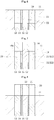
FIG. 1 is a sectional view for illustrating a sintered bearing according to an embodiment of the present invention. -
FIG. 2 is a bottom view for illustrating the sintered bearing. -
FIG. 3 is a sectional view for illustrating a state in which mixed metal powder for an outer layer is filled in a compression molding step among steps of manufacturing the sintered bearing. -
FIG. 4 is a sectional view for illustrating a state in which mixed metal powder for an inner layer is filled in the compression molding step. -
FIG. 5 is a sectional view for illustrating a state in which a partition plate is lowered in the compression molding step. -
FIG. 6 is a sectional view for illustrating a state in which a surplus of the metal powder is removed in the compression molding step. -
FIG. 7 is a sectional view for illustrating a state in which the mixed metal powders are compressed by an upper punch in the compression molding step. -
FIG. 8 is a sectional view for illustrating a state in which a compact is taken out of a die assembly in the compression molding step. -
FIG. 9 is a sectional view for illustrating a state in which a core rod is inserted along an inner periphery of a sintered body in a sizing step for the sintered bearing. -
FIG. 10 is a sectional view for illustrating a state in which the sintered bearing is press-fitted into a die in the sizing step. -
FIG. 11 is a sectional view for illustrating a state in which the sintered bearing is taken out of the die in the sizing step. -
FIG. 12 is a sectional view for illustrating a fluid dynamic bearing device comprising the sintered bearing. -
FIG. 13 is a sectional view for illustrating a spindle motor comprising the fluid dynamic bearing device. - As illustrated in
FIG. 1 and FIG. 2 , asintered bearing 1 according to an embodiment of the present invention integrally comprises aninner layer 2 and anouter layer 3 each made of sintered metal and formed into a cylindrical shape (circular cylindrical shape in the illustrated example). In the illustrated example, thesintered bearing 1 is formed only of theinner layer 2 and theouter layer 3, and an outer peripheral surface of theinner layer 2 and an inner peripheral surface of theouter layer 3 are held in direct contact with each other. The following description is given with reference to a vertical direction of the drawing sheets. However, the following description is not intended to limit a mode of use of thesintered bearing 1. - The
inner layer 2 is made of a material that is relatively likely to be plastically deformed, that is, a material having relatively low compressive yield strength. In this embodiment, theinner layer 2 is made of copper-based or copper-iron-based sintered metal. Specifically, theinner layer 2 is made of sintered metal containing 50 wt% or more (for example, 60 wt%) of copper or copper alloy, and 30 wt% or more (for example, 40 wt%) of iron or iron alloy (such as stainless steel). - The
outer layer 3 is made of a material that is relatively less likely to be plastically deformed, that is, a material having compressive yield strength higher than that of theinner layer 2. In this embodiment, theouter layer 3 is made of sintered metal having a composition different from that of theinner layer 2. Specifically, theouter layer 3 is made of iron-based sintered metal, in particular, sintered metal containing 70 wt% or more of iron. - Dynamic pressure generating grooves serving as a radial dynamic pressure generating portion are formed in an inner peripheral surface 1a of the sintered bearing 1 (that is, in an inner peripheral surface of the inner layer 2). In this embodiment, in the inner peripheral surface 1a of the
sintered bearing 1, dynamic pressure generating grooves 1a1 and 1a2 having a herringbone pattern are formed at two positions separated from each other in an axial direction. The upper dynamic pressure generating grooves 1a1 have an asymmetric pattern in the axial direction. Specifically, in the dynamic pressure generating grooves 1a1, an axial dimension L1 of an upper region with respect to an annular portion formed in a substantially axial center portion of a hill region (region indicated by cross-hatching inFIG. 1 ) is larger than an axial dimension L2 of a lower region with respect to the annular portion (L1>L2). Meanwhile, the lower dynamic pressure generating grooves 1a2 have a symmetric pattern in the axial direction. - An outer
peripheral surface 1b of the sintered bearing 1 (that is, an outer peripheral surface of the outer layer 3) is formed into a smooth circular cylindrical surface. A plurality of (three in the illustrated example) axial grooves 1b1 arranged equiangularly are formed in the outerperipheral surface 1b of the sintered bearing 1 (seeFIG. 2 ). Anupper end surface 1c of thesintered bearing 1 is formed into a flat surface. Dynamic pressure generating grooves 1d1 serving as thrust dynamic pressure generating portions and having a spiral pattern are formed in alower end surface 1d of the sintered bearing 1 (seeFIG. 2 ). - A radial dimension (thickness) of the
outer layer 3 is larger than a radial dimension (thickness) of theinner layer 2. It is only necessary that theinner layer 2 have a minimum thickness enabling forming of the dynamic pressure generating grooves 1a1 and 1a2. For example, the thickness of theinner layer 2 is equal to or smaller than 10% of a thickness of thesintered bearing 1, preferably equal to or smaller than 5% of the thickness of thesintered bearing 1. In the illustrated example, theinner layer 2 is formed within a radial region of chamfered portions formed at both upper and lower ends of the inner peripheral surface 1a of thesintered bearing 1. Thus, an entire region of the inner peripheral surface 1a of thesintered bearing 1 is formed of theinner layer 2, whereas entire regions of the outerperipheral surface 1b and bothend surfaces sintered bearing 1 are formed of theouter layer 3. - Next, a method of manufacturing the above-mentioned
sintered bearing 1 is described. Thesintered bearing 1 is manufactured through a compression molding step, a sintering step, a sizing step, and an oil impregnating step. Now, each step is described. - The compression molding step is performed by so-called two-color molding in which a material for the
inner layer 2 and a material for theouter layer 3 are fed into the same die assembly to be integrally molded. As illustrated inFIG. 3 , a die assembly to be used in the compression molding step comprises a die 11, acore rod 12 arranged along an inner periphery of the die 11, an outerlower punch 13 arranged between an innerperipheral surface 11a of thedie 11 and an outerperipheral surface 12a of thecore rod 12, apartition plate 14, an innerlower punch 15, and an upper punch 16 (seeFIG. 7 ). Forming patterns (not shown) for formation of form axial grooves in an outer peripheral surface of a compact 20 (seeFIG. 7 ) are formed in the inner peripheral surface of thedie 11. The outerlower punch 13, thepartition plate 14, and the innerlower punch 15 are formed into coaxial circular cylindrical shapes, and can be raised and lowered independently of each other. - In the compression molding step, first, as illustrated in
FIG. 3 , thepartition plate 14 and the innerlower punch 15 are raised to an upper end position, and the outerlower punch 13 is lowered to a lower end position. Thus, the innerperipheral surface 11a of the die 11, an outerperipheral surface 14a of thepartition plate 14, and anend surface 13a of the outerlower punch 13 define anouter cavity 17 having a circular cylindrical shape. First mixed metal powder M1 for formation of theouter layer 3 is filled into theouter cavity 17. The first mixed metal powder M1 according to this embodiment is obtained by mixing tin powder or graphite powder with iron powder as needed. As iron powder of the first mixed metal powder M1, there may be used reduced iron powder, atomized iron powder, or electrolytic iron powder. - Next, as illustrated in
FIG. 4 , the innerlower punch 15 is lowered to the lower end position. Thus, an innerperipheral surface 14b of thepartition plate 14, the outerperipheral surface 12a of thecore rod 12, and anend surface 15a of the innerlower punch 15 define aninner cavity 18 having a circular cylindrical shape. Second mixed metal powder M2 for formation of theinner layer 2 is filled into theinner cavity 18. At this time, the second mixed metal powder M2 is caused to overflow theinner cavity 18 so as to cover an upper side of thepartition plate 14. The second mixed metal powder M2 according to this embodiment is obtained by mixing tin powder or graphite powder with iron powder and with copper powder or copper alloy powder as needed. As iron powder of the second mixed metal powder M2, there may be used reduced iron powder, atomized iron powder, or electrolytic iron powder. As copper powder of the second mixed metal powder M2, there may be used electrolytic copper powder or atomized copper powder. As copper alloy powder of the second mixed metal powder M2, there may be used diffusion alloyed copper powder obtained through diffusion bonding of copper and an alloy component, or atomized alloyed copper powder obtained through alloying of copper and an alloy component by an atomizing method. - Next, as illustrated in
FIG. 5 , thepartition plate 14 is lowered. In this manner, the second mixed metal powder M2 enters a space corresponding to thepartition plate 14 so that the first mixed metal powder M1 and the second mixed metal powder M2 come into contact with each other. Thus, in a two-layer state, the first mixed metal powder M1 and the second mixed metal powder M2 fill acavity 19 defined by the innerperipheral surface 11a of the die 11, theend surface 13a of the outerlower punch 13, anend surface 14c of thepartition plate 14, theend surface 15a of the innerlower punch 15, and the outerperipheral surface 12a of thecore rod 12. After that, a surplus of the second mixed metal powder M2 overflowing thecavity 19 is removed (seeFIG. 6 ). - Then, as illustrated in
FIG. 7 , theupper punch 16 is lowered so as to compress from above, by anend surface 16a of theupper punch 16, the mixed metal powders M1 and M2 filled in thecavity 19, thereby forming the compact 20 comprising anouter layer 21 made of the first mixed metal powder M1 and aninner layer 22 made of the second mixed metal powder M2. Then, as illustrated inFIG. 8 , the outerlower punch 13, thepartition plate 14, and the innerlower punch 15 are raised, to thereby take the compact 20 out of the die assembly. An inner peripheral surface of the compact 20 is formed into a circular cylindrical surface, and both end surfaces of the compact 20 are each formed into a flat surface. Further, the axial grooves (not shown) are formed in the outer peripheral surface of the compact 20, and the chamfered portions (not shown) are formed in both upper and lower ends of the inner peripheral surface and the outer peripheral surface of the compact 20. - In the sintering step, the compact 20 is sintered at a predetermined temperature (for example, 870°C), to thereby obtain a sintered body 30 (see
FIG. 9 ) comprising anouter layer 31 and aninner layer 32. - In the sizing step, the
sintered body 30 is formed to have predetermined dimensions, and the dynamic pressure generating grooves are die-formed in an innerperipheral surface 33 and oneaxial end surface 34 of thesintered body 30. In this embodiment, the sizing step is performed under a state in which thesintered bearing 1 illustrated inFIG. 1 is vertically inverted. Further, inFIG. 9 to FIG. 11 , groove depths of forming patterns 41a1 and 41a2 and groove depths of the dynamic pressure generating grooves 1a1 and 1a2 are illustrated in an exaggerated manner. - First, as illustrated in
FIG. 9 , acore rod 41 is inserted along an inner periphery of thesintered body 30. The forming patterns 41a1 and 41a2 having shapes corresponding to the dynamic pressure generating grooves 1a1 and 1a2 are formed in an outer peripheral surface of thecore rod 41. A radial gap is defined between the innerperipheral surface 33 of thesintered body 30 and the outer peripheral surface of thecore rod 41. - Then, as illustrated in
FIG. 10 , thesintered body 30 is pushed downward by anupper punch 42, and is press-fitted to an inner periphery of adie 43 under a state in which thecore rod 41 remains inserted along the inner periphery of thesintered body 30. In this manner, thesintered body 30 is compressed from an outer periphery thereof by thedie 43, and the innerperipheral surface 33 of thesintered body 30 is pressed onto the forming patterns 41a1 and 41a2 of thecore rod 41. Consequently, the innerperipheral surface 33 of thesintered body 30 is plastically deformed, to thereby die-form the dynamic pressure generating grooves 1a1 and 1a2 in the innerperipheral surface 33. At this time, theinner layer 32 of thesintered body 30 is made of the material having relatively low compressive yield strength (copper-iron-based sintered metal in this embodiment), that is, the material that is likely to be plastically deformed. Accordingly, the dynamic pressure generating grooves 1a1 and 1a2 can be reliably die-formed in the innerperipheral surface 33 of thesintered body 30 by pressing the forming patterns 41a1 and 41a2 onto theinner layer 32 and plastically deforming theinner layer 32. - At the same time, a forming pattern (not shown) formed in a
lower surface 42a of theupper punch 42 is pressed onto theend surface 34 of thesintered body 30, to thereby plastically deform theend surface 34. In this manner, the dynamic pressure generating grooves 1d1 (seeFIG. 2 ) are die-formed in theend surface 34. Then, theupper punch 42 is lowered to a predetermined height, and is stopped after completion of press-fitting of thesintered body 30 into thedie 43. In the above-mentioned manner, thesintered body 30 is formed to have the predetermined dimensions, and the dynamic pressure generating grooves 1a1, 1a2, and 1d1 are die-formed in thesintered body 30. - After that, as illustrated in
FIG. 11 , under the state in which thecore rod 41 remains inserted along the inner periphery of thesintered body 30, thesintered body 30 is pushed upward by alower punch 44 to be taken out from the inner periphery of thedie 43. In this manner, thesintered body 30 is released from a compressive force that is inwardly applied to thesintered body 30 by thedie 43, and thesintered body 30 is increased in diameter. As a result, the innerperipheral surface 33 of thesintered body 30 is separated from the outer peripheral surface of thecore rod 41. At this time, theouter layer 31 of thesintered body 30 is made of the material having relatively high compressive yield strength (iron-based sintered metal in this embodiment), that is, a material having a wide elastic region. Accordingly, even when a degree of compressing thesintered body 30 by thedie 43 is increased by increasing a dimensional difference (press-fitting tolerance P, seeFIG. 9 ) between an outer diameter of thesintered body 30 and an inner diameter of the die 43, thesintered body 30 can be elastically restored through spring back. When the degree of compressing thesintered body 30 is increased as described above, the groove depths of the dynamic pressure generating grooves 1a1 and 1a2 to be formed in the innerperipheral surface 33 of thesintered body 30 can be increased. The spring back of thesintered body 30 cancels an axially engaged state between the inner peripheral surface 33 (dynamic pressure generating grooves 1a1 and 1a2) of thesintered body 30 and the outer peripheral surface (forming patterns 41a1 and 41a2) of thecore rod 41. After that, thecore rod 41 is pulled out from the inner periphery of thesintered body 30, thereby separating thesintered body 30 from the die assembly. - An oil as lubricating fluid is impregnated into internal pores of the
sintered body 30 subjected to the sizing step in the above-mentioned manner. Thus, thesintered bearing 1 is completed. - The above-mentioned
sintered bearing 1 is incorporated into, for example, a fluiddynamic bearing device 50 illustrated inFIG. 12 . The fluiddynamic bearing device 50 mainly comprises thesintered bearing 1, ashaft member 52 inserted along the inner periphery of thesintered bearing 1, acylindrical housing 57 in which thesintered bearing 1 is fixed along an inner peripheral surface of thehousing 57, alid member 59 configured to close an opening portion of thehousing 57 on one axial end side thereof, and aseal portion 58 formed at an opening portion of thehousing 57 on another axial end side thereof. In this embodiment, thehousing 57 and theseal portion 58 are formed integrally with each other. - The
shaft member 52 is made of a metal material such as stainless steel, and comprises ashaft portion 52a, and aflange portion 52b formed at a lower end of theshaft portion 52a. - The
housing 57 is made of a resin or metal. In this embodiment, thehousing 57 is formed by injection molding of a resin together with theseal portion 58. Thehousing 57 has a circular cylindrical shape having openings formed in both axial ends thereof. An inner peripheral surface of thehousing 57 comprises a small-diameter innerperipheral surface 57a, and a large-diameter innerperipheral surface 57b formed below the small-diameter innerperipheral surface 57a and having a diameter larger than that of the small-diameter innerperipheral surface 57a. The outerperipheral surface 1b of thesintered bearing 1 is fixed on the small-diameter innerperipheral surface 57a by an appropriate measure such as bonding or press-fitting. An outerperipheral surface 59b of thelid member 59 is fixed on the large-diameter innerperipheral surface 57b by an appropriate measure such as bonding or press-fitting. - The
lid member 59 is made of metal or a resin, and is formed into a disk shape. In anupper end surface 59a of thelid member 59, dynamic pressure generating grooves (not shown) having a spiral pattern are formed. - The
seal portion 58 is formed in the opening portion of thehousing 57 at the upper end thereof. An innerperipheral surface 58a of theseal portion 58 has a tapered shape extending upward to be gradually increased in diameter. Between the innerperipheral surface 58a of theseal portion 58 and an outer peripheral surface 52a1 of theshaft portion 52a, a seal space S is formed to have a wedge-shaped cross-section extending downward to be gradually decreased in radial width. - An oil is injected into the fluid
dynamic bearing device 50 comprising the above-mentioned components. In this manner, an internal space of thehousing 57 including the internal pores of thesintered bearing 1 is filled with the oil, and an oil surface is always maintained within the seal space S. - When the
shaft member 52 is rotated, a radial bearing gap is defined between the inner peripheral surface 1a (region where the dynamic pressure generating grooves 1a1 and 1a2 are formed) of thesintered bearing 1 and the outer peripheral surface 52a1 of theshaft portion 52a. Further, a pressure of an oil film in the radial bearing gap is increased by the dynamic pressure generating grooves 1a1 and 1a2. Owing to this dynamic pressure generating action, there are formed a first radial bearing portion R1 and a second radial bearing portion R2 configured to rotatably support theshaft portion 52a in a non-contact manner. - At the same time, thrust bearing gaps are defined between an upper end surface 52b1 of the
flange portion 52b and thelower end surface 1d (region where the dynamic pressure generating grooves 1d1 are formed) of thesintered bearing 1, and between a lower end surface 52b2 of theflange portion 52b and theupper end surface 59a (region where the dynamic pressure generating grooves are formed) of thelid member 59. Further, a pressure of an oil film in each of the thrust bearing gaps is increased by the dynamic pressure generating grooves 1d1 of thesintered bearing 1 and the dynamic pressure generating grooves of thelid member 59. Owing to this dynamic pressure generating action, there are formed a first thrust bearing portion T1 and a second thrust bearing portion T2 configured to rotatably support theflange portion 52b in both thrust directions in a non-contact manner. - At this time, it is preferred that a size of the radial bearing gap defined between the inner peripheral surface 1a of the
sintered bearing 1 and the outer peripheral surface 52a1 of theshaft portion 52a be equivalent to the groove depths of the dynamic pressure generating grooves 1a1 and 1a2 formed in the inner peripheral surface 1a of the sintered bearing 1 (for example, 0.8 to 1.2 times larger than the groove depths of the dynamic pressure generating grooves 1a1 and 1a2). This is because this configuration maximizes the pressure of the oil film generated in the radial bearing gap to increase bearing rigidity in a radial direction. In this embodiment, as described above, theouter layer 3 having high compressive yield strength is formed in thesintered bearing 1. Thus, an amount of the springback of thesinteredbody 30 is increased, and the dynamic pressure generating grooves 1a1 and 1a2 having the large groove depths are formed owing to the increase in the spring back. The size of the radial bearing gap can be increased in accordance with the increase in the groove depths of the dynamic pressure generating grooves 1a1 and 1a2. Accordingly, torque increase and rubbing between the inner peripheral surface 1a of thesintered bearing 1 and the outer peripheral surface 52a1 of theshaft portion 52a can be avoided. Further, theinner layer 2 having low compressive yield strength is formed in thesintered bearing 1. With this configuration, theinner layer 2 is likely to be plastically deformed, and the dynamic pressure generating grooves 1a1 and 1a2 can be reliably formed. Accordingly, the pressure of the oil film in the radial bearing gap can be efficiently increased, thereby being capable of improving the bearing rigidity. - The above-mentioned fluid
dynamic bearing device 50 is incorporated into, for example, a spindle motor illustrated inFIG. 13 . The spindle motor is used for a disk drive such as an HDD. The spindle motor comprises the fluiddynamic bearing device 50, adisk hub 53 fixed to theshaft member 52 of the fluiddynamic bearing device 50, adrive unit 54 comprising astator coil 54a and arotor magnet 54b, and abracket 55. Thestator coil 54a is fixed to thebracket 55, and therotor magnet 54b is fixed to thedisk hub 53. The fluiddynamic bearing device 50 is fixed on an inner periphery of thebracket 55. Thedisk hub 53 holds a predetermined number of disks 56 (two disks in the illustrated example). When thestator coil 54a is energized, therotor magnet 54b is rotated, thereby causing thedisks 56 held on thedisk hub 53 to rotate integrally with theshaft member 52. - The present invention is not limited to the above-mentioned embodiment. For example, in the above-mentioned embodiment, description is given of the case where the
inner layer 2 and theouter layer 3 of thesintered bearing 1 are made of different materials so that theinner layer 2 and theouter layer 3 are different from each other in compressive yield strength. However, the present invention is not limited thereto. For example, density of theinner layer 2 may be set to be lower than density of theouter layer 3 so that theinner layer 2 and theouter layer 3 are different from each other in compressive yield strength. For example, a grain diameter (such as an average grain diameter) of metal powder for theouter layer 3 is set to be larger than a grain diameter of metal powder for theinner layer 2, thereby setting the density of theouter layer 3 to be higher than the density of theinner layer 2. In this manner, compressive yield strength of theouter layer 3 can be set to be higher than compressive yield strength of theinner layer 2. In this case, theinner layer 2 and theouter layer 3 may be made of sinteredmetal having the same composition. Alternatively, theinner layer 2 and theouter layer 3 may be made of the same materials as those in the above-mentioned embodiment, and the density of theouter layer 3 may be set to be higher than the density of theinner layer 2. - In the above-mentioned embodiment, description is given of the case where, as the radial dynamic pressure generating portion, the dynamic pressure generating grooves 1a1 and 1a2 having a herringbone pattern are formed in the inner peripheral surface 1a of the
sintered bearing 1. However, the present invention is not limited thereto . As the radial dynamic pressure generating portion, dynamic pressure generating grooves having another pattern such as a spiral pattern may be formed. In addition, the radial dynamic pressure generating portion may be formed in a so-called multi-arc bearing comprising a plurality of partial circular cylindrical surfaces connected to one another in a circumferential direction, or in a step bearing having a plurality of axial grooves formed thereinequiangularly. Further,inthe above-mentioned embodiment, the dynamic pressure generating grooves 1a1 and 1a2 are formed in the inner peripheral surface 1a of thesintered bearing 1 at the two positions separated from each other in the axial direction. However, the dynamic pressure generating grooves may be formed continuously in the axial direction, or the dynamic pressure generating grooves may be formed only at one position in the axial direction. - In the above-mentioned embodiment, description is given of the case where the dynamic pressure generating grooves 1d1 having a spiral pattern as the thrust dynamic pressure generating portions are formed in the
end surface 1d of thesintered bearing 1. However, the present invention is not limited thereto. The thrust dynamic pressure generating portions may be constructed of dynamic pressure generating grooves having another shape, such as a herringbone pattern, or step bearings. Further, theend surface 1d of thesintered bearing 1 may be formed into a flat surface, and thrust dynamic pressure generating portions may be formed in the upper end surface 52b1 of theflange portion 52b of theshaft member 52, which is opposed to theend surface 1d of thesintered bearing 1. - The above-mentioned
sintered bearing 1 is applicable not only to the fluiddynamic bearing device 50 of a shaft rotation type, which is configured to support rotation of the shaft member, but also to a fluid dynamic bearing device of a shaft fixing type, in which the shaft member is fixed and thesintered bearing 1 is rotated, or a fluid dynamic bearing device in which both the shaft member and the sintered bearing are rotated. - The above-mentioned
sintered bearing 1 is applicable not only to a spindle motor for an HDD, but also to a spindle motor for other information equipment, a polygon scanner motor for a laser beam printer, a color wheel for a projector, or a fan motor for an electrical apparatus. -
- 1 sintered bearing
- 1a1, 1a2 dynamic pressure generating groove (radial dynamic pressure generating portion)
- 2 inner layer
- 3 outer layer
- 20 compact
- 30 sintered body
- 41 core rod
- 41a1, 41a2 forming pattern
- 42 upper punch
- 43 die
- 44 lower punch
- 50 fluid dynamic bearing device
- 52 shaft member
- 57 housing
- 58 seal portion
- 59 lid member
- R1, R2 radial bearing portion
- T1, T2thrust bearing portion
- S seal space
Claims (7)
- A sintered bearing, comprising:an inner layer and an outer layer each made of sintered metal and formed into a cylindrical shape; anda radial dynamic pressure generating portion die-formed in an inner peripheral surface of the inner layer,wherein the outer layer has compressive yield strength higher than compressive yield strength of the inner layer.
- The sintered bearing according to claim 1, wherein the outer layer has a radial dimension larger than a radial dimension of the inner layer.
- The sintered bearing according to claim 1 or 2, wherein the inner layer is made of copper-iron-based sintered metal, and the outer layer is made of iron-based sintered metal.
- The sintered bearing according to claim 1 or 2, wherein the inner layer has density lower than density of the outer layer.
- The sintered bearing according to claim 4, wherein the inner layer and the outer layer are made of sintered metal having the same composition.
- A fluid dynamic bearing device, comprising:the sintered bearing according to any one of claims 1 to 5; anda shaft member inserted along an inner periphery of the sintered bearing, the shaft member being relatively rotatably supported by dynamic pressure generating action of a fluid film generated in a radial bearing gap defined between an inner peripheral surface of the sintered bearing and an outer peripheral surface of the shaft member.
- A sintered bearing manufacturing method, comprising:a compression molding step of subjecting metal powder to compression molding to form a compact integrally comprising a cylindrical inner layer and an outer layer having compressive yield strength higher than compressive yield strength of the cylindrical inner layer;a sintering step of sintering the compact to form a sintered body; anda sizing step of die-forming a radial dynamic pressure generating portion in an inner peripheral surface of the sintered body,the sizing step comprising:inserting a core rod, which has a forming pattern formed in an outer peripheral surface thereof, along an inner periphery of the sintered body;die-forming the radial dynamic pressure generating portion by press-fitting the sintered body to an inner periphery of a die under a state in which the core rod remains inserted along the inner periphery of the sintered body, compressing the sintered body from an outer periphery thereof to press the inner peripheral surface of the sintered body onto the forming pattern of the core rod, and plastically deforming the inner peripheral surface of the sintered body;separating the inner peripheral surface of the sintered body from the forming pattern of the core rod by taking out the sintered body from the inner periphery of the die under a state in which the core rod remains inserted along the inner periphery of the sintered body to increase the inner peripheral surface of the sintered body in diameter; andseparating the sintered body and the core rod from each other.
Applications Claiming Priority (2)
| Application Number | Priority Date | Filing Date | Title |
|---|---|---|---|
| JP2014077915A JP6461483B2 (en) | 2014-04-04 | 2014-04-04 | Sintered bearing, fluid dynamic pressure bearing device including the same, and method for manufacturing sintered bearing |
| PCT/JP2015/056320 WO2015151698A1 (en) | 2014-04-04 | 2015-03-04 | Sintered bearing, fluid dynamic bearing device provided with same, and sintered bearing manufacturing method |
Publications (2)
| Publication Number | Publication Date |
|---|---|
| EP3128192A1 true EP3128192A1 (en) | 2017-02-08 |
| EP3128192A4 EP3128192A4 (en) | 2018-03-07 |
Family
ID=54240031
Family Applications (1)
| Application Number | Title | Priority Date | Filing Date |
|---|---|---|---|
| EP15772922.9A Withdrawn EP3128192A4 (en) | 2014-04-04 | 2015-03-04 | Sintered bearing, fluid dynamic bearing device provided with same, and sintered bearing manufacturing method |
Country Status (5)
| Country | Link |
|---|---|
| US (1) | US10167899B2 (en) |
| EP (1) | EP3128192A4 (en) |
| JP (1) | JP6461483B2 (en) |
| CN (1) | CN106104031A (en) |
| WO (1) | WO2015151698A1 (en) |
Families Citing this family (4)
| Publication number | Priority date | Publication date | Assignee | Title |
|---|---|---|---|---|
| US10563695B2 (en) * | 2017-04-14 | 2020-02-18 | Tenneco Inc. | Multi-layered sintered bushings and bearings |
| US11248654B2 (en) * | 2017-11-15 | 2022-02-15 | Mitsubishi Materials Corporation | Oil impregnated sintered bearing and production method thereof |
| CN109434080B (en) * | 2018-10-12 | 2020-12-29 | 株洲金韦硬质合金有限公司 | TC bearing assembly sintering method based on precoated sand mold sleeve |
| JP7445233B2 (en) * | 2020-06-09 | 2024-03-07 | 住友電工焼結合金株式会社 | Sizing device and method for producing sintered body |
Family Cites Families (18)
| Publication number | Priority date | Publication date | Assignee | Title |
|---|---|---|---|---|
| US5427456A (en) * | 1994-04-12 | 1995-06-27 | Synektron Corporation | Fluid bearing with asymmetrical groove pattern |
| JP3558768B2 (en) * | 1995-12-26 | 2004-08-25 | 日本電産株式会社 | Motor with hydrodynamic bearing |
| US5941646A (en) * | 1996-12-25 | 1999-08-24 | Ntn Corporation | Hydrodynamic type porous oil-impregnated bearing and bearing device |
| GB2322915B (en) | 1997-03-06 | 2001-06-06 | Ntn Toyo Bearing Co Ltd | Hydrodynamic type porous oil-impregnated bearing |
| JP3607661B2 (en) * | 1997-03-06 | 2005-01-05 | Ntn株式会社 | Hydrodynamic porous oil-impregnated bearing and method for producing the same |
| JP3954695B2 (en) * | 1997-07-18 | 2007-08-08 | Ntn株式会社 | Manufacturing method of dynamic pressure type porous oil-impregnated bearing |
| JP2000224806A (en) * | 1999-01-27 | 2000-08-11 | Toshiba Corp | Hydrodynamic bearing motor |
| CN1189676C (en) * | 2000-07-10 | 2005-02-16 | 株式会社三协精机制作所 | Dynamic pressure bearing device |
| JP2003156048A (en) * | 2001-11-22 | 2003-05-30 | Sony Corp | Fluid bearing and motor |
| JP4204233B2 (en) * | 2002-01-30 | 2009-01-07 | 日立粉末冶金株式会社 | Sintered oil-impregnated plain bearings and construction machinery hydraulic excavators or cranes |
| JP2004270890A (en) * | 2003-03-11 | 2004-09-30 | Nippon Densan Corp | Sleeve of porous sintered material, method for manufacturing the same, and dynamic pressure bearing device using the same sleeve |
| JP2005095979A (en) | 2003-08-29 | 2005-04-14 | Mitsubishi Materials Corp | Powder molding apparatus and green compact manufacturing method |
| JP2008039104A (en) * | 2006-08-08 | 2008-02-21 | Ntn Corp | Fluid bearing device |
| JP2010091002A (en) * | 2008-10-08 | 2010-04-22 | Ntn Corp | Sintered bearing and manufacturing method therefor |
| EP2333366A4 (en) * | 2008-09-05 | 2012-10-10 | Ntn Toyo Bearing Co Ltd | Sintered bearing and process for producing same |
| JP2011021649A (en) * | 2009-07-14 | 2011-02-03 | Ntn Corp | Fluid bearing device |
| JP5674495B2 (en) * | 2011-01-31 | 2015-02-25 | Ntn株式会社 | Fluid dynamic bearing device |
| KR101989837B1 (en) | 2012-03-07 | 2019-06-17 | 엔티엔 가부시키가이샤 | Sintered bearing |
-
2014
- 2014-04-04 JP JP2014077915A patent/JP6461483B2/en not_active Expired - Fee Related
-
2015
- 2015-03-04 CN CN201580014160.4A patent/CN106104031A/en active Pending
- 2015-03-04 WO PCT/JP2015/056320 patent/WO2015151698A1/en not_active Ceased
- 2015-03-04 US US15/301,019 patent/US10167899B2/en not_active Expired - Fee Related
- 2015-03-04 EP EP15772922.9A patent/EP3128192A4/en not_active Withdrawn
Also Published As
| Publication number | Publication date |
|---|---|
| US10167899B2 (en) | 2019-01-01 |
| JP2015200337A (en) | 2015-11-12 |
| WO2015151698A1 (en) | 2015-10-08 |
| JP6461483B2 (en) | 2019-01-30 |
| US20170023059A1 (en) | 2017-01-26 |
| EP3128192A4 (en) | 2018-03-07 |
| CN106104031A (en) | 2016-11-09 |
Similar Documents
| Publication | Publication Date | Title |
|---|---|---|
| JP5384014B2 (en) | Sintered bearing | |
| EP3051156B1 (en) | Sintered metal bearing, fluid-dynamic bearing device provided with said bearing, and fan motor provided with said bearing device | |
| US10167899B2 (en) | Sintered bearing, fluid dynamic bearing device provided with same, and sintered bearing manufacturing method | |
| US10753395B2 (en) | Oil-impregnated sintered bearing and method for manufacturing same | |
| US9732796B2 (en) | Sintered metal bearing and method for producing same | |
| CN107781293B (en) | Dynamic pressure bearing, method of manufacturing the same, fluid dynamic pressure bearing device, motor, and molding die | |
| JP4573349B2 (en) | Manufacturing method of hydrodynamic bearing | |
| JP2011047005A (en) | Method of manufacturing bearing sleeve and fluid dynamic bearing device | |
| EP3118473A1 (en) | Sintered bearing, fluid dynamic bearing device and motor comprising same, and sintered bearing manufacturing method | |
| US12442414B2 (en) | Oil-impregnated sintered bearing and fluid dynamic bearing device provided with the bearing | |
| JP7076266B2 (en) | Manufacturing method of sintered oil-impregnated bearing | |
| US20190078617A1 (en) | Dynamic pressure bearing and method for manufacturing same | |
| JP4172944B2 (en) | Hydrodynamic bearing device and manufacturing method thereof | |
| JP2016180496A (en) | Bearing member and manufacturing method thereof | |
| JP2010091004A (en) | Hydrodynamic pressure bearing device and manufacturing method therefor | |
| JP2006316896A (en) | Method for manufacturing oil-impregnated sintered bearing and oil-impregnated sintered bearing | |
| JP5606831B2 (en) | Bearing member and manufacturing method thereof | |
| JP7713302B2 (en) | Fluid dynamic bearing device | |
| JP4738831B2 (en) | Hydrodynamic bearing device | |
| JP2007100803A (en) | Method for manufacturing oil impregnated sintered bearing, and sizing pin to be used for the method | |
| JP2021001629A (en) | Bearing member and fluid dynamic pressure bearing device including the same | |
| JP2007040482A (en) | Method of manufacturing fluid bearing device | |
| JP2006105331A (en) | Bearing sleeve and its manufacturing method | |
| JP2013044395A (en) | Fluid dynamic-pressure bearing device |
Legal Events
| Date | Code | Title | Description |
|---|---|---|---|
| PUAI | Public reference made under article 153(3) epc to a published international application that has entered the european phase |
Free format text: ORIGINAL CODE: 0009012 |
|
| 17P | Request for examination filed |
Effective date: 20161031 |
|
| AK | Designated contracting states |
Kind code of ref document: A1 Designated state(s): AL AT BE BG CH CY CZ DE DK EE ES FI FR GB GR HR HU IE IS IT LI LT LU LV MC MK MT NL NO PL PT RO RS SE SI SK SM TR |
|
| AX | Request for extension of the european patent |
Extension state: BA ME |
|
| DAV | Request for validation of the european patent (deleted) | ||
| DAX | Request for extension of the european patent (deleted) | ||
| A4 | Supplementary search report drawn up and despatched |
Effective date: 20180205 |
|
| RIC1 | Information provided on ipc code assigned before grant |
Ipc: B22F 7/00 20060101ALI20180130BHEP Ipc: F16C 33/14 20060101ALI20180130BHEP Ipc: F16C 33/12 20060101AFI20180130BHEP Ipc: B22F 7/06 20060101ALI20180130BHEP Ipc: F16C 17/02 20060101ALI20180130BHEP Ipc: B22F 3/24 20060101ALI20180130BHEP |
|
| 17Q | First examination report despatched |
Effective date: 20190322 |
|
| GRAP | Despatch of communication of intention to grant a patent |
Free format text: ORIGINAL CODE: EPIDOSNIGR1 |
|
| INTG | Intention to grant announced |
Effective date: 20191021 |
|
| STAA | Information on the status of an ep patent application or granted ep patent |
Free format text: STATUS: THE APPLICATION IS DEEMED TO BE WITHDRAWN |
|
| 18D | Application deemed to be withdrawn |
Effective date: 20200303 |