EP3128108A1 - Handle unit - Google Patents
Handle unit Download PDFInfo
- Publication number
- EP3128108A1 EP3128108A1 EP16175987.3A EP16175987A EP3128108A1 EP 3128108 A1 EP3128108 A1 EP 3128108A1 EP 16175987 A EP16175987 A EP 16175987A EP 3128108 A1 EP3128108 A1 EP 3128108A1
- Authority
- EP
- European Patent Office
- Prior art keywords
- cap
- handle unit
- fastening element
- guide
- guide surface
- Prior art date
- Legal status (The legal status is an assumption and is not a legal conclusion. Google has not performed a legal analysis and makes no representation as to the accuracy of the status listed.)
- Granted
Links
Images


Classifications
-
- E—FIXED CONSTRUCTIONS
- E05—LOCKS; KEYS; WINDOW OR DOOR FITTINGS; SAFES
- E05B—LOCKS; ACCESSORIES THEREFOR; HANDCUFFS
- E05B17/00—Accessories in connection with locks
- E05B17/14—Closures or guards for keyholes
- E05B17/18—Closures or guards for keyholes shaped as lids or slides
- E05B17/183—Closures or guards for keyholes shaped as lids or slides pivoting outwardly
-
- E—FIXED CONSTRUCTIONS
- E05—LOCKS; KEYS; WINDOW OR DOOR FITTINGS; SAFES
- E05B—LOCKS; ACCESSORIES THEREFOR; HANDCUFFS
- E05B17/00—Accessories in connection with locks
- E05B17/14—Closures or guards for keyholes
-
- E—FIXED CONSTRUCTIONS
- E05—LOCKS; KEYS; WINDOW OR DOOR FITTINGS; SAFES
- E05B—LOCKS; ACCESSORIES THEREFOR; HANDCUFFS
- E05B77/00—Vehicle locks characterised by special functions or purposes
- E05B77/34—Protection against weather or dirt, e.g. against water ingress
-
- E—FIXED CONSTRUCTIONS
- E05—LOCKS; KEYS; WINDOW OR DOOR FITTINGS; SAFES
- E05B—LOCKS; ACCESSORIES THEREFOR; HANDCUFFS
- E05B81/00—Power-actuated vehicle locks
- E05B81/54—Electrical circuits
- E05B81/90—Manual override in case of power failure
-
- E—FIXED CONSTRUCTIONS
- E05—LOCKS; KEYS; WINDOW OR DOOR FITTINGS; SAFES
- E05B—LOCKS; ACCESSORIES THEREFOR; HANDCUFFS
- E05B85/00—Details of vehicle locks not provided for in groups E05B77/00 - E05B83/00
- E05B85/06—Lock cylinder arrangements
-
- E—FIXED CONSTRUCTIONS
- E05—LOCKS; KEYS; WINDOW OR DOOR FITTINGS; SAFES
- E05B—LOCKS; ACCESSORIES THEREFOR; HANDCUFFS
- E05B85/00—Details of vehicle locks not provided for in groups E05B77/00 - E05B83/00
- E05B85/10—Handles
- E05B85/14—Handles pivoted about an axis parallel to the wing
- E05B85/16—Handles pivoted about an axis parallel to the wing a longitudinal grip part being pivoted at one end about an axis perpendicular to the longitudinal axis of the grip part
-
- E—FIXED CONSTRUCTIONS
- E05—LOCKS; KEYS; WINDOW OR DOOR FITTINGS; SAFES
- E05B—LOCKS; ACCESSORIES THEREFOR; HANDCUFFS
- E05B79/00—Mounting or connecting vehicle locks or parts thereof
- E05B79/02—Mounting of vehicle locks or parts thereof
- E05B79/06—Mounting of handles, e.g. to the wing or to the lock
-
- Y—GENERAL TAGGING OF NEW TECHNOLOGICAL DEVELOPMENTS; GENERAL TAGGING OF CROSS-SECTIONAL TECHNOLOGIES SPANNING OVER SEVERAL SECTIONS OF THE IPC; TECHNICAL SUBJECTS COVERED BY FORMER USPC CROSS-REFERENCE ART COLLECTIONS [XRACs] AND DIGESTS
- Y10—TECHNICAL SUBJECTS COVERED BY FORMER USPC
- Y10T—TECHNICAL SUBJECTS COVERED BY FORMER US CLASSIFICATION
- Y10T70/00—Locks
- Y10T70/70—Operating mechanism
- Y10T70/7441—Key
- Y10T70/7915—Tampering prevention or attack defeating
- Y10T70/7955—Keyhole guards
- Y10T70/796—Portable
-
- Y—GENERAL TAGGING OF NEW TECHNOLOGICAL DEVELOPMENTS; GENERAL TAGGING OF CROSS-SECTIONAL TECHNOLOGIES SPANNING OVER SEVERAL SECTIONS OF THE IPC; TECHNICAL SUBJECTS COVERED BY FORMER USPC CROSS-REFERENCE ART COLLECTIONS [XRACs] AND DIGESTS
- Y10—TECHNICAL SUBJECTS COVERED BY FORMER USPC
- Y10T—TECHNICAL SUBJECTS COVERED BY FORMER US CLASSIFICATION
- Y10T70/00—Locks
- Y10T70/70—Operating mechanism
- Y10T70/7441—Key
- Y10T70/7915—Tampering prevention or attack defeating
- Y10T70/7955—Keyhole guards
- Y10T70/7977—Key-controlled
- Y10T70/7983—Portable
-
- Y—GENERAL TAGGING OF NEW TECHNOLOGICAL DEVELOPMENTS; GENERAL TAGGING OF CROSS-SECTIONAL TECHNOLOGIES SPANNING OVER SEVERAL SECTIONS OF THE IPC; TECHNICAL SUBJECTS COVERED BY FORMER USPC CROSS-REFERENCE ART COLLECTIONS [XRACs] AND DIGESTS
- Y10—TECHNICAL SUBJECTS COVERED BY FORMER USPC
- Y10T—TECHNICAL SUBJECTS COVERED BY FORMER US CLASSIFICATION
- Y10T70/00—Locks
- Y10T70/80—Parts, attachments, accessories and adjuncts
- Y10T70/8432—For key-operated mechanism
- Y10T70/8649—Keyhole covers
Definitions
- the invention is directed to a handle unit for a movable part of a vehicle, in particular for a door or a flap, with a movable handle element for opening and / or closing a provided on the movable part lock, a lock cylinder, by means of a cap to the outside is protected, and a fastener to which the cap is detachably arranged, wherein the fastener at least one elastic latching hook and the cap have at least one latching recess, and wherein the at least one latching hook is complementary to the at least one latching recess and with this in a detent position the cap is engaged.
- a grip unit of the type described input is for example from the DE 10 2008 031 218 known.
- Such a modern handle unit for doors or flaps of a vehicle is operated predominantly via electronic means by radio, by infrared or by means of RFID technology. Therefore, the conventional mechanical lock cylinder of the handle unit is only of secondary importance.
- cover caps are known, which are releasably secured to the handle unit or to the cylinder housing of the lock cylinder.
- the cover caps the lock cylinder towards the outside of the handle unit or the door of the vehicle and must then be removed or disassembled when the door or Flap through the lock cylinder with a mechanical key must be opened.
- a tool is required, which is realized in many cases by the mechanical key.
- the invention has for its object to provide a solution that provides a handle unit in a structurally simple manner and cost, which avoids the known from the prior art problem of damage to the vehicle panel and is made possible by the improved attachment to a part of the handle unit.
- the object is achieved in that the cap has on the inside at least one guide lug, which abuts in the detent position on a guide surface which is formed on the fastener and complementary to the guide lug, wherein when loosening the cap Fastening element, the movement of the cap forcibly leads such that moves the at least one guide lug along the complementarily shaped and directed away from the fastener guide surface.
- the expression "positively guided” is to be understood as a movement in which the freedom of movement is restricted at least in one spatial direction and is guided in the manner of a link.
- the term “complementary” means that something is designed to correspond to something else, so that only a corresponding complementary design ensures the functionality.
- the term “complementary” in this sense means that a shape of a component is matched to the shape of another component, just to ensure the desired function in the interaction of the two components.
- the movable part for a vehicle is understood to mean, in particular, an outer door, a side door, a tailgate or a glove box flap or the like.
- the vehicle may in particular be a car, a truck, a ship or an aircraft.
- a handle unit which is characterized by a functional design and has a simple and inexpensive construction. While rests in the detent position of the cap, the guide lug on the guide surface and is supported there, when releasing the cap is a positively driven movement, wherein the guide lug of the cap along the guide surface of the fastener is moved. Due to the fact that the guide surface is directed away from the fastening element, the cover is inevitably moved away from the fastening element and thus away from the handle unit during release, whereby, unlike the grip units known from the prior art, there is no longer the danger that the cap strikes the sheet metal of the door or flap, damaging the paint.
- the specially designed guide surface of the fastener ensures according to the present invention ensures that the cover is led away during disassembly or disassembly of the handle unit from the sheet metal of the door or flap, so that damage to the paint or the sheet is excluded.
- the at least one guide surface of the fastening element and the at least one guide projection of the cover cap are curved in an arc shape. In this way, due to the associated with the arch shape pivoting movement of the cap with relatively little space, the cap can be removed from the handle unit.
- the fastening element has at one of its longitudinal ends a support on which rests at least a portion of a longitudinal end of the cap. Depending on the orientation of the guide surface of the fastener can thereby be realized either a pulling or pivoting movement to release the cap from the handle unit.
- the support and the at least one guide surface which is arranged adjacent to the support and extends substantially parallel to this, together form a pivot bearing for the cover, around which the cover is pivotally mounted to the lock cylinder. Consequently, the cap can be swung open to release the underlying lock cylinder, without causing the risk that the cap could damage the paint or the sheet metal of the door or flap.
- the invention provides in an advantageous manner that the fastening element has at least tworatisbegrenzungsstege, between which at least one movement limiting approach of the cap is arranged, wherein the at least two movement limiting webs movement of the cap transverse to the direction of forcibly guided movement when loosening the Block the cap.
- the invention provides in a further embodiment of the handle unit in that at least one elastically movable locking arm is formed in the interior of the cap, which engages with a locking recess which is formed on the fastening element and complementary to the locking arm of the cap in such a way that a movement the guide lug is blocked along the guide surface.
- the cap is arranged in the detent position when the locking arm is engaged with the locking recess.
- a particularly compact and space-saving design is given in an embodiment of the invention in that the fastening element has a housing for receiving the lock cylinder.
- an arcuate guide surface may be provided a rectilinear guide surface
- a secondary guide projection in the center of the cap or on a guide approach opposite Longitudinal end of the cap is formed, wherein the fastening element has a secondary guide surface which is complementary to the secondary guide lug and from which the secondary guide lug is guided when releasing the cap.
- the invention provides that the fastener is releasably secured to a handle support of the handle unit or is formed as a component portion of a handle support of the handle unit.
- the variant of the component section is to be understood as an embodiment in which the fastening element is formed integrally with the grip carrier.
- the invention provides in a further embodiment of the handle unit, that in the cap, an opening is introduced, through which a tool in the interior of the cap is hineinlimbar so that the at least one elastic latching hook can be pressed out of its detent position that the latching hook except Engagement with the recess passes and the cap is detachable from the handle unit.
- the tool can move the latching recess away from the latching hook, which implies that the latching recess is formed on an elastically movable component.
- the tool passes through the opening in the interior of the cap to release a locking connection between the cap and fastener for disassembly of the cap.
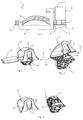
- FIG. 1 shows an arrangement of a handle unit 1 within a door 2 of a motor vehicle, wherein the door 2 is indicated as a painted sheet metal outer skin of the motor vehicle with a dashed line.
- the handle unit 1 has a handle support 3, which is introduced substantially inside the door 2.
- the door 2 has a plurality of openings and passages, so that the operating elements of the handle unit 1 are attached to the outside of the door 2 and can be connected to the handle support 3 through the openings.
- FIGS. 1 to 12 in which a first embodiment of the handle unit 1 according to the invention is shown, is provided as an operating element designed in the manner of a handle handle element 4 for manual operation of the handle unit 1.
- the grip element 4 cooperates with a lock cylinder 5, so that when the lock cylinder 5 is locked, the grip element 4 can not be operated effectively.
- the lock cylinder 5 is arranged on the inside in the door 2 of the motor vehicle and is accommodated in a cylinder housing 6, which is integrally formed with a fastening element 7. With the help of the fastener 7 of the lock cylinder 5 can be fastened to the handle support 3. For example, a power failure, a mechanical key 8 can be used to operate the lock cylinder.
- a cap 9 is provided, which is arranged in extension of the grip element 4 and which is adapted to the shape of the grip element 4.
- the attachment of the cap 9 is concealed and implemented via internal locking geometries, as will be described in more detail below.
- the cap 9 is arranged on the fastening element 7 releasably attached to the handle unit 1. More specifically, the cap 9 is releasably attached to the fastener 7, wherein in the illustrated embodiment, the fastener 7 itself is releasably secured to the handle support 3. Alternatively, it would also be conceivable that the fastening element 7 as a component portion of the handle support 3, that is integrally formed with the handle support 3. In order for the cover cap 9 to be releasably attachable to the fastening element 7, the fastening element 7 has an elastic latching hook 10. How further the FIGS. 2 to 4 can be seen, in the cap 9 a recess 11 is formed, in which the latching hook 10 engages to the cap 9 in a locking position (see FIG. 2 ) on the fastener 7 set.
- the use of a tool is necessary, which in the present case may be the mechanical key 8 or a similar shaped tool.
- a tool which in the present case may be the mechanical key 8 or a similar shaped tool.
- an opening 12 is formed in the cap 9, through which the mechanical key 8 can be guided into the interior of the cap 9.
- the latching recess 11 which is formed in an elastically movable tab 14, can then be disengaged from the latching hook 10.
- the tab 14 is elastically bent to the side, so that the latching hook 10 passes out of the latching recess 11.
- the cap 9 is at least at the longitudinal end 15, to which the latching recess 11 and the latching hook 10 are formed on the cap 9 and the fastening element 7, relative to the fastening element 7 movable, such as in FIG. 3 is shown in which the released longitudinal end 15 of the cap 9 is moved away from the longitudinal end 15 of the fastener 7. At the other longitudinal end 16, however, the cap 9 is still held on the fastening element 7, wherein at this longitudinal end 16, a guided movement of the cap 9 takes place, as will be described below.
- the cover 9 has on the inside a plurality of guide lugs 17, wherein in the embodiment four guide lugs 17 are present, which extend at the longitudinal end 16 on the inside in the direction of the open side of the cap 9.
- the guide lugs 17 of the cap 9 In the locked position (see for example FIG. 10 ) are the guide lugs 17 of the cap 9 at a formed on the longitudinal end 16 guide surface 18 of the fastener 7 at.
- the guide surface 18 is formed complementary to the shape of the guide lugs 17. If now at the longitudinal end 15 of the latching hook 10 is brought out of engagement with the latching recess 11, then the longitudinal end 15 of the cap 9 can be moved relative to the fastening element 7, as it FIG. 12 shows.
- the complementary design of the guide surface 18 to the guide lugs 17 allows for the release of the cap 9, a forced movement in which the fastener 7, the movement of the cap 9 such leads or forced leads that the guide lugs 17 along the complementary formed and away from the fastener 7 move directed guide surface 18.
- the guide surface 18 of the fastener 7 and the guide lugs 17 of the cap 9 arcuate or curved extending formed, causing the in FIG. 3 and 12 shown pivoting movement of the cap 9 results. This pivoting movement is facilitated by the fact that the fastening element 7 has at its longitudinal end 16 a support 19 on which at least a portion of a longitudinal end 16 of the cap 9 rests.
- the cap 9 is fixed securely in its rest position next to the fixation at the one longitudinal end 15 and at the other longitudinal end 16, inside the cap 9, three elastically deformable locking arms 21 (see, for example FIG. 8 ), which have a hook-shaped free end 23.
- the hook-shaped free ends 23 of the elastic locking arms 21 are in locking position of the Abbdeckkappe 9 in engagement with correspondingly formed in the fastener 7 locking recesses 22.
- the locking recesses 22 are complementary to the three locking arms 21 of the cap 9 in the frame-like structure of the fastener 7 is formed.
- the free hook-shaped ends 23 each have different spatial directions, which favors the fixation of the cap 9.
- the two outer guide lugs 17 simultaneously form the two outer locking arms 21 (see, for example FIG. 11 ), which gives these management approaches a dual function.
- the fastening element 7 also has two movement limiting webs 24 on, between which two movement limiting lugs 25 of the cap 9 are arranged such that a movement of the cap 9 is blocked transversely to the direction of forcibly guided movement when releasing the cap 9 (see FIG. 11 ), whereby tilting of the cap 9 upon release from the handle unit 1 is prevented.
- the two outer locking arms 21 of the cap 9 each form a kind of movement limiting approach 25 (see FIG. 11 ), which in each case abut against corresponding outboard movement limiting webs 24, whereby a tilting of the cap 9 is prevented during their disassembly.
- FIG. 13 a second embodiment of the invention is shown, which differs from the first embodiment in that now an additional guide for the cap 9 is provided.
- This additional guide can be formed either at the longitudinal end 15 and / or the center of the cap 9, as FIG. 13 shows.
- the centrally formed guide is formed by a secondary guide lug 17 'of the cap 9 and a secondary guide surface 18' of the fastener 7, whereas in an additional guide at the longitudinal end 15 of the guide from a secondary guide lug 17 "of the cap 9 and a Secondary guide surface 18 "of the fastener 7 is formed.
- the lugs 17, 17 'and 18, 18', 18 "in this case are not arcuate or curved as in the first embodiment but rectilinear, so that when disassembling a rectilinearly away from the handle unit 1 movement of the cap 9 takes place.
- the second embodiment is quite generally that in addition to the at least one guide lug 17 which is formed at the longitudinal end 16 of the cap 9, the secondary guide lug 17 ', 17 “center of the cap 9 and / or on the guide lug 17 opposite Longitudinal end 15 of the cap 9 is formed, wherein the fastening element 7 has a secondary guide surface 18 ', 18 ", which is complementary to the secondary guide lug 17', 17" is formed and from which the secondary guide lug 17 ', 17 "is performed when loosening the cap 9.
- a handle unit 1 for a movable part of a vehicle in particular for a door 2 or a flap 2, has been described above.
- the handle unit 1 comprises the movable grip element 4 for opening and / or closing a lock provided on the movable part, the lock cylinder 5, which is protected by means of the cover 9 to the outside, and the fastening element 7, on which the cover 9 is detachably arranged ,
- the fastening element 7 has at least one elastic latching hook 10 and the cap 9 at least one latching recess 11, wherein the at least one latching hook 10 is complementary to the at least one latching recess 11 and is engaged with this in a locking position of the cap 9.
- the cap 9 has on the inside at least one guide lug 17, which rests in the latching position on a guide surface 18, which is formed on the fastening element 7 and complementary to the guide lug 17, wherein upon release of the cap 9, the fastening element 7, the movement the cap 9 forcibly leads such that the at least one guide lug 17 moves along the complementarily shaped guide surface 18 directed away from the fastening element 7.
- the advantage to be seen in this embodiment compared to the known from the prior art embodiments is that the cap 9 does not dissolve immediately during disassembly of the handle unit and falls down to the ground.
- the guide also ensures that the pointed longitudinal end of the cap 9 does not move into the metal sheet of the vehicle body and damage the paint or sheet.
- the guide according to the invention ensures that the cap 9 is led away from the sheet.
- the presented invention provides a safer attachment of the cap on the handle unit, as it suggest the known from the prior art solutions. It is understood that not only a guide but also a second or even third guidance can be provided as it is in the FIG. 13 shown embodiment and has been described above.
Landscapes
- Lock And Its Accessories (AREA)
Abstract
Bei einer Griffeinheit (1) mit einem Griffelement (4) zum Öffnen und/oder Schließen eines an einem beweglichen Teil vorgesehenen Schlosses, einem Schließzylinder (5), der mittels einer Abdeckkappe (9) geschützt ist, und einem Befestigungselement (7), an welchem die Abdeckkappe (9) lösbar angeordnet ist, soll eine Lösung geschaffen werden, durch die eine verbesserte Befestigung an einem Teil der Griffeinheit ermöglicht wird. Dies wird dadurch erreicht, dass die Abdeckkappe (9) innenseitig wenigstens einen Führungsansatz (17) aufweist, welcher in der Raststellung an einer Führungsfläche (18) anliegt, die an dem Befestigungselement (7) und komplementär zu dem Führungsansatz (17) ausgebildet ist, wobei beim Lösen der Abdeckkappe (9) das Befestigungselement (7) die Bewegung der Abdeckkappe (9) derart zwangsführt, dass sich der wenigstens eine Führungsansatz (17) entlang der komplementär ausgebildeten und von dem Befestigungselement (7) weg gerichteten Führungsfläche (18) bewegt.In a handle unit (1) with a handle element (4) for opening and / or closing a provided on a movable part lock, a lock cylinder (5), which is protected by a cover (9), and a fastener (7) on in which the cap (9) is detachably arranged, a solution is to be created by which an improved attachment to a part of the handle unit is made possible. This is achieved in that the cover cap (9) has on the inside at least one guide lug (17) which rests in the latching position on a guide surface (18) which is formed on the fastening element (7) and complementary to the guide lug (17), wherein upon release of the cap (9) the fastener (7) forces the movement of the cap (9) such that the at least one guide lug (17) moves along the complementarily shaped and away from the fastener (7) directed guide surface (18) ,
Description
Die Erfindung richtet sich auf eine Griffeinheit für ein bewegliches Teil eines Fahrzeugs, insbesondere für eine Tür oder eine Klappe, mit einem beweglichen Griffelement zum Öffnen und/oder Schließen eines an dem beweglichen Teil vorgesehenen Schlosses, einem Schließzylinder, der mittels einer Abdeckkappe nach außen hin geschützt ist, und einem Befestigungselement, an welchem die Abdeckkappe lösbar angeordnet ist, wobei das Befestigungselement wenigstens einen elastischen Rasthaken und die Abdeckkappe wenigstens eine Rastausnehmung aufweisen, und wobei der wenigstens eine Rasthaken komplementär zu der wenigstens einen Rastausnehmung ausgebildet ist und mit dieser in einer Raststellung der Abdeckkappe in Eingriff steht.The invention is directed to a handle unit for a movable part of a vehicle, in particular for a door or a flap, with a movable handle element for opening and / or closing a provided on the movable part lock, a lock cylinder, by means of a cap to the outside is protected, and a fastener to which the cap is detachably arranged, wherein the fastener at least one elastic latching hook and the cap have at least one latching recess, and wherein the at least one latching hook is complementary to the at least one latching recess and with this in a detent position the cap is engaged.
Eine Griffeinheit der Eingangs bezeichneten Art ist zum Beispiel aus der
Bei Stromausfall oder sonstigen elektronischen Störungen im Kraftfahrzeug muss jedoch eine Möglichkeit erhalten bleiben, das Kraftfahrzeug auch ohne elektronische Mittel zu öffnen. Daher sind nach wie vor zumindest an der Fahrertür Schließzylinder vorgesehen, die jedoch bei einer derartigen Griffeinheit nur sehr selten mit einem mechanischen Schlüssel bedient werden. Um den Schließzylinder zu schützen und von außen zu verdecken, sind Abdeckkappen bekannt, die an der Griffeinheit oder an dem Zylindergehäuse des Schließzylinders lösbar befestigt werden. Die Abdeckkappen verdecken den Schließzylinder in Richtung zur Außenseite der Griffeinheit bzw. der Tür des Fahrzeugs und müssen dann entnommen bzw. demontiert werden, wenn die Tür oder Klappe durch den Schließzylinder mit einem mechanischen Schlüssel geöffnet werden muss. Zur Demontage der Abdeckkappen ist meist ein Werkzeug erforderlich, welches in vielen Fällen durch den mechanischen Schlüssel realisiert ist. Bei der Demontage der Abdeckkappe von der Griffeinheit besteht das Problem, dass die Abdeckkappe unkontrolliert von der Griffeinheit gelöst wird und dabei in Richtung der Tür oder Klappe bzw. in Richtung des Karosserieblechs der Tür oder Klappe bewegt wird und dort anschlägt, was eine Beschädigung des Lacks und/oder des Blechs nach sich ziehen kann.In case of power failure or other electronic disturbances in the motor vehicle, however, must remain a possibility to open the motor vehicle without electronic means. Therefore, locking cylinders are still provided at least at the driver's door, which are very rarely operated with a mechanical key in such a handle unit. To protect the lock cylinder and to conceal it from the outside, cover caps are known, which are releasably secured to the handle unit or to the cylinder housing of the lock cylinder. The cover caps the lock cylinder towards the outside of the handle unit or the door of the vehicle and must then be removed or disassembled when the door or Flap through the lock cylinder with a mechanical key must be opened. For disassembly of the caps usually a tool is required, which is realized in many cases by the mechanical key. When disassembling the cap from the handle unit, there is the problem that the cap is uncontrollably released from the handle unit and is moved in the direction of the door or flap or in the direction of the body panel of the door or flap and strikes there, causing damage to the paint and / or the sheet can entail.
Der Erfindung liegt die Aufgabe zugrunde eine Lösung zu schaffen, die auf konstruktiv einfache Weise und kostengünstig eine Griffeinheit bereitstellt, welche das aus dem Stand der Technik bekannte Problem einer Beschädigung des Fahrzeugblechs vermeidet und durch die eine verbesserte Befestigung an einem Teil der Griffeinheit ermöglicht wird.The invention has for its object to provide a solution that provides a handle unit in a structurally simple manner and cost, which avoids the known from the prior art problem of damage to the vehicle panel and is made possible by the improved attachment to a part of the handle unit.
Bei einer Griffeinheit der Eingangs bezeichneten Art wird die Aufgabe erfindungsgemäß dadurch gelöst, dass die Abdeckkappe innenseitig wenigstens einen Führungsansatz aufweist, welcher in der Raststellung an einer Führungsfläche anliegt, die an dem Befestigungselement und komplementär zu dem Führungsansatz ausgebildet ist, wobei beim Lösen der Abdeckkappe das Befestigungselement die Bewegung der Abdeckkappe derart zwangsführt, dass sich der wenigstens eine Führungsansatz entlang der komplementär ausgebildeten und von dem Befestigungselement weg gerichteten Führungsfläche bewegt. Im Sinne der Erfindung ist unter dem Ausdruck "zwangsgeführt" eine Bewegung zu verstehen, bei welcher die Bewegungsfreiheit zumindest in eine Raumrichtung eingeschränkt ist und nach Art einer Kulisse geführt erfolgt. Ferner ist im Sinne der Erfindung unter dem Ausdruck "komplementär" zu verstehen, dass etwas korrespondierend zu etwas anderem ausgebildet ist, so dass erst eine entsprechende komplementäre Ausbildung die Funktionalität gewährleistet. Dabei meint der Ausdruck "komplementär" in diesem Sinne, dass eine Form eines Bauteils auf die Form eines anderen Bauteils abgestimmt ist, um gerade die gewünschte Funktion im Zusammenspiel beider Bauteile zu gewährleisten. Im Rahmen der vorliegenden Erfindung wird schließlich unter dem beweglichen Teil für ein Fahrzeug insbesondere eine Außentür, eine Seitentür, eine Heckklappe oder eine Handschuhfachklappe oder dergleichen verstanden. Bei dem Fahrzeug kann es sich insbesondere um einen PKW, einen LKW, ein Schiff oder ein Flugzeug handeln.In a handle unit of the type described input, the object is achieved in that the cap has on the inside at least one guide lug, which abuts in the detent position on a guide surface which is formed on the fastener and complementary to the guide lug, wherein when loosening the cap Fastening element, the movement of the cap forcibly leads such that moves the at least one guide lug along the complementarily shaped and directed away from the fastener guide surface. For the purposes of the invention, the expression "positively guided" is to be understood as a movement in which the freedom of movement is restricted at least in one spatial direction and is guided in the manner of a link. Furthermore, for the purposes of the invention, the term "complementary" means that something is designed to correspond to something else, so that only a corresponding complementary design ensures the functionality. The term "complementary" in this sense means that a shape of a component is matched to the shape of another component, just to ensure the desired function in the interaction of the two components. As part of the Finally, in the present invention, the movable part for a vehicle is understood to mean, in particular, an outer door, a side door, a tailgate or a glove box flap or the like. The vehicle may in particular be a car, a truck, a ship or an aircraft.
Vorteilhafte und zweckmäßige Ausgestaltungen und Weiterbildungen der Erfindung ergeben sich aus den Unteransprüchen.Advantageous and expedient refinements and developments of the invention will become apparent from the dependent claims.
Durch die Erfindung wird eine Griffeinheit zur Verfügung gestellt, die sich durch eine funktionsgerechte Konstruktion auszeichnet und einen einfachen und kostengünstigen Aufbau aufweist. Während in der Raststellung der Abdeckkappe der Führungsansatz auf der Führungsfläche aufliegt und sich dort abstützt, erfolgt beim Lösen der Abdeckkappe eine zwangsgeführte Bewegung, bei welcher der Führungsansatz der Abdeckkappe entlang der Führungsfläche des Befestigungselements bewegt wird. Dadurch, dass die Führungsfläche von dem Befestigungselement weg gerichtet ausgebildet ist, wird die Abdeckkappe beim Lösen zwangsläufig von dem Befestigungselement und damit von der Griffeinheit weg bewegt, wodurch im Gegensatz zu den aus dem Stand der Technik bekannten Griffeinheiten nicht länger die Gefahr gegeben ist, dass die Abdeckkappe auf das Blech der Tür oder Klappe anschlägt und dabei den Lack beschädigt. Die besonders ausgestaltete Führungsfläche des Befestigungselements sorgt gemäß der vorliegenden Erfindung dafür, dass die Abdeckkappe beim Lösen bzw. bei Demontage von der Griffeinheit vom Blech der Tür oder Klappe weggeführt wird, so dass eine Beschädigung des Lacks oder des Blechs ausgeschlossen ist.By the invention, a handle unit is provided, which is characterized by a functional design and has a simple and inexpensive construction. While rests in the detent position of the cap, the guide lug on the guide surface and is supported there, when releasing the cap is a positively driven movement, wherein the guide lug of the cap along the guide surface of the fastener is moved. Due to the fact that the guide surface is directed away from the fastening element, the cover is inevitably moved away from the fastening element and thus away from the handle unit during release, whereby, unlike the grip units known from the prior art, there is no longer the danger that the cap strikes the sheet metal of the door or flap, damaging the paint. The specially designed guide surface of the fastener ensures according to the present invention ensures that the cover is led away during disassembly or disassembly of the handle unit from the sheet metal of the door or flap, so that damage to the paint or the sheet is excluded.
Als besonders effektiv hat es sich in Ausgestaltung der erfindungsgemäßen Griffeinheit erwiesen, dass die wenigstens eine Führungsfläche des Befestigungselements und der wenigstens eine Führungsansatz der Abdeckkappe bogenförmig verlaufend ausgebildet sind. Auf diese Weise kann infolge der mit der Bogenform verbundenen Schwenkbewegung der Abdeckkappe mit relativ wenig Platzbedarf die Abdeckkappe von der Griffeinheit demontiert werden.In a refinement of the handle unit according to the invention, it has proven to be particularly effective that the at least one guide surface of the fastening element and the at least one guide projection of the cover cap are curved in an arc shape. In this way, due to the associated with the arch shape pivoting movement of the cap with relatively little space, the cap can be removed from the handle unit.
In Ausgestaltung der Erfindung ist vorgesehen, dass das Befestigungselement an einem seiner Längsenden eine Abstützung aufweist, auf welcher wenigstens ein Abschnitt eines Längsendes der Abdeckkappe aufliegt. Je nach Ausrichtung der Führungsfläche des Befestigungselements kann dadurch entweder eine Zieh- oder Schwenkbewegung realisiert werden, um die Abdeckkappe von der Griffeinheit zu lösen.In an embodiment of the invention it is provided that the fastening element has at one of its longitudinal ends a support on which rests at least a portion of a longitudinal end of the cap. Depending on the orientation of the guide surface of the fastener can thereby be realized either a pulling or pivoting movement to release the cap from the handle unit.
Von besonderem Vorteil ist es, wenn die Abstützung und die wenigstens eine Führungsfläche, die benachbart zu der Abstützung angeordnet ist und im wesentlichen parallel zu dieser verläuft, gemeinsam ein Schwenklager für die Abdeckkappe bilden, um welches die Abdeckkappe verschwenkbar zu dem Schließzylinder gelagert ist. Folglich kann die Abdeckkappe aufgeschwenkt werden, um den darunter liegend angeordneten Schließzylinder freizugeben, ohne dass dabei die Gefahr besteht, dass die Abdeckkappe den Lack oder das Blech der Tür oder Klappe beschädigen könnte.It is particularly advantageous if the support and the at least one guide surface, which is arranged adjacent to the support and extends substantially parallel to this, together form a pivot bearing for the cover, around which the cover is pivotally mounted to the lock cylinder. Consequently, the cap can be swung open to release the underlying lock cylinder, without causing the risk that the cap could damage the paint or the sheet metal of the door or flap.
In weiterer Ausgestaltung der erfindungsgemäßen Griffeinheit sieht die Erfindung in vorteilhafter Weise vor, dass das Befestigungselement wenigstens zwei Bewegungsbegrenzungsstege aufweist, zwischen denen wenigstens ein Bewegungsbegrenzungsansatz der Abdeckkappe angeordnet ist, wobei die wenigstens zwei Bewegungsbegrenzungsstege eine Bewegung der Abdeckkappe quer zur Richtung der zwangsgeführten Bewegung beim Lösen der Abdeckkappe blockieren. Durch die Maßnahme der wenigstens zwei Bewegungsbegrenzungsstege im Zusammenspiel mit dem dazwischen liegend angeordneten Bewegungsbegrenzungsansatz ist eine Bewegung der Abdeckkappe nur entlang einer Richtung, nämlich entlang der Führungsfläche, möglich, nicht aber quer bzw. seitlich zur Führungsfläche.In a further embodiment of the handle unit according to the invention, the invention provides in an advantageous manner that the fastening element has at least two Bewegungsbegrenzungsstege, between which at least one movement limiting approach of the cap is arranged, wherein the at least two movement limiting webs movement of the cap transverse to the direction of forcibly guided movement when loosening the Block the cap. By the measure of the at least two movement limiting webs in interaction with the movement limiting approach arranged therebetween, a movement of the cap is possible only along one direction, namely along the guide surface, but not transversely or laterally to the guide surface.
Die Erfindung sieht in weiterer Ausgestaltung der Griffeinheit vor, dass im Inneren der Abdeckkappe wenigstens ein elastisch bewegbarer Verriegelungsarm ausgebildet ist, der mit einer Verriegelungsausnehmung, die an dem Befestigungselement und komplementär zu dem Verriegelungsarm der Abdeckkappe ausgebildet ist, derart in Eingriff steht, dass eine Bewegung des Führungsansatzes entlang der Führungsfläche blockiert ist. Insbesondere ist die Abdeckkappe in der Raststellung angeordnet, wenn der Verriegelungsarm mit der Verriegelungsausnehmung in Eingriff steht.The invention provides in a further embodiment of the handle unit in that at least one elastically movable locking arm is formed in the interior of the cap, which engages with a locking recess which is formed on the fastening element and complementary to the locking arm of the cap in such a way that a movement the guide lug is blocked along the guide surface. In particular, the cap is arranged in the detent position when the locking arm is engaged with the locking recess.
Eine besonders kompakte und platzsparende Ausführung ist in Ausgestaltung der Erfindung dadurch gegeben, dass das Befestigungselement ein Gehäuse zur Aufnahme des Schließzylinders aufweist.A particularly compact and space-saving design is given in an embodiment of the invention in that the fastening element has a housing for receiving the lock cylinder.
Als alternative zu einer bogenförmig verlaufenden Führungsfläche kann eine geradlinig verlaufende Führungsfläche vorgesehen sein, wobei dann in Ausgestaltung der Erfindung zusätzlich zu dem wenigstens einen Führungsansatz, der an einem Längsende der Abdeckkappe ausgebildet ist, ein Sekundär-Führungsansatz mittig der Abdeckkappe oder an einem dem Führungsansatz gegenüberliegenden Längsende der Abdeckkappe ausgebildet ist, wobei das Befestigungselement eine Sekundär-Führungsfläche aufweist, die komplementär zu dem Sekundär-Führungsansatz ausgebildet ist und von welcher der Sekundär-Führungsansatz beim Lösen der Abdeckkappe geführt ist. Auf diese Weise ist nur eine Bewegung der Abdeckkappe bei Demontage von der Griffeinheit fort oder bei Montage zu dieser hin möglich. Eine Schwenkbewegung oder eine seitliche Bewegung der Abdeckkappe ist hingegen aufgrund der Führungsfläche und der Sekundär-Führungsfläche nicht möglich.As an alternative to an arcuate guide surface may be provided a rectilinear guide surface, then in an embodiment of the invention in addition to the at least one guide lug, which is formed at a longitudinal end of the cap, a secondary guide projection in the center of the cap or on a guide approach opposite Longitudinal end of the cap is formed, wherein the fastening element has a secondary guide surface which is complementary to the secondary guide lug and from which the secondary guide lug is guided when releasing the cap. In this way, only a movement of the cap during disassembly of the handle unit away or when mounting to this point is possible. A pivoting movement or a lateral movement of the cap, however, is not possible due to the guide surface and the secondary guide surface.
Eine kostengünstige Möglichkeit der Ausgestaltung des Befestigungselements sieht die Erfindung darin vor, dass das Befestigungselement an einem Griffträger der Griffeinheit lösbar befestigt ist oder als Bauteilabschnitt eines Griffträgers der Griffeinheit ausgebildet ist. Dabei ist unter der Variante des Bauteilabschnitts eine Ausführungsform zu verstehen, bei welcher das Befestigungselement einstückig mit dem Griffträger ausgebildet ist.An inexpensive way of designing the fastener, the invention provides that the fastener is releasably secured to a handle support of the handle unit or is formed as a component portion of a handle support of the handle unit. Here, the variant of the component section is to be understood as an embodiment in which the fastening element is formed integrally with the grip carrier.
Schließlich sieht die Erfindung in weiterer Ausgestaltung der Griffeinheit vor, dass in der Abdeckkappe eine Öffnung eingebracht ist, durch die ein Werkzeug in das Innere der Abdeckkappe hineinführbar ist, so dass der wenigstens eine elastische Rasthaken derart aus seiner Raststellung drückbar ist, dass der Rasthaken außer Eingriff mit der Rastausnehmung gelangt und die Abdeckkappe von der Griffeinheit lösbar ist. Alternativ kann das Werkzeug die Rastausnehmung von dem Rasthaken weg bewegen, was voraussetzt, dass die Rastausnehmung an einem elastisch bewegbaren Bauteil ausgebildet ist. Allgemein gilt, dass das Werkzeug über die Öffnung in das Innere der Abdeckkappe gelangt, um für die Demontage der Abdeckkappe eine Rastverbindung zwischen Abdeckkappe und Befestigungselement zu lösen.Finally, the invention provides in a further embodiment of the handle unit, that in the cap, an opening is introduced, through which a tool in the interior of the cap is hineinführbar so that the at least one elastic latching hook can be pressed out of its detent position that the latching hook except Engagement with the recess passes and the cap is detachable from the handle unit. Alternatively, the tool can move the latching recess away from the latching hook, which implies that the latching recess is formed on an elastically movable component. In general, the tool passes through the opening in the interior of the cap to release a locking connection between the cap and fastener for disassembly of the cap.
Es versteht sich, dass die vorstehend genannten und nachstehend noch zu erläuternden Merkmale nicht nur in der jeweils angegebenen Kombination, sondern auch in anderen Kombinationen oder in Alleinstellung verwendbar sind, ohne den Rahmen der vorliegenden Erfindung zu verlassen. Der Rahmen der Erfindung ist nur durch die Ansprüche definiert.It is understood that the features mentioned above and those yet to be explained can be used not only in the particular combination given, but also in other combinations or in isolation, without departing from the scope of the present invention. The scope of the invention is defined only by the claims.
Weitere Einzelheiten, Merkmale und Vorteile des Gegenstandes der Erfindung ergeben sich aus der nachfolgenden Beschreibung im Zusammenhang mit der Zeichnung, in der beispielhafte bevorzugte Ausführungsbeispiele der Erfindung dargestellt sind. In der Zeichnung zeigt:
-
Figur 1 eine Schnittdarstellung der Anordnung einer Griffeinheit in einer Tür eines Kraftfahrzeugs mit einem Schließzylinder und einem Befestigungselement, wobei eine an dem Befestigungselement angebrachte Abdeckkappe vorgesehen ist, um den Schließzylinder abzudecken, -
Figur 2 -
Figur 3 eine perspektivische Ansicht auf die von dem Befestigungselement gelöste Abdeckkappe, -
Figur 4Figur 3 gezeigten Bauteile der erfindungsgemäßen Griffeinheit, -
Figur 5Figur 3 in perspektivischer Darstellung, -
Figur 6Figur 3 in perspektivischer Darstellung, -
Figur 7Figur 5 -
Figur 8 eine perspektivische Schnittansicht der Abdeckkappe ausFigur 6 -
Figur 9Figur 5 -
Figur 10 -
Figur 11 -
Figur 12 -
Figur 13 alternative Ausführungsformen mit Sekundär-Führungsfläche und Sekundär-Führungsansatz in schematischer Schnittdarstellung.
-
FIG. 1 a sectional view of the arrangement of a handle unit in a door of a motor vehicle with a lock cylinder and a fastener, wherein a cap attached to the fastener is provided to cover the lock cylinder, -
FIG. 2 attached to the fastener cap and a mechanical key for releasing the cap in perspective view, -
FIG. 3 a perspective view of the solved by the fastener cap, -
FIG. 4 an itemized view of inFIG. 3 shown components of the handle unit according to the invention, -
FIG. 5 from the fastenerFIG. 3 in perspective, -
FIG. 6 the cap offFIG. 3 in perspective, -
FIG. 7 a perspective sectional view of the fastenerFIG. 5 . -
FIG. 8 a perspective sectional view of the capFIG. 6 . -
FIG. 9 another perspective sectional view of the fastenerFIG. 5 . -
FIG. 10 a side sectional view of the fastener and the cap in the locked position, -
FIG. 11 a sectional front view of the fastener and the cap in the locked position, -
FIG. 12 a sectional side view of the fastener and the cap after its release from the fastener and -
FIG. 13 alternative embodiments with secondary guide surface and secondary guide approach in a schematic sectional view.
Mit Bezug auf die
Die Abdeckkappe 9 ist über das Befestigungselement 7 lösbar an der Griffeinheit 1 angeordnet. Genauer gesagt ist die Abdeckkappe 9 lösbar an dem Befestigungselement 7 angebracht, wobei in dem dargestellten Ausführungsbeispiel das Befestigungselement 7 selbst lösbar an dem Griffträger 3 befestigt ist. Alternativ wäre es auch denkbar, dass das Befestigungselement 7 als Bauteilabschnitt des Griffträgers 3, also einstückig mit dem Griffträger 3, ausgebildet ist. Damit die Abdeckkappe 9 an dem Befestigungselement 7 lösbar anbringbar ist, weist das Befestigungselement 7 einen elastischen Rasthaken 10 auf. Wie ferner den
Um den Rasthaken 10 des Befestigungselements 7 außer Eingriff mit der Rastausnehmung 11 der Abdeckkappe 9 zu bringen, ist die Verwendung eines Werkzeugs notwendig, was im vorliegenden Fall der mechanische Schlüssel 8 oder ein ähnlich geformtes Werkzeug sein kann. Zu diesem Zweck ist in der Abdeckkappe 9 eine Öffnung 12 ausgeformt, durch die der mechanische Schlüssel 8 in das Innere der Abdeckkappe 9 hineinführbar ist. Mit Hilfe des mechanischen Schlüssels 8 kann dann die Rastausnehmung 11, die in einer elastisch beweglichen Lasche 14 ausgebildet ist, außer Eingriff mit dem Rasthaken 10 gebracht werden. Dabei wird die Lasche 14 elastisch zur Seite gebogen, so dass der Rasthaken 10 aus der Rastausnehmung 11 gelangt. Auf diese Weise ist die Abdeckkappe 9 zumindest an dem Längsende 15, an welchem die Rastausnehmung 11 und der Rasthaken 10 an der Abdeckkappe 9 und dem Befestigungselement 7 ausgebildet sind, relativ zu dem Befestigungselement 7 bewegbar, wie zum Beispiel in
Aus den
Damit die Abdeckkappe 9 in ihrer Raststellung neben der Fixierung an dem einen Längsende 15 auch an dem anderen Längsende 16 sicher fixiert ist, sind im Inneren der Abdeckkappe 9 drei elastisch verformbare Verriegelungsarme 21 (siehe zum Beispiel
Um sicherzustellen, dass die Abdeckkappe 9 bei ihrer Demontage von der Griffeinheit 1 nicht infolge einer Kippbewegung gegen das Türblech 2 schlägt, weist das Befestigungselement 7 ferner zwei Bewegungsbegrenzungsstege 24 auf, zwischen denen zwei Bewegungsbegrenzungsansätze 25 der Abdeckkappe 9 derart angeordnet sind, dass eine Bewegung der Abdeckkappe 9 quer zur Richtung der zwangsgeführten Bewegung beim Lösen der Abdeckkappe 9 blockiert ist (siehe
In
Zusammenfassend ist vorstehend eine Griffeinheit 1 für ein bewegliches Teil eines Fahrzeugs, insbesondere für eine Tür 2 oder eine Klappe 2, beschrieben worden. Die Griffeinheit 1 umfasst das bewegliche Griffelement 4 zum Öffnen und/oder Schließen eines an dem beweglichen Teil vorgesehenen Schlosses, den Schließzylinder 5, der mittels der Abdeckkappe 9 nach außen hin geschützt ist, und das Befestigungselement 7, an welchem die Abdeckkappe 9 lösbar angeordnet ist. Das Befestigungselement 7 weist wenigstens einen elastischen Rasthaken 10 und die Abdeckkappe 9 wenigstens eine Rastausnehmung 11 auf, wobei der wenigstens eine Rasthaken 10 komplementär zu der wenigstens einen Rastausnehmung 11 ausgebildet ist und mit dieser in einer Raststellung der Abdeckkappe 9 in Eingriff steht. Erfindungsgemäß ist vorgesehen, dass die Abdeckkappe 9 innenseitig wenigstens einen Führungsansatz 17 aufweist, welcher in der Raststellung an einer Führungsfläche 18 anliegt, die an dem Befestigungselement 7 und komplementär zu dem Führungsansatz 17 ausgebildet ist, wobei beim Lösen der Abdeckkappe 9 das Befestigungselement 7 die Bewegung der Abdeckkappe 9 derart zwangsführt, dass sich der wenigstens eine Führungsansatz 17 entlang der komplementär ausgebildeten und von dem Befestigungselement 7 weg gerichteten Führungsfläche 18 bewegt. Der in dieser Ausgestaltung zu sehende Vorteil gegenüber den aus dem Stand der Technik bekannten Ausführungen besteht darin, dass die Abdeckkappe 9 beim Drehvorgang bei Demontage nicht von der Griffeinheit sofort löst und nach unten auf den Boden fällt. Die Führung sorgt ferner dafür, dass sich das spitze Längsende der Abdeckkappe 9 nicht ins Blech der Fahrzeugkarosserie bewegt und den Lack oder das Blech beschädigt. Im Gegenteil, die erfindungsgemäße Führung sorgt dafür, dass die Abdeckkappe 9 von dem Blech weggeführt wird. Darüber hinaus stellt die vorgestellte Erfindung eine sicherere Befestigung der Abdeckkappe an der Griffeinheit dar, als es die aus dem Stand der Technik bekannten Lösungen vorschlagen. Es versteht sich, dass nicht nur eine Führung sondern auch eine zweite oder sogar dritte Führung vorgesehen sein können, wie es in dem in
Die vorstehend beschriebene Erfindung ist selbstverständlich nicht auf die beschriebenen und dargestellten Ausführungsformen beschränkt. Es ist ersichtlich, dass an den in der Zeichnung dargestellten Ausführungsformen zahlreiche, dem Fachmann entsprechend der beabsichtigten Anwendung naheliegende Abänderungen vorgenommen werden können, ohne dass dadurch der Bereich der Erfindung verlassen wird. Beispielsweise ist es ausreichend, wenn statt mehrerer nur ein einziger Führungsansatz 17 vorgesehen ist, um die geführte Bewegung der Abdeckkappe aus der Raststellung heraus zu realisieren. Zur Erfindung gehört alles dasjenige, was in der Beschreibung enthalten und/oder in der Zeichnung dargestellt ist, einschließlich dessen, was abweichend von den konkreten Ausführungsbeispielen für den Fachmann naheliegt.Of course, the invention described above is not limited to the described and illustrated embodiments. It will be appreciated that numerous modifications which are obvious to a person skilled in the art according to the intended application can be made to the embodiments shown in the drawing without departing from the scope of the invention. For example, it is sufficient if instead of several only a
Claims (10)
wobei das Befestigungselement (7) wenigstens einen elastischen Rasthaken (10) und die Abdeckkappe (9) wenigstens eine Rastausnehmung (11) aufweisen, und
wobei der wenigstens eine Rasthaken (10) komplementär zu der wenigstens einen Rastausnehmung (11) ausgebildet ist und mit dieser in einer Raststellung der Abdeckkappe (9) in Eingriff steht,
dadurch gekennzeichnet, dass
die Abdeckkappe (9) innenseitig wenigstens einen Führungsansatz (17) aufweist, welcher in der Raststellung an einer Führungsfläche (18) anliegt, die an dem Befestigungselement (7) und komplementär zu dem Führungsansatz (17) ausgebildet ist, wobei beim Lösen der Abdeckkappe (9) das Befestigungselement (7) die Bewegung der Abdeckkappe (9) derart zwangsführt, dass sich der wenigstens eine Führungsansatz (17) entlang der komplementär ausgebildeten und von dem Befestigungselement (7) weg gerichteten Führungsfläche (18) bewegt.Handle unit (1) for a movable part of a vehicle, in particular for a door (2) or a flap (2), with a movable grip element (4) for opening and / or closing a lock provided on the movable part, a lock cylinder (5 ), which is protected by a cover cap (9) to the outside, and a fastening element (7) on which the cover cap (9) is detachably arranged,
wherein the fastening element (7) has at least one elastic latching hook (10) and the cover cap (9) at least one latching recess (11), and
wherein the at least one latching hook (10) is designed to be complementary to the at least one latching recess (11) and is engaged with the latter in a latching position of the cover cap (9),
characterized in that
the cover cap (9) has on the inside at least one guide lug (17) which rests in the detent position on a guide surface (18) which is formed on the fastening element (7) and complementary to the guide lug (17), wherein upon release of the cover cap ( 9) the fastening element (7) forces the movement of the covering cap (9) in such a way that the at least one guiding projection (17) moves along the guide surface (18) which is of complementary design and is directed away from the fastening element (7).
Applications Claiming Priority (1)
| Application Number | Priority Date | Filing Date | Title |
|---|---|---|---|
| DE102015112953.1A DE102015112953A1 (en) | 2015-08-06 | 2015-08-06 | handle unit |
Publications (2)
| Publication Number | Publication Date |
|---|---|
| EP3128108A1 true EP3128108A1 (en) | 2017-02-08 |
| EP3128108B1 EP3128108B1 (en) | 2019-05-01 |
Family
ID=56203245
Family Applications (1)
| Application Number | Title | Priority Date | Filing Date |
|---|---|---|---|
| EP16175987.3A Not-in-force EP3128108B1 (en) | 2015-08-06 | 2016-06-23 | Handle unit |
Country Status (4)
| Country | Link |
|---|---|
| US (1) | US9708831B2 (en) |
| EP (1) | EP3128108B1 (en) |
| CN (1) | CN106437302B (en) |
| DE (1) | DE102015112953A1 (en) |
Cited By (1)
| Publication number | Priority date | Publication date | Assignee | Title |
|---|---|---|---|---|
| US20220396972A1 (en) * | 2021-06-15 | 2022-12-15 | Hyundai Motor Company | Door Outside Handle Assembly Having Sliding Type Door Lock Cap |
Families Citing this family (5)
| Publication number | Priority date | Publication date | Assignee | Title |
|---|---|---|---|---|
| JP6612686B2 (en) * | 2016-06-21 | 2019-11-27 | 株式会社ホンダロック | Outdoor handle device for vehicle door |
| US10452585B2 (en) * | 2016-09-16 | 2019-10-22 | Hewlett Packard Enterprise Development Lp | Crossbar switch with pipeline delay registers |
| US10246901B2 (en) * | 2017-03-17 | 2019-04-02 | GM Global Technology Operations LLC | Lock assembly with removable cover |
| CN113389448B (en) * | 2021-05-25 | 2022-07-22 | 东风柳州汽车有限公司 | Emergency opening handle, vehicle sliding door and vehicle |
| CN113279639A (en) * | 2021-05-31 | 2021-08-20 | 重庆长安汽车股份有限公司 | Handle end cover |
Citations (7)
| Publication number | Priority date | Publication date | Assignee | Title |
|---|---|---|---|---|
| US4709567A (en) * | 1985-05-30 | 1987-12-01 | Paul Appelbaum | Lock and cover device |
| FR2780084A1 (en) * | 1998-06-19 | 1999-12-24 | Valeo Sicurezza Abitacolo Spa | Automobile door handle |
| DE19943497A1 (en) * | 1999-09-10 | 2001-03-15 | Kiekert Ag | Cover device for vehicle door locking cylinder in door handle has operating aperture in cover cap for introducing key to release detent connection |
| FR2819539A1 (en) * | 2001-01-18 | 2002-07-19 | Peugeot Citroen Automobiles Sa | Vehicle door handle has hinged or sliding cap to cover lock |
| DE102008031218A1 (en) | 2008-07-03 | 2010-01-07 | Huf Hülsbeck & Fürst Gmbh & Co. Kg | Gripping unit for e.g. door, of motor vehicle, has function body provided with locking hook for detachable arrangement of cap, where function body is designed as single-piece with cap that exhibits plastic material |
| EP2518245A2 (en) * | 2011-04-27 | 2012-10-31 | Huf Hülsbeck & Fürst GmbH & Co. KG | Handle with a securing element, whose means of fixing remains completely within a mobile part |
| DE102012103936A1 (en) * | 2012-05-04 | 2013-11-07 | Huf Hülsbeck & Fürst Gmbh & Co. Kg | Handle assembly for movable structure e.g. outer door of vehicle e.g. passenger car, has cover that is attached to rest position of handle and is reversibly and detachably attached to movable structure to provide access to lock cylinder |
Family Cites Families (10)
| Publication number | Priority date | Publication date | Assignee | Title |
|---|---|---|---|---|
| US2096568A (en) * | 1936-06-08 | 1937-10-19 | John W Snively | Cover for motor vehicle locks |
| US3625035A (en) * | 1968-10-25 | 1971-12-07 | Bosch Gmbh Robert | Lock construction |
| US5758529A (en) * | 1996-10-16 | 1998-06-02 | Intellikey Corporation | External mounting architecture for electronic lock having pivotable front face protective cover |
| DE19724573C2 (en) * | 1997-06-11 | 2002-05-23 | Bayerische Motoren Werke Ag | Cover device for a locking cylinder, in particular on a vehicle door |
| TW448262B (en) * | 1999-08-02 | 2001-08-01 | Takigen Mfg Co | Lockable cap |
| JP4073884B2 (en) * | 2004-03-26 | 2008-04-09 | 株式会社ホンダロック | Steering lock device with operation knob for vehicles |
| JP2008196224A (en) * | 2007-02-14 | 2008-08-28 | Tokai Rika Co Ltd | Key cylinder cover structure |
| DE202010011311U1 (en) * | 2010-08-12 | 2011-11-14 | Dirak Dieter Ramsauer Konstruktionselemente Gmbh | Turnstile with keyed key access |
| DE202013009474U1 (en) * | 2013-10-25 | 2015-01-26 | GM Global Technology Operations, LLC (n.d. Ges. d. Staates Delaware) | Clamping device, lock cylinder device and motor vehicle |
| EP3020895B1 (en) * | 2014-11-13 | 2017-11-15 | Huf Hülsbeck & Fürst GmbH & Co. KG | Handle for a vehicle with a pulling device |
-
2015
- 2015-08-06 DE DE102015112953.1A patent/DE102015112953A1/en not_active Withdrawn
-
2016
- 2016-06-23 EP EP16175987.3A patent/EP3128108B1/en not_active Not-in-force
- 2016-08-05 US US15/229,866 patent/US9708831B2/en active Active
- 2016-08-05 CN CN201610638699.3A patent/CN106437302B/en not_active Expired - Fee Related
Patent Citations (7)
| Publication number | Priority date | Publication date | Assignee | Title |
|---|---|---|---|---|
| US4709567A (en) * | 1985-05-30 | 1987-12-01 | Paul Appelbaum | Lock and cover device |
| FR2780084A1 (en) * | 1998-06-19 | 1999-12-24 | Valeo Sicurezza Abitacolo Spa | Automobile door handle |
| DE19943497A1 (en) * | 1999-09-10 | 2001-03-15 | Kiekert Ag | Cover device for vehicle door locking cylinder in door handle has operating aperture in cover cap for introducing key to release detent connection |
| FR2819539A1 (en) * | 2001-01-18 | 2002-07-19 | Peugeot Citroen Automobiles Sa | Vehicle door handle has hinged or sliding cap to cover lock |
| DE102008031218A1 (en) | 2008-07-03 | 2010-01-07 | Huf Hülsbeck & Fürst Gmbh & Co. Kg | Gripping unit for e.g. door, of motor vehicle, has function body provided with locking hook for detachable arrangement of cap, where function body is designed as single-piece with cap that exhibits plastic material |
| EP2518245A2 (en) * | 2011-04-27 | 2012-10-31 | Huf Hülsbeck & Fürst GmbH & Co. KG | Handle with a securing element, whose means of fixing remains completely within a mobile part |
| DE102012103936A1 (en) * | 2012-05-04 | 2013-11-07 | Huf Hülsbeck & Fürst Gmbh & Co. Kg | Handle assembly for movable structure e.g. outer door of vehicle e.g. passenger car, has cover that is attached to rest position of handle and is reversibly and detachably attached to movable structure to provide access to lock cylinder |
Cited By (2)
| Publication number | Priority date | Publication date | Assignee | Title |
|---|---|---|---|---|
| US20220396972A1 (en) * | 2021-06-15 | 2022-12-15 | Hyundai Motor Company | Door Outside Handle Assembly Having Sliding Type Door Lock Cap |
| US11920373B2 (en) * | 2021-06-15 | 2024-03-05 | Hyundai Motor Company | Door outside handle assembly having sliding type door lock cap |
Also Published As
| Publication number | Publication date |
|---|---|
| EP3128108B1 (en) | 2019-05-01 |
| US20170037655A1 (en) | 2017-02-09 |
| DE102015112953A1 (en) | 2017-02-09 |
| US9708831B2 (en) | 2017-07-18 |
| CN106437302B (en) | 2020-05-08 |
| CN106437302A (en) | 2017-02-22 |
Similar Documents
| Publication | Publication Date | Title |
|---|---|---|
| EP3128108B1 (en) | Handle unit | |
| EP3469175B1 (en) | Door handle module for a motor vehicle | |
| EP1922459B1 (en) | Lock cylinder for functions performed on a vehicle | |
| EP3612697B1 (en) | Lock for a motor vehicle | |
| EP3048227B1 (en) | Door handle assembly for a motor vehicle | |
| DE102005053177A1 (en) | actuator | |
| DE102005050901B3 (en) | Motor vehicle bonnet operating device, has bearing block and resetting lever together forming stop connection that consists of latch and circular arc shaped slot, where lever has cone with slot on its shell | |
| DE102009045874A1 (en) | Handle device with cup bearing | |
| EP2993090B1 (en) | Steering wheel locking system | |
| EP2853665B1 (en) | Door handle | |
| DE102014107406A1 (en) | Door handle assembly for a motor vehicle | |
| DE102012104889A1 (en) | Handle device for external door of motor car, has stop element that is screwed with matching internal thread on secondary threaded portion | |
| EP2366854B1 (en) | Locking system | |
| EP2853664B1 (en) | Door handle | |
| EP1176271B1 (en) | Device for fastening of a cylinder lock housing | |
| DE2806491C2 (en) | Locking arrangement for locking a vehicle door | |
| DE102005042288A1 (en) | Loading edge covering for use in motor vehicle rear area, has opening, and flap device that is movable from closing position into opening position and detachably fastened to lining part, where lining part is made from stainless steel | |
| DE4016285A1 (en) | Sliding bolt door etc. closure - is mounted inside U=shaped hood, forming bolt handle | |
| WO2006136221A1 (en) | Roof antenna with a worm gearing for fastening the antenna | |
| DE102012103936A1 (en) | Handle assembly for movable structure e.g. outer door of vehicle e.g. passenger car, has cover that is attached to rest position of handle and is reversibly and detachably attached to movable structure to provide access to lock cylinder | |
| DE102010026764A1 (en) | Actuation device for actuating locking device of e.g. maintenance flap of lorry, has remote control elements movably coupled with actuating handle and actuating locking device, where control elements are actuatable by actuating handle | |
| DE102013011172B3 (en) | Swing flap for closing a storage compartment of a vehicle | |
| DE102017126768A1 (en) | Door handle assembly of a motor vehicle | |
| DE102017108446A1 (en) | Actuator with several modules | |
| DE102017210116A1 (en) | Door handle system for a motor vehicle door |
Legal Events
| Date | Code | Title | Description |
|---|---|---|---|
| PUAI | Public reference made under article 153(3) epc to a published international application that has entered the european phase |
Free format text: ORIGINAL CODE: 0009012 |
|
| STAA | Information on the status of an ep patent application or granted ep patent |
Free format text: STATUS: THE APPLICATION HAS BEEN PUBLISHED |
|
| AK | Designated contracting states |
Kind code of ref document: A1 Designated state(s): AL AT BE BG CH CY CZ DE DK EE ES FI FR GB GR HR HU IE IS IT LI LT LU LV MC MK MT NL NO PL PT RO RS SE SI SK SM TR |
|
| AX | Request for extension of the european patent |
Extension state: BA ME |
|
| STAA | Information on the status of an ep patent application or granted ep patent |
Free format text: STATUS: REQUEST FOR EXAMINATION WAS MADE |
|
| 17P | Request for examination filed |
Effective date: 20170808 |
|
| RBV | Designated contracting states (corrected) |
Designated state(s): AL AT BE BG CH CY CZ DE DK EE ES FI FR GB GR HR HU IE IS IT LI LT LU LV MC MK MT NL NO PL PT RO RS SE SI SK SM TR |
|
| STAA | Information on the status of an ep patent application or granted ep patent |
Free format text: STATUS: EXAMINATION IS IN PROGRESS |
|
| 17Q | First examination report despatched |
Effective date: 20180620 |
|
| RIC1 | Information provided on ipc code assigned before grant |
Ipc: E05B 81/90 20140101ALI20181203BHEP Ipc: E05B 17/14 20060101AFI20181203BHEP Ipc: E05B 79/06 20140101ALN20181203BHEP |
|
| GRAP | Despatch of communication of intention to grant a patent |
Free format text: ORIGINAL CODE: EPIDOSNIGR1 |
|
| STAA | Information on the status of an ep patent application or granted ep patent |
Free format text: STATUS: GRANT OF PATENT IS INTENDED |
|
| RIC1 | Information provided on ipc code assigned before grant |
Ipc: E05B 79/06 20140101ALN20181211BHEP Ipc: E05B 81/90 20140101ALI20181211BHEP Ipc: E05B 17/14 20060101AFI20181211BHEP |
|
| INTG | Intention to grant announced |
Effective date: 20190114 |
|
| GRAS | Grant fee paid |
Free format text: ORIGINAL CODE: EPIDOSNIGR3 |
|
| GRAA | (expected) grant |
Free format text: ORIGINAL CODE: 0009210 |
|
| STAA | Information on the status of an ep patent application or granted ep patent |
Free format text: STATUS: THE PATENT HAS BEEN GRANTED |
|
| AK | Designated contracting states |
Kind code of ref document: B1 Designated state(s): AL AT BE BG CH CY CZ DE DK EE ES FI FR GB GR HR HU IE IS IT LI LT LU LV MC MK MT NL NO PL PT RO RS SE SI SK SM TR |
|
| REG | Reference to a national code |
Ref country code: GB Ref legal event code: FG4D Free format text: NOT ENGLISH |
|
| REG | Reference to a national code |
Ref country code: CH Ref legal event code: EP Ref country code: AT Ref legal event code: REF Ref document number: 1127082 Country of ref document: AT Kind code of ref document: T Effective date: 20190515 |
|
| REG | Reference to a national code |
Ref country code: DE Ref legal event code: R096 Ref document number: 502016004387 Country of ref document: DE |
|
| REG | Reference to a national code |
Ref country code: IE Ref legal event code: FG4D Free format text: LANGUAGE OF EP DOCUMENT: GERMAN |
|
| REG | Reference to a national code |
Ref country code: NL Ref legal event code: MP Effective date: 20190501 |
|
| REG | Reference to a national code |
Ref country code: LT Ref legal event code: MG4D |
|
| PG25 | Lapsed in a contracting state [announced via postgrant information from national office to epo] |
Ref country code: FI Free format text: LAPSE BECAUSE OF FAILURE TO SUBMIT A TRANSLATION OF THE DESCRIPTION OR TO PAY THE FEE WITHIN THE PRESCRIBED TIME-LIMIT Effective date: 20190501 Ref country code: LT Free format text: LAPSE BECAUSE OF FAILURE TO SUBMIT A TRANSLATION OF THE DESCRIPTION OR TO PAY THE FEE WITHIN THE PRESCRIBED TIME-LIMIT Effective date: 20190501 Ref country code: NL Free format text: LAPSE BECAUSE OF FAILURE TO SUBMIT A TRANSLATION OF THE DESCRIPTION OR TO PAY THE FEE WITHIN THE PRESCRIBED TIME-LIMIT Effective date: 20190501 Ref country code: ES Free format text: LAPSE BECAUSE OF FAILURE TO SUBMIT A TRANSLATION OF THE DESCRIPTION OR TO PAY THE FEE WITHIN THE PRESCRIBED TIME-LIMIT Effective date: 20190501 Ref country code: HR Free format text: LAPSE BECAUSE OF FAILURE TO SUBMIT A TRANSLATION OF THE DESCRIPTION OR TO PAY THE FEE WITHIN THE PRESCRIBED TIME-LIMIT Effective date: 20190501 Ref country code: AL Free format text: LAPSE BECAUSE OF FAILURE TO SUBMIT A TRANSLATION OF THE DESCRIPTION OR TO PAY THE FEE WITHIN THE PRESCRIBED TIME-LIMIT Effective date: 20190501 Ref country code: NO Free format text: LAPSE BECAUSE OF FAILURE TO SUBMIT A TRANSLATION OF THE DESCRIPTION OR TO PAY THE FEE WITHIN THE PRESCRIBED TIME-LIMIT Effective date: 20190801 Ref country code: PT Free format text: LAPSE BECAUSE OF FAILURE TO SUBMIT A TRANSLATION OF THE DESCRIPTION OR TO PAY THE FEE WITHIN THE PRESCRIBED TIME-LIMIT Effective date: 20190901 Ref country code: SE Free format text: LAPSE BECAUSE OF FAILURE TO SUBMIT A TRANSLATION OF THE DESCRIPTION OR TO PAY THE FEE WITHIN THE PRESCRIBED TIME-LIMIT Effective date: 20190501 |
|
| PG25 | Lapsed in a contracting state [announced via postgrant information from national office to epo] |
Ref country code: LV Free format text: LAPSE BECAUSE OF FAILURE TO SUBMIT A TRANSLATION OF THE DESCRIPTION OR TO PAY THE FEE WITHIN THE PRESCRIBED TIME-LIMIT Effective date: 20190501 Ref country code: GR Free format text: LAPSE BECAUSE OF FAILURE TO SUBMIT A TRANSLATION OF THE DESCRIPTION OR TO PAY THE FEE WITHIN THE PRESCRIBED TIME-LIMIT Effective date: 20190802 Ref country code: RS Free format text: LAPSE BECAUSE OF FAILURE TO SUBMIT A TRANSLATION OF THE DESCRIPTION OR TO PAY THE FEE WITHIN THE PRESCRIBED TIME-LIMIT Effective date: 20190501 Ref country code: BG Free format text: LAPSE BECAUSE OF FAILURE TO SUBMIT A TRANSLATION OF THE DESCRIPTION OR TO PAY THE FEE WITHIN THE PRESCRIBED TIME-LIMIT Effective date: 20190801 |
|
| PG25 | Lapsed in a contracting state [announced via postgrant information from national office to epo] |
Ref country code: IS Free format text: LAPSE BECAUSE OF FAILURE TO SUBMIT A TRANSLATION OF THE DESCRIPTION OR TO PAY THE FEE WITHIN THE PRESCRIBED TIME-LIMIT Effective date: 20190901 |
|
| PG25 | Lapsed in a contracting state [announced via postgrant information from national office to epo] |
Ref country code: RO Free format text: LAPSE BECAUSE OF FAILURE TO SUBMIT A TRANSLATION OF THE DESCRIPTION OR TO PAY THE FEE WITHIN THE PRESCRIBED TIME-LIMIT Effective date: 20190501 Ref country code: CZ Free format text: LAPSE BECAUSE OF FAILURE TO SUBMIT A TRANSLATION OF THE DESCRIPTION OR TO PAY THE FEE WITHIN THE PRESCRIBED TIME-LIMIT Effective date: 20190501 Ref country code: SK Free format text: LAPSE BECAUSE OF FAILURE TO SUBMIT A TRANSLATION OF THE DESCRIPTION OR TO PAY THE FEE WITHIN THE PRESCRIBED TIME-LIMIT Effective date: 20190501 Ref country code: MC Free format text: LAPSE BECAUSE OF FAILURE TO SUBMIT A TRANSLATION OF THE DESCRIPTION OR TO PAY THE FEE WITHIN THE PRESCRIBED TIME-LIMIT Effective date: 20190501 Ref country code: EE Free format text: LAPSE BECAUSE OF FAILURE TO SUBMIT A TRANSLATION OF THE DESCRIPTION OR TO PAY THE FEE WITHIN THE PRESCRIBED TIME-LIMIT Effective date: 20190501 Ref country code: DK Free format text: LAPSE BECAUSE OF FAILURE TO SUBMIT A TRANSLATION OF THE DESCRIPTION OR TO PAY THE FEE WITHIN THE PRESCRIBED TIME-LIMIT Effective date: 20190501 |
|
| REG | Reference to a national code |
Ref country code: CH Ref legal event code: PL |
|
| REG | Reference to a national code |
Ref country code: DE Ref legal event code: R097 Ref document number: 502016004387 Country of ref document: DE |
|
| PG25 | Lapsed in a contracting state [announced via postgrant information from national office to epo] |
Ref country code: IT Free format text: LAPSE BECAUSE OF FAILURE TO SUBMIT A TRANSLATION OF THE DESCRIPTION OR TO PAY THE FEE WITHIN THE PRESCRIBED TIME-LIMIT Effective date: 20190501 Ref country code: SM Free format text: LAPSE BECAUSE OF FAILURE TO SUBMIT A TRANSLATION OF THE DESCRIPTION OR TO PAY THE FEE WITHIN THE PRESCRIBED TIME-LIMIT Effective date: 20190501 |
|
| PLBE | No opposition filed within time limit |
Free format text: ORIGINAL CODE: 0009261 |
|
| STAA | Information on the status of an ep patent application or granted ep patent |
Free format text: STATUS: NO OPPOSITION FILED WITHIN TIME LIMIT |
|
| REG | Reference to a national code |
Ref country code: BE Ref legal event code: MM Effective date: 20190630 |
|
| PG25 | Lapsed in a contracting state [announced via postgrant information from national office to epo] |
Ref country code: TR Free format text: LAPSE BECAUSE OF FAILURE TO SUBMIT A TRANSLATION OF THE DESCRIPTION OR TO PAY THE FEE WITHIN THE PRESCRIBED TIME-LIMIT Effective date: 20190501 |
|
| 26N | No opposition filed |
Effective date: 20200204 |
|
| PG25 | Lapsed in a contracting state [announced via postgrant information from national office to epo] |
Ref country code: IE Free format text: LAPSE BECAUSE OF NON-PAYMENT OF DUE FEES Effective date: 20190623 Ref country code: PL Free format text: LAPSE BECAUSE OF FAILURE TO SUBMIT A TRANSLATION OF THE DESCRIPTION OR TO PAY THE FEE WITHIN THE PRESCRIBED TIME-LIMIT Effective date: 20190501 |
|
| PG25 | Lapsed in a contracting state [announced via postgrant information from national office to epo] |
Ref country code: BE Free format text: LAPSE BECAUSE OF NON-PAYMENT OF DUE FEES Effective date: 20190630 Ref country code: SI Free format text: LAPSE BECAUSE OF FAILURE TO SUBMIT A TRANSLATION OF THE DESCRIPTION OR TO PAY THE FEE WITHIN THE PRESCRIBED TIME-LIMIT Effective date: 20190501 Ref country code: CH Free format text: LAPSE BECAUSE OF NON-PAYMENT OF DUE FEES Effective date: 20190630 Ref country code: LU Free format text: LAPSE BECAUSE OF NON-PAYMENT OF DUE FEES Effective date: 20190623 Ref country code: LI Free format text: LAPSE BECAUSE OF NON-PAYMENT OF DUE FEES Effective date: 20190630 |
|
| PG25 | Lapsed in a contracting state [announced via postgrant information from national office to epo] |
Ref country code: CY Free format text: LAPSE BECAUSE OF FAILURE TO SUBMIT A TRANSLATION OF THE DESCRIPTION OR TO PAY THE FEE WITHIN THE PRESCRIBED TIME-LIMIT Effective date: 20190501 |
|
| PG25 | Lapsed in a contracting state [announced via postgrant information from national office to epo] |
Ref country code: MT Free format text: LAPSE BECAUSE OF FAILURE TO SUBMIT A TRANSLATION OF THE DESCRIPTION OR TO PAY THE FEE WITHIN THE PRESCRIBED TIME-LIMIT Effective date: 20190501 Ref country code: HU Free format text: LAPSE BECAUSE OF FAILURE TO SUBMIT A TRANSLATION OF THE DESCRIPTION OR TO PAY THE FEE WITHIN THE PRESCRIBED TIME-LIMIT; INVALID AB INITIO Effective date: 20160623 |
|
| PGFP | Annual fee paid to national office [announced via postgrant information from national office to epo] |
Ref country code: DE Payment date: 20210630 Year of fee payment: 6 Ref country code: FR Payment date: 20210622 Year of fee payment: 6 |
|
| PGFP | Annual fee paid to national office [announced via postgrant information from national office to epo] |
Ref country code: GB Payment date: 20210623 Year of fee payment: 6 |
|
| PG25 | Lapsed in a contracting state [announced via postgrant information from national office to epo] |
Ref country code: MK Free format text: LAPSE BECAUSE OF FAILURE TO SUBMIT A TRANSLATION OF THE DESCRIPTION OR TO PAY THE FEE WITHIN THE PRESCRIBED TIME-LIMIT Effective date: 20190501 |
|
| REG | Reference to a national code |
Ref country code: AT Ref legal event code: MM01 Ref document number: 1127082 Country of ref document: AT Kind code of ref document: T Effective date: 20210623 |
|
| PG25 | Lapsed in a contracting state [announced via postgrant information from national office to epo] |
Ref country code: AT Free format text: LAPSE BECAUSE OF NON-PAYMENT OF DUE FEES Effective date: 20210623 |
|
| REG | Reference to a national code |
Ref country code: DE Ref legal event code: R119 Ref document number: 502016004387 Country of ref document: DE |
|
| GBPC | Gb: european patent ceased through non-payment of renewal fee |
Effective date: 20220623 |
|
| PG25 | Lapsed in a contracting state [announced via postgrant information from national office to epo] |
Ref country code: FR Free format text: LAPSE BECAUSE OF NON-PAYMENT OF DUE FEES Effective date: 20220630 |
|
| PG25 | Lapsed in a contracting state [announced via postgrant information from national office to epo] |
Ref country code: GB Free format text: LAPSE BECAUSE OF NON-PAYMENT OF DUE FEES Effective date: 20220623 Ref country code: DE Free format text: LAPSE BECAUSE OF NON-PAYMENT OF DUE FEES Effective date: 20230103 |