EP3127678A1 - Procede et dispositif destines a faire mousser une matiere synthetique - Google Patents
Procede et dispositif destines a faire mousser une matiere synthetique Download PDFInfo
- Publication number
- EP3127678A1 EP3127678A1 EP15180232.9A EP15180232A EP3127678A1 EP 3127678 A1 EP3127678 A1 EP 3127678A1 EP 15180232 A EP15180232 A EP 15180232A EP 3127678 A1 EP3127678 A1 EP 3127678A1
- Authority
- EP
- European Patent Office
- Prior art keywords
- foam
- mold
- space
- carrier
- article
- Prior art date
- Legal status (The legal status is an assumption and is not a legal conclusion. Google has not performed a legal analysis and makes no representation as to the accuracy of the status listed.)
- Pending
Links
- 238000005187 foaming Methods 0.000 title claims abstract description 48
- 238000000034 method Methods 0.000 title claims abstract description 24
- 239000004033 plastic Substances 0.000 title description 33
- 229920003023 plastic Polymers 0.000 title description 33
- 239000006260 foam Substances 0.000 claims abstract description 109
- 239000002131 composite material Substances 0.000 claims description 14
- 229920002635 polyurethane Polymers 0.000 claims 1
- 239000004814 polyurethane Substances 0.000 claims 1
- 239000002984 plastic foam Substances 0.000 description 8
- 239000011159 matrix material Substances 0.000 description 4
- 238000005034 decoration Methods 0.000 description 3
- 239000010985 leather Substances 0.000 description 3
- 239000002649 leather substitute Substances 0.000 description 3
- 239000000463 material Substances 0.000 description 3
- 238000000465 moulding Methods 0.000 description 3
- 230000035508 accumulation Effects 0.000 description 2
- 238000009825 accumulation Methods 0.000 description 2
- 238000002347 injection Methods 0.000 description 2
- 239000007924 injection Substances 0.000 description 2
- 238000004519 manufacturing process Methods 0.000 description 2
- 238000003825 pressing Methods 0.000 description 2
- 229920005830 Polyurethane Foam Polymers 0.000 description 1
- 238000010521 absorption reaction Methods 0.000 description 1
- 239000000969 carrier Substances 0.000 description 1
- 238000006243 chemical reaction Methods 0.000 description 1
- 238000009826 distribution Methods 0.000 description 1
- 238000004049 embossing Methods 0.000 description 1
- 230000001747 exhibiting effect Effects 0.000 description 1
- 239000004744 fabric Substances 0.000 description 1
- 229920002457 flexible plastic Polymers 0.000 description 1
- 239000011888 foil Substances 0.000 description 1
- 238000001746 injection moulding Methods 0.000 description 1
- 239000002184 metal Substances 0.000 description 1
- 239000011496 polyurethane foam Substances 0.000 description 1
- 239000011148 porous material Substances 0.000 description 1
- 230000000717 retained effect Effects 0.000 description 1
- 238000009958 sewing Methods 0.000 description 1
- 239000004753 textile Substances 0.000 description 1
- 238000009423 ventilation Methods 0.000 description 1
Images


Classifications
-
- B—PERFORMING OPERATIONS; TRANSPORTING
- B29—WORKING OF PLASTICS; WORKING OF SUBSTANCES IN A PLASTIC STATE IN GENERAL
- B29C—SHAPING OR JOINING OF PLASTICS; SHAPING OF MATERIAL IN A PLASTIC STATE, NOT OTHERWISE PROVIDED FOR; AFTER-TREATMENT OF THE SHAPED PRODUCTS, e.g. REPAIRING
- B29C44/00—Shaping by internal pressure generated in the material, e.g. swelling or foaming ; Producing porous or cellular expanded plastics articles
- B29C44/34—Auxiliary operations
- B29C44/3442—Mixing, kneading or conveying the foamable material
-
- B—PERFORMING OPERATIONS; TRANSPORTING
- B29—WORKING OF PLASTICS; WORKING OF SUBSTANCES IN A PLASTIC STATE IN GENERAL
- B29C—SHAPING OR JOINING OF PLASTICS; SHAPING OF MATERIAL IN A PLASTIC STATE, NOT OTHERWISE PROVIDED FOR; AFTER-TREATMENT OF THE SHAPED PRODUCTS, e.g. REPAIRING
- B29C44/00—Shaping by internal pressure generated in the material, e.g. swelling or foaming ; Producing porous or cellular expanded plastics articles
- B29C44/02—Shaping by internal pressure generated in the material, e.g. swelling or foaming ; Producing porous or cellular expanded plastics articles for articles of definite length, i.e. discrete articles
- B29C44/12—Incorporating or moulding on preformed parts, e.g. inserts or reinforcements
- B29C44/1219—Foaming between a movable mould part and the preformed part
-
- B—PERFORMING OPERATIONS; TRANSPORTING
- B29—WORKING OF PLASTICS; WORKING OF SUBSTANCES IN A PLASTIC STATE IN GENERAL
- B29C—SHAPING OR JOINING OF PLASTICS; SHAPING OF MATERIAL IN A PLASTIC STATE, NOT OTHERWISE PROVIDED FOR; AFTER-TREATMENT OF THE SHAPED PRODUCTS, e.g. REPAIRING
- B29C44/00—Shaping by internal pressure generated in the material, e.g. swelling or foaming ; Producing porous or cellular expanded plastics articles
- B29C44/34—Auxiliary operations
- B29C44/36—Feeding the material to be shaped
- B29C44/38—Feeding the material to be shaped into a closed space, i.e. to make articles of definite length
- B29C44/383—Feeding the material to be shaped into a closed space, i.e. to make articles of definite length using spreading devices mounted in the mould, in front of the feed opening
-
- B—PERFORMING OPERATIONS; TRANSPORTING
- B29—WORKING OF PLASTICS; WORKING OF SUBSTANCES IN A PLASTIC STATE IN GENERAL
- B29K—INDEXING SCHEME ASSOCIATED WITH SUBCLASSES B29B, B29C OR B29D, RELATING TO MOULDING MATERIALS OR TO MATERIALS FOR MOULDS, REINFORCEMENTS, FILLERS OR PREFORMED PARTS, e.g. INSERTS
- B29K2075/00—Use of PU, i.e. polyureas or polyurethanes or derivatives thereof, as moulding material
Definitions
- the invention relates to a device for foaming a prefabricated injection molded part or carrier with foamable plastic or with foam according to the preamble of patent claim 1, a method for foaming a prefabricated injection molded part or carrier with foam according to the preamble of claim 9, a composite article of foamed Plastic, which has been produced by such a method according to claim 16, and a vehicle component according to claim 17.
- Moldings in the interior of vehicles, in particular of motor vehicles, such as dashboards, interior trim, door side panels, center consoles, etc. are often designed as a so-called plastic foam carrier composite.
- vehicle interior trim must meet different technical and aesthetic tasks.
- the finished vehicle interior trim parts for example, give the vehicle a higher-quality feel, or increase the sound absorption capacity of the vehicle.
- a foam usually a two-component plastic
- a foam is introduced between a mold carrier and the object to be foamed or foamed, or the foam part to be produced.
- the formed article or the foam part formed is removed again from the mold carrier.
- the plastic foam layer usually has a small thickness, which is why the plastic foam must also be very finely porous and the gas inclusions must be very small.
- Object of the present invention is therefore to provide a device for producing an article with a foam layer, in particular for producing a vehicle component, with which a particularly fine-pored and over its volume as evenly large gas inclusions exhibiting, ideally lunkerkaer, foam can be produced.
- Another object of the present invention is to provide a method for foaming, foaming and / or foaming a subject space with such a device, so that an article can be produced which has a particularly fine-pored and over its volume as uniformly large gas leaks, ideally void-free Having foam.
- a decor is to be understood as meaning a preformed film, a molded skin or a leather or synthetic leather sewing garment.
- the device according to the invention for foaming is based on the finding that optimum mixing between the plastic and the gas bubbles enclosed therein is achieved by providing a sieve at the outlet opening at which the foam emerges becomes.
- the device according to the invention for foaming, in particular for frothing and / or foaming a prefabricated carrier with foam, for example with polyurethane foam has a mold carrier which has a first half mold designed as a die, a space for receiving foam partially bounded by the die, and at least a feed nozzle for introducing the foam into the article space.
- the at least one feed nozzle has a flat sieve disk with a plurality of sieve holes, and the sieve disk is arranged in or at the at least one feed nozzle such that foam guided by the at least one feed nozzle is introduced through the sieve holes of the sieve disk into the article space of the mold carrier, wherein the Foam preferably immediately before it is introduced into the article space through which sieve holes of the sieve disk flows.
- the mold carrier may have a trained as a male second half-mold, which is alternately openable and closable against the first half-mold, so the die, wherein, when the two half-forms of the mold carrier are closed against each other, the space enclosed by the die and the male form the space and defines object space.
- the article space is in this case closed on all sides, so that, with suitable design of the male and the female, the entire surface structure and shape of the object to be formed can be provided in advance.
- a first half-mold of a mold carrier for example, a first half-tool, to be understood, which is formed recessed, so that it can accommodate, for example, an already shaped decor in its depression.
- a male part is to be understood in this document as a second half-mold of a mold carrier, for example, a second half-tool, which, for example, as a freestanding embossing dies is raised, for receiving the carrier.
- the male part can have at least one feed nozzle, which is formed as a through hole for feeding the foam through the male part into the article space.
- the die may have one or more feed nozzles formed as a bore for feeding the foam through the die into the article space.
- the channels which supply the foam space for foaming the article space to the article space are determined.
- the at least one screen disk is arranged and / or formed flat on the side of the at least one feed nozzle facing the article space.
- the inventive device has a robot arm and a mixing head connected to the robot arm, wherein the at least one feed nozzle is formed as part of the mixing head.
- a decor made of a different material is often provided with a foam layer in order to give the surface of the component the desired feel.
- the at least one decor may consist of artificial leather or leather, or at least have artificial leather or leather.
- the foam with a mixing nozzle having a mixing head which is connected to a robot, are registered in the subject space.
- the flat screen disk is advantageously formed on the side of the feed nozzle facing the article space.
- the foam can then, immediately after it has passed the flat screen disc, be entered directly into the subject space.
- an easy replacement of the flat screen disc is possible in this case, in particular if it is screwed or plugged into the feed nozzle, or only rests and is held by the carrier.
- the mixing head can have a region which has feed lines for feeding individual, for example two components of a foam, which after mixing and chemical reaction give the foam. Since foam usually cures very quickly, the mixing of the individual plastic components should take place immediately before the foam is introduced into the article space, preferably in a mixing head.
- the flat screen disc is therefore advantageously formed or arranged on the side of the space facing a foaming opening of the at least one feed nozzle.
- the at least one feed nozzle can be arranged in the die or in the male part.
- the die and / or the male are preferably movable parts of a mold forming a mold, wherein the male and female mold can be moved away from each other for opening the mold, and are movable towards each other for closing the mold.
- the mold When the mold is closed, it defines and encloses the subject space.
- a carrier is arranged on the male part, which, preferably flat, is seated on the side of the male part delimiting the article space.
- the feed nozzle can protrude into the article space so far that it can penetrate a support arranged on the side of the mold carrier at which the feed nozzle projects into the article space when the carrier has an opening for foaming through the feed nozzle.
- the inventive method for front foaming and / or foam backing a prefabricated carrier with a device of the type described has at least the following method steps:
- the prefabricated carrier is introduced into the article space.
- the foam is introduced into the article space through at least one feed nozzle and through a screen disk arranged in or at the feed nozzle and having a plurality of screen holes.
- the object space is filled up completely with the foam. After the foam has set in the article space, the composite article is formed and can be removed from the device.
- the inventive method is thus characterized by the fact that the foamable plastic or the foam is pressed through a sieve disk having a plurality of sieve holes before it is introduced into the article space.
- the sieve screen can be, for example, a grid. It can for example consist of plastic or of a metal.
- the screen disk can have a round shape, an oval shape, a quadrangular, rectangular or square shape, a polygonal shape or another planar shape.
- the sieve holes arranged in the screen disc can also be round, oval, rectangular, square or otherwise configured.
- the screen disc may also consist of a textile or other holey fabric.
- the foam is, if it was pressed immediately before through the screen disc, finer pores. Areas with large contiguous accumulations of gas can then arise in the cured product is not so easy because apparently when pressing the foam through the sieve holes of the screen plate a larger single gas volume that may have formed in the foam area, characterized in that the foam through several sieves are pressed simultaneously, are again divided into several small volumes of gas, which are spaced from each other. The gas volumes are thus reduced when pressing the foam through the sieve holes and mixed again and remain so isolated.
- the foam can be pressed for example by two or more, preferably successively arranged sieve discs with sieve holes before it is introduced into the subject space.
- the foam may be introduced into the article space by a feed nozzle formed as part of a mixing head associated with a robotic arm, wherein after filling the article space with the foam, the article space for curing the foam is closed with a second half mold.
- the second half-mold is preferably a male, to which the prefabricated carrier, preferably flat, has been applied before closing the article space.
- the mold carrier may alternatively also have a first half-mold formed as a die and a second half-mold designed as a male mold, and for forming the article space be closed between the first half-mold and the second half-mold before entering the foam.
- the mold carrier After curing of the registered foam, the mold carrier can be opened and the formed composite article, for example a vehicle component for the interior area, in particular a vehicle door inner lining or an instrument panel, be detached from the mold carrier.
- the formed composite article for example a vehicle component for the interior area, in particular a vehicle door inner lining or an instrument panel, be detached from the mold carrier.
- a decoration for example a molded skin, preferably flat, can be arranged between the matrix and the male part on the surface of the female mold facing the article space.
- the feed nozzle can protrude into the article space so far that it can penetrate a support arranged on the side of the mold carrier at which the feed nozzle projects into the article space when the carrier has a corresponding opening for foaming the article space through the feed nozzle.
- a decoration, preferably flat, on the surface of the die facing the article space is produced between the die and the male arranged, and / or a carrier, preferably flat, arranged on the object space facing surface of the male before the mold carrier is closed.
- the screen holes need not necessarily be round or oval. They may be square, rectangular, diamond-shaped or triangular, for example.
- the sieve disk can also be designed, for example, as a screen grid.
- screen discs are used which have a plurality of spaced sieve holes.
- the screen disk can also be round, rectangular or square, or, for example, have the shape of a closed polygon.
- top, bottom, left and right relate to embodiments and are not intended to be limiting in any way, even if they relate to preferred embodiments.
- FIG. 1 shows the schematic representation of a screen plate 1 with sieve holes 2.
- the screen holes 2 are round in this example, about the same size and evenly distributed over the surface of the likewise round screen disk 1.
- FIG. 2 shows a screen plate 1, which is made of a flexible plastic material.
- the sieve holes 2 of the screen disc 1 in FIG. 2 are formed substantially rectangular or square.
- the screen disk 1 is formed in this embodiment as a mesh of a plurality of individual plastic strips.
- mutually parallel first plastic strips 2a are interwoven with substantially parallel to each other arranged second plastic strip 2b, wherein the first plastic strips 2a are fused to the second plastic strip 2b and wherein the first plastic strips 2a substantially perpendicular are arranged to the second plastic strip 2b.
- a plastic braid can be produced, from which then, depending on the desired shape, the screen discs 1 can be cut or punched out.
- FIG. 3 shows a foaming device designed as a front foaming device for producing a foamed article 12, with a mold 18, which consists of two half-molds, namely a die 24 and a male 26.
- a carrier 33 At a side of the male part 26 facing an article space 28, a carrier 33 abuts flatly.
- the foaming with foam 22 takes place from the outside in that the foam 22 is pressed into the article space 28 by a foaming opening 38 ', a feed nozzle 30' arranged in a die 24, a screen disk 1 'arranged in the feed nozzle 30' and a foaming opening 36 ' becomes.
- the foamed article 12 can be removed with the hardened foam 22 'fixed to the carrier 33.
- FIGS. 4a to 4d show a method for foaming a subject space with the described front foaming device.
- FIG. 4a shows the mold carrier 18, which consists of two half-molds, namely the die 24 and the male 26, in the open state.
- a prefabricated carrier 33 is applied flat to the male part 26.
- the die 24 has the feed nozzle 30 'and the screen disk 1'.
- the two half-molds 24, 26 of the mold carrier 18 are closed against each other and the article space 28 is filled with foam 22 through the feed nozzle 30 'and the screen disk 1' to form the article space 28 like this in FIG. 4b is shown.
- the gas displaced by the foam 22 escapes from the subject space 28 by not shown ventilation holes.
- FIG. 5 shows as another example of a foaming device, a front foaming device, wherein the mold carrier 18 again has a die 24 and a male part 26.
- An article space 28 is formed in the mold carrier 18 when the mold carrier 18 is closed.
- the male part 26 has a through bore which forms a feed nozzle 30, at the end of which the article space 28 facing a screen plate 1 is arranged.
- a carrier 33 is arranged, which bears flat against the side of the male part 26 facing the article space 28.
- the screen disk 1 is arranged on the side of a foaming opening 36 facing the article space 28 of the male part 26 of the mold carrier 18.
- FIG. 6 shows a detailed view of the upper or lower part of the foaming tool, such as FIG. 5 .
- a predetermined amount of a first plastic component 8 is supplied via a first supply line 7, and a predetermined amount of a second plastic component 10 via a second supply line 9 to the mixing head 4.
- a certain amount of foam 22 which can be pressed by means of a pressure piston 11 via the feed nozzle 30 of the mixing head 4 and the screen element 1 in the article space 28.
- the mixing head 4 with the feed nozzle 30, and the pressure piston 11 is received in the male part 26.
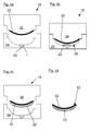
- FIG. 7 shows a trained as HinterMumvorraum foaming device with a die 24 and a male 26.
- a decor 32 and a support 33 are arranged in the article space 28 in the article space 28.
- the decor 32 is flat against the article space 28 facing side of the die 24.
- the feed nozzle 30 is arranged for the supply of the foam 22, which can be introduced in this way directly through the screen disk 1 in the article space 28.
- the carrier 33 lies flat against the object space 28 facing side of the male part 26 at.
- the carrier 33 is an already prefabricated carrier, which has an opening 40 in which the screen disc 1 connected to the feed nozzle 30 is arranged.
- a mixing chamber 4 is arranged, in which the foam 22 is formed from a first plastic component 8 and a second plastic component 10.
- the first plastic component 8 is fed to the mixing chamber 4 via a first supply line 7.
- the second plastic component 10 is supplied to the mixing chamber 4 via a second supply line 9.
- the foam 22 is now introduced through the feed nozzle 30, the screen disk 1 and arranged in the carrier 33 opening 40 in the article space 28 between the decor 32 and the carrier 33.
- the mold 18 can be opened, and the foamed composite article 12 with the cured plastic foam, so the cured foam 22 ', the decor 32 and the prefabricated carrier 33 are removed.
- FIG. 8 shows another example of a foaming device.
- a mixing head 4 comprising a feed nozzle 30 "with screen disk 1, and a pressure piston 11 are controlled by a robot 5 by means of a robot arm 6.
- the mixing head 4 is connected via a first feed line 7, with a first plastic component 8 and via a second feed line 7 Supplying the supply line 9 with a second plastic component 10.
- the two plastic components 8, 10 are fed to the mixing head 4 through the pressure piston 11 and mixed with each other in the mixing head 4 to form a foam 22.
- the foam 22 is then fed via the feed nozzle 30 "and the Screen disc 1 the article space 28 of the mold 18 is supplied. If the foam 22 is supplied to the article space 28, then The foam 22 hardens in the article space 28 and can subsequently be removed from the molding tool 18.
Priority Applications (1)
| Application Number | Priority Date | Filing Date | Title |
|---|---|---|---|
| EP15180232.9A EP3127678A1 (fr) | 2015-08-07 | 2015-08-07 | Procede et dispositif destines a faire mousser une matiere synthetique |
Applications Claiming Priority (1)
| Application Number | Priority Date | Filing Date | Title |
|---|---|---|---|
| EP15180232.9A EP3127678A1 (fr) | 2015-08-07 | 2015-08-07 | Procede et dispositif destines a faire mousser une matiere synthetique |
Publications (1)
| Publication Number | Publication Date |
|---|---|
| EP3127678A1 true EP3127678A1 (fr) | 2017-02-08 |
Family
ID=53785562
Family Applications (1)
| Application Number | Title | Priority Date | Filing Date |
|---|---|---|---|
| EP15180232.9A Pending EP3127678A1 (fr) | 2015-08-07 | 2015-08-07 | Procede et dispositif destines a faire mousser une matiere synthetique |
Country Status (1)
| Country | Link |
|---|---|
| EP (1) | EP3127678A1 (fr) |
Citations (6)
| Publication number | Priority date | Publication date | Assignee | Title |
|---|---|---|---|---|
| BE718298A (fr) * | 1967-07-19 | 1968-12-31 | ||
| JPH0425414A (ja) * | 1990-05-22 | 1992-01-29 | Tokai Chem Ind Ltd | 発泡製品の製造方法 |
| US5789457A (en) * | 1994-06-28 | 1998-08-04 | Bayer Aktiengesellschaft | Method and device for the production of foam using carbon dioxide dissolved under pressure |
| US6076246A (en) * | 1998-09-18 | 2000-06-20 | Textron Automotive Company Inc. | Method for manufacturing an automotive interior trim component and the resultant construction thereof |
| US20040217498A1 (en) * | 2003-05-02 | 2004-11-04 | Ondrus Daniel J. | Method for robotically applying large volumes of structural foam within automotive applications |
| DE10350240A1 (de) * | 2003-10-27 | 2005-05-19 | Basf Ag | Verfahren zur Einbringung von Flüssigkeiten mittels einer Fördereinrichtung in eine Form |
-
2015
- 2015-08-07 EP EP15180232.9A patent/EP3127678A1/fr active Pending
Patent Citations (6)
| Publication number | Priority date | Publication date | Assignee | Title |
|---|---|---|---|---|
| BE718298A (fr) * | 1967-07-19 | 1968-12-31 | ||
| JPH0425414A (ja) * | 1990-05-22 | 1992-01-29 | Tokai Chem Ind Ltd | 発泡製品の製造方法 |
| US5789457A (en) * | 1994-06-28 | 1998-08-04 | Bayer Aktiengesellschaft | Method and device for the production of foam using carbon dioxide dissolved under pressure |
| US6076246A (en) * | 1998-09-18 | 2000-06-20 | Textron Automotive Company Inc. | Method for manufacturing an automotive interior trim component and the resultant construction thereof |
| US20040217498A1 (en) * | 2003-05-02 | 2004-11-04 | Ondrus Daniel J. | Method for robotically applying large volumes of structural foam within automotive applications |
| DE10350240A1 (de) * | 2003-10-27 | 2005-05-19 | Basf Ag | Verfahren zur Einbringung von Flüssigkeiten mittels einer Fördereinrichtung in eine Form |
Similar Documents
| Publication | Publication Date | Title |
|---|---|---|
| EP1064135B1 (fr) | Dispositif et procede pour poser dans le moule un materiau decoratif, ainsi que pour border ce dernier d'un materiau de support | |
| DE102005037003B4 (de) | Fahrzeuginnenausstattungsteil | |
| DE102009016177A1 (de) | Verbundbauteil insbesondere für Innenraum-Verkleidungselemente von Kraftfahrzeugen und Verfahren zu dessen Herstellung | |
| DE19818881A1 (de) | Vorrichtung und Verfahren zum Formen von Innenverkleidungen für Kraftfahrzeuge | |
| DE102004041384A1 (de) | Zweistufenformen mit optionalem weichen Polster | |
| EP1886787A1 (fr) | Collage et revêtement de couches de matière première | |
| DE4337697C1 (de) | Verfahren zur Herstellung von formstabilen, kaschierten Formteilen, wie Innenverkleidungen von Kraftfahrzeugen | |
| WO2008064915A1 (fr) | Procédé de fabrication d'une pièce composite dotée d'une couche de recouvrement en plusieurs parties et pièce composite | |
| EP2525956A1 (fr) | Procédé de fabrication d'un élément de revêtement intérieur | |
| EP1767327B1 (fr) | Procédé de fabrication d'un revêtement intérieur avec une peau en deux parties et revêtement fabriqué selon ce procédé | |
| AT506942B1 (de) | Verfahren zur herstellung eines innenverkleidungsteils | |
| DE102006047355B4 (de) | Verbundteil mit einer mehrteiligen Deckschicht und Verfahren zu dessen Herstellung | |
| EP2046550B1 (fr) | Habillage présentant une couche de recouvrement en plusieurs parties et procédé pour sa fabrication | |
| EP3127678A1 (fr) | Procede et dispositif destines a faire mousser une matiere synthetique | |
| DE10218890B4 (de) | Verfahren zum Herstellen eines flächigen Verbundbauteils | |
| DE102011056759A1 (de) | Bauteil | |
| DE10110908A1 (de) | Verfahren zur Herstellung eines mehrschichtigen Verbundteils und Werkzeug | |
| DE102010037022A1 (de) | Vorrichtung und Verfahren zur Herstellung eines Formteils mit dreidimensional strukturierter Oberfläche | |
| EP2424718A1 (fr) | Dispositif de production d'une pièce moulée en matière plastique | |
| DE202008017784U1 (de) | Innenverkleidungsteil mit saugfähigem Dekormaterial | |
| EP1525081B1 (fr) | Procede de moulage par compression destine a la fabrication d'un support comportant une pellicule de moulage plastique | |
| DE19640199A1 (de) | Verfahren und Vorrichtung zur Herstellung von Kunststoffteilen mit teilkaschierter Oberfläche | |
| DE102005011474B4 (de) | Verfahren zur Herstellung von Kunststoffformteilen mit Hinterschneidungen unter Verwendung eingelegter Füllstücke | |
| DE102018118426A1 (de) | Verfahren und system zur verwendung eines offenen spritzgiessverfahrens mit einem einzelwerkzeug für verkleidungskomponenten | |
| WO2018149742A1 (fr) | Procédé de fabrication d'une unité intérieure pour un véhicule à moteur et unité intérieure pour un véhicule à moteur |
Legal Events
| Date | Code | Title | Description |
|---|---|---|---|
| PUAI | Public reference made under article 153(3) epc to a published international application that has entered the european phase |
Free format text: ORIGINAL CODE: 0009012 |
|
| STAA | Information on the status of an ep patent application or granted ep patent |
Free format text: STATUS: THE APPLICATION HAS BEEN PUBLISHED |
|
| AK | Designated contracting states |
Kind code of ref document: A1 Designated state(s): AL AT BE BG CH CY CZ DE DK EE ES FI FR GB GR HR HU IE IS IT LI LT LU LV MC MK MT NL NO PL PT RO RS SE SI SK SM TR |
|
| AX | Request for extension of the european patent |
Extension state: BA ME |
|
| STAA | Information on the status of an ep patent application or granted ep patent |
Free format text: STATUS: REQUEST FOR EXAMINATION WAS MADE |
|
| 17P | Request for examination filed |
Effective date: 20170614 |
|
| RBV | Designated contracting states (corrected) |
Designated state(s): AL AT BE BG CH CY CZ DE DK EE ES FI FR GB GR HR HU IE IS IT LI LT LU LV MC MK MT NL NO PL PT RO RS SE SI SK SM TR |
|
| STAA | Information on the status of an ep patent application or granted ep patent |
Free format text: STATUS: EXAMINATION IS IN PROGRESS |
|
| 17Q | First examination report despatched |
Effective date: 20191212 |
|
| STAA | Information on the status of an ep patent application or granted ep patent |
Free format text: STATUS: EXAMINATION IS IN PROGRESS |
|
| STAA | Information on the status of an ep patent application or granted ep patent |
Free format text: STATUS: EXAMINATION IS IN PROGRESS |
|
| P01 | Opt-out of the competence of the unified patent court (upc) registered |
Effective date: 20230427 |
|
| GRAP | Despatch of communication of intention to grant a patent |
Free format text: ORIGINAL CODE: EPIDOSNIGR1 |
|
| STAA | Information on the status of an ep patent application or granted ep patent |
Free format text: STATUS: GRANT OF PATENT IS INTENDED |
|
| INTG | Intention to grant announced |
Effective date: 20240108 |
|
| GRAS | Grant fee paid |
Free format text: ORIGINAL CODE: EPIDOSNIGR3 |
|
| GRAA | (expected) grant |
Free format text: ORIGINAL CODE: 0009210 |
|
| STAA | Information on the status of an ep patent application or granted ep patent |
Free format text: STATUS: THE PATENT HAS BEEN GRANTED |