EP3127678A1 - Device and method for plastic foaming - Google Patents
Device and method for plastic foaming Download PDFInfo
- Publication number
- EP3127678A1 EP3127678A1 EP15180232.9A EP15180232A EP3127678A1 EP 3127678 A1 EP3127678 A1 EP 3127678A1 EP 15180232 A EP15180232 A EP 15180232A EP 3127678 A1 EP3127678 A1 EP 3127678A1
- Authority
- EP
- European Patent Office
- Prior art keywords
- foam
- mold
- space
- carrier
- article
- Prior art date
- Legal status (The legal status is an assumption and is not a legal conclusion. Google has not performed a legal analysis and makes no representation as to the accuracy of the status listed.)
- Pending
Links
- 238000005187 foaming Methods 0.000 title claims abstract description 48
- 238000000034 method Methods 0.000 title claims abstract description 24
- 239000004033 plastic Substances 0.000 title description 33
- 229920003023 plastic Polymers 0.000 title description 33
- 239000006260 foam Substances 0.000 claims abstract description 109
- 239000002131 composite material Substances 0.000 claims description 14
- 229920002635 polyurethane Polymers 0.000 claims 1
- 239000004814 polyurethane Substances 0.000 claims 1
- 239000002984 plastic foam Substances 0.000 description 8
- 239000011159 matrix material Substances 0.000 description 4
- 238000005034 decoration Methods 0.000 description 3
- 239000010985 leather Substances 0.000 description 3
- 239000002649 leather substitute Substances 0.000 description 3
- 239000000463 material Substances 0.000 description 3
- 238000000465 moulding Methods 0.000 description 3
- 230000035508 accumulation Effects 0.000 description 2
- 238000009825 accumulation Methods 0.000 description 2
- 238000002347 injection Methods 0.000 description 2
- 239000007924 injection Substances 0.000 description 2
- 238000004519 manufacturing process Methods 0.000 description 2
- 238000003825 pressing Methods 0.000 description 2
- 229920005830 Polyurethane Foam Polymers 0.000 description 1
- 238000010521 absorption reaction Methods 0.000 description 1
- 239000000969 carrier Substances 0.000 description 1
- 238000006243 chemical reaction Methods 0.000 description 1
- 238000009826 distribution Methods 0.000 description 1
- 238000004049 embossing Methods 0.000 description 1
- 230000001747 exhibiting effect Effects 0.000 description 1
- 239000004744 fabric Substances 0.000 description 1
- 229920002457 flexible plastic Polymers 0.000 description 1
- 239000011888 foil Substances 0.000 description 1
- 238000001746 injection moulding Methods 0.000 description 1
- 239000002184 metal Substances 0.000 description 1
- 239000011496 polyurethane foam Substances 0.000 description 1
- 239000011148 porous material Substances 0.000 description 1
- 230000000717 retained effect Effects 0.000 description 1
- 238000009958 sewing Methods 0.000 description 1
- 239000004753 textile Substances 0.000 description 1
- 238000009423 ventilation Methods 0.000 description 1
Images


Classifications
-
- B—PERFORMING OPERATIONS; TRANSPORTING
- B29—WORKING OF PLASTICS; WORKING OF SUBSTANCES IN A PLASTIC STATE IN GENERAL
- B29C—SHAPING OR JOINING OF PLASTICS; SHAPING OF MATERIAL IN A PLASTIC STATE, NOT OTHERWISE PROVIDED FOR; AFTER-TREATMENT OF THE SHAPED PRODUCTS, e.g. REPAIRING
- B29C44/00—Shaping by internal pressure generated in the material, e.g. swelling or foaming ; Producing porous or cellular expanded plastics articles
- B29C44/34—Auxiliary operations
- B29C44/3442—Mixing, kneading or conveying the foamable material
-
- B—PERFORMING OPERATIONS; TRANSPORTING
- B29—WORKING OF PLASTICS; WORKING OF SUBSTANCES IN A PLASTIC STATE IN GENERAL
- B29C—SHAPING OR JOINING OF PLASTICS; SHAPING OF MATERIAL IN A PLASTIC STATE, NOT OTHERWISE PROVIDED FOR; AFTER-TREATMENT OF THE SHAPED PRODUCTS, e.g. REPAIRING
- B29C44/00—Shaping by internal pressure generated in the material, e.g. swelling or foaming ; Producing porous or cellular expanded plastics articles
- B29C44/02—Shaping by internal pressure generated in the material, e.g. swelling or foaming ; Producing porous or cellular expanded plastics articles for articles of definite length, i.e. discrete articles
- B29C44/12—Incorporating or moulding on preformed parts, e.g. inserts or reinforcements
- B29C44/1219—Foaming between a movable mould part and the preformed part
-
- B—PERFORMING OPERATIONS; TRANSPORTING
- B29—WORKING OF PLASTICS; WORKING OF SUBSTANCES IN A PLASTIC STATE IN GENERAL
- B29C—SHAPING OR JOINING OF PLASTICS; SHAPING OF MATERIAL IN A PLASTIC STATE, NOT OTHERWISE PROVIDED FOR; AFTER-TREATMENT OF THE SHAPED PRODUCTS, e.g. REPAIRING
- B29C44/00—Shaping by internal pressure generated in the material, e.g. swelling or foaming ; Producing porous or cellular expanded plastics articles
- B29C44/34—Auxiliary operations
- B29C44/36—Feeding the material to be shaped
- B29C44/38—Feeding the material to be shaped into a closed space, i.e. to make articles of definite length
- B29C44/383—Feeding the material to be shaped into a closed space, i.e. to make articles of definite length using spreading devices mounted in the mould, in front of the feed opening
-
- B—PERFORMING OPERATIONS; TRANSPORTING
- B29—WORKING OF PLASTICS; WORKING OF SUBSTANCES IN A PLASTIC STATE IN GENERAL
- B29K—INDEXING SCHEME ASSOCIATED WITH SUBCLASSES B29B, B29C OR B29D, RELATING TO MOULDING MATERIALS OR TO MATERIALS FOR MOULDS, REINFORCEMENTS, FILLERS OR PREFORMED PARTS, e.g. INSERTS
- B29K2075/00—Use of PU, i.e. polyureas or polyurethanes or derivatives thereof, as moulding material
Definitions
- the invention relates to a device for foaming a prefabricated injection molded part or carrier with foamable plastic or with foam according to the preamble of patent claim 1, a method for foaming a prefabricated injection molded part or carrier with foam according to the preamble of claim 9, a composite article of foamed Plastic, which has been produced by such a method according to claim 16, and a vehicle component according to claim 17.
- Moldings in the interior of vehicles, in particular of motor vehicles, such as dashboards, interior trim, door side panels, center consoles, etc. are often designed as a so-called plastic foam carrier composite.
- vehicle interior trim must meet different technical and aesthetic tasks.
- the finished vehicle interior trim parts for example, give the vehicle a higher-quality feel, or increase the sound absorption capacity of the vehicle.
- a foam usually a two-component plastic
- a foam is introduced between a mold carrier and the object to be foamed or foamed, or the foam part to be produced.
- the formed article or the foam part formed is removed again from the mold carrier.
- the plastic foam layer usually has a small thickness, which is why the plastic foam must also be very finely porous and the gas inclusions must be very small.
- Object of the present invention is therefore to provide a device for producing an article with a foam layer, in particular for producing a vehicle component, with which a particularly fine-pored and over its volume as evenly large gas inclusions exhibiting, ideally lunkerkaer, foam can be produced.
- Another object of the present invention is to provide a method for foaming, foaming and / or foaming a subject space with such a device, so that an article can be produced which has a particularly fine-pored and over its volume as uniformly large gas leaks, ideally void-free Having foam.
- a decor is to be understood as meaning a preformed film, a molded skin or a leather or synthetic leather sewing garment.
- the device according to the invention for foaming is based on the finding that optimum mixing between the plastic and the gas bubbles enclosed therein is achieved by providing a sieve at the outlet opening at which the foam emerges becomes.
- the device according to the invention for foaming, in particular for frothing and / or foaming a prefabricated carrier with foam, for example with polyurethane foam has a mold carrier which has a first half mold designed as a die, a space for receiving foam partially bounded by the die, and at least a feed nozzle for introducing the foam into the article space.
- the at least one feed nozzle has a flat sieve disk with a plurality of sieve holes, and the sieve disk is arranged in or at the at least one feed nozzle such that foam guided by the at least one feed nozzle is introduced through the sieve holes of the sieve disk into the article space of the mold carrier, wherein the Foam preferably immediately before it is introduced into the article space through which sieve holes of the sieve disk flows.
- the mold carrier may have a trained as a male second half-mold, which is alternately openable and closable against the first half-mold, so the die, wherein, when the two half-forms of the mold carrier are closed against each other, the space enclosed by the die and the male form the space and defines object space.
- the article space is in this case closed on all sides, so that, with suitable design of the male and the female, the entire surface structure and shape of the object to be formed can be provided in advance.
- a first half-mold of a mold carrier for example, a first half-tool, to be understood, which is formed recessed, so that it can accommodate, for example, an already shaped decor in its depression.
- a male part is to be understood in this document as a second half-mold of a mold carrier, for example, a second half-tool, which, for example, as a freestanding embossing dies is raised, for receiving the carrier.
- the male part can have at least one feed nozzle, which is formed as a through hole for feeding the foam through the male part into the article space.
- the die may have one or more feed nozzles formed as a bore for feeding the foam through the die into the article space.
- the channels which supply the foam space for foaming the article space to the article space are determined.
- the at least one screen disk is arranged and / or formed flat on the side of the at least one feed nozzle facing the article space.
- the inventive device has a robot arm and a mixing head connected to the robot arm, wherein the at least one feed nozzle is formed as part of the mixing head.
- a decor made of a different material is often provided with a foam layer in order to give the surface of the component the desired feel.
- the at least one decor may consist of artificial leather or leather, or at least have artificial leather or leather.
- the foam with a mixing nozzle having a mixing head which is connected to a robot, are registered in the subject space.
- the flat screen disk is advantageously formed on the side of the feed nozzle facing the article space.
- the foam can then, immediately after it has passed the flat screen disc, be entered directly into the subject space.
- an easy replacement of the flat screen disc is possible in this case, in particular if it is screwed or plugged into the feed nozzle, or only rests and is held by the carrier.
- the mixing head can have a region which has feed lines for feeding individual, for example two components of a foam, which after mixing and chemical reaction give the foam. Since foam usually cures very quickly, the mixing of the individual plastic components should take place immediately before the foam is introduced into the article space, preferably in a mixing head.
- the flat screen disc is therefore advantageously formed or arranged on the side of the space facing a foaming opening of the at least one feed nozzle.
- the at least one feed nozzle can be arranged in the die or in the male part.
- the die and / or the male are preferably movable parts of a mold forming a mold, wherein the male and female mold can be moved away from each other for opening the mold, and are movable towards each other for closing the mold.
- the mold When the mold is closed, it defines and encloses the subject space.
- a carrier is arranged on the male part, which, preferably flat, is seated on the side of the male part delimiting the article space.
- the feed nozzle can protrude into the article space so far that it can penetrate a support arranged on the side of the mold carrier at which the feed nozzle projects into the article space when the carrier has an opening for foaming through the feed nozzle.
- the inventive method for front foaming and / or foam backing a prefabricated carrier with a device of the type described has at least the following method steps:
- the prefabricated carrier is introduced into the article space.
- the foam is introduced into the article space through at least one feed nozzle and through a screen disk arranged in or at the feed nozzle and having a plurality of screen holes.
- the object space is filled up completely with the foam. After the foam has set in the article space, the composite article is formed and can be removed from the device.
- the inventive method is thus characterized by the fact that the foamable plastic or the foam is pressed through a sieve disk having a plurality of sieve holes before it is introduced into the article space.
- the sieve screen can be, for example, a grid. It can for example consist of plastic or of a metal.
- the screen disk can have a round shape, an oval shape, a quadrangular, rectangular or square shape, a polygonal shape or another planar shape.
- the sieve holes arranged in the screen disc can also be round, oval, rectangular, square or otherwise configured.
- the screen disc may also consist of a textile or other holey fabric.
- the foam is, if it was pressed immediately before through the screen disc, finer pores. Areas with large contiguous accumulations of gas can then arise in the cured product is not so easy because apparently when pressing the foam through the sieve holes of the screen plate a larger single gas volume that may have formed in the foam area, characterized in that the foam through several sieves are pressed simultaneously, are again divided into several small volumes of gas, which are spaced from each other. The gas volumes are thus reduced when pressing the foam through the sieve holes and mixed again and remain so isolated.
- the foam can be pressed for example by two or more, preferably successively arranged sieve discs with sieve holes before it is introduced into the subject space.
- the foam may be introduced into the article space by a feed nozzle formed as part of a mixing head associated with a robotic arm, wherein after filling the article space with the foam, the article space for curing the foam is closed with a second half mold.
- the second half-mold is preferably a male, to which the prefabricated carrier, preferably flat, has been applied before closing the article space.
- the mold carrier may alternatively also have a first half-mold formed as a die and a second half-mold designed as a male mold, and for forming the article space be closed between the first half-mold and the second half-mold before entering the foam.
- the mold carrier After curing of the registered foam, the mold carrier can be opened and the formed composite article, for example a vehicle component for the interior area, in particular a vehicle door inner lining or an instrument panel, be detached from the mold carrier.
- the formed composite article for example a vehicle component for the interior area, in particular a vehicle door inner lining or an instrument panel, be detached from the mold carrier.
- a decoration for example a molded skin, preferably flat, can be arranged between the matrix and the male part on the surface of the female mold facing the article space.
- the feed nozzle can protrude into the article space so far that it can penetrate a support arranged on the side of the mold carrier at which the feed nozzle projects into the article space when the carrier has a corresponding opening for foaming the article space through the feed nozzle.
- a decoration, preferably flat, on the surface of the die facing the article space is produced between the die and the male arranged, and / or a carrier, preferably flat, arranged on the object space facing surface of the male before the mold carrier is closed.
- the screen holes need not necessarily be round or oval. They may be square, rectangular, diamond-shaped or triangular, for example.
- the sieve disk can also be designed, for example, as a screen grid.
- screen discs are used which have a plurality of spaced sieve holes.
- the screen disk can also be round, rectangular or square, or, for example, have the shape of a closed polygon.
- top, bottom, left and right relate to embodiments and are not intended to be limiting in any way, even if they relate to preferred embodiments.
- FIG. 1 shows the schematic representation of a screen plate 1 with sieve holes 2.
- the screen holes 2 are round in this example, about the same size and evenly distributed over the surface of the likewise round screen disk 1.
- FIG. 2 shows a screen plate 1, which is made of a flexible plastic material.
- the sieve holes 2 of the screen disc 1 in FIG. 2 are formed substantially rectangular or square.
- the screen disk 1 is formed in this embodiment as a mesh of a plurality of individual plastic strips.
- mutually parallel first plastic strips 2a are interwoven with substantially parallel to each other arranged second plastic strip 2b, wherein the first plastic strips 2a are fused to the second plastic strip 2b and wherein the first plastic strips 2a substantially perpendicular are arranged to the second plastic strip 2b.
- a plastic braid can be produced, from which then, depending on the desired shape, the screen discs 1 can be cut or punched out.
- FIG. 3 shows a foaming device designed as a front foaming device for producing a foamed article 12, with a mold 18, which consists of two half-molds, namely a die 24 and a male 26.
- a carrier 33 At a side of the male part 26 facing an article space 28, a carrier 33 abuts flatly.
- the foaming with foam 22 takes place from the outside in that the foam 22 is pressed into the article space 28 by a foaming opening 38 ', a feed nozzle 30' arranged in a die 24, a screen disk 1 'arranged in the feed nozzle 30' and a foaming opening 36 ' becomes.
- the foamed article 12 can be removed with the hardened foam 22 'fixed to the carrier 33.
- FIGS. 4a to 4d show a method for foaming a subject space with the described front foaming device.
- FIG. 4a shows the mold carrier 18, which consists of two half-molds, namely the die 24 and the male 26, in the open state.
- a prefabricated carrier 33 is applied flat to the male part 26.
- the die 24 has the feed nozzle 30 'and the screen disk 1'.
- the two half-molds 24, 26 of the mold carrier 18 are closed against each other and the article space 28 is filled with foam 22 through the feed nozzle 30 'and the screen disk 1' to form the article space 28 like this in FIG. 4b is shown.
- the gas displaced by the foam 22 escapes from the subject space 28 by not shown ventilation holes.
- FIG. 5 shows as another example of a foaming device, a front foaming device, wherein the mold carrier 18 again has a die 24 and a male part 26.
- An article space 28 is formed in the mold carrier 18 when the mold carrier 18 is closed.
- the male part 26 has a through bore which forms a feed nozzle 30, at the end of which the article space 28 facing a screen plate 1 is arranged.
- a carrier 33 is arranged, which bears flat against the side of the male part 26 facing the article space 28.
- the screen disk 1 is arranged on the side of a foaming opening 36 facing the article space 28 of the male part 26 of the mold carrier 18.
- FIG. 6 shows a detailed view of the upper or lower part of the foaming tool, such as FIG. 5 .
- a predetermined amount of a first plastic component 8 is supplied via a first supply line 7, and a predetermined amount of a second plastic component 10 via a second supply line 9 to the mixing head 4.
- a certain amount of foam 22 which can be pressed by means of a pressure piston 11 via the feed nozzle 30 of the mixing head 4 and the screen element 1 in the article space 28.
- the mixing head 4 with the feed nozzle 30, and the pressure piston 11 is received in the male part 26.
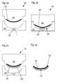
- FIG. 7 shows a trained as HinterMumvorraum foaming device with a die 24 and a male 26.
- a decor 32 and a support 33 are arranged in the article space 28 in the article space 28.
- the decor 32 is flat against the article space 28 facing side of the die 24.
- the feed nozzle 30 is arranged for the supply of the foam 22, which can be introduced in this way directly through the screen disk 1 in the article space 28.
- the carrier 33 lies flat against the object space 28 facing side of the male part 26 at.
- the carrier 33 is an already prefabricated carrier, which has an opening 40 in which the screen disc 1 connected to the feed nozzle 30 is arranged.
- a mixing chamber 4 is arranged, in which the foam 22 is formed from a first plastic component 8 and a second plastic component 10.
- the first plastic component 8 is fed to the mixing chamber 4 via a first supply line 7.
- the second plastic component 10 is supplied to the mixing chamber 4 via a second supply line 9.
- the foam 22 is now introduced through the feed nozzle 30, the screen disk 1 and arranged in the carrier 33 opening 40 in the article space 28 between the decor 32 and the carrier 33.
- the mold 18 can be opened, and the foamed composite article 12 with the cured plastic foam, so the cured foam 22 ', the decor 32 and the prefabricated carrier 33 are removed.
- FIG. 8 shows another example of a foaming device.
- a mixing head 4 comprising a feed nozzle 30 "with screen disk 1, and a pressure piston 11 are controlled by a robot 5 by means of a robot arm 6.
- the mixing head 4 is connected via a first feed line 7, with a first plastic component 8 and via a second feed line 7 Supplying the supply line 9 with a second plastic component 10.
- the two plastic components 8, 10 are fed to the mixing head 4 through the pressure piston 11 and mixed with each other in the mixing head 4 to form a foam 22.
- the foam 22 is then fed via the feed nozzle 30 "and the Screen disc 1 the article space 28 of the mold 18 is supplied. If the foam 22 is supplied to the article space 28, then The foam 22 hardens in the article space 28 and can subsequently be removed from the molding tool 18.
Abstract
Es wird ein Verfahren zum Hinter- oder Frontschäumeneines Gegenstandes, insbesondere eines Fahrzeugbauteils mit einem Schaum (22') beschrieben, bei welchen der Schaum (22') durch eine mehrere Sieblöcher (2) aufweisende, flächige Siebscheibe (1) gepresst wird.The invention relates to a process for the rear or front foaming of an article, in particular of a vehicle component with a foam (22 '), in which the foam (22') is pressed through a flat screen disk (1) having a plurality of screen holes (2).
Description
Die Erfindung betrifft eine Vorrichtung zum Beschäumen eines vorgefertigten Spritzgußteils bzw. Trägers mit schäumbarem Kunststoff bzw. mit Schaum nach dem Oberbegriff des Patentanspruchs 1, ein Verfahren zum Beschäumen eines vorgefertigten Spritzgußteils bzw. Trägers mit Schaum nach dem Oberbegriff des Patentanspruchs 9, einen Verbundgegenstand aus geschäumtem Kunststoff, der mit einem solchen Verfahren hergestellt worden ist nach Patentanspruch 16, sowie ein Fahrzeugbauteil nach Patentanspruch 17.The invention relates to a device for foaming a prefabricated injection molded part or carrier with foamable plastic or with foam according to the preamble of
Formteile im Innenraum von Fahrzeugen, insbesondere von Kraftfahrzeugen, wie beispielsweise Armaturentafeln, Innenverkleidungen, Türseitenverkleidungen, Mittelkonsolen usw. sind häufig als ein sogenannter Kunststoffschaum-Träger-Verbund ausgebildet. Solche Fahrzeuginnenverkleidungen müssen unterschiedlichen technischen und ästhetischen Aufgaben gerecht werden. Die fertiggestellten Fahrzeuginnenraumverkleidungsteile sollen beispielsweise dem Fahrzeug eine höherwertige Haptik geben, oder das Schallabsorptionsvermögen des Fahrzeugs erhöhen.Moldings in the interior of vehicles, in particular of motor vehicles, such as dashboards, interior trim, door side panels, center consoles, etc. are often designed as a so-called plastic foam carrier composite. Such vehicle interior trim must meet different technical and aesthetic tasks. The finished vehicle interior trim parts, for example, give the vehicle a higher-quality feel, or increase the sound absorption capacity of the vehicle.
Bei der Herstellung derartiger Formteile wird ein Schaum, in der Regel ein Zweikomponentenkunststoff zwischen einem Formträger und dem zu beschäumenden oder auszuschäumenden Gegenstand, oder dem herzustellenden Schaumteil eingetragen. Nach dem Aushärten des Kunststoffschaumes wird der gebildete Gegenstand oder das gebildete Schaumteil wieder vom Formträger abgelöst. Die Kunststoffschaumschicht hat meist eine geringe Dicke, weshalb der Kunststoffschaum auch sehr feinporig sein muss und die Gaseinschlüsse sehr klein sein müssen.In the production of such moldings, a foam, usually a two-component plastic, is introduced between a mold carrier and the object to be foamed or foamed, or the foam part to be produced. After curing of the plastic foam, the formed article or the foam part formed is removed again from the mold carrier. The plastic foam layer usually has a small thickness, which is why the plastic foam must also be very finely porous and the gas inclusions must be very small.
Beim Schäumen kann es jedoch passieren, dass die anfangs etwa gleich großen Gaseinschlüsse, die sich in dem Kunststoffschaum bilden, während des Schäumvorgangs oder unmittelbar nach dem Schäumvorgang sich lokal zu größeren Gaseinschlüssen verbinden, so dass der ausgehärtete Kunststoff keine gleichmäßige Form, Elastizität und Härte mehr aufweist. Auch können sich beim Schäumen einzelne größere Gaseinschlüsse und Gasansammlungen bilden, die beim Aushärten des Schaums lokal einfrieren.During foaming, however, it may happen that the initially approximately equal gas inclusions that form in the plastic foam, connect locally during the foaming process or immediately after the foaming process to larger gas inclusions, so that the cured plastic no uniform shape, elasticity and hardness more having. Also, during foaming, individual larger gas inclusions and gas accumulations can form, which locally freeze when the foam hardens.
Aufgabe der vorliegenden Erfindung ist es daher, eine Vorrichtung zum Herstellen eines Gegenstandes mit einer Schaumschicht, insbesondere zum Herstellen eines Fahrzeugbauteils bereitzustellen, mit welcher ein besonders feinporiger und über sein Volumen möglichst gleichmäßig große Gaseinschlüsse aufweisender, idealerweise lunkerfreier, Schaum hergestellt werden kann. Weitere Aufgabe der vorliegenden Erfindung ist es, ein Verfahren zum Beschäumen, Schäumen und/oder Ausschäumen eines Gegenstandsraumes mit solch einer Vorrichtung bereitzustellen, so daß ein Gegenstand hergestellt werden kann, der einen besonders feinporigen und über seinem Volumen möglichst gleichmäßig große Gasschlüsse aufweisenden, idealerweise lunkerfreien, Schaum aufweist. Schließlich ist es Aufgabe der Erfindung, einen solchen Gegenstand, beispielsweise ein Schaumteil, das z. B. mit einem Dekor und/oder einem Träger verbunden ist, mit hinreichend homogener Schaumporigkeit und - härte, bereitzustellen. Unter einem Dekor soll vorliegend eine vorgeformte Folie, eine Formhaut oder ein Leder- oder Kunstledernähkleid verstanden werden.Object of the present invention is therefore to provide a device for producing an article with a foam layer, in particular for producing a vehicle component, with which a particularly fine-pored and over its volume as evenly large gas inclusions exhibiting, ideally lunkerfreier, foam can be produced. Another object of the present invention is to provide a method for foaming, foaming and / or foaming a subject space with such a device, so that an article can be produced which has a particularly fine-pored and over its volume as uniformly large gas leaks, ideally void-free Having foam. Finally, it is an object of the invention to provide such an article, for example a foam part, the z. B. with a decor and / or a carrier, with sufficiently homogeneous foam porosity and - hardness to provide. In the present case, a decor is to be understood as meaning a preformed film, a molded skin or a leather or synthetic leather sewing garment.
Diese Aufgabe wird gelöst durch eine Vorrichtung nach Anspruch 1, ein Verfahren nach Anspruch 9, einem Verbundgegenstand aus Schaum nach Anspruch 16 sowie einem Fahrzeugbauteil nach Anspruch 17. Vorteilhafte Ausführungsformen sind in den jeweiligen Unteransprüchen offenbart.This object is achieved by a device according to
Die erfindungsgemäße Vorrichtung zum Beschäumen, insbesondere zum Frontschäumen und/oder Hinterschäumen eines vorgefertigten Trägers mit Schaum beruht auf der Erkenntnis, dass durch Vorsehen eines Siebs an der Austrittsöffnung, an der der Schaum austritt, eine optimale Durchmischung zwischen dem Kunststoff und den darin eingeschlossenen Gasbläschen erreicht wird.The device according to the invention for foaming, in particular for front foaming and / or foam backing of a prefabricated carrier with foam, is based on the finding that optimum mixing between the plastic and the gas bubbles enclosed therein is achieved by providing a sieve at the outlet opening at which the foam emerges becomes.
Die erfindungsgemäße Vorrichtung zum Beschäumen, insbesondere zum frontschäumen und/oder Hinterschäumen eines vorgefertigten Trägers mit Schaum, beispielsweise mit Polyurethanschaum, weist einen Formträger auf, der eine als Matrize ausgebildete erste Halbform, einen von der Matrize teilweise begrenzten Gegenstandsraum zur Aufnahme von Schaum, sowie wenigstens eine Zuführdüse zum Eintragen des Schaums in den Gegenstandsraum aufweist. Die wenigstens eine Zuführdüse weist eine flächige Siebscheibe mit mehreren Sieblöchern auf, und die Siebscheibe ist in oder an der wenigstens einen Zuführdüse so angeordnet, dass durch die wenigstens eine Zuführdüse geleiteter Schaum durch die Sieblöcher der Siebscheibe in den Gegenstandsraum des Formträgers eingetragen wird, wobei der Schaum vorzugsweise unmittelbar bevor er in den Gegenstandsraum eingetragen wird, durch die Sieblöcher der Siebscheibe hindurchfließt.The device according to the invention for foaming, in particular for frothing and / or foaming a prefabricated carrier with foam, for example with polyurethane foam, has a mold carrier which has a first half mold designed as a die, a space for receiving foam partially bounded by the die, and at least a feed nozzle for introducing the foam into the article space. The at least one feed nozzle has a flat sieve disk with a plurality of sieve holes, and the sieve disk is arranged in or at the at least one feed nozzle such that foam guided by the at least one feed nozzle is introduced through the sieve holes of the sieve disk into the article space of the mold carrier, wherein the Foam preferably immediately before it is introduced into the article space through which sieve holes of the sieve disk flows.
Mit einer solchen Vorrichtung kann in dem Gegenstandsraum ein besonders gleichmäßiger und homogener Kunststoffschaum ausgebildet werden.With such a device, a particularly uniform and homogeneous plastic foam can be formed in the article space.
Dabei kann der Formträger eine als Patrize ausgebildete zweite Halbform aufweisen, die wechselweise gegen die erste Halbform, also die Matrize öffen- und schließbar ist, wobei, wenn die beiden Halbformen des Formträgers gegeneinander geschlossen sind, der von der Matrize und von der Patrize umschlossene Raum den Gegenstandsraum bildet und definiert.In this case, the mold carrier may have a trained as a male second half-mold, which is alternately openable and closable against the first half-mold, so the die, wherein, when the two half-forms of the mold carrier are closed against each other, the space enclosed by the die and the male form the space and defines object space.
Der Gegenstandsraum ist in diesem Fall zu allen Seiten hin abgeschlossen, so dass, bei geeigneter Ausführung der Patrize und der Matrize die gesamte Oberflächenstruktur und -form des zu bildenden Gegenstands vorab vorgesehen werden kann.The article space is in this case closed on all sides, so that, with suitable design of the male and the female, the entire surface structure and shape of the object to be formed can be provided in advance.
Unter einer Matrize soll in dieser Schrift eine erste Halbform eines Formträgers, beispielsweise ein erstes Halbwerkzeug, verstanden werden, welches vertieft ausgebildet ist, so dass es beispielsweise ein bereits geformtes Dekor in seiner Vertiefung aufnehmen kann.Under a die in this document, a first half-mold of a mold carrier, for example, a first half-tool, to be understood, which is formed recessed, so that it can accommodate, for example, an already shaped decor in its depression.
Unter einer Patrize soll in dieser Schrift eine zweite Halbform eines Formträgers verstanden werden, beispielsweise ein zweites Halbwerkzeug, welches, beispielsweise wie ein freistehender Prägestempel erhaben ausgebildet ist, zur Aufnahme des Trägers.A male part is to be understood in this document as a second half-mold of a mold carrier, for example, a second half-tool, which, for example, as a freestanding embossing dies is raised, for receiving the carrier.
Die Patrize kann wenigstens eine Zuführdüse aufweisen, welche als Durchbohrung zum Zuführen des Schaums durch die Patrize in den Gegenstandsraum ausgebildet ist.The male part can have at least one feed nozzle, which is formed as a through hole for feeding the foam through the male part into the article space.
Alternativ oder zusätzlich kann die Matrize eine oder mehrere Zuführdüsen aufweisen, die als Durchbohrung zum Zuführen des Schaums durch die Matrize in den Gegenstandsraum ausgebildet sind. Dadurch werden die Kanäle, die dem Gegenstandsraum den Schaum zum Ausschäumen des Gegenstandsraums zuführen, bestimmt.Alternatively or additionally, the die may have one or more feed nozzles formed as a bore for feeding the foam through the die into the article space. As a result, the channels which supply the foam space for foaming the article space to the article space are determined.
In einer vorteilhaften Ausführungsform ist die wenigstens eine Siebscheibe flächig an der dem Gegenstandsraum zugewandte Seite der wenigstens einen Zuführdüse angeordnet und / oder ausgebildet.In an advantageous embodiment, the at least one screen disk is arranged and / or formed flat on the side of the at least one feed nozzle facing the article space.
In einer möglichen Ausführung weist die erfinderische Vorrichtung einen Roboterarm und einen mit dem Roboterarm verbundenen Mischkopf auf, wobei die wenigstens eine Zuführdüse als Teil des Mischkopfes ausgebildet ist.In one possible embodiment, the inventive device has a robot arm and a mixing head connected to the robot arm, wherein the at least one feed nozzle is formed as part of the mixing head.
Bei der Herstellung von Interieur-Bauteilen für die Autoindustrie wird häufig ein Dekor aus einem anderen Material mit einer Schaumschicht versehen, um der Oberfläche des Bauteils dadurch die gewünschte Haptik zu verleihen.In the manufacture of interior components for the automotive industry, a decor made of a different material is often provided with a foam layer in order to give the surface of the component the desired feel.
Um eine besonders hochwertige Oberfläche zu bilden, kann das wenigstens ein Dekor aus Kunstleder oder Leder bestehen, oder zumindest Kunstleder oder Leder aufweisen.In order to form a particularly high-quality surface, the at least one decor may consist of artificial leather or leather, or at least have artificial leather or leather.
In einer Ausgestaltung der Erfindung kann der Schaum mit einem eine Zuführdüse aufweisenden Mischkopf, welcher mit einem Roboter verbunden ist, in den Gegenstandsraum eingetragen werden.In one embodiment of the invention, the foam with a mixing nozzle having a mixing head, which is connected to a robot, are registered in the subject space.
Die flächige Siebscheibe ist vorteilhafterweise an der dem Gegenstandsraum zugewandten Seite der Zuführdüse ausgebildet. Der Schaum kann dann, unmittelbar nachdem er die flächige Siebscheibe passiert hat, direkt in den Gegenstandsraum eingetragen werden. Darüber hinaus ist in diesem Fall ein leichter Austausch der flächigen Siebscheibe möglich, insbesondere dann, wenn sie an die Zuführdüse angeschraubt oder angesteckt ist, oder nur anliegt und vom Träger gehalten wird.The flat screen disk is advantageously formed on the side of the feed nozzle facing the article space. The foam can then, immediately after it has passed the flat screen disc, be entered directly into the subject space. In addition, an easy replacement of the flat screen disc is possible in this case, in particular if it is screwed or plugged into the feed nozzle, or only rests and is held by the carrier.
Der Mischkopf kann einen Bereich aufweisen, welcher Zuleitungen zum Zuführen einzelner, beispielsweise zweier Komponenten eines Schaums aufweist, die nach Vermischen und chemischer Reaktion den Schaum ergeben. Da Schaum in der Regel sehr schnell aushärtet, sollte das Mischen der einzelnen Kunststoffkomponenten unmittelbar vor dem Eintragen des Schaums in den Gegenstandsraum, vorzugsweise in einem Mischkopf, erfolgen. Die flächige Siebscheibe ist daher vorteilhafterweise an der dem Gegenstandsraum zugewandten Seite einer Beschäumöffnung der wenigstens einen Zuführdüse ausgebildet oder angeordnet.The mixing head can have a region which has feed lines for feeding individual, for example two components of a foam, which after mixing and chemical reaction give the foam. Since foam usually cures very quickly, the mixing of the individual plastic components should take place immediately before the foam is introduced into the article space, preferably in a mixing head. The flat screen disc is therefore advantageously formed or arranged on the side of the space facing a foaming opening of the at least one feed nozzle.
Je nach gewünschter Beschäumung kann die wenigstens eine Zuführdüse in der Matrize oder in der Patrize angeordnet sein.Depending on the desired foaming, the at least one feed nozzle can be arranged in the die or in the male part.
Die Matrize und/oder die Patrize sind vorzugsweise bewegliche Teile eines eine Form bildenden Formwerkzeugs, wobei Patrize und Matrize zum Öffnen des Formwerkzeugs voneinander wegbewegt werden können, und zum Schließen des Formwerkzeugs aufeinander zu bewegbar sind. Wenn das Formwerkzeug geschlossen ist, definiert und umschließt es den Gegenstandsraum.The die and / or the male are preferably movable parts of a mold forming a mold, wherein the male and female mold can be moved away from each other for opening the mold, and are movable towards each other for closing the mold. When the mold is closed, it defines and encloses the subject space.
In der erfinderischen Vorrichtung ist an der Patrize ein Träger angeordnet, der, vorzugsweise flächig, auf der den Gegenstandsraum begrenzenden Seite der Patrize aufsitzt.In the inventive device, a carrier is arranged on the male part, which, preferably flat, is seated on the side of the male part delimiting the article space.
Die Zuführdüse kann soweit in den Gegenstandsraum hineinragen, daß sie einen an der Seite des Formträgers, an welcher die Zuführdüse in den Gegenstandsraum hineinragt, angeordneten Träger durchdringen kann, wenn der Träger eine Öffnung zum Beschäumen durch die Zuführdüse aufweist.The feed nozzle can protrude into the article space so far that it can penetrate a support arranged on the side of the mold carrier at which the feed nozzle projects into the article space when the carrier has an opening for foaming through the feed nozzle.
Das erfinderische Verfahren zum Frontschäumen und/oder Hinterschäumen eines vorgefertigten Trägers mit einer Vorrichtung der beschriebenen Art, weist zumindest folgende Verfahrensschritte auf:The inventive method for front foaming and / or foam backing a prefabricated carrier with a device of the type described, has at least the following method steps:
Zunächst wird der vorgefertigte Träger in den Gegenstandsraum eingebracht. Dann wird der Schaum durch wenigstens eine Zuführdüse und durch eine in oder an der Zuführdüse angeordnete, mehrere Sieblöcher aufweisende Siebscheibe in den Gegenstandsraum eingetragen. Der Gegenstandsraum wird dabei mit dem Schaum vollständig aufgefüllt. Nach dem Aushärten lassen des Schaums in dem Gegenstandsraum ist der Verbundgegenstand gebildet und kann der Vorrichtung entnommen werden.First, the prefabricated carrier is introduced into the article space. Then the foam is introduced into the article space through at least one feed nozzle and through a screen disk arranged in or at the feed nozzle and having a plurality of screen holes. The object space is filled up completely with the foam. After the foam has set in the article space, the composite article is formed and can be removed from the device.
Das erfinderische Verfahren zeichnet sich somit dadurch aus, dass der schäumbare Kunststoff bzw. der Schaum durch eine mehrere Sieblöcher aufweisende Siebscheibe gepresst wird, bevor er in den Gegenstandsraum eingetragen wird. Die Siebscheibe kann dabei beispielsweise ein Rastergitter sein. Sie kann beispielsweise aus Kunststoff bestehen oder auch aus einem Metall. Die Siebscheibe, kann eine runde Form, eine ovale Form, eine viereckige, rechteckige oder quadratische Form, eine Polygonform oder eine sonstige flächige Form aufweisen. Die in der Siebscheibe angeordneten Sieblöcher können ebenfalls rund, oval, rechteckig, quadratisch oder anderweitig ausgestaltet sein. Die Siebscheibe kann auch aus einem Textil- oder aus einem sonstigen löchrigen Gewebe bestehen.The inventive method is thus characterized by the fact that the foamable plastic or the foam is pressed through a sieve disk having a plurality of sieve holes before it is introduced into the article space. The sieve screen can be, for example, a grid. It can for example consist of plastic or of a metal. The screen disk can have a round shape, an oval shape, a quadrangular, rectangular or square shape, a polygonal shape or another planar shape. The sieve holes arranged in the screen disc can also be round, oval, rectangular, square or otherwise configured. The screen disc may also consist of a textile or other holey fabric.
Der Schaum wird, wenn er unmittelbar vorher durch die Siebscheibe gepresst wurde, feinporiger. Bereiche mit großen zusammenhängenden Gasansammlungen können im ausgehärteten Produkt dann nicht so leicht entstehen, da offenbar beim Durchpressen des Schaums durch die Sieblöcher der Siebscheibe ein größeres einzelnes Gasvolumen, das sich möglicherweise im Schaumbereich gebildet hat, dadurch, dass der Schaum durch mehrere Sieblöcher gleichzeitig gepresst wird, wieder in mehrere kleine Gasvolumina aufgeteilt werden, die voneinander beabstandet sind. Die Gasvolumina werden somit beim Durchpressen des Schaums durch die Sieblöcher verkleinert und wieder neu vermischt und bleiben so vereinzelt. Auf diese Weise kann ein hinreichend feinporiger Schaum erzeugt werden, dessen sehr kleine Gaseinschlüsse so langsam durch das Material wandern, daß der Kunststoff ausgehärtet ist, bevor sie sich wieder zu größeren Gaseinschlüssen vereinigen können, wodurch eine Vereinigung mehrerer Gaseinschlüsse zu einem größeren Gaseinschluss verhindert wird. Da der Schaum relativ schnell aushärtet, wird die Bewegung der Gaseinschlüsse zeitig beendet.The foam is, if it was pressed immediately before through the screen disc, finer pores. Areas with large contiguous accumulations of gas can then arise in the cured product is not so easy because apparently when pressing the foam through the sieve holes of the screen plate a larger single gas volume that may have formed in the foam area, characterized in that the foam through several sieves are pressed simultaneously, are again divided into several small volumes of gas, which are spaced from each other. The gas volumes are thus reduced when pressing the foam through the sieve holes and mixed again and remain so isolated. In this way, a sufficiently fine-pored foam can be generated, the very small gas bubbles migrate so slowly through the material that the plastic is cured before they can reunite to larger gas inclusions, thereby preventing a combination of multiple gas inclusions to a larger gas inclusion. Since the foam hardens relatively quickly, the movement of the gas inclusions is terminated early.
Um eine noch feinporigere Kunststoffgasverteilung zu erzeugen, kann der Schaum beispielsweise auch durch zwei oder mehrere, vorzugsweise hintereinander angeordnete Siebscheiben mit Sieblöchern gepresst werden, bevor er in den Gegenstandsraum eingetragen wird.In order to produce a still finer-pored plastic gas distribution, the foam can be pressed for example by two or more, preferably successively arranged sieve discs with sieve holes before it is introduced into the subject space.
Der Schaum kann durch eine als Teil eines mit einem Roboterarm verbundenen Mischkopfes ausgebildete Zuführdüse in den Gegenstandsraum eingetragen werden, wobei nach dem Auffüllen des Gegenstandsraums mit dem Schaum der Gegenstandsraum zum Aushärten lassen des Schaums mit einer zweiten Halbform geschlossen wird. Die zweite Halbform ist dabei vorzugsweise eine Patrize, an welcher der vorgefertigte Träger, vorzugsweise flächig, vor dem Schließen des Gegenstandsraums angelegt worden ist.The foam may be introduced into the article space by a feed nozzle formed as part of a mixing head associated with a robotic arm, wherein after filling the article space with the foam, the article space for curing the foam is closed with a second half mold. The second half-mold is preferably a male, to which the prefabricated carrier, preferably flat, has been applied before closing the article space.
Der Formträger kann alternativ auch eine als Matrize ausgebildete erste Halbform, sowie eine als Patrize ausgebildete zweite Halbform aufweisen, und zum Bilden des Gegenstandsraums zwischen der ersten Halbform und der zweiten Halbform vor dem Eintragen des Schaums geschlossen werden.The mold carrier may alternatively also have a first half-mold formed as a die and a second half-mold designed as a male mold, and for forming the article space be closed between the first half-mold and the second half-mold before entering the foam.
Nach dem Aushärten des eingetragenen Schaums kann der Formträger geöffnet und der gebildete Verbundgegenstand, beispielsweise ein Fahrzeugbauteil für den Interieur-Bereich, insbesondere eine Fahrzeugtürinnenverkleidung oder eine Instrumententafel von dem Formträger abgelöst werden.After curing of the registered foam, the mold carrier can be opened and the formed composite article, for example a vehicle component for the interior area, in particular a vehicle door inner lining or an instrument panel, be detached from the mold carrier.
Vor dem Schließen des Formträgers kann zwischen der Matrize und der Patrize ein Dekor, beispielsweise eine Formhaut, vorzugsweise flächig, auf der dem Gegenstandsraum zugewandten Oberfläche der Matrize angeordnet werden.Before the mold carrier is closed, a decoration, for example a molded skin, preferably flat, can be arranged between the matrix and the male part on the surface of the female mold facing the article space.
Der Träger kann vor dem Schließen des Formträgers zwischen der Matrize und der Patrize, vorzugsweise flächig, auf der dem Gegenstandsraum zugewandten Oberfläche der Patrize angelegt werden.Before closing the mold carrier, the carrier may be applied between the die and the male part, preferably flat, on the surface of the male part facing the article space.
Die Zuführdüse kann soweit in den Gegenstandsraum hineinragen, dass sie einen an der Seite des Formträgers, an welcher die Zuführdüse in den Gegenstandsraum hineinragt, angeordneten Träger durchdringen kann, wenn der Träger eine entsprechende Öffnung zum Beschäumen des Gegenstandsraums durch die Zuführdüse aufweist.The feed nozzle can protrude into the article space so far that it can penetrate a support arranged on the side of the mold carrier at which the feed nozzle projects into the article space when the carrier has a corresponding opening for foaming the article space through the feed nozzle.
Der Schaum kann dann beispielsweise durch diese Öffnung in dem Träger in den Gegenstandsraum eingetragen werden. In diesem Fall wird der Träger frontgeschäumt.The foam can then be introduced, for example, through this opening in the carrier in the article space. In this case, the carrier is front-foamed.
In bevorzugten Ausführungsformen des Verfahrens wird zwischen der Matrize und der Patrize ein Dekor, vorzugsweise flächig, auf der dem Gegenstandsraum zugewandten Oberfläche der Matrize angeordnet, und/oder ein Träger, vorzugsweise flächig, auf der dem Gegenstandsraum zugewandten Oberfläche der Patrize angeordnet, bevor der Formträger geschlossen wird. Auf diese Weise ist es möglich, geschäumte Verbundstoffgegenstände herzustellen, die auf der einen Seite die gewünschte Haptik aufweisen, auf der anderen Seite jedoch als formstabile Elemente und Teile von beispielsweise Fahrzeugen verwendet werden können.In preferred embodiments of the method, a decoration, preferably flat, on the surface of the die facing the article space is produced between the die and the male arranged, and / or a carrier, preferably flat, arranged on the object space facing surface of the male before the mold carrier is closed. In this way it is possible to produce foamed composite articles which on the one hand have the desired feel, but on the other hand can be used as dimensionally stable elements and parts of, for example, vehicles.
Zur Bildung einer Siebscheibe müssen die Sieblöcher nicht notwendigerweise rund oder oval sein. Sie können beispielsweise quadratisch, rechteckig, rautenförmig oder dreieckig ausgebildet sein. Die Siebscheibe kann beispielsweise auch als Rastergitter ausgebildet sein.To form a screen disc, the screen holes need not necessarily be round or oval. They may be square, rectangular, diamond-shaped or triangular, for example. The sieve disk can also be designed, for example, as a screen grid.
Für die Hinterschäumung/Frontschäumung von Formhäuten oder Trägern werden vorzugsweise Siebscheiben eingesetzt, die mehrere voneinander beabstandete Sieblöcher aufweisen. Die Siebscheibe kann auch rund, rechteckig oder quadratisch ausgebildet sein, oder beispielsweise die Form eines geschlossenen Polygons aufweisen.For the foam backing / front foam of molded skins or straps preferably screen discs are used which have a plurality of spaced sieve holes. The screen disk can also be round, rectangular or square, or, for example, have the shape of a closed polygon.
Die in der nachfolgenden Beschreibung verwendeten Bezeichnungen wie oben, unten, links und rechts beziehen sich auf Ausführungsbeispiele und sollen in keiner Weise einschränkend sein, auch dann nicht, wenn sie sich auf bevorzugte Ausführungsformen beziehen.The terms used in the following description such as top, bottom, left and right relate to embodiments and are not intended to be limiting in any way, even if they relate to preferred embodiments.
Die Erfindung wird nachfolgend anhand von Zeichnungen näher erläutert. Es zeigen:
- Figur 1:
- ein erstes Beispiel einer Siebscheibe,
- Figur 2:
- ein zweites Beispiel einer Siebscheibe,
- Figur 3:
- eine als Frontschäumvorrichtung ausgebildete Beschäumvorrichtung,
- Figur 4:
- ein Verfahren zum Schäumen eines Gegenstandsraumes mit der Frontschäumvorrichtung von
Figur 3 , - Figur 5:
- ein Formwerkzeug mit eingelegtem Träger zur Frontbeschäumung,
- Figur 6:
- eine Werkzeughälfte mit Mischkopf,
- Figur 7:
- ein Formwerkzeug mit eingelegtem Träger und Dekor zur Hinterschäumung,
- Figur 8:
- eine Matrize mit eingelegtem Dekor und einen Roboter.
- FIG. 1:
- a first example of a screen disc,
- FIG. 2:
- a second example of a screen disc,
- FIG. 3:
- a foaming device designed as a front foaming device,
- FIG. 4:
- a method for foaming a subject space with the front foaming device of
FIG. 3 . - FIG. 5:
- a mold with an inserted carrier for front foaming,
- FIG. 6:
- a tool half with mixing head,
- FIG. 7:
- a mold with inlaid support and decoration for foam backing,
- FIG. 8:
- a matrix with inlaid decor and a robot.
Die
Durch eine Beschäumöffnung 38 kann, wenn der Formträger 18 geschlossen und der Gegenstandsraum 28 zwischen der Patrize 26 und der Matrize 24 ausgebildet ist, ein Schaum 22 durch die Zuführdüse 30 und die Siebscheibe 1, sowie durch eine Öffnung 40 des Trägers 33, in den Gegenstandsraum 28 eingeleitet werden, um den Träger 33 frontzubeschäumen. Da der Schaum 22 durch die Siebscheibe 1 geleitet wird, bevor er in den Gegenstandsraum 28 eindringt, entsteht ein homogener, gleichmäßiger und lunkerfreier Schaum. Der Schaum 22 verbindet sich in dem Gegenstandsraum 28 mit dem Träger 33 und härtet in dem Gegenstandsraum 28 aus. Nachdem der Schaum 22 ausgehärtet ist, kann die Form 18, bzw. der Formträger 18 geöffnet und der Verbundgegenstand 12 mit dem ausgehärteten Schaum 22' und dem Träger 33 entnommen werden. Selbstverständlich kann auch in diesem Ausführungsbeispiel ein mehrkomponentiger Kunststoffschaum verwendet werden, dessen einzelne Komponenten in einem oberhalb der Beschäumöffnung 38 der Patrize angeordneten Mischkopf 4 miteinander vermischt werden.By means of a foaming
Der Schaum 22 wird nun durch die Zuführdüse 30, die Siebscheibe 1 und die in dem Träger 33 angeordnete Öffnung 40 in den Gegenstandsraum 28 zwischen dem Dekor 32 und dem Träger 33 eingeleitet. Nachdem der Schaum 22 ausgehärtet ist, kann die Form 18 geöffnet, und der geschäumte Verbundgegenstand 12 mit dem ausgehärteten Kunststoffschaum, also dem ausgehärteten Schaum 22', dem Dekor 32 und dem vorgefertigten Träger 33 entnommen werden.The
Die Erfindung wurde anhand bevorzugter Ausführungsbeispiele erläutert ohne auf diese Ausführungsbeispiele weiter beschränkt zu sein. So kann beispielsweise der Mischkopf 4 in die Matrize oder Patrize, beispielsweise formschlüssig, integriert sein. Der zugeführte Kunststoff kann einkomponentig, zweikomponentig oder auch mehrkomponentig sein. Selbstverständlich können auch die Formen und/oder Formträger, die Matrizen und/oder die Patrizen Entlüftungsbohrungen aufweisen, die dazu dienen, das durch den Schaum verdrängte Gas aus dem Gegenstandsraum auszuleiten. Die Merkmale der einzelnen Ausführungsbeispiele sind somit frei mit funktionell gleichwirkenden Merkmalen anderer Ausführungsbeispiele kombinierbar oder beliebig austauschbar, sofern der Erfindungsgedanke dabei erhalten bleibt.The invention has been explained with reference to preferred embodiments without being further limited to these embodiments. Thus, for example, the mixing
- 11
- Siebscheibe (Patrize)Screen disc (male)
- 1'1'
- Siebscheibe (Matrize)Screen disc (matrix)
- 22
- Sieblöcherscreen holes
- 2a2a
- Erste KunststoffstreifenFirst plastic strips
- 2b2 B
- Zweite KunststoffstreifenSecond plastic strips
- 44
- Mischkopfmixing head
- 55
- Roboterrobot
- 66
- Roboterarmrobot arm
- 77
- Erste ZuleitungFirst supply line
- 88th
- Erste KunststoffkomponenteFirst plastic component
- 99
- Zweite ZuleitungSecond supply line
- 1010
- Zweite KunststoffkomponenteSecond plastic component
- 1111
- Druckkolbenpressure piston
- 1212
- Gegenstand, Verbundgegenstand, SchaumteilArticle, composite article, foam part
- 1818
- Formträger, Formwerkzeug, SchaumwerkzeugMold carrier, mold, foam tool
- 2222
- Schaumfoam
- 22'22 '
- ausgehärteter Schaumcured foam
- 2424
- Matrize, erste HalbformMatrix, first half form
- 2626
- Patrize, zweite HalbformPatrize, second half form
- 2828
- GegenstandsraumObject space
- 3030
- Zuführdüse, PatrizeFeed nozzle, male
- 30'30 '
- Zuführdüse, MatrizeFeed nozzle, die
- 30"30 "
- Zuführdüse, MischkopfFeed nozzle, mixing head
- 3232
- Formhaut, Dekor, Haut, FolieForm skin, decor, skin, foil
- 3333
- Trägercarrier
- 3636
- Beschäumöffnung, PatrizeFoam opening, male
- 36'36 '
- Beschäumöffnung, MatrizeFoam opening, die
- 3838
- Beschäumöffnung, PatrizeFoam opening, male
- 38'38 '
- Beschäumöffnung, MatrizeFoam opening, die
- 4040
- Öffnung, SpritzgußteilOpening, injection molding
Claims (17)
dadurch gekennzeichnet, dass der Formträger (18) eine als Patrize (26) ausgebildete zweite Halbform aufweist, die wechselweise gegen die Matrize (24) öffen- und schließbar ist, wobei, wenn die Matrize (24) gegen die Patrize, (26) des Formträgers (18) geschlossen ist, der von der Matrize (24) und der Patrize (26) umschlossene Raum den Gegenstandsraum (28) bildet.Device according to claim 1,
characterized in that the mold carrier (18) has a male mold (26) formed second half-mold which is alternately against the die (24) openable and closable, wherein when the die (24) against the male part, (26) of the Mold support (18) is closed, the space enclosed by the die (24) and the male (26) space forms the article space (28).
dadurch gekennzeichnet, dass die Patrize (26) wenigstens eine Zuführdüse (30) aufweist, die als Durchbohrung zum Zuführen des Schaums (22) durch die Patrize (26) in den Gegenstandsraum (28) ausgebildet ist.Device according to claim 2,
characterized in that the male part (26) has at least one feed nozzle (30) which is formed as a through hole for feeding the foam (22) through the male part (26) into the article space (28).
dadurch gekennzeichnet, dass die Matrize (24) wenigstens eine Zuführdüse (30') aufweist, die als Durchbohrung zum Zuführen des Schaums (22) durch die Matrize (24) in den Gegenstandsraum (28) ausgebildet ist.Device according to one of the preceding claims,
characterized in that the die (24) has at least one feed nozzle (30 ') formed as a through-hole for feeding the foam (22) through the die (24) into the article space (28).
dadurch gekennzeichnet, dass die Vorrichtung einen Roboterarm (6) und einen mit dem Roboterarm (6) verbundenen Mischkopf (4) aufweist, und die wenigstens eine Zuführdüse (30") als Teil des Mischkopfs (4) ausgebildet ist.Device according to one of the preceding claims,
characterized in that the device comprises a robot arm (6) and a mixing head (4) connected to the robot arm (6), and the at least one feed nozzle (30 ") is formed as part of the mixing head (4).
dadurch gekennzeichnet, dass die flächige Siebscheibe (1) an der dem Gegenstandsraum (28) zugewandten Seite der wenigstens einen Zuführdüse (30, 30', 30'') ausgebildet ist.Device according to one of the preceding claims,
characterized in that the flat screen disc (1) on the said article space (28) facing side of the at least one feed nozzle (30, 30 ', 30'') is formed.
dadurch gekennzeichnet, dass der Mischkopf (4) einen ausgebildeten Bereich aufweist, welcher Zuleitungen (7, 9) zum Zuführen von zwei einzelnen Komponenten (8, 10) eines Schaums aufweist, wobei die zwei einzelnen Komponenten (8, 10), wenn sie in dem ausgebildeten Bereich miteinander gemischt werden, miteinander chemisch reagieren und den Schaum (22) bilden.Device according to one of the preceding claims,
characterized in that the mixing head (4) has a formed area which has feed lines (7, 9) for feeding two individual components (8, 10) of a foam, the two individual components (8, 10), when in the formed area are mixed with each other chemically react and form the foam (22).
dadurch gekennzeichnet, dass die Zuführdüse (30,) soweit in den Gegenstandsraum (28) hineinragt, dass sie einen an der Seite des Formträgers (18), an welcher die Zuführdüse (30,) in den Gegenstandsraum (28) hineinragt, angeordneten Träger (33) durchdringen kann, wenn der Träger eine Öffnung (40) zum Beschäumen durch die Zuführdüse aufweist.Device according to one of the preceding claims,
characterized in that the feed nozzle (30,) protrudes into the article space (28) far enough that it has a support (FIG. 18) on the side of the mold carrier (18), on which the feed nozzle (30,) projects into the article space (28). 33) when the carrier has an opening (40) for foaming through the feed nozzle.
dadurch gekennzeichnet, dass der Schaum (22) durch eine Zuführdüse (30") eines mit einem Roboterarm (6) verbundenen Mischkopfes (4) in den Gegenstandsraum (28) eingetragen wird, wobei nach dem Auffüllen des Gegenstandsraums (28) mit dem Schaum (22), der Gegenstandsraum (28) mit einer zweiten Halbform (26), an welcher der vorgefertigte Träger (33), vorzugsweise flächig, angelegt ist, geschlossen wird, wobei der Schaum (22) in dem gebildeten Gegenstandsraum (28) aushärtet.Method according to claim 9,
characterized in that the foam (22) is introduced into the article space (28) by a feed nozzle (30 ") of a mixing head (4) connected to a robot arm (6), wherein after filling the article space (28) with the foam ( 22), the article space (28) having a second half-mold (26) on which the prefabricated carrier (33), preferably flat, is applied, is closed, wherein the foam (22) in the formed article space (28) hardens.
dadurch gekennzeichnet, dass der Formträger (18) eine als Matrize (24) ausgebildete erste Halbform und eine als Patrize (26) ausgebildete zweite Halbform aufweist, und zum Bilden des Gegenstandsraums (28) zwischen der ersten Halbform (24) und der zweiten Halbform (26) vor dem Eintragen des Schaums (22) geschlossen wird.Method according to claim 9,
characterized in that the mold carrier (18) has a first half mold designed as a die (24) and a second half mold designed as a male mold (26), and for forming the article space (28) between the first half mold (24) and the second half mold ( 26) is closed before the introduction of the foam (22).
dadurch gekennzeichnet, dass der Formträger (18) nach dem Aushärten des eingetragenen, Schaums (22) geöffnet und der gebildete Verbundgegenstand (12) von dem Formträger (18) entnommen wird.Method according to claim 11,
characterized in that the mold carrier (18) is opened after curing of the registered foam (22) and the formed composite article (12) is removed from the mold carrier (18).
dadurch gekennzeichnet, dass vor dem Schließen des Formträgers (18) zwischen der Matrize (24) und der Patrize (26) ein Dekor (32), vorzugsweise flächig, auf der dem Gegenstandsraum (28) zugewandten Oberfläche der Matrize (24) angeordnet wird.Method according to claim 11 or 12,
characterized in that prior to closing of the mold carrier (18) between the die (24) and the male part (26) a decor (32), preferably flat, on the object space (28) facing surface of the die (24) is arranged.
dadurch gekennzeichnet, dass der Träger (33) vor dem Schließen des Formträgers (18) zwischen der Matrize (24) und der Patrize (26), vorzugsweise flächig, auf der dem Gegenstandsraum (28) zugewandten Oberfläche der Patrize (26) angelegt wird.Method according to one of claims 11 to 13,
characterized in that the carrier (33) before the closing of the mold carrier (18) between the die (24) and the male part (26), preferably flat, on the object space (28) facing surface of the male part (26) is applied.
dadurch gekennzeichnet, dass der Schaum (22) durch eine Öffnung (40) in dem Träger (33) in den Gegenstandsraum (28) eingetragen wird.Method according to claim 14,
characterized in that the foam (22) is introduced through an opening (40) in the carrier (33) in the article space (28).
Priority Applications (1)
| Application Number | Priority Date | Filing Date | Title |
|---|---|---|---|
| EP15180232.9A EP3127678A1 (en) | 2015-08-07 | 2015-08-07 | Device and method for plastic foaming |
Applications Claiming Priority (1)
| Application Number | Priority Date | Filing Date | Title |
|---|---|---|---|
| EP15180232.9A EP3127678A1 (en) | 2015-08-07 | 2015-08-07 | Device and method for plastic foaming |
Publications (1)
| Publication Number | Publication Date |
|---|---|
| EP3127678A1 true EP3127678A1 (en) | 2017-02-08 |
Family
ID=53785562
Family Applications (1)
| Application Number | Title | Priority Date | Filing Date |
|---|---|---|---|
| EP15180232.9A Pending EP3127678A1 (en) | 2015-08-07 | 2015-08-07 | Device and method for plastic foaming |
Country Status (1)
| Country | Link |
|---|---|
| EP (1) | EP3127678A1 (en) |
Citations (6)
| Publication number | Priority date | Publication date | Assignee | Title |
|---|---|---|---|---|
| BE718298A (en) * | 1967-07-19 | 1968-12-31 | ||
| JPH0425414A (en) * | 1990-05-22 | 1992-01-29 | Tokai Chem Ind Ltd | Manufacture of foamed product |
| US5789457A (en) * | 1994-06-28 | 1998-08-04 | Bayer Aktiengesellschaft | Method and device for the production of foam using carbon dioxide dissolved under pressure |
| US6076246A (en) * | 1998-09-18 | 2000-06-20 | Textron Automotive Company Inc. | Method for manufacturing an automotive interior trim component and the resultant construction thereof |
| US20040217498A1 (en) * | 2003-05-02 | 2004-11-04 | Ondrus Daniel J. | Method for robotically applying large volumes of structural foam within automotive applications |
| DE10350240A1 (en) * | 2003-10-27 | 2005-05-19 | Basf Ag | Supplying liquid starting materials for polyisocyanate polyaddition products to mold cavity between upper and lower layers, for production of high strength composites, via sieve to reduce incorporation of air bubbles |
-
2015
- 2015-08-07 EP EP15180232.9A patent/EP3127678A1/en active Pending
Patent Citations (6)
| Publication number | Priority date | Publication date | Assignee | Title |
|---|---|---|---|---|
| BE718298A (en) * | 1967-07-19 | 1968-12-31 | ||
| JPH0425414A (en) * | 1990-05-22 | 1992-01-29 | Tokai Chem Ind Ltd | Manufacture of foamed product |
| US5789457A (en) * | 1994-06-28 | 1998-08-04 | Bayer Aktiengesellschaft | Method and device for the production of foam using carbon dioxide dissolved under pressure |
| US6076246A (en) * | 1998-09-18 | 2000-06-20 | Textron Automotive Company Inc. | Method for manufacturing an automotive interior trim component and the resultant construction thereof |
| US20040217498A1 (en) * | 2003-05-02 | 2004-11-04 | Ondrus Daniel J. | Method for robotically applying large volumes of structural foam within automotive applications |
| DE10350240A1 (en) * | 2003-10-27 | 2005-05-19 | Basf Ag | Supplying liquid starting materials for polyisocyanate polyaddition products to mold cavity between upper and lower layers, for production of high strength composites, via sieve to reduce incorporation of air bubbles |
Similar Documents
| Publication | Publication Date | Title |
|---|---|---|
| EP1064135B1 (en) | Device and method for in-mold compression and/or in-mold injection and for edging a decorative material with a supporting material | |
| DE102005037003B4 (en) | Vehicle interior part | |
| DE102009016177A1 (en) | Composite construction part i.e. interior cladding element, for motor vehicle, has double layer part comprising decoration layer and base layer, where functional layer is provided below double layer part | |
| DE19818881A1 (en) | Internal vehicle cladding panel forming apparatus | |
| DE102004041384A1 (en) | Two-stage shapes with optional soft padding | |
| EP1886787A1 (en) | Bonding and coating of layers of raw material | |
| DE4337697C1 (en) | Process for producing dimensionally stable, laminated mouldings, such as interior linings of motor vehicles | |
| WO2008064915A1 (en) | Process for the production of a composite part with multi-part outer layer, and composite part | |
| EP1767327B1 (en) | Method of manufacturing an interior trim panel with a two piece skin and trim panel manufactured according to the method | |
| EP2525956A1 (en) | Method for producing an inner lining part | |
| AT506942B1 (en) | METHOD FOR PRODUCING AN INNER CLADDING PART | |
| DE102006047355B4 (en) | Composite part with a multi-part cover layer and method for its production | |
| EP2046550B1 (en) | Cladding with multipart outer layer and method for its production | |
| EP3127678A1 (en) | Device and method for plastic foaming | |
| DE10218890B4 (en) | Method for producing a flat composite component | |
| DE102011056759A1 (en) | component | |
| DE10110908A1 (en) | Bicomponent injection molding method with twin die includes injecting support material into first mold cavity followed by injecting foamed thermoplastic into second cavity | |
| DE102010037022A1 (en) | Device, particularly spraying casting tool or form pressing tool, for manufacturing molded part, particularly decoration part or covering part for vehicle interior, has tool depositor provided with front side and rear side | |
| EP2424718A1 (en) | Device for producing a plastic molded part | |
| DE202008017784U1 (en) | Interior trim part with absorbent decor material | |
| EP1525081B1 (en) | Compression molding method for producing a support with a plastic surface film | |
| DE19640199A1 (en) | Smooth, neat, high quality localised lining of a plastic part, e.g. a car interior trim section | |
| DE102005011474B4 (en) | Process for the production of plastic molded parts with undercuts using inserted filler pieces | |
| DE102018118426A1 (en) | METHOD AND SYSTEM FOR USING AN OPEN INJECTION MOLDING PROCESS WITH A SINGLE TOOL FOR COVERING COMPONENTS | |
| WO2018149742A1 (en) | Method for producing an interior unit for a motor vehicle, and interior unit for a motor vehicle |
Legal Events
| Date | Code | Title | Description |
|---|---|---|---|
| PUAI | Public reference made under article 153(3) epc to a published international application that has entered the european phase |
Free format text: ORIGINAL CODE: 0009012 |
|
| STAA | Information on the status of an ep patent application or granted ep patent |
Free format text: STATUS: THE APPLICATION HAS BEEN PUBLISHED |
|
| AK | Designated contracting states |
Kind code of ref document: A1 Designated state(s): AL AT BE BG CH CY CZ DE DK EE ES FI FR GB GR HR HU IE IS IT LI LT LU LV MC MK MT NL NO PL PT RO RS SE SI SK SM TR |
|
| AX | Request for extension of the european patent |
Extension state: BA ME |
|
| STAA | Information on the status of an ep patent application or granted ep patent |
Free format text: STATUS: REQUEST FOR EXAMINATION WAS MADE |
|
| 17P | Request for examination filed |
Effective date: 20170614 |
|
| RBV | Designated contracting states (corrected) |
Designated state(s): AL AT BE BG CH CY CZ DE DK EE ES FI FR GB GR HR HU IE IS IT LI LT LU LV MC MK MT NL NO PL PT RO RS SE SI SK SM TR |
|
| STAA | Information on the status of an ep patent application or granted ep patent |
Free format text: STATUS: EXAMINATION IS IN PROGRESS |
|
| 17Q | First examination report despatched |
Effective date: 20191212 |
|
| STAA | Information on the status of an ep patent application or granted ep patent |
Free format text: STATUS: EXAMINATION IS IN PROGRESS |
|
| STAA | Information on the status of an ep patent application or granted ep patent |
Free format text: STATUS: EXAMINATION IS IN PROGRESS |
|
| P01 | Opt-out of the competence of the unified patent court (upc) registered |
Effective date: 20230427 |
|
| GRAP | Despatch of communication of intention to grant a patent |
Free format text: ORIGINAL CODE: EPIDOSNIGR1 |
|
| STAA | Information on the status of an ep patent application or granted ep patent |
Free format text: STATUS: GRANT OF PATENT IS INTENDED |
|
| INTG | Intention to grant announced |
Effective date: 20240108 |
|
| GRAS | Grant fee paid |
Free format text: ORIGINAL CODE: EPIDOSNIGR3 |
|
| GRAA | (expected) grant |
Free format text: ORIGINAL CODE: 0009210 |
|
| STAA | Information on the status of an ep patent application or granted ep patent |
Free format text: STATUS: THE PATENT HAS BEEN GRANTED |