EP3126085B1 - Steuerungssystem für schweisssysteme - Google Patents
Steuerungssystem für schweisssysteme Download PDFInfo
- Publication number
- EP3126085B1 EP3126085B1 EP15720457.9A EP15720457A EP3126085B1 EP 3126085 B1 EP3126085 B1 EP 3126085B1 EP 15720457 A EP15720457 A EP 15720457A EP 3126085 B1 EP3126085 B1 EP 3126085B1
- Authority
- EP
- European Patent Office
- Prior art keywords
- welding
- cutting
- suited
- control
- control system
- Prior art date
- Legal status (The legal status is an assumption and is not a legal conclusion. Google has not performed a legal analysis and makes no representation as to the accuracy of the status listed.)
- Active
Links
Images



Classifications
-
- B—PERFORMING OPERATIONS; TRANSPORTING
- B23—MACHINE TOOLS; METAL-WORKING NOT OTHERWISE PROVIDED FOR
- B23K—SOLDERING OR UNSOLDERING; WELDING; CLADDING OR PLATING BY SOLDERING OR WELDING; CUTTING BY APPLYING HEAT LOCALLY, e.g. FLAME CUTTING; WORKING BY LASER BEAM
- B23K37/00—Auxiliary devices or processes, not specially adapted for a procedure covered by only one of the other main groups of this subclass
- B23K37/006—Safety devices for welding or cutting
-
- B—PERFORMING OPERATIONS; TRANSPORTING
- B23—MACHINE TOOLS; METAL-WORKING NOT OTHERWISE PROVIDED FOR
- B23K—SOLDERING OR UNSOLDERING; WELDING; CLADDING OR PLATING BY SOLDERING OR WELDING; CUTTING BY APPLYING HEAT LOCALLY, e.g. FLAME CUTTING; WORKING BY LASER BEAM
- B23K37/00—Auxiliary devices or processes, not specially adapted for a procedure covered by only one of the other main groups of this subclass
- B23K37/02—Carriages for supporting the welding or cutting element
- B23K37/0294—Transport carriages or vehicles
-
- B—PERFORMING OPERATIONS; TRANSPORTING
- B23—MACHINE TOOLS; METAL-WORKING NOT OTHERWISE PROVIDED FOR
- B23K—SOLDERING OR UNSOLDERING; WELDING; CLADDING OR PLATING BY SOLDERING OR WELDING; CUTTING BY APPLYING HEAT LOCALLY, e.g. FLAME CUTTING; WORKING BY LASER BEAM
- B23K9/00—Arc welding or cutting
- B23K9/095—Monitoring or automatic control of welding parameters
- B23K9/0956—Monitoring or automatic control of welding parameters using sensing means, e.g. optical
-
- B—PERFORMING OPERATIONS; TRANSPORTING
- B23—MACHINE TOOLS; METAL-WORKING NOT OTHERWISE PROVIDED FOR
- B23K—SOLDERING OR UNSOLDERING; WELDING; CLADDING OR PLATING BY SOLDERING OR WELDING; CUTTING BY APPLYING HEAT LOCALLY, e.g. FLAME CUTTING; WORKING BY LASER BEAM
- B23K9/00—Arc welding or cutting
- B23K9/32—Accessories
- B23K9/321—Protecting means
- B23K9/322—Head protecting means
-
- F—MECHANICAL ENGINEERING; LIGHTING; HEATING; WEAPONS; BLASTING
- F16—ENGINEERING ELEMENTS AND UNITS; GENERAL MEASURES FOR PRODUCING AND MAINTAINING EFFECTIVE FUNCTIONING OF MACHINES OR INSTALLATIONS; THERMAL INSULATION IN GENERAL
- F16P—SAFETY DEVICES IN GENERAL; SAFETY DEVICES FOR PRESSES
- F16P1/00—Safety devices independent of the control and operation of any machine
- F16P1/06—Safety devices independent of the control and operation of any machine specially designed for welding
Definitions
- the present invention concerns the field of welding systems. More particularly, the present invention concerns the field of control systems for welding and/or cutting systems. In greater detail, the present invention concerns the field of those control systems for welding systems that are provided with a communication system of the Bluetooth® type.
- the control system communicates with the other components of the system (helmet, torch, generator, tablet, control panel) in a quick, easy and safe manner.
- the present invention is based on the idea of providing a control system for a welding system that is capable of cooperating with the various components of the system and/or with external devices through a communication system of the Bluetooth® type, and is defined in claim 1.
- the latter provides a control system for welding and/or cutting systems of the type comprising a generator, a welding and/or cutting torch suited to be connected to the generator through a connection element, a protection unit comprising a protection screen that can be darkened, for example an LCD filter, the control system being such as to comprise first transmission/reception means of the Bluetooth® type cooperating with the protection unit and/or with the protection screen in order to respectively control the darkening of the protection screen and/or the start/stop of the welding and/or cutting arc.
- the transmission/reception means are of the Bluetooth® type, they occupy little space, are easy and economical to integrate in the control system and allow easy communication with any other device provided with communication means of the Bluetooth® type.
- the latter provides a control system in which the transmission/reception means are suited to exchange information with any Bluetooth® device, located both inside the welding system, for example another transmission/reception means of the Bluetooth® type, and outside the welding system, for example a PC, a tablet or similar devices.
- the latter provides a control system constituted by a control panel comprising warning lights that are suited to signal the status of the control system and push buttons for the configuration of said control system.
- the latter provides a control system comprising a microprocessor.
- the microprocessor comprises an interface for connection with the torch, comprising at least one low-pass filter for each one of the one or more control cables.
- the latter provides a control system in which the low-pass filter is of the capacitive type.
- the latter provides a control system in which the microprocessor comprises an interface for connection with the generator, comprising at least one galvanic isolation element for each one of the one or more control cables.
- the latter provides a control system in which the galvanic isolation element comprises a relay in the solid state and/or an optoisolator. for example a photodiode/photocell pair.
- the latter provides a control system comprising a current sensor suited to measure the passage of current through the one or more power supply cables.
- the latter provides a welding and/or cutting unit comprising a welding and/or cutting torch suited to be connected to a generator through a connection element: the welding unit is such that it comprises a control system for welding and/or cutting systems of the type described above.
- the latter provides a welding and/or cutting unit in which the connection element comprises the control system.
- the latter provides a welding and/or cutting unit in which the control system is positioned between a connector and a bundle of cables included in the connection element.
- the latter provides a welding and/or cutting system comprising a generator, a welding and/or cutting unit suited to be connected to the generator through a connection element and a protection unit comprising a protection screen;
- the welding system is such that it comprises a control system of the type described above or in which the welding unit is of the type described above.
- the latter provides a welding and/or cutting system in which the protection unit comprises second transmission/reception means of the Bluetooth® type suited to transmit/receive data to/from the first transmission/reception means included in the control system.
- the latter provides a welding and/or cutting system in which the protection unit comprises optical sensors suited to detect the radiation emitted by the welding arc.
- the latter provides a welding and/or cutting system in which the protection unit comprises a second microprocessor.
- the latter provides a welding and/or cutting system in which the protection unit comprises a control system of the protection screen, suited to communicate the darkening voltage to the LCD of the protection screen.
- the latter provides a welding and/or cutting system in which the protection unit comprises transducer means, for example a microphone, a acoustic diffuser or similar devices.
- transducer means for example a microphone, a acoustic diffuser or similar devices.
- the latter provides a welding and/or cutting system in which the control panel of the control system comprises an on/off button suited to switch the control system on/off, such that, if in the shutdown configuration, it sets the system back in a traditional operating mode, wherein the torch is directly connected to the generator bypassing the control circuit.
- the latter provides a sensor for welding and/or cutting systems comprising a generator, a welding and/or cutting torch and a connection element comprising one or more power supply cables of the torch and/or one or more control cables of the torch; the sensor is such that it is suited to detect the passage of current in at least one of said one or more cables of the connection element; the sensor is such that it comprises a ferromagnetic circuit that at least partially envelops said at least one of said one or more cables of the connection element and a Hall sensor.
- the latter provides a sensor that is such as to be suited to measure the intensity of the current that flows through said one or more power supply cables.
- the latter provides a sensor in which the ferromagnetic circuit comprises one or more C-shaped elements.
- the latter provides a current sensor in which said one or more C-shaped elements at least partially envelop said one or more power supply cables of the torch or parts of the torch body.
- the latter provides a current sensor that is such as to comprise a container where the ferromagnetic circuit can be closed.
- the latter provides a current sensor that is suited to be connected to a microprocessor included in the welding system, in such a way as to signal to the first microprocessor the presence of current flowing through said one or more cables of said connection element.
- the latter provides a welding and/or cutting unit comprising a welding and/or cutting torch and a connection element comprising one or more power supply cables of the torch, the welding unit being such that it comprises a current sensor of the type described above.
- the latter provides a welding and/or cutting unit comprising a microprocessor suited to automatically recognize the operating mode of the torch, for example 2T or 4T mode, based on the signal received from the current sensor and on the position of the push button.
- the latter provides a welding and/or cutting system comprising a generator, a welding and/or cutting torch, a connection element comprising one or more power supply cables of the torch and a protection unit;
- the welding system is such that it comprises a current sensor as described above and such that it comprises a welding unit of the type described above.
- the latter provides a welding system that is such as to comprise a microprocessor suited to automatically recognize the operating mode of the torch, for example 2T or 4T mode, based on the signal received from the current sensor and on the position of the push button.
- a welding system that is such as to comprise a microprocessor suited to automatically recognize the operating mode of the torch, for example 2T or 4T mode, based on the signal received from the current sensor and on the position of the push button.
- the latter provides a welding and/or cutting system in which the darkening of a protection screen, for example an LCD filter, included in the protection unit, is a function of the current measured by the current sensor.
- a protection screen for example an LCD filter
- the latter provides a welding and/or cutting system comprising a generator, a welding and/or cutting torch and a protection unit comprising a protection screen, for example an LCD filter; the system is such that the opening time of the protection screen, at the end of the welding/cutting operation, is calculated by a microprocessor included in the welding and/or cutting system, based on the welding and/or cutting time.
- the latter provides a welding and/or cutting system that is such that the welding time is calculated by a first microprocessor, included in the welding system, based on the welding current detected/measured by a current sensor included in the welding system.
- the latter provides a welding and/or cutting system that is such that the welding time is calculated by a second microprocessor, included in the protection unit, based on the duration of the radiation emitted by the welding and/or cutting arc and detected/measured by optical sensors included in the protection unit.
- the latter provides a welding and/or cutting system that is such that the opening time never exceeds a preset time, for example 1 sec.
- the latter provides a welding and/or cutting system comprising a generator, a welding and/or cutting unit and a protection unit comprising a protection screen; the welding system is such that it comprises a data collection/transmission unit.
- the latter provides a welding and/or cutting system that is such that the data collection/transmission unit comprises one or more sensors suited to measure the quantities of interest and a data collection/transmission system.
- the latter provides a welding and/or cutting system that is such that the data collection/transmission system is included in the welding and/or cutting unit.
- the latter provides a welding and/or cutting system that is such that the sensors comprise a flow rate sensor suited to measure the flow rate of a welding and/or cooling fluid/gas.
- the latter provides a welding and/or cutting system that is such that the sensor comprises a differential pressure sensor and/or an absolute pressure sensor and/or a volumetric flow sensor.
- the latter provides a welding and/or cutting system that is such that the sensors comprise a sensor suited to measure the speed of the welding wire.
- the latter provides a welding and/or cutting system that is such that the sensors comprise one or more sensors suited to measure the temperature and/or the flow rate of the liquid present in a cooling circuit included in the system.
- the latter provides a welding and/or cutting system that is such that said one or more sensors comprise a differential pressure sensor and/or an absolute pressure sensor and/or a volumetric flow sensor and/or a ptc or ntc sensor.
- the latter provides a welding and/or cutting system that is such that the data collection/transmission system comprises software suited to process the data received from the sensors.
- the latter provides a welding and/or cutting system that is such as to be suited to be connected, via a wired or wireless connection, to devices located outside the system, for example a printing unit.
- the latter provides a welding and/or cutting system that is such that the data collection/transmission system is connected, via a wired or wireless connection, to first transmission/reception means included in the welding and/or cutting unit and/or to second transmission/reception means included in the protection unit.
- the latter provides a welding and/or cutting system in which the protection unit comprises means for displaying and/or listening to the data originating from the data collection/transmission unit.
- the latter provides a control system in which the connection element comprises a cable bundle comprising one or more control cables of the torch and one or more power supply cables of the torch; the cable bundle is suited to connect the torch to the connector and the connector being suited to connect the torch to the generator.
- the latter provides a control system that is positioned between the connector and the cable bundle that connects the connector to the torch.
- Figure 1 schematically shows a welding and/or cutting system according to an embodiment of the present invention.
- the welding and/or cutting system according to the present invention may comprise welding machines of the MMA. TIG. MIG/MAG type, plasma welding machines or with electrodes with or without protective gas.
- welding machines of the MMA. TIG. MIG/MAG type, plasma welding machines or with electrodes with or without protective gas.
- the description provided here below makes reference to a welding system, but it applies as well to a cutting system.
- the welding system shown in the figure may comprise three fundamental units: a main unit, a protection unit and a data collection/transmission unit.
- the main unit comprises a generator 4 to which a gas cylinder 28 and/or a cooling circuit is/are connected.
- the main unit furthermore comprises a welding unit that in turn comprises a welding torch 1, a ground cable 5 that connects the generator 4 to the element to be welded M and a connection element 40.
- connection element 40 comprises a connector 30, a cable bundle 11, pipes for the passage of water in case a cooling circuit for the torch 1 is provided and pipes for the passage of pressurized air in the case of a torch for plasma cutting or for the passage of a gas or a gas mixture in the case where the welding system is designed to include the use of the latter.
- the cable bundle 11 connects the torch 1 to the connector 30 and the connector 30 connects the cable bundle 11, and therefore the torch 1, to the generator 4.
- the cable bundle 11 furthermore comprises at least one or more control cables 11a of the torch and one or more power supply cables 11b of the torch 1, not shown in the figure.
- the welding torch 1 comprises a push button 8 for starting/stopping the welding process and a grip 9 intended to allow the operator to handle the torch 1 conveniently.
- the ground cable 5 closes the circuit made up of generator, torch, element to be welded M and thus allows the welding operations to be started.
- the welding unit furthermore comprises a control system 6 with first transmission/reception means 7.
- the control system 6 is mounted between the connector 30 and the cable bundle 11.
- control system 6 can be mounted in any other suitable position, for example in/on the grip 9 of the torch 1.
- the first transmission/reception means 7 preferably comprise a radiofrequency unit.
- Said radiofrequency unit is preferably of the Bluetooth® type.
- the first transmission/reception means 7 allow data and/or information to be transferred from the main unit to the other components of the welding system and/or to any external device operating with Bluetooth® technology, for example a tablet or similar devices.
- the power supply to the control system 6 is ensured by preferably rechargeable electrical accumulators. Said recharge can be obtained by using a battery charger that can be connected to the control system 6 or using the power supply cable 11b that feeds the torch 1 and/or external generators.
- the protection unit comprises a protective helmet 2 that the operator can wear during the welding operations.
- the protection unit furthermore comprises second transmission/reception means 12. not shown in the figure, and a protection screen 3, preferably an LCD filter.
- the second transmission/reception means 12 preferably comprise a radiofrequency unit.
- said radiofrequency unit is of the Bluetooth® type.
- the second transmission/reception means 12 allow data and/or information to be transferred from the proteciton unit to the other components of the welding system and/or to any external device operating with Bluetooth® technology, for example a tablet or similar devices.
- the power supply to the devices included in the protection unit is obtained by means of rechargeable and/or replaceable electrical accumulators.
- the data collection/transmission unit C comprises the sensors 41, 42, 43, 15 and a data collection/transmission system 27.
- the data collection/transmission system 27 can advantageously be integrated in the control system 6 or can be mounted in the welding system, in the most convenient position.
- FIGS 2A and 2B schematically show a detail of the welding system shown in Figure 1 .
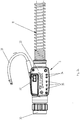
- Figure 2A schematically shows a front view of the control system 6.
- the control system 6 is mounted between the connector 30 and the cable bundle 11.
- the control system 6 comprises a control panel 33 that in turn comprises an on/off button 32 suited to switch the control system 6 on/off, warning lights 34 that signal the status of the control system 6.
- push buttons 35 by means of which the operator can set some parameters of the control system, for example parameters related to the welding process.
- the pipe 31 connects the control system to the cooling circuit of the torch 1, where provided.
- FIG. 2B shows a block diagram of the components of the control system 6.
- the microprocessor 13, included inside the control system 6, comprises an interface for connection with the button 8.
- the connection interface comprises a low-pass filter 16.
- the low-pass filter 16 is preferably of the capacitive type. Preferably, there is one low-pass filter 16 for each one of the one or more control cables 11a of the cable bundle 11.
- the low-pass filter 16 makes it possible to filter the high frequency disturbances that otherwise would alter the signal received by the microprocessor 13. The disturbances get into one or more control cables 11a of the cable bundle 11 by induction, due to the proximity of the one or more control cables 11a to the power supply cables 11b of the torch 1 that are also present in the cable bundle 11.
- the connection interface between the microprocessor 13 and the generator 4 preferably comprises a galvanic isolation element 14 for each one of the one or more control cables 11a.
- the galvanic isolation element 14 may comprise a relay, preferably in the solid state, or an optoisolator preferably comprising a photodiode/photocell pair. In this way, the potential of the generator 4 remains uncoupled from the potential of the microprocessor 13, making the latter unaffected by any fluctuations. The isolation obtained through an optoisolator is advantageous from the point of view of energy consumption.
- the microprocessor 13 is furthermore connected to a current sensor 15 and to the first transmission/reception means 7.
- the current sensor 15 makes it possible to detect the presence of welding current supplied by the generator 4 in the cable bundle 11 and to measure its intensity. Its components are better described with reference to Figures 3A and 3B .
- the microprocessor 13 thus receives information from the current sensor 15 when current starts flowing through the power supply cables 11b of the cable bundle 11. If the moment when the welding current starts flowing is known, the microprocessor 13 is capable of calculating the total interval of time during which the welding current flows through the cable bundle 11.
- the first transmission/reception means 7 make it possible to communicate the data received, processed and/or transmitted by the microprocessor 13 to the other components of the welding system, in particular to the protection unit.
- the first transmission/reception means 7 preferably comprise a radiofrequency unit.
- Said radiofrequency unit is preferably of the Bluetooth® type.
- the first transmission/reception means 7 thus preferably operate in wireless mode and therefore make the structure of the entire welding system lighter.
- first transmission/reception means 7 are on and/or are connected to other transmission/reception means, this is properly signalled by the warning lights 34 on the control panel 33 of the control means 6.
- Figure 3 schematically shows a 3D view ( Figure 3A ) and a sectional view ( Figure 3B ) of a detail of the welding system shown in Figure 1 .
- Figure 3 shows the components of the current sensor 15 of the control system 6.
- Figure 3A shows a 3D view of the current sensor 15, which is suited to detect the presence of current flowing through the cable bundle 11 and in particular the one or more power supply cables 11b and to measure its intensity.
- the current sensor 15 preferably comprises a ferromagnetic circuit 19 cooperating with a Hall sensor 18.
- the ferromagnetic circuit 19 comprises a C-shaped element arranged in such a way as to at least partially envelope one or more power supply cables 11b of the cable bundle 11.
- the ferromagnetic circuit 19 may comprise two C-shaped elements arranged in such a way as to completely envelop one or more power supply cables 11b of the cable bundle 11.
- the Hall sensor 18 is positioned between two adjacent C-shaped elements.
- the ferromagnetic circuit 19 is protected by a closing container 17.
- the current sensor 15 furthermore communicates to the microprocessor 13 the presence of current and its intensity, thus allowing the microprocessor 13 to automatically recognize the operating mode of the generator 4: 2T or 4T mode. This will be useful to determine the darkening mode of the protection screen 3 included in the protection unit, as explained here below with reference to Figure 4 . In this way, the operator is not required to perform additional settings of the system, since the operating mode is recognized automatically through the reading of the welding current and based on the status of the torch button (8).
- Figure 3B shows the sensor 15 along a cross section that is perpendicular to the cable bundle 11.
- Figure 4 schematically shows a detail of the welding system shown in Figure 1 . More particularly, Figure 4 shows a block diagram of the components included in the protection unit.
- the protection unit as better described below, allows the operator to protect his/her eyes from the radiation produced by the welding arc 10.
- the protection unit preferably comprises a protection helmet 2 (not shown in the figure but visible in Figure 1 ) that can be worn by the operator during the welding process.
- the signal indicating that current is flowing through the one or more control cables 11a belonging to the cable bundle 11 reaches the first microprocessor 13.
- the first transmission/reception means 7 included in the control system 6 it is possible to transmit the signal indicating that the button 8 has been pressed - and that, therefore, the operator intends to start the welding operations - to the second transmission/reception means 12 included in the protection unit.
- the second transmission/reception means 12 preferably comprise a radiofrequency unit.
- said radiofrequency unit is of the Bluetooth® type. Therefore, the second transmission/reception means 12 preferably operate in a wireless mode and thus make the structure of the entire welding system lighter. Therefore, through the control system 23 of the protection screen 3, the second microprocessor 20 communicates to the protection screen 3 that the darkening phase can be started.
- the informaton is transferred from the protection unit to the control system 6.
- the microprocessor 13 informs the generator 4 that the button 8 has been pressed. Only at this point the generator 4 will be informed of the position of the button 8 and will start supplying current for the welding process.
- the screen 3 will be dark before the supply of welding current by the generator 4 and therefore before the formation of the welding arc 10. In this way, the operator's eyes are never exposed to the radiation emitted by the welding arc 10.
- the protection screen 3 preferably comprises an LCD filter.
- an LCD filter is substantially constituted by several layers comprising polaroid films, glass and LCDs.
- An LCD filter filters and dims light at certain wavelenghts and, changing the control voltage Vc applied to it, it is possible to vary the degree of light filtering/dimming for the different wavelengths, in particular for the wavelengths in the visible spectrum.
- the degree of darkening (the term "darkening" means the filtration and/or attenuation of the radiation at a certain wavelength) of an LCD filter is measured in DIN degrees.
- the desired DIN degree is supplied by the operator as an input, for example through the buttons 37 on the control panel 36 of the protection unit shown in Figure 1 and 4 .
- the DIN degree can be set automatically by the microprocessor 20 that measures the light radiation emitted by the welding arc by means of the sensor 21 and converts it in the required DIN degree based on a table stored in the microprocessor 20 and/or in a memory unit, thus obtaining the control voltage Vc of the LCD filter.
- the value of the control voltage Vc that the control system 23 calculates as an input for the protection screen 3 depends on the welding parameters and on some environmental parameters like, for example, the temperature of the protection unit.
- the second microprocessor 20 has at its disposal a table in which each DIN degree corresponds to a set of possible values of the applicable control voltage Vc. Even more particularly, for each temperature interval within which the temperature of the LCD filter is included, there is a corresponding specific control voltage Vc, for each DIN degree. Therefore, the second microprocessor 20. once having received the value of the temperature of the LCD filter from the temperature sensor 23, verifies the temperature range within which the filter temperature is included and then applies the corresponding control voltage Vc, based on the DIN degree selected by the operator.
- the protection unit When the operator wants to interrupt the welding operations, the information is transmitted to the protection unit through the transmission/reception means 7.
- the delay with which the opening of the protection screen 3 takes place is calculated based on the welding time, that is, based on the time during which the current sensor 15 has measured the passage of current inside the cable bundle 11. In any case, the delay never exceeds a preset time, for example 1 sec.
- the darkening of the protection screen 3 is ensured, in any case, by a system of optical sensors 21 included in the protection unit.
- the optical sensors 21 in fact, indepedently of the communication system described above, detect the presence of the welding radiation and, through the reading system 22 of the optical sensor, communicate to the protection screen 3 that the darkening phase can be started.
- the protection unit may comprise, furthermore, transducer means 24.
- the transducer means 24 comprise, for example, a display unit 26, a microphone 25 and/or an acoustic diffuser 29 intended to allow the operator to communicate with the main unit and/or the external environment, for example the company's data network.
- the operator can read the data sent by the main unit and thus get to know the data relating to the welding and/or cutting process.
- the microphone 25 and/or the acoustic diffuser 27 the operator can also communicate with the external environment in relation to both the welding and/or cutting data and any necessary service communication.
- Figure 5 schematically shows a further detail of a welding and/or cutting system. More particularly. Figure 5 schematically shows the data collection/transmission unit.
- the data collection/transmission unit mainly comprises a data collection system 27 that in the preferred embodiment shown in the figures is included in the control system 6. as well as a set of sensors 41, 42. 43, 15.
- the sensors 41, 42, 43, 15 are preferably included in the connection element 40 that comprises also the power supply cable 11b, the wire guide sheath with the welding wire, the water pipe of the cooling system and the gas pipe coming from the cylinder 28.
- the sensors 41, 42, 43, 15. conveniently positioned in the welding system, supply the data collection system 27 with data concerning the wire speed, the flow rate of the gas emitted by the gas cylinder 28, the welding voltage and the flow rate and temperature of the liquid circulating in the torch cooling circuit, where provided.
- the sensors communicate with the data collection/transmission system 27 via a wired or wireless connection.
- the sensor 41 that measures the gas flow rate can be a differential pressure sensor and/or an absolute pressure sensor, in the case where the geometry of the gas pipe is known. Alternatively, a volumetric flow sensor can be used.
- the sensor 43 that measures the liquid flow rate in the cooling circuit can be a differential pressure sensor and/or an absolute pressure sensor, in the case where the geometry of the water pipe is known. Alternatively, a volumetric flow sensor can be used.
- the liquid temperature is measured by a temperature sensor of the ptc and ntc type that transduces the temperature into an electrical signal.
- the data collection/transmission system 27 collects and/or reads and/or stores the welding data that are transmitted to it.
- the data collection/transmission system 27 may also comprise software for processing the received data.
- the data collected by the data collection/transmission system 27 can be transmitted via a wired or wireless connection to the microprocessor 13 included in the control system 6, to the protection unit and/or to the external environment, for example the company's data network.
- the operator can be instantaneously informed on the welding parameters that he/she is using, for example by displaying them on the display unit 26 or listening to them through the diffuser 29 located in the helmet 2, and the same data can also be communicated to the external environment.
- the data can be transmitted to a printing unit in order to print the welding report.
- the data collection/transmission system 27 is positioned inside the control system 6, but it can alternatively be located in any other convenient part of the welding system.
- the welding data can be easily received by any device suitable for this type of wireless communication, for example a PC, a tablet or similar devices.
Landscapes
- Engineering & Computer Science (AREA)
- Mechanical Engineering (AREA)
- Physics & Mathematics (AREA)
- General Engineering & Computer Science (AREA)
- Plasma & Fusion (AREA)
- Optics & Photonics (AREA)
- Arc Welding Control (AREA)
Claims (13)
- Schweiß- und/oder Schneidsystem, Folgendes umfassend:einen Generator (4);eine Schweiß- und/oder Schneideeinheit (1),ein Verbindungselement (40), dazu geeignet, die besagte Schweiß- und/oder Schneideeinheit (1) mit dem besagten Generator (4) zu verbinden,wobei das Verbindungselement (40) einen Kabelstrang (11) umfasst, welcher ein oder mehrere Stromversorgungskabel (11b) und ein oder mehrere Steuerkabel (11a) umfasst, und das eine oder die mehreren Steuerkabel (11a) mit einer Drucktaste (8) des Schweiß- und/oder Schneidbrenners (1) verbunden sind,eine Schutzeinheit, einen Schutzschirm (3) umfassend, der verdunkelt werden kann, und ein Steuerungssystem (6), wobei das besagte Steuerungssystem (6) erste Sende-/Empfangsmittel (7) umfasst, die geeignet sind, mit der besagten Schutzeinheit und/oder mit dem besagten Schutzschirm (3) zusammenzuwirken, um die Verdunkelung des besagten Schutzschirms (3) und/oder den Start/Stopp des Schweiß- und/oder Schneidbogens zu steuern, und einen Mikroprozessor (13),dadurch gekennzeichnet, dassdie besagten Sende-/Empfangsmittel (7) vom Bluetooth-Typ sind, und dadurch, dass der besagte Mikroprozessor (13) eine Verbindungsschnittstelle zur Verbindung mit dem besagten Brenner (1) umfasst, wobei die besagte Schnittstelle wenigstens einen Tiefpassfilter (16) umfasst, der geeignet ist, mit dem/den besagten einen oder mehreren Steuerkabel(n) (11a) des besagten Verbindungselements (40) verbunden zu werden.
- Schweiß- und/oder Schneidesystem (6) nach Patentanspruch 1, dadurch gekennzeichnet, dass die besagten Sende-/Empfangsmittel (7) geeignet sind, mit jeglicher sowohl innerhalb als auch außerhalb des Schweißsystems befindlichen Vorrichtung vom Bluetooth-Typ Informationen auszutauschen.
- Schweiß- und/oder Schneidesystem (6) nach einem jeden der vorstehenden Patentansprüche, dadurch gekennzeichnet, dass es eine Schalttafel (33) umfasst, die Warnlampen (34) umfasst, welche geeignet sind, den Status des besagten Steuerungssystem (6) anzuzeigen, sowie Drucktasten (35) zur Konfiguration des besagten Steuerungssystems (6).
- Schweiß- und/oder Schneidesystem (6) nach Patentanspruch 1, dadurch gekennzeichnet, dass der besagte Tiefpassfilter (16) vom kapazitiven Typ ist.
- Schweiß- und/oder Schneidesystem (6) nach einem jeden der Patentansprüche von 1 bis 4, dadurch gekennzeichnet, dass der besagte Mikroprozessor (13) eine Verbindungsschnittstelle zur Verbindung mit dem besagten Generator (4) umfasst, wobei die besagte Schnittstelle wenigstens ein galvanisches Isolierelement (14) umfasst, das geeignet ist, mit dem/den besagten einen oder mehreren Steuerkabel(n) (11a) des besagten Verbindungselements (40) verbunden zu werden.
- Schweiß- und/oder Schneidesystem (6) nach Patentanspruch 5, dadurch gekennzeichnet, dass das besagte galvanische Isolierelement (14) ein Halbleiterrelais und/oder einen Optoisolator umfasst.
- Schweiß- und/oder Schneidesystem (6) nach einem jeden der vorstehenden Patentansprüche, dadurch gekennzeichnet, dass es einen Stromsensor (15) umfasst, der geeignet ist, den Stromdurchfluss in einem oder mehreren Stromversorgungskabeln (11b) des besagten Verbindungselements (40) zu messen.
- Schweiß- und/oder Schneidesystem nach Patentanspruch 1, dadurch gekennzeichnet, dass die besagte Schutzeinheit zweite Sende-/Empfangsmittel (12) vom Bluetooth-Typ umfasst, die geeignet sind, Daten an die/von den ersten, im Steuerungssystem (6) enthaltenen Sende-/Empfangsmitteln (7) zu senden/zu empfangen.
- Schweiß- und/oder Schneidesystem nach Patentanspruch 1 oder 8, dadurch gekennzeichnet, dass die besagte Schutzeinheit optische Sensoren (21) umfasst, welche geeignet sind, die vom Lichtbogen (10) abgegebene Strahlung zu erfassen.
- Schweiß- und/oder Schneidesystem nach einem jeden der Patentansprüche von 1 bis 9, dadurch gekennzeichnet, dass die besagte Schutzeinheit einen zweiten Mikroprozessor (20) umfasst.
- Schweiß- und/oder Schneidesystem nach einem jeden der Patentansprüche von 1 bis 10, dadurch gekennzeichnet, dass die besagte Schutzeinheit ein Steuerungssystem (23) des besagten Schutzschirms (3) umfasst, das geeignet ist, dem Schutzschirm (3) die Verdunkelungsspannung (Vc) zu kommunizieren.
- Schweiß- und/oder Schneidesystem nach einem jeden der Patentansprüche von 1 bis 11, dadurch gekennzeichnet, dass die besagte Schutzeinheit Wandlermittel (24) umfasst.
- Schweiß- und/oder Schneidesystem nach einem jeden der Patentansprüche von 1 bis 12 und abhängig von Patentanspruch 3, dadurch gekennzeichnet, dass die besagte Schalttafel (33) des besagten Steuerungssystems (6) einen Knopf (32) zum Ein- und Ausschalten des besagten Steuerungssystems (6) umfasst, so dass dieser das System, wenn er sich in der ausgeschalteten Konfiguration befindet, in einen traditionellen Betriebsmodus zurückversetzt, wobei der Brenner (1) unter Umgehung des besagten Steuerungskreises (6) direkt mit dem Generator (4) verbunden ist.
Priority Applications (1)
| Application Number | Priority Date | Filing Date | Title |
|---|---|---|---|
| EP19187876.8A EP3593931B1 (de) | 2014-04-04 | 2015-04-01 | Schweiss- und/oder schneidsystem mit einer steuerungssystem verwendend einer bluetooth-verbindung |
Applications Claiming Priority (2)
| Application Number | Priority Date | Filing Date | Title |
|---|---|---|---|
| ITVI20140089 | 2014-04-04 | ||
| PCT/IB2015/052408 WO2015151050A1 (en) | 2014-04-04 | 2015-04-01 | Control system for welding systems |
Related Child Applications (2)
| Application Number | Title | Priority Date | Filing Date |
|---|---|---|---|
| EP19187876.8A Division EP3593931B1 (de) | 2014-04-04 | 2015-04-01 | Schweiss- und/oder schneidsystem mit einer steuerungssystem verwendend einer bluetooth-verbindung |
| EP19187876.8A Division-Into EP3593931B1 (de) | 2014-04-04 | 2015-04-01 | Schweiss- und/oder schneidsystem mit einer steuerungssystem verwendend einer bluetooth-verbindung |
Publications (2)
| Publication Number | Publication Date |
|---|---|
| EP3126085A1 EP3126085A1 (de) | 2017-02-08 |
| EP3126085B1 true EP3126085B1 (de) | 2019-12-25 |
Family
ID=50877618
Family Applications (2)
| Application Number | Title | Priority Date | Filing Date |
|---|---|---|---|
| EP15720457.9A Active EP3126085B1 (de) | 2014-04-04 | 2015-04-01 | Steuerungssystem für schweisssysteme |
| EP19187876.8A Active EP3593931B1 (de) | 2014-04-04 | 2015-04-01 | Schweiss- und/oder schneidsystem mit einer steuerungssystem verwendend einer bluetooth-verbindung |
Family Applications After (1)
| Application Number | Title | Priority Date | Filing Date |
|---|---|---|---|
| EP19187876.8A Active EP3593931B1 (de) | 2014-04-04 | 2015-04-01 | Schweiss- und/oder schneidsystem mit einer steuerungssystem verwendend einer bluetooth-verbindung |
Country Status (6)
| Country | Link |
|---|---|
| US (1) | US20170021444A1 (de) |
| EP (2) | EP3126085B1 (de) |
| CN (1) | CN106132616B (de) |
| CA (1) | CA2958796A1 (de) |
| ES (1) | ES2774788T3 (de) |
| WO (1) | WO2015151050A1 (de) |
Families Citing this family (10)
| Publication number | Priority date | Publication date | Assignee | Title |
|---|---|---|---|---|
| GB2541721A (en) * | 2015-08-28 | 2017-03-01 | Linde Ag | A sensor module for a fabrication tool |
| US11204394B2 (en) | 2017-09-20 | 2021-12-21 | Esab Ab | External connector and sensor unit for welding equipment |
| CN211187783U (zh) | 2018-08-15 | 2020-08-07 | 泰克曼(南京)电子有限公司 | 自动变光焊接面罩以及配备其的焊接设备 |
| IT201800009774A1 (it) * | 2018-10-25 | 2020-04-25 | Trafimet Group Spa | Elmetto protettivo di saldatura o taglio ed impianto di saldatura o taglio provvisto di tale elmetto |
| CN109172136A (zh) * | 2018-10-29 | 2019-01-11 | 安徽华生机电设备有限公司 | 一种无线自动变光焊帽及其控制系统 |
| IT201800020563A1 (it) * | 2018-12-20 | 2020-06-20 | Jasic Tech Europe S R L | Sistema di saldatura di tipo modulabile |
| EP3767378A1 (de) | 2019-07-19 | 2021-01-20 | 3M Innovative Properties Company | Automatischer dunkelfilter mit vereinfachtem aufbau |
| US12544850B2 (en) * | 2020-07-29 | 2026-02-10 | Illinois Tool Works Inc. | Systems and methods for automatic gouge torch activation |
| DE102022001631B4 (de) * | 2022-05-10 | 2024-11-14 | Christian Meyer | Stromstärkeanzeiger für Schweißhelm |
| CN117226224B (zh) * | 2023-11-16 | 2024-01-23 | 苏芯物联技术(南京)有限公司 | 一种焊接保护气流量实时智能控制方法 |
Citations (1)
| Publication number | Priority date | Publication date | Assignee | Title |
|---|---|---|---|---|
| US20070080154A1 (en) * | 2004-04-16 | 2007-04-12 | Ott Brian L | Remote wire feeder using binary phase shift keying to modulate communications of command/control signals to be transmitted over a weld cable |
Family Cites Families (19)
| Publication number | Priority date | Publication date | Assignee | Title |
|---|---|---|---|---|
| US3222548A (en) * | 1963-09-30 | 1965-12-07 | Richard J Sanford | Rf protection circuit |
| US3562581A (en) * | 1968-03-25 | 1971-02-09 | Arco Corp | Means for and method of stabilizing a plurality of gaseous electric arc discharge devices |
| US4477713A (en) * | 1982-07-09 | 1984-10-16 | Crc Welding Systems, Inc. | Sidewall-matching adaptive control system for welding |
| AT411880B (de) * | 1998-01-13 | 2004-07-26 | Fronius Int Gmbh | Steuervorrichtung für ein schweissgerät |
| AT409239B (de) * | 1998-05-13 | 2002-06-25 | Fronius Schweissmasch | Verfahren zum steuern eines schweissgerätes und steuervorrichtung hierfür |
| AU6670800A (en) * | 1999-08-13 | 2001-03-13 | Fronius Schweissmaschinen Produktion Gmbh & Co. Kg | Data display on a welding screen |
| AT413658B (de) * | 2001-09-12 | 2006-04-15 | Fronius Int Gmbh | Fernregler und bedieneinheit für ein schweissgerät |
| CN201073713Y (zh) * | 2007-04-17 | 2008-06-18 | 中国石油天然气集团公司 | 数字化多功能逆变焊机 |
| US7962967B2 (en) * | 2008-05-09 | 2011-06-21 | Illinois Tool Works Inc. | Weld characteristic communication system for a welding mask |
| AT508094B1 (de) * | 2009-03-31 | 2015-05-15 | Fronius Int Gmbh | Verfahren und vorrichtung zur bedienung einer mit einem handbetätigten arbeitsgerät verbundenen stromquelle |
| EP2253407B1 (de) * | 2009-05-22 | 2011-07-20 | C.R.F. Società Consortile per Azioni | System zur Überwachung von Lichtbogenschweißverfahren und entsprechendes Überwachungsverfahren |
| KR101129593B1 (ko) * | 2009-12-24 | 2012-03-28 | 주식회사 오토스윙 | 무선 통신 기능을 갖는 눈부심 방지장치 |
| KR101240980B1 (ko) * | 2010-11-18 | 2013-03-11 | 기아자동차주식회사 | 레이저 용접 품질 검사 방법 및 장치 |
| US9566192B2 (en) * | 2012-05-04 | 2017-02-14 | Illinois Tool Works Inc. | Welding helmet for detecting arc data |
| DE102012104348A1 (de) * | 2012-05-21 | 2013-11-21 | Konrad Slanec | Berührungsloses, hochgenaues Stromsensorsystem |
| US10259067B2 (en) * | 2012-06-04 | 2019-04-16 | Illinois Tool Works Inc. | Remote polarity detection and control for welding process |
| US9430438B2 (en) * | 2014-03-08 | 2016-08-30 | Atieva, Inc. | Communication bus with zero power wake function |
| US9943924B2 (en) * | 2014-03-28 | 2018-04-17 | Illinois Tool Works Inc. | Systems and methods for wireless control of an engine-driven welding power supply |
| US10493552B2 (en) * | 2014-04-04 | 2019-12-03 | Illinois Tool Works Inc. | Systems and methods for measuring voltage and current in a torch |
-
2015
- 2015-04-01 CN CN201580017368.1A patent/CN106132616B/zh not_active Expired - Fee Related
- 2015-04-01 CA CA2958796A patent/CA2958796A1/en not_active Abandoned
- 2015-04-01 EP EP15720457.9A patent/EP3126085B1/de active Active
- 2015-04-01 EP EP19187876.8A patent/EP3593931B1/de active Active
- 2015-04-01 US US15/301,390 patent/US20170021444A1/en not_active Abandoned
- 2015-04-01 ES ES15720457T patent/ES2774788T3/es active Active
- 2015-04-01 WO PCT/IB2015/052408 patent/WO2015151050A1/en not_active Ceased
Patent Citations (1)
| Publication number | Priority date | Publication date | Assignee | Title |
|---|---|---|---|---|
| US20070080154A1 (en) * | 2004-04-16 | 2007-04-12 | Ott Brian L | Remote wire feeder using binary phase shift keying to modulate communications of command/control signals to be transmitted over a weld cable |
Also Published As
| Publication number | Publication date |
|---|---|
| WO2015151050A1 (en) | 2015-10-08 |
| ES2774788T3 (es) | 2020-07-22 |
| CN106132616A (zh) | 2016-11-16 |
| EP3593931A1 (de) | 2020-01-15 |
| EP3593931B1 (de) | 2022-01-26 |
| EP3126085A1 (de) | 2017-02-08 |
| CN106132616B (zh) | 2018-09-04 |
| US20170021444A1 (en) | 2017-01-26 |
| CA2958796A1 (en) | 2015-10-08 |
Similar Documents
| Publication | Publication Date | Title |
|---|---|---|
| EP3126085B1 (de) | Steuerungssystem für schweisssysteme | |
| EP3125841B1 (de) | Schweiss- und/oder schneideinheit mit einem sensor zur erfassung/messung vom schweiss- und/oder schneidstrom | |
| US20110010815A1 (en) | Welding helmet including anti-blinding device to selectively and conveniently control welding operation and grinding operation | |
| US12533262B2 (en) | Auto-darkening welding helmet and welding apparatus equipped with the same | |
| US11090192B2 (en) | Personal protective system tool communication adapter | |
| KR101131475B1 (ko) | 용접 작업과 그라인딩 작업을 선택적으로 편리하게 제어하는 눈부심 방지장치를 포함한 용접헬멧 | |
| KR20100041287A (ko) | 기능성 디스플레이 눈부심 방지 장치 | |
| CN101744683A (zh) | 不取下就能控制液晶显示遮挡护目镜的焊接面罩 | |
| WO2015036652A1 (en) | Power supply of a welding helmet | |
| WO2018070117A1 (ja) | 熱加工用トーチ、熱加工システム、簡易電源装置、および、確認方法 | |
| CN109937113A (zh) | 焊炬和焊接系统 | |
| EP3501718A1 (de) | Brenner zur wärmebehandlung, energiequellenvorrichtung, drahtvorschubvorrichtung und wärmebehandlungssystem | |
| CN212137814U (zh) | 一种ar焊接头盔及焊接设备 | |
| CN111601075B (zh) | 一种ar焊接头盔及焊接设备 | |
| JP3222444B2 (ja) | ディジタル通信式溶接装置 | |
| CN111671567A (zh) | 一种视频显示焊接头盔及焊接设备 | |
| KR101673416B1 (ko) | 용접용 스마트 보안경 | |
| CN105921477A (zh) | 一种新型实验室通风柜 | |
| CN210297231U (zh) | 一种电焊机的漏电保护装置 | |
| CN213276867U (zh) | 一种多功能消防员呼救器 | |
| IT201800009774A1 (it) | Elmetto protettivo di saldatura o taglio ed impianto di saldatura o taglio provvisto di tale elmetto | |
| CN208476474U (zh) | 一种特种耐高温高压炉漏液检测装置 | |
| CN104408871A (zh) | 安全测试仪 |
Legal Events
| Date | Code | Title | Description |
|---|---|---|---|
| STAA | Information on the status of an ep patent application or granted ep patent |
Free format text: STATUS: THE INTERNATIONAL PUBLICATION HAS BEEN MADE |
|
| PUAI | Public reference made under article 153(3) epc to a published international application that has entered the european phase |
Free format text: ORIGINAL CODE: 0009012 |
|
| STAA | Information on the status of an ep patent application or granted ep patent |
Free format text: STATUS: REQUEST FOR EXAMINATION WAS MADE |
|
| 17P | Request for examination filed |
Effective date: 20161014 |
|
| AK | Designated contracting states |
Kind code of ref document: A1 Designated state(s): AL AT BE BG CH CY CZ DE DK EE ES FI FR GB GR HR HU IE IS IT LI LT LU LV MC MK MT NL NO PL PT RO RS SE SI SK SM TR |
|
| AX | Request for extension of the european patent |
Extension state: BA ME |
|
| DAV | Request for validation of the european patent (deleted) | ||
| DAX | Request for extension of the european patent (deleted) | ||
| STAA | Information on the status of an ep patent application or granted ep patent |
Free format text: STATUS: EXAMINATION IS IN PROGRESS |
|
| 17Q | First examination report despatched |
Effective date: 20190215 |
|
| GRAP | Despatch of communication of intention to grant a patent |
Free format text: ORIGINAL CODE: EPIDOSNIGR1 |
|
| STAA | Information on the status of an ep patent application or granted ep patent |
Free format text: STATUS: GRANT OF PATENT IS INTENDED |
|
| INTG | Intention to grant announced |
Effective date: 20190731 |
|
| GRAS | Grant fee paid |
Free format text: ORIGINAL CODE: EPIDOSNIGR3 |
|
| GRAA | (expected) grant |
Free format text: ORIGINAL CODE: 0009210 |
|
| STAA | Information on the status of an ep patent application or granted ep patent |
Free format text: STATUS: THE PATENT HAS BEEN GRANTED |
|
| AK | Designated contracting states |
Kind code of ref document: B1 Designated state(s): AL AT BE BG CH CY CZ DE DK EE ES FI FR GB GR HR HU IE IS IT LI LT LU LV MC MK MT NL NO PL PT RO RS SE SI SK SM TR |
|
| REG | Reference to a national code |
Ref country code: GB Ref legal event code: FG4D |
|
| REG | Reference to a national code |
Ref country code: CH Ref legal event code: EP |
|
| REG | Reference to a national code |
Ref country code: AT Ref legal event code: REF Ref document number: 1216624 Country of ref document: AT Kind code of ref document: T Effective date: 20200115 |
|
| REG | Reference to a national code |
Ref country code: DE Ref legal event code: R096 Ref document number: 602015044236 Country of ref document: DE |
|
| REG | Reference to a national code |
Ref country code: IE Ref legal event code: FG4D |
|
| REG | Reference to a national code |
Ref country code: CH Ref legal event code: NV Representative=s name: SEDIN SA, CH |
|
| REG | Reference to a national code |
Ref country code: NL Ref legal event code: FP |
|
| REG | Reference to a national code |
Ref country code: SE Ref legal event code: TRGR |
|
| PG25 | Lapsed in a contracting state [announced via postgrant information from national office to epo] |
Ref country code: LV Free format text: LAPSE BECAUSE OF FAILURE TO SUBMIT A TRANSLATION OF THE DESCRIPTION OR TO PAY THE FEE WITHIN THE PRESCRIBED TIME-LIMIT Effective date: 20191225 Ref country code: GR Free format text: LAPSE BECAUSE OF FAILURE TO SUBMIT A TRANSLATION OF THE DESCRIPTION OR TO PAY THE FEE WITHIN THE PRESCRIBED TIME-LIMIT Effective date: 20200326 Ref country code: LT Free format text: LAPSE BECAUSE OF FAILURE TO SUBMIT A TRANSLATION OF THE DESCRIPTION OR TO PAY THE FEE WITHIN THE PRESCRIBED TIME-LIMIT Effective date: 20191225 Ref country code: BG Free format text: LAPSE BECAUSE OF FAILURE TO SUBMIT A TRANSLATION OF THE DESCRIPTION OR TO PAY THE FEE WITHIN THE PRESCRIBED TIME-LIMIT Effective date: 20200325 Ref country code: NO Free format text: LAPSE BECAUSE OF FAILURE TO SUBMIT A TRANSLATION OF THE DESCRIPTION OR TO PAY THE FEE WITHIN THE PRESCRIBED TIME-LIMIT Effective date: 20200325 Ref country code: FI Free format text: LAPSE BECAUSE OF FAILURE TO SUBMIT A TRANSLATION OF THE DESCRIPTION OR TO PAY THE FEE WITHIN THE PRESCRIBED TIME-LIMIT Effective date: 20191225 |
|
| REG | Reference to a national code |
Ref country code: LT Ref legal event code: MG4D |
|
| PG25 | Lapsed in a contracting state [announced via postgrant information from national office to epo] |
Ref country code: HR Free format text: LAPSE BECAUSE OF FAILURE TO SUBMIT A TRANSLATION OF THE DESCRIPTION OR TO PAY THE FEE WITHIN THE PRESCRIBED TIME-LIMIT Effective date: 20191225 Ref country code: RS Free format text: LAPSE BECAUSE OF FAILURE TO SUBMIT A TRANSLATION OF THE DESCRIPTION OR TO PAY THE FEE WITHIN THE PRESCRIBED TIME-LIMIT Effective date: 20191225 |
|
| PG25 | Lapsed in a contracting state [announced via postgrant information from national office to epo] |
Ref country code: AL Free format text: LAPSE BECAUSE OF FAILURE TO SUBMIT A TRANSLATION OF THE DESCRIPTION OR TO PAY THE FEE WITHIN THE PRESCRIBED TIME-LIMIT Effective date: 20191225 |
|
| REG | Reference to a national code |
Ref country code: ES Ref legal event code: FG2A Ref document number: 2774788 Country of ref document: ES Kind code of ref document: T3 Effective date: 20200722 |
|
| PG25 | Lapsed in a contracting state [announced via postgrant information from national office to epo] |
Ref country code: CZ Free format text: LAPSE BECAUSE OF FAILURE TO SUBMIT A TRANSLATION OF THE DESCRIPTION OR TO PAY THE FEE WITHIN THE PRESCRIBED TIME-LIMIT Effective date: 20191225 Ref country code: PT Free format text: LAPSE BECAUSE OF FAILURE TO SUBMIT A TRANSLATION OF THE DESCRIPTION OR TO PAY THE FEE WITHIN THE PRESCRIBED TIME-LIMIT Effective date: 20200520 Ref country code: RO Free format text: LAPSE BECAUSE OF FAILURE TO SUBMIT A TRANSLATION OF THE DESCRIPTION OR TO PAY THE FEE WITHIN THE PRESCRIBED TIME-LIMIT Effective date: 20191225 Ref country code: EE Free format text: LAPSE BECAUSE OF FAILURE TO SUBMIT A TRANSLATION OF THE DESCRIPTION OR TO PAY THE FEE WITHIN THE PRESCRIBED TIME-LIMIT Effective date: 20191225 |
|
| PG25 | Lapsed in a contracting state [announced via postgrant information from national office to epo] |
Ref country code: SK Free format text: LAPSE BECAUSE OF FAILURE TO SUBMIT A TRANSLATION OF THE DESCRIPTION OR TO PAY THE FEE WITHIN THE PRESCRIBED TIME-LIMIT Effective date: 20191225 Ref country code: IS Free format text: LAPSE BECAUSE OF FAILURE TO SUBMIT A TRANSLATION OF THE DESCRIPTION OR TO PAY THE FEE WITHIN THE PRESCRIBED TIME-LIMIT Effective date: 20200425 Ref country code: SM Free format text: LAPSE BECAUSE OF FAILURE TO SUBMIT A TRANSLATION OF THE DESCRIPTION OR TO PAY THE FEE WITHIN THE PRESCRIBED TIME-LIMIT Effective date: 20191225 |
|
| REG | Reference to a national code |
Ref country code: DE Ref legal event code: R097 Ref document number: 602015044236 Country of ref document: DE |
|
| PG25 | Lapsed in a contracting state [announced via postgrant information from national office to epo] |
Ref country code: DK Free format text: LAPSE BECAUSE OF FAILURE TO SUBMIT A TRANSLATION OF THE DESCRIPTION OR TO PAY THE FEE WITHIN THE PRESCRIBED TIME-LIMIT Effective date: 20191225 |
|
| PLBE | No opposition filed within time limit |
Free format text: ORIGINAL CODE: 0009261 |
|
| STAA | Information on the status of an ep patent application or granted ep patent |
Free format text: STATUS: NO OPPOSITION FILED WITHIN TIME LIMIT |
|
| PG25 | Lapsed in a contracting state [announced via postgrant information from national office to epo] |
Ref country code: MC Free format text: LAPSE BECAUSE OF FAILURE TO SUBMIT A TRANSLATION OF THE DESCRIPTION OR TO PAY THE FEE WITHIN THE PRESCRIBED TIME-LIMIT Effective date: 20191225 Ref country code: SI Free format text: LAPSE BECAUSE OF FAILURE TO SUBMIT A TRANSLATION OF THE DESCRIPTION OR TO PAY THE FEE WITHIN THE PRESCRIBED TIME-LIMIT Effective date: 20191225 |
|
| 26N | No opposition filed |
Effective date: 20200928 |
|
| PG25 | Lapsed in a contracting state [announced via postgrant information from national office to epo] |
Ref country code: LU Free format text: LAPSE BECAUSE OF NON-PAYMENT OF DUE FEES Effective date: 20200401 |
|
| REG | Reference to a national code |
Ref country code: BE Ref legal event code: MM Effective date: 20200430 |
|
| PG25 | Lapsed in a contracting state [announced via postgrant information from national office to epo] |
Ref country code: BE Free format text: LAPSE BECAUSE OF NON-PAYMENT OF DUE FEES Effective date: 20200430 Ref country code: PL Free format text: LAPSE BECAUSE OF FAILURE TO SUBMIT A TRANSLATION OF THE DESCRIPTION OR TO PAY THE FEE WITHIN THE PRESCRIBED TIME-LIMIT Effective date: 20191225 |
|
| PG25 | Lapsed in a contracting state [announced via postgrant information from national office to epo] |
Ref country code: IE Free format text: LAPSE BECAUSE OF NON-PAYMENT OF DUE FEES Effective date: 20200401 |
|
| PGFP | Annual fee paid to national office [announced via postgrant information from national office to epo] |
Ref country code: NL Payment date: 20210415 Year of fee payment: 7 |
|
| PG25 | Lapsed in a contracting state [announced via postgrant information from national office to epo] |
Ref country code: TR Free format text: LAPSE BECAUSE OF FAILURE TO SUBMIT A TRANSLATION OF THE DESCRIPTION OR TO PAY THE FEE WITHIN THE PRESCRIBED TIME-LIMIT Effective date: 20191225 Ref country code: MT Free format text: LAPSE BECAUSE OF FAILURE TO SUBMIT A TRANSLATION OF THE DESCRIPTION OR TO PAY THE FEE WITHIN THE PRESCRIBED TIME-LIMIT Effective date: 20191225 Ref country code: CY Free format text: LAPSE BECAUSE OF FAILURE TO SUBMIT A TRANSLATION OF THE DESCRIPTION OR TO PAY THE FEE WITHIN THE PRESCRIBED TIME-LIMIT Effective date: 20191225 |
|
| PG25 | Lapsed in a contracting state [announced via postgrant information from national office to epo] |
Ref country code: MK Free format text: LAPSE BECAUSE OF FAILURE TO SUBMIT A TRANSLATION OF THE DESCRIPTION OR TO PAY THE FEE WITHIN THE PRESCRIBED TIME-LIMIT Effective date: 20191225 |
|
| REG | Reference to a national code |
Ref country code: NL Ref legal event code: MM Effective date: 20220501 |
|
| PG25 | Lapsed in a contracting state [announced via postgrant information from national office to epo] |
Ref country code: NL Free format text: LAPSE BECAUSE OF NON-PAYMENT OF DUE FEES Effective date: 20220501 |
|
| PGFP | Annual fee paid to national office [announced via postgrant information from national office to epo] |
Ref country code: FR Payment date: 20230328 Year of fee payment: 9 |
|
| PGFP | Annual fee paid to national office [announced via postgrant information from national office to epo] |
Ref country code: SE Payment date: 20230327 Year of fee payment: 9 Ref country code: IT Payment date: 20230315 Year of fee payment: 9 Ref country code: GB Payment date: 20230323 Year of fee payment: 9 |
|
| P01 | Opt-out of the competence of the unified patent court (upc) registered |
Effective date: 20230517 |
|
| PGFP | Annual fee paid to national office [announced via postgrant information from national office to epo] |
Ref country code: ES Payment date: 20230511 Year of fee payment: 9 Ref country code: DE Payment date: 20230321 Year of fee payment: 9 Ref country code: CH Payment date: 20230502 Year of fee payment: 9 |
|
| PGFP | Annual fee paid to national office [announced via postgrant information from national office to epo] |
Ref country code: AT Payment date: 20230327 Year of fee payment: 9 |
|
| REG | Reference to a national code |
Ref country code: DE Ref legal event code: R119 Ref document number: 602015044236 Country of ref document: DE |
|
| REG | Reference to a national code |
Ref country code: CH Ref legal event code: PL |
|
| REG | Reference to a national code |
Ref country code: SE Ref legal event code: EUG |
|
| REG | Reference to a national code |
Ref country code: AT Ref legal event code: MM01 Ref document number: 1216624 Country of ref document: AT Kind code of ref document: T Effective date: 20240401 |
|
| GBPC | Gb: european patent ceased through non-payment of renewal fee |
Effective date: 20240401 |
|
| PG25 | Lapsed in a contracting state [announced via postgrant information from national office to epo] |
Ref country code: DE Free format text: LAPSE BECAUSE OF NON-PAYMENT OF DUE FEES Effective date: 20241105 |
|
| PG25 | Lapsed in a contracting state [announced via postgrant information from national office to epo] |
Ref country code: GB Free format text: LAPSE BECAUSE OF NON-PAYMENT OF DUE FEES Effective date: 20240401 |
|
| PG25 | Lapsed in a contracting state [announced via postgrant information from national office to epo] |
Ref country code: FR Free format text: LAPSE BECAUSE OF NON-PAYMENT OF DUE FEES Effective date: 20240430 |
|
| PG25 | Lapsed in a contracting state [announced via postgrant information from national office to epo] |
Ref country code: AT Free format text: LAPSE BECAUSE OF NON-PAYMENT OF DUE FEES Effective date: 20240401 |
|
| PG25 | Lapsed in a contracting state [announced via postgrant information from national office to epo] |
Ref country code: GB Free format text: LAPSE BECAUSE OF NON-PAYMENT OF DUE FEES Effective date: 20240401 Ref country code: FR Free format text: LAPSE BECAUSE OF NON-PAYMENT OF DUE FEES Effective date: 20240430 Ref country code: DE Free format text: LAPSE BECAUSE OF NON-PAYMENT OF DUE FEES Effective date: 20241105 Ref country code: AT Free format text: LAPSE BECAUSE OF NON-PAYMENT OF DUE FEES Effective date: 20240401 Ref country code: CH Free format text: LAPSE BECAUSE OF NON-PAYMENT OF DUE FEES Effective date: 20240430 |
|
| REG | Reference to a national code |
Ref country code: AT Ref legal event code: UEP Ref document number: 1216624 Country of ref document: AT Kind code of ref document: T Effective date: 20191225 |
|
| PG25 | Lapsed in a contracting state [announced via postgrant information from national office to epo] |
Ref country code: IT Free format text: LAPSE BECAUSE OF NON-PAYMENT OF DUE FEES Effective date: 20240401 |
|
| REG | Reference to a national code |
Ref country code: ES Ref legal event code: FD2A Effective date: 20250526 |
|
| PG25 | Lapsed in a contracting state [announced via postgrant information from national office to epo] |
Ref country code: ES Free format text: LAPSE BECAUSE OF NON-PAYMENT OF DUE FEES Effective date: 20240402 |
|
| PG25 | Lapsed in a contracting state [announced via postgrant information from national office to epo] |
Ref country code: SE Free format text: LAPSE BECAUSE OF NON-PAYMENT OF DUE FEES Effective date: 20240402 |