EP3124318A1 - Sitzplatzbelegungsstatusdetektionsvorrichtung - Google Patents
Sitzplatzbelegungsstatusdetektionsvorrichtung Download PDFInfo
- Publication number
- EP3124318A1 EP3124318A1 EP16175037.7A EP16175037A EP3124318A1 EP 3124318 A1 EP3124318 A1 EP 3124318A1 EP 16175037 A EP16175037 A EP 16175037A EP 3124318 A1 EP3124318 A1 EP 3124318A1
- Authority
- EP
- European Patent Office
- Prior art keywords
- seat
- occupancy
- load
- state
- sensor
- Prior art date
- Legal status (The legal status is an assumption and is not a legal conclusion. Google has not performed a legal analysis and makes no representation as to the accuracy of the status listed.)
- Granted
Links
- 238000001514 detection method Methods 0.000 title claims abstract description 70
- 230000005856 abnormality Effects 0.000 claims abstract description 37
- 238000012937 correction Methods 0.000 claims description 23
- 230000036544 posture Effects 0.000 description 52
- 238000000034 method Methods 0.000 description 18
- 239000012528 membrane Substances 0.000 description 16
- 230000008569 process Effects 0.000 description 12
- 230000003542 behavioural effect Effects 0.000 description 9
- 238000012545 processing Methods 0.000 description 5
- 230000007704 transition Effects 0.000 description 5
- 230000008859 change Effects 0.000 description 4
- 239000000463 material Substances 0.000 description 4
- 230000000694 effects Effects 0.000 description 2
- 239000011347 resin Substances 0.000 description 2
- 229920005989 resin Polymers 0.000 description 2
- 238000004891 communication Methods 0.000 description 1
- 238000012790 confirmation Methods 0.000 description 1
- 230000003247 decreasing effect Effects 0.000 description 1
- 230000003111 delayed effect Effects 0.000 description 1
- 230000006872 improvement Effects 0.000 description 1
- 125000006850 spacer group Chemical group 0.000 description 1
Images


Classifications
-
- G—PHYSICS
- G07—CHECKING-DEVICES
- G07C—TIME OR ATTENDANCE REGISTERS; REGISTERING OR INDICATING THE WORKING OF MACHINES; GENERATING RANDOM NUMBERS; VOTING OR LOTTERY APPARATUS; ARRANGEMENTS, SYSTEMS OR APPARATUS FOR CHECKING NOT PROVIDED FOR ELSEWHERE
- G07C5/00—Registering or indicating the working of vehicles
- G07C5/08—Registering or indicating performance data other than driving, working, idle, or waiting time, with or without registering driving, working, idle or waiting time
- G07C5/0808—Diagnosing performance data
-
- B—PERFORMING OPERATIONS; TRANSPORTING
- B60—VEHICLES IN GENERAL
- B60N—SEATS SPECIALLY ADAPTED FOR VEHICLES; VEHICLE PASSENGER ACCOMMODATION NOT OTHERWISE PROVIDED FOR
- B60N2/00—Seats specially adapted for vehicles; Arrangement or mounting of seats in vehicles
- B60N2/002—Seats provided with an occupancy detection means mounted therein or thereon
-
- B—PERFORMING OPERATIONS; TRANSPORTING
- B60—VEHICLES IN GENERAL
- B60R—VEHICLES, VEHICLE FITTINGS, OR VEHICLE PARTS, NOT OTHERWISE PROVIDED FOR
- B60R21/00—Arrangements or fittings on vehicles for protecting or preventing injuries to occupants or pedestrians in case of accidents or other traffic risks
- B60R21/01—Electrical circuits for triggering passive safety arrangements, e.g. airbags, safety belt tighteners, in case of vehicle accidents or impending vehicle accidents
- B60R21/015—Electrical circuits for triggering passive safety arrangements, e.g. airbags, safety belt tighteners, in case of vehicle accidents or impending vehicle accidents including means for detecting the presence or position of passengers, passenger seats or child seats, and the related safety parameters therefor, e.g. speed or timing of airbag inflation in relation to occupant position or seat belt use
- B60R21/01512—Passenger detection systems
- B60R21/01516—Passenger detection systems using force or pressure sensing means
-
- G—PHYSICS
- G01—MEASURING; TESTING
- G01G—WEIGHING
- G01G19/00—Weighing apparatus or methods adapted for special purposes not provided for in the preceding groups
- G01G19/40—Weighing apparatus or methods adapted for special purposes not provided for in the preceding groups with provisions for indicating, recording, or computing price or other quantities dependent on the weight
- G01G19/413—Weighing apparatus or methods adapted for special purposes not provided for in the preceding groups with provisions for indicating, recording, or computing price or other quantities dependent on the weight using electromechanical or electronic computing means
- G01G19/414—Weighing apparatus or methods adapted for special purposes not provided for in the preceding groups with provisions for indicating, recording, or computing price or other quantities dependent on the weight using electromechanical or electronic computing means using electronic computing means only
- G01G19/4142—Weighing apparatus or methods adapted for special purposes not provided for in the preceding groups with provisions for indicating, recording, or computing price or other quantities dependent on the weight using electromechanical or electronic computing means using electronic computing means only for controlling activation of safety devices, e.g. airbag systems
-
- B—PERFORMING OPERATIONS; TRANSPORTING
- B60—VEHICLES IN GENERAL
- B60R—VEHICLES, VEHICLE FITTINGS, OR VEHICLE PARTS, NOT OTHERWISE PROVIDED FOR
- B60R21/00—Arrangements or fittings on vehicles for protecting or preventing injuries to occupants or pedestrians in case of accidents or other traffic risks
- B60R21/01—Electrical circuits for triggering passive safety arrangements, e.g. airbags, safety belt tighteners, in case of vehicle accidents or impending vehicle accidents
- B60R2021/01122—Prevention of malfunction
- B60R2021/01184—Fault detection or diagnostic circuits
- B60R2021/0119—Plausibility check
Definitions
- This disclosure relates to a seat-occupancy state detection device.
- some seat-occupancy state detection devices of a vehicle seat include a seat occupancy sensor that forms a pressure-sensitive section on a seat occupancy surface of the seat, and a load sensor that detects a load applied to the seat occupancy surface.
- a seat-occupancy state detection device disclosed in JP 2010-195358A (Reference 1) determines a physique of an occupant sitting on a seat, based on a comparison between a detected value and a threshold value of a load detected by a load sensor (occupant detection).
- a membrane switch is used in a seat occupancy sensor.
- the seat-occupancy state detection device changes the threshold value of the load used in the occupant detection, depending on an ON/OFF state of the seat occupancy sensor. In this manner, even in a case where a sitting posture of an occupant on the seat tilts (lateral shift, leaning on one side, or the like), it is possible to perform occupant detection with high accuracy.
- the seat occupancy sensor needs to function in a normal manner. Then, rapid detection of abnormality is demanded in order to ensure the accuracy of the seat-occupancy state determination, including the occupant detection described above. In this respect, there is still room for improvement.
- a seat-occupancy state detection device preferably includes: a seat occupancy sensor that forms a pressure sensitive portion on a seat occupancy surface of a seat; a load sensor that detects a load applied to the seat occupancy surface; a seat-occupancy state determination unit that determines a seat occupancy state of an occupant on the seat, based on an ON/OFF state of the seat occupancy sensor and the load which is detected by the load sensor; and an abnormality determination unit that determines an occurrence of a first abnormality in which the ON state of the seat occupancy sensor is maintained, in a case where the seat occupancy sensor is in the ON state, and the load, which is detected by the load sensor, is equal to or lower than a first threshold value indicating an unloaded state.
- a cushion pad is often disposed on the inner side of a seat cushion, on which the seat occupancy sensor is arranged.
- a cushion material for example, a forming resin material
- the seat occupancy sensor is pressed by the expanded cushion pad, and thereby there is a possibility that the seat occupancy sensor remains in the ON state.
- the seat-occupancy state detection device further includes: a plurality of the seat occupancy sensors that form the pressure sensitive portions at different positions from each other on the seat occupancy surface, the abnormality determination unit determines the occurrence of the first abnormality in the respective seat occupancy sensors, in a case where all of the seat occupancy sensors are in the ON state, and the load, which is detected by the load sensor, is equal to or lower than the first threshold value.
- the abnormality determination unit determines an occurrence of a second abnormality in the seat occupancy sensor or in the load sensor, in a case where the seat occupancy sensor is in the OFF state, and the load, which is detected by the load sensor, is equal to or higher than a second threshold value.
- the seat-occupancy state detection device further includes: a zero-point correction unit that sets the load to a zero point of the load, in a case where the seat occupancy sensor is in the OFF state and the load, which is detected by the load sensor, is equal to or lower than the first threshold value.
- the preset zero point of the load can be shifted due to rocking of the seat cushion that forms the seat occupancy surface.
- the zero point of the load is updated to an appropriate value, as needed. In this manner, it is possible to perform the seat-occupancy state determination with higher accuracy.
- the seat-occupancy state determination unit includes a seat non-occupancy state determination section that determines a seat non-occupancy state in which no occupant sits on the seat in a case where the seat occupancy sensor enters the OFF state and the load is equal to or lower than a third threshold value, and a first threshold-value setting section that sets the third threshold value used in determination of the seat non-occupancy state to a higher value, as a duration increases after the seat occupancy sensor enters the OFF state.
- the seat-occupancy state detection device includes: the load sensor provided on a lower side of the seat at an end portion on one side in a width direction of the seat; and a plurality of the seat occupancy sensors arranged side by side in the width direction of the seat, and the seat-occupancy state determination unit includes an occupant-detection determination section that determines a physique of the occupant who sits on the seat, based on a comparison between the load, which is detected by the load sensor, and a fourth threshold value, and a second threshold-value setting section that sets the fourth threshold value to a higher value, as a load-applied position, which is assumed by a combination of the ON/OFF states of the plurality of seat occupancy sensors, is closer to a position at which the load sensor is disposed.
- a vehicle seat 1 includes a seat cushion 2 and a seatback 3 that is provided in a tiltable manner in a rear end section of the seat cushion 2. Also, a headrest 4 is provided on the upper end of the seatback 3.
- a pair of right and left lower rails 5 extending in a frontward-rearward direction of a vehicle are provided on a floor F of the vehicle.
- upper rails 6, which can relatively move on the lower rails 5 in their extending direction, are mounted on the lower rails 5, respectively.
- the seat 1 of the present embodiment is configured to be supported on the upper side of a seat sliding device 7 formed by the lower rails 5 and the upper rails 6.
- a load sensor 11 that detects a load Ws (detected value W) applied to a seat occupancy surface 10 of the seat cushion is provided on a lower side of the seat cushion 2.
- a known distortion sensor is used in the load sensor 11 of the present embodiment.
- the load sensor 11 is provided between the upper rail 6 constituting the seat sliding device 7 described above and the seat cushion 2 supported on the upper rail 6, to be exact, in the vicinity of a rear end portion of an upper rail 6a positioned on the inner side in a width direction of the seat.
- a membrane switch 20 which switches between ON/OFF states when a seat upholstery 2a constituting the seat occupancy surface 10 is pressed, is provided on the inner side of the seat cushion 2. Then, in the present embodiment, the membrane switch 20 is used as a pressure-sensitive seat occupancy sensor 21 and, thereby, a seat-occupancy state detection device 30 is formed to detect a seat occupancy state of an occupant on the seat cushion 2, based on an ON/OFF state of the seat occupancy sensor 21 and the detected value W of the load detected by the load sensor 11 described above.
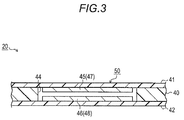
- the membrane switch 20 of the present embodiment has a known configuration in which a first film 41 and a second film 42 are laminated (bonded) with an intermediate film 40 as a spacer interposed therebetween.
- circuit patterns 47 and 48 which have contact portions 45 and 46 facing each other via a communication portion (through-hole) 44 formed in the intermediate film 40, are formed on the first film 41 and the second film 42, respectively.
- the circuit patterns 47 and 48 are formed, for example, by being printed or the like with conductive ink.
- the membrane switch 20 of the present embodiment is configured to be disposed on the inner side of the seat cushion 2, to be exact, under a cushion pad (not illustrated) provided on the inner side of the seat upholstery 2a constituting the seat occupancy surface 10, in a state in which the first film 41 is disposed on the upper side.
- the membrane switch 20 of the present embodiment the seat upholstery 2a positioned on the first film is pressed and, thereby, the first film 41 is elastically deformed in a state of being bent downward. In this manner, the contact portion 45 formed in the first film 41 comes into contact with the contact portion 46 formed in the second film 42. Then, the membrane switch 20 of the present embodiment has a configuration in which a pressure-sensitive switch unit (cell) 50 is formed of the contact portion 45 of the first film 41 and the contact portion 46 of the second film 42 which are disposed to face each other in a vertical direction.
- a pressure-sensitive switch unit (cell) 50 is formed of the contact portion 45 of the first film 41 and the contact portion 46 of the second film 42 which are disposed to face each other in a vertical direction.
- the membrane switch 20 of the present embodiment is provided under the seat upholstery 2a constituting the seat occupancy surface 10 of the seat cushion 2 and has a substantially strip-like external appearance extending in a frontward-rearward direction of the seat (rightward-leftward direction in Fig. 2 ).
- the membrane switch 20 of the present embodiment has a plurality of the pressure sensitive switch units 50 provided in a state of being arranged side by side at a substantially equal interval in a longitudinal direction of the membrane switch. Then, the membrane switch is configured to enter the ON state when at least one of the pressure sensitive switch units 50 is in an ON operation (conduction).
- the seat-occupancy state detection device 30 of the present embodiment has three rows of the membrane switches 20 provided in the state of being arranged side by side at a substantially equal interval in the width direction of the seat (vertical direction in Fig. 2 ). Specifically, the respective membrane switches 20 form separate pressure sensitive portions 60, respectively, on the seat occupancy surface 10 of the seat cushion 2.
- the seat-occupancy state detection device 30 of the present embodiment is configured to include three groups of seat occupancy sensors 21 (21 a to 21 c) having the pressure sensitive portions 60 on the inner side (inner), at the central section (center), and the outer side (outer) in the width direction of the seat, respectively, on the seat occupancy surface 10.
- an output signal of the load sensor 11 described above, which indicates the load Ws (detected value W) and ON/OFF outputs S1 to S3 of the respective seat occupancy sensors 21 are input to a seat ECU 71.
- the seat ECU 71 functions as a seat-occupancy state determination unit thereof.
- the seat ECU 71 controls an operation of a notification device such as a warning lamp, based on a result of seat-occupancy state determination thereof.
- the occupant detection determination is executed to determine whether the state is a "first seat occupancy state” indicating that an occupant sitting on the seat 1 is an adult, or a "second seat occupancy state” indicating that the occupant is a small adult such as a female adult.
- Step 101 in a state in which it is determined that the seat 1 is in the seat non-occupancy state (Step 101: YES), in a case where the seat occupancy sensor 21 enters the ON state (Step 102: YES), the seat ECU 71 determines whether or not the duration (t) is equal to or longer than a predetermined period of time t0 (Step 103) after the seat occupancy sensor enters the ON state.
- Step 102 it is determined in Step 102 that the seat occupancy sensor 21 is turned ON, on a condition that at least one of the three-system seat occupancy sensors 21 a to 21 c switches from the OFF state to the ON state.
- Step 103 in a case where it is determined that the duration is equal to or longer than the predetermined period of time t0 (t ⁇ t0 and then, Step 103: YES) after the seat occupancy sensor 21 enters the ON state, the seat ECU 71 determines whether or not the detected value W of a load detected by the load sensor 11 described above is equal to or higher than a predetermined threshold value W1 (Step 104).
- Step 104 in a case where it is determined that the detected value W of the load is equal to or higher than the predetermined threshold value W1 (W ⁇ W1 and then, Step 104: YES), the seat ECU 71 determines whether or not the detected value W of the load, which is equal to or higher than the predetermined threshold value W1, is maintained for a period of time equal to or longer than a predetermined period of time T1 (Step 105).
- Step 105 in the case where it is determined that the load (W) equal to or higher than the predetermined threshold value W1 is maintained for a period of time equal to or longer than the predetermined period of time T1 (T ⁇ T1 and then, Step 105: YES), the seat ECU 71 of the present embodiment is configured to determine that the seat 1 is in the first seat occupancy state (Step 106).
- Step 104 in a case where it is determined that the detected value W of the load is lower than the predetermined threshold value W1 (W ⁇ W1 and then, Step 104: NO), the seat ECU 71 determines whether or not the detected value W of the load detected by the load sensor 11 is equal to or higher than a predetermined threshold value W2, which is set to be lower than the predetermined threshold value W1 described above (Step 107, here, W2 ⁇ W1).
- Step 107 in the case where it is determined that the detected value W of the load is equal to or higher than the predetermined threshold value W2 (W ⁇ W2 and then, Step 107: YES), the seat ECU 71 determines whether or not the detected value W of the load, which is equal to or higher than the predetermined threshold value W2, is maintained for a period of time equal to or longer than a predetermined period of time T2 (Step 108).
- Step 108 in the case where it is determined that the detected value W of the load, which is equal to or higher than the predetermined threshold value W2, is maintained for a period of time equal to or longer than the predetermined period of time T2 (T ⁇ T2 and then, Step 108: YES), the seat ECU 71 of the present embodiment is configured to determine that the seat 1 is in the second seat occupancy state (Step 109).
- Step 102 in a case where the seat occupancy sensor 21 does not enter the ON state (Step 102: NO) and, in Step 103, the duration does not reach the predetermined period of time t0 (t ⁇ t0 and then, Step 103: NO) after the seat occupancy sensor 21 enters the ON state, the seat ECU 71 of the present embodiment does not execute the processes to Step 109.
- Step 105 in a case where a period of time, during which the detected value W of the load is maintained to be equal to or higher than the predetermined threshold value W1, does not reach the predetermined period of time T1 (T ⁇ T1 and then, Step 105: NO) and, in Step 107, the detected value W of the load is lower than the predetermined threshold value W2 (W ⁇ W2 and then, Step 107: NO), the processes to Step 109 are not executed.
- Step 108 also in a case where a period of time, during which the detected value W of the load is maintained to be equal to or higher than the predetermined threshold value W2, does not reach the predetermined period of time T2 (T ⁇ T2 and then, NO in Step 108), the process in Step 109 is not executed. Then, the seat ECU 71 of the present embodiment is configured to maintain the "previously performed determination of the seat non-occupancy state" in the states described above (Step 110).
- Step 101 in a case where it is determined that the seat 1 is in the seat occupancy state (the first seat occupancy state or the second seat occupancy state) (Step 101: NO), the seat ECU 71 does not execute the processes of the steps after Step 101. Then, in this configuration, the "previously performed determination of the seat occupancy state" is maintained.
- the seat ECU 71 of the present embodiment performs correction determination between the first seat occupancy state and the second seat occupancy state.
- the seat ECU 71 determines whether or not the detected value W of the load detected by the load sensor 11 is equal to or lower than a predetermined threshold value W3 (Step 203).
- the predetermined threshold value W3 is set to a value equal to or lower than the predetermined threshold value W2 in the seat-occupancy state determination illustrated in the flowchart in Fig. 4 described above (W3 ⁇ W2).
- Step 203 determines whether or not the detected value W of the load, which is equal to or lower than the predetermined threshold value W3, is maintained for a period of time equal to or longer than a predetermined period of time T3 (Step 204).
- Step 204 in the case where it is determined that the detected value W of the load, which is equal to or lower than the predetermined threshold value W3, is maintained for a period of time equal to or longer than the predetermined period of time T3 (T ⁇ T3 and then, Step 204: YES), the seat ECU 71 of the present embodiment is configured to determine that the seat 1 is in the second seat occupancy state (Step 205).
- the seat ECU 71 of the embodiment determines whether or not the detected value W of the load detected by the load sensor 11 is equal to or higher than a predetermined threshold value W4 (Step 206).
- the predetermined threshold value W4 is set to a value equal to or higher than the predetermined threshold value W1 in the seat-occupancy state determination illustrated in the flowchart in Fig. 4 described above (W1 ⁇ W4).
- Step 206 determines whether or not the detected value W of the load, which is equal to or higher than the predetermined threshold value W4, is maintained for a period of time equal to or longer than a predetermined period of time T4 (Step 207).
- Step 207 in the case where it is determined that the detected value W of the load, which is equal to or higher than the predetermined threshold value W4, is maintained for a period of time equal to or longer than the predetermined period of time T4 (T ⁇ T4 and then, Step 207: YES), the seat ECU 71 of the present embodiment is configured to determine that the seat 1 is in the first seat occupancy state (Step 208).
- Step 204 in a case where it is determined that a period of time, during which the detected value W of the load is maintained to be equal to or lower than the predetermined threshold value W3, does not reach the predetermined period of time T3 (T ⁇ T3 and then, Step 204: NO), the processes of the steps after Step 204 are not executed.
- the "determination to be the first seat occupancy state" is maintained in the cases described above.
- Step 207 a period of time, during which the detected value W of the load is maintained to be equal to or higher than the predetermined threshold value W4 (T ⁇ T4 and then, Step 207: NO)
- T4 the predetermined period of time
- the seat ECU 71 of the present embodiment outputs a result of the seat-occupancy state determination executed as described above as an external output signal Ex to an airbag ECU 72 and another external device.
- inflation control of an airbag (not illustrated) is executed, based on the result of the seat-occupancy state determination by the seat ECU 71.
- the airbag ECU 72 in a case where the external output signal Ex of the seat ECU 71 indicates that the seat 1 is in the seat occupancy state (Step 301: YES), the airbag ECU 72 first causes an indicator (not illustrated), which indicates that the airbag can be inflated, to be turned ON (Step 302). Next, the airbag ECU 72 determines whether or not the seat occupancy state of the seat 1 is the first seat occupancy state (Step 303).
- a control mode of the airbag is set to a first inflation mode having a predetermined inflation force (inflation force: strong, in Step 304).
- the airbag ECU 72 sets the control mode of the airbag to a second inflation mode having a weaker force than in the first inflation mode described above (Step 305).
- the airbag ECU 72 causes the indicator of the airbag to be turned OFF (Step 306).
- the control mode of the airbag is set to a non-inflation mode in which inflation of the airbag is not performed (Step 307).
- the seat ECU 71 of the present embodiment executes transition determination to the seat non-occupancy state, based on a comparison between the detected value W and the threshold value of the load.
- the seat ECU 71 of the present embodiment executes the transition determination from the seat occupancy state to the seat non-occupancy state (seat non-occupancy determination), based on whether or not the detected value W of the load detected by the load sensor 11, to be exact, an absolute value, is equal to or lower than the threshold value. Further, in the seat-occupancy state detection device 30 of the present embodiment, it is determined in Step 402 that the seat occupancy sensor 21 is turned OFF, on a condition that all of the three groups of seat occupancy sensors 21 a to 21 c, which form the pressure sensitive portions 60 at different positions on the seat occupancy surface 10, enter the OFF state.
- the seat ECU 71 of the present embodiment monitors the duration after the seat occupancy sensors 21 enter the OFF state (Steps 403, 404, and 406).
- a threshold value (third threshold value) of the load used in the seat non-occupancy determination is set to a higher value (W5 ⁇ W6 ⁇ W7), as the duration increases (t1 ⁇ t2 ⁇ t3) after the seat occupancy sensors 21 enter the OFF state (Steps 405, 407, and 408).
- Step 406 the duration is equal to or longer than the predetermined period of time t3 (t ⁇ t3 and then, Step 406: YES) after the seat occupancy sensors 21 enter the OFF state
- the seat ECU 71 of the present embodiment sets the threshold value of the load used in the seat non-occupancy determination to "W7". Then, it is determined that the detected value W of the load detected by the load sensor 11 is equal to or lower than the threshold value W7 (Step 408).
- the seat ECU 71 of the present embodiment determines whether or not the detected value W of the load, which is equal to or lower than the threshold value W5, is maintained to be equal to or longer than a predetermined period of time T5 (Step 409).
- the seat ECU determines, in Step 409, whether or not the detected value W of the load, which is equal to or lower than the threshold value W6, is maintained to be equal to or longer than the predetermined period of time T5.
- the seat ECU determines, in Step 409, whether or not the detected value W of the load, which is equal to or lower than the threshold value W7, is maintained to be equal to or longer than the predetermined period of time T5.
- the detected value W (absolute value) of the load detected by the load sensor 11 becomes a value indicating an unloaded state
- the detected value W of the load tends to significantly change by rocking of the seat cushion 2 based on the occupant's behavioral posture
- the seat occupancy sensors 21 also temporarily enter the OFF state due to the change in the occupant's behavioral posture, in some cases. Therefore, immediately after the seat occupancy sensors 21 enter the OFF state, it is difficult to distinguish the occupant's behavioral posture from the seat non-occupancy behavior to a temporary change in posture and, thereby, confirmation of the seat non-occupancy determination can be delayed.
- the seat ECU 71 of the present embodiment monitors the duration (t) after the seat occupancy sensors 21 enter the OFF state and, thereby, the seat non-occupancy behavioral posture of the occupant who sits on the seat 1 and reliability of the seat non-occupancy behavioral posture are assumed.
- the occupant's behavioral posture, from which transition to the OFF state of the seat occupancy sensors 21 ensues actually means leaving the seat 1 as the duration increases after the seat occupancy sensors 21 enter the OFF state.
- the seat ECU 71 of the present embodiment is configured to set the threshold value of the load used in the seat non-occupancy determination to a higher value, as the reliability of the seat non-occupancy behavior assumed by the duration increases after the seat occupancy sensors 21 enter the OFF state.
- the seat ECU 71 of the present embodiment sets the threshold value of the load used in the seat non-occupancy determination to the lowest "W5" in first seat non-occupancy assumption discrimination in which the duration is maintained for the predetermined period of time t1 to the predetermined period of time t2 after the seat occupancy sensors 21 enter the OFF state.
- the threshold value of the load used in the seat non-occupancy determination is set to "W6" higher than the threshold value W5 in the first seat non-occupancy assumption discrimination.
- the threshold value of the load used in the seat non-occupancy determination is set to the highest "W7". Accordingly, determination conditions according to the load Ws (W) are relaxed in a stepwise manner, based on the duration after the seat occupancy sensors 21 enter the OFF state and, thereby, the seat ECU 71 of the present embodiment can more rapidly perform the seat non-occupancy determination without lowering the determination accuracy.
- an applied position of the load Ws by the occupant sitting on the seat 1 is changed depending on the occupant's seat occupancy posture.
- the applied position of the load Ws is shifted in a tilting direction of the seat occupancy posture. In this manner, an error in the detected value W of the load detected by the load sensor 11 can be made.
- the seat ECU 71 of the present embodiment corrects the threshold values W1 to W4 of the load used in the occupant detection determination such that threshold values W1' to W4' obtained after the correction are higher values, as the applied position of the load Ws, which is specified from the tilting discrimination of the seat occupancy posture, is closer to the position at which the load sensor 11 is disposed. In this manner, the seat ECU 71 of the present embodiment can perform the occupant detection determination with high accuracy.
- the seat ECU 71 of the present embodiment assumes a "central seat-occupancy posture" in which the occupant's seat occupancy posture does not tilt on the seat 1. Then, even in a case where only the seat occupancy sensor 21 b having the pressure sensitive portion 60 at the central position in the width direction of the seat enters the ON state, it is assumed that the occupant's seat occupancy posture is the "central seat-occupancy posture".
- the seat ECU 71 assumes "first outer-tilting seat-occupancy posture" in which the occupant's seat occupancy posture tilts to the outer side. Then, in a case where only the seat occupancy sensor 21a on the inner side in the width direction of the seat enters the ON state, it is assumed that the occupant's seat occupancy posture is "second inner-tilting seat occupancy posture” in which the occupant's seat occupancy posture further tilts to the inner side in the width direction of the seat.
- the occupant's seat occupancy posture is "second outer-tilting seat occupancy posture" in which the occupant's seat occupancy posture further tilts to the outer side in the width direction of the seat.
- the seat ECU 71 of the present embodiment is configured not to perform correction of the threshold values W1 to W4 of the load used in the occupant detection determination.
- the seat ECU 71 of the present embodiment performs adding correction to the threshold values W1 to W4 of the load used in the occupant detection determination such that the corrected threshold values W1' to W4' are increased to be higher values, as the assumed seat occupancy posture has a greater tilt to the inner side in the width direction of the seat, in the tilting discrimination, on the basis of the case where the occupant's seat occupancy posture does not tilt.
- the seat ECU performs subtracting correction to the threshold values W1 to W4 of the load used in the occupant detection determination such that the corrected threshold values W1' to W4' are decreased to be lower values, as the assumed seat occupancy posture has a greater tilt to the outer side in the width direction of the seat, in the tilting discrimination. Then, the seat ECU 71 of the present embodiment determines the physique of the occupant using the corrected threshold values W1' to W4', thereby making it possible to perform the occupant detection determination with high accuracy.
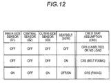
- the seat ECU 71 of the present embodiment monitors the detected value W of the load detected by the load sensor 11 in a case where all of the three groups of seat occupancy sensors 21 a to 21 c, which form the pressure sensitive portions 60 at different positions on the seat occupancy surface 10, enter the ON state (refer to Fig. 9 , the central seat-occupancy posture).
- the detected value W (absolute value) of the load is equal to or lower than a predetermined threshold value W8 (first threshold value) that indicates the unloaded state, it is determined that an "abnormality" (first abnormality), in which the ON state of the seat occupancy sensors 21 a to 21 c is maintained without switching between the ON/OFF states, occurs.
- the cushion pad is disposed on the inner side of the seat cushion 2, on which the membrane switches 20 constituting the seat occupancy sensors 21 a to 21 c are arranged.
- the cushion material for example, a forming resin material
- the cushion pad often tends to be subjected to thermal expansion. Therefore, in a high-temperature environment, the seat occupancy sensor is pressed by the expanded cushion pad, and thereby there is a possibility that the seat occupancy sensors 21 a to 21 c remain in the ON state.
- the seat ECU 71 of the present embodiment performs abnormality determination based on a comparison between the threshold value and the detected value W of the load sensor 11 and the ON/OFF combination of the seat occupancy sensors 21a to 21 c as described above. In this manner, it is possible to rapidly detect the abnormality in which the ON state of the seat occupancy sensors 21 a to 21 c is maintained without switching between the ON/OFF states.
- the seat ECU 71 of the present embodiment monitors the detected value W of the load detected by the load sensor 11 even in a case where all of the seat occupancy sensors 21 a to 21 c enter the OFF state.
- the detected value W of the load is equal to or higher than the threshold value W1 used in the determination of the first seat occupancy state, that is, a value corresponding to the case where an "adult" sits on the seat 1, it is determined that an abnormality occurs in any one of the seat occupancy sensors 21 a to 21 c or the load sensor 11.
- the seat ECU 71 determines whether or not all of the three groups of seat occupancy sensors 21a to 21c, which form the pressure sensitive portions 60 at different positions on the seat occupancy surface 10, enter the OFF state (Step 501). Further, the seat ECU 71 determines, in the case where all of the three groups of seat occupancy sensors 21 enter the OFF state (Step 501: YES), whether or not the detected value W (absolute value) of the load detected by the load sensor 11 is equal to or lower than the predetermined threshold value W8 indicating the unloaded state (Step 502).
- the seat ECU 71 of the present embodiment stores the zero point W0 of the load, together with the threshold values (W1 to W8, t0 to t3, and T1 to T5) of the load used in the seat-occupancy state determination described above, and the correction values ( ⁇ 1 and ⁇ 2), in a storage area 71 a (refer to Fig. 1 ).
- the detected value W of the load detected by the load sensor 11 becomes a value with the zero point W0 as a reference ( ⁇ 0).
- the seat ECU 71 of the present embodiment performs the zero-point correction by updating a value of the zero point W0 stored in the storage area 71 a to the detected value W of the load at the time of correction.
- the seat-occupancy state detection device includes the seat non-occupancy state determination section that determines a seat non-occupancy state in which no occupant sits on the seat in a case where the seat occupancy sensor enters the OFF state and the load is equal to or lower than the threshold value, and the threshold-value setting section that sets the threshold value of the load used in determination of the seat non-occupancy state to a higher value, as a duration increases after the seat occupancy sensor enters the OFF state.
Applications Claiming Priority (1)
| Application Number | Priority Date | Filing Date | Title |
|---|---|---|---|
| JP2015123947A JP6536206B2 (ja) | 2015-06-19 | 2015-06-19 | 着座状態検知装置 |
Publications (2)
| Publication Number | Publication Date |
|---|---|
| EP3124318A1 true EP3124318A1 (de) | 2017-02-01 |
| EP3124318B1 EP3124318B1 (de) | 2017-11-15 |
Family
ID=56551119
Family Applications (1)
| Application Number | Title | Priority Date | Filing Date |
|---|---|---|---|
| EP16175037.7A Active EP3124318B1 (de) | 2015-06-19 | 2016-06-17 | Sitzplatzbelegungsstatusdetektionsvorrichtung |
Country Status (3)
| Country | Link |
|---|---|
| US (1) | US20160371899A1 (de) |
| EP (1) | EP3124318B1 (de) |
| JP (1) | JP6536206B2 (de) |
Families Citing this family (3)
| Publication number | Priority date | Publication date | Assignee | Title |
|---|---|---|---|---|
| JP6772786B2 (ja) * | 2016-11-25 | 2020-10-21 | アイシン精機株式会社 | 乗員検知装置および乗員検知プログラム |
| ES2678748B2 (es) * | 2017-02-15 | 2019-02-18 | Univ De Las Palmas De Gran Canaria | Sistema electrónico para estimación de carga y centrado de aeronaves |
| CN113271819A (zh) * | 2019-01-04 | 2021-08-17 | 株式会社藤仓 | 就座传感器及座席装置 |
Citations (5)
| Publication number | Priority date | Publication date | Assignee | Title |
|---|---|---|---|---|
| JP2000301980A (ja) * | 1999-04-20 | 2000-10-31 | Furukawa Electric Co Ltd:The | 乗員検出装置 |
| DE10152958A1 (de) * | 2001-10-26 | 2003-08-21 | Hottinger Messtechnik Baldwin | Vorrichtung und Verfahren zur sitzbelegungsabhängigen Ansteuerung von Sicherheitssystemen |
| EP1577170A1 (de) * | 2004-03-18 | 2005-09-21 | Delphi Technologies, Inc. | Verfahren zur Feststellung und Anzeige eines Airbag-Unterdrückungs Zustandes |
| DE102007062764A1 (de) * | 2007-06-14 | 2008-12-18 | Kia Motors Corporation | System und Verfahren zum Klassifizieren von Fahrzeuginsassen |
| JP2010195358A (ja) | 2009-02-27 | 2010-09-09 | Aisin Seiki Co Ltd | 乗員検知センサ及び乗員検知システム |
Family Cites Families (4)
| Publication number | Priority date | Publication date | Assignee | Title |
|---|---|---|---|---|
| JP3753083B2 (ja) * | 2001-06-27 | 2006-03-08 | 株式会社デンソー | 着席状態検知装置 |
| JP4474995B2 (ja) * | 2004-04-28 | 2010-06-09 | 株式会社デンソー | 車両用着座センサ |
| JP2006266706A (ja) * | 2005-03-22 | 2006-10-05 | Aisin Seiki Co Ltd | 荷重検出装置 |
| JP4881089B2 (ja) * | 2006-07-13 | 2012-02-22 | カルソニックカンセイ株式会社 | 車両用乗員検知装置 |
-
2015
- 2015-06-19 JP JP2015123947A patent/JP6536206B2/ja active Active
-
2016
- 2016-06-16 US US15/183,962 patent/US20160371899A1/en not_active Abandoned
- 2016-06-17 EP EP16175037.7A patent/EP3124318B1/de active Active
Patent Citations (5)
| Publication number | Priority date | Publication date | Assignee | Title |
|---|---|---|---|---|
| JP2000301980A (ja) * | 1999-04-20 | 2000-10-31 | Furukawa Electric Co Ltd:The | 乗員検出装置 |
| DE10152958A1 (de) * | 2001-10-26 | 2003-08-21 | Hottinger Messtechnik Baldwin | Vorrichtung und Verfahren zur sitzbelegungsabhängigen Ansteuerung von Sicherheitssystemen |
| EP1577170A1 (de) * | 2004-03-18 | 2005-09-21 | Delphi Technologies, Inc. | Verfahren zur Feststellung und Anzeige eines Airbag-Unterdrückungs Zustandes |
| DE102007062764A1 (de) * | 2007-06-14 | 2008-12-18 | Kia Motors Corporation | System und Verfahren zum Klassifizieren von Fahrzeuginsassen |
| JP2010195358A (ja) | 2009-02-27 | 2010-09-09 | Aisin Seiki Co Ltd | 乗員検知センサ及び乗員検知システム |
Also Published As
| Publication number | Publication date |
|---|---|
| JP6536206B2 (ja) | 2019-07-03 |
| JP2017007472A (ja) | 2017-01-12 |
| EP3124318B1 (de) | 2017-11-15 |
| US20160371899A1 (en) | 2016-12-22 |
Similar Documents
| Publication | Publication Date | Title |
|---|---|---|
| EP3106355B1 (de) | Sitzplatzbelegungsstatusdetektionsvorrichtung | |
| US6490515B1 (en) | Passenger detecting apparatus | |
| US7791462B2 (en) | Occupant detecting apparatus | |
| EP3124318B1 (de) | Sitzplatzbelegungsstatusdetektionsvorrichtung | |
| JP4434259B2 (ja) | 着座センサ | |
| JP5515460B2 (ja) | 着座判定装置および着座判定方法 | |
| EP2329998B1 (de) | Vorrichtung zur Sitzbelegungserkennung | |
| JP2008132928A (ja) | 着座センサ | |
| US9329075B2 (en) | Seat occupancy determination device and seat occupancy determination method | |
| US6876299B2 (en) | Occupant determining device | |
| US7859422B2 (en) | Seat sensor | |
| US20170232868A1 (en) | Occupant detection method and occupant detection apparatus | |
| JP3753083B2 (ja) | 着席状態検知装置 | |
| CN107791892B (zh) | 乘员检测装置 | |
| JP5499491B2 (ja) | 乗員検知センサ及び乗員検知システム | |
| KR20180083573A (ko) | 후석 센터의 승객 감지를 위한 sbr mat 센서 | |
| JP6744570B2 (ja) | 着座検知装置 | |
| US20100170722A1 (en) | Load detecting device, seat, and load sensor | |
| US11268847B2 (en) | Seat load detection method and seat load detection apparatus | |
| JP6448088B2 (ja) | 車両用乗員判定装置 | |
| JP2005212496A (ja) | 乗員検知装置 | |
| JP2014193704A (ja) | 荷重センサを用いる乗員判定装置 | |
| JP4337043B2 (ja) | 乗員検知システム | |
| JP6405884B2 (ja) | 車両シートの挟み込み検知装置 | |
| JP2005271763A (ja) | 乗員検知装置 |
Legal Events
| Date | Code | Title | Description |
|---|---|---|---|
| PUAI | Public reference made under article 153(3) epc to a published international application that has entered the european phase |
Free format text: ORIGINAL CODE: 0009012 |
|
| AK | Designated contracting states |
Kind code of ref document: A1 Designated state(s): AL AT BE BG CH CY CZ DE DK EE ES FI FR GB GR HR HU IE IS IT LI LT LU LV MC MK MT NL NO PL PT RO RS SE SI SK SM TR |
|
| AX | Request for extension of the european patent |
Extension state: BA ME |
|
| 17P | Request for examination filed |
Effective date: 20170307 |
|
| RBV | Designated contracting states (corrected) |
Designated state(s): AL AT BE BG CH CY CZ DE DK EE ES FI FR GB GR HR HU IE IS IT LI LT LU LV MC MK MT NL NO PL PT RO RS SE SI SK SM TR |
|
| REG | Reference to a national code |
Ref country code: DE Ref legal event code: R079 Ref document number: 602016000818 Country of ref document: DE Free format text: PREVIOUS MAIN CLASS: B60N0002000000 Ipc: B60R0021010000 |
|
| RIC1 | Information provided on ipc code assigned before grant |
Ipc: G07C 5/08 20060101ALI20170427BHEP Ipc: G01G 19/414 20060101ALI20170427BHEP Ipc: B60N 2/00 20060101ALI20170427BHEP Ipc: B60R 21/01 20060101AFI20170427BHEP Ipc: B60R 21/015 20060101ALI20170427BHEP |
|
| GRAP | Despatch of communication of intention to grant a patent |
Free format text: ORIGINAL CODE: EPIDOSNIGR1 |
|
| INTG | Intention to grant announced |
Effective date: 20170609 |
|
| GRAS | Grant fee paid |
Free format text: ORIGINAL CODE: EPIDOSNIGR3 |
|
| GRAA | (expected) grant |
Free format text: ORIGINAL CODE: 0009210 |
|
| AK | Designated contracting states |
Kind code of ref document: B1 Designated state(s): AL AT BE BG CH CY CZ DE DK EE ES FI FR GB GR HR HU IE IS IT LI LT LU LV MC MK MT NL NO PL PT RO RS SE SI SK SM TR |
|
| REG | Reference to a national code |
Ref country code: CH Ref legal event code: EP Ref country code: GB Ref legal event code: FG4D Ref country code: AT Ref legal event code: REF Ref document number: 945927 Country of ref document: AT Kind code of ref document: T Effective date: 20171115 |
|
| REG | Reference to a national code |
Ref country code: IE Ref legal event code: FG4D |
|
| REG | Reference to a national code |
Ref country code: DE Ref legal event code: R096 Ref document number: 602016000818 Country of ref document: DE |
|
| REG | Reference to a national code |
Ref country code: NL Ref legal event code: MP Effective date: 20171115 |
|
| REG | Reference to a national code |
Ref country code: LT Ref legal event code: MG4D |
|
| REG | Reference to a national code |
Ref country code: AT Ref legal event code: MK05 Ref document number: 945927 Country of ref document: AT Kind code of ref document: T Effective date: 20171115 |
|
| PG25 | Lapsed in a contracting state [announced via postgrant information from national office to epo] |
Ref country code: ES Free format text: LAPSE BECAUSE OF FAILURE TO SUBMIT A TRANSLATION OF THE DESCRIPTION OR TO PAY THE FEE WITHIN THE PRESCRIBED TIME-LIMIT Effective date: 20171115 Ref country code: NO Free format text: LAPSE BECAUSE OF FAILURE TO SUBMIT A TRANSLATION OF THE DESCRIPTION OR TO PAY THE FEE WITHIN THE PRESCRIBED TIME-LIMIT Effective date: 20180215 Ref country code: SE Free format text: LAPSE BECAUSE OF FAILURE TO SUBMIT A TRANSLATION OF THE DESCRIPTION OR TO PAY THE FEE WITHIN THE PRESCRIBED TIME-LIMIT Effective date: 20171115 Ref country code: NL Free format text: LAPSE BECAUSE OF FAILURE TO SUBMIT A TRANSLATION OF THE DESCRIPTION OR TO PAY THE FEE WITHIN THE PRESCRIBED TIME-LIMIT Effective date: 20171115 Ref country code: FI Free format text: LAPSE BECAUSE OF FAILURE TO SUBMIT A TRANSLATION OF THE DESCRIPTION OR TO PAY THE FEE WITHIN THE PRESCRIBED TIME-LIMIT Effective date: 20171115 Ref country code: LT Free format text: LAPSE BECAUSE OF FAILURE TO SUBMIT A TRANSLATION OF THE DESCRIPTION OR TO PAY THE FEE WITHIN THE PRESCRIBED TIME-LIMIT Effective date: 20171115 |
|
| REG | Reference to a national code |
Ref country code: FR Ref legal event code: PLFP Year of fee payment: 3 |
|
| PG25 | Lapsed in a contracting state [announced via postgrant information from national office to epo] |
Ref country code: GR Free format text: LAPSE BECAUSE OF FAILURE TO SUBMIT A TRANSLATION OF THE DESCRIPTION OR TO PAY THE FEE WITHIN THE PRESCRIBED TIME-LIMIT Effective date: 20180216 Ref country code: BG Free format text: LAPSE BECAUSE OF FAILURE TO SUBMIT A TRANSLATION OF THE DESCRIPTION OR TO PAY THE FEE WITHIN THE PRESCRIBED TIME-LIMIT Effective date: 20180215 Ref country code: HR Free format text: LAPSE BECAUSE OF FAILURE TO SUBMIT A TRANSLATION OF THE DESCRIPTION OR TO PAY THE FEE WITHIN THE PRESCRIBED TIME-LIMIT Effective date: 20171115 Ref country code: RS Free format text: LAPSE BECAUSE OF FAILURE TO SUBMIT A TRANSLATION OF THE DESCRIPTION OR TO PAY THE FEE WITHIN THE PRESCRIBED TIME-LIMIT Effective date: 20171115 Ref country code: LV Free format text: LAPSE BECAUSE OF FAILURE TO SUBMIT A TRANSLATION OF THE DESCRIPTION OR TO PAY THE FEE WITHIN THE PRESCRIBED TIME-LIMIT Effective date: 20171115 Ref country code: AT Free format text: LAPSE BECAUSE OF FAILURE TO SUBMIT A TRANSLATION OF THE DESCRIPTION OR TO PAY THE FEE WITHIN THE PRESCRIBED TIME-LIMIT Effective date: 20171115 |
|
| PG25 | Lapsed in a contracting state [announced via postgrant information from national office to epo] |
Ref country code: SK Free format text: LAPSE BECAUSE OF FAILURE TO SUBMIT A TRANSLATION OF THE DESCRIPTION OR TO PAY THE FEE WITHIN THE PRESCRIBED TIME-LIMIT Effective date: 20171115 Ref country code: CZ Free format text: LAPSE BECAUSE OF FAILURE TO SUBMIT A TRANSLATION OF THE DESCRIPTION OR TO PAY THE FEE WITHIN THE PRESCRIBED TIME-LIMIT Effective date: 20171115 Ref country code: DK Free format text: LAPSE BECAUSE OF FAILURE TO SUBMIT A TRANSLATION OF THE DESCRIPTION OR TO PAY THE FEE WITHIN THE PRESCRIBED TIME-LIMIT Effective date: 20171115 Ref country code: CY Free format text: LAPSE BECAUSE OF FAILURE TO SUBMIT A TRANSLATION OF THE DESCRIPTION OR TO PAY THE FEE WITHIN THE PRESCRIBED TIME-LIMIT Effective date: 20171115 Ref country code: EE Free format text: LAPSE BECAUSE OF FAILURE TO SUBMIT A TRANSLATION OF THE DESCRIPTION OR TO PAY THE FEE WITHIN THE PRESCRIBED TIME-LIMIT Effective date: 20171115 |
|
| REG | Reference to a national code |
Ref country code: DE Ref legal event code: R097 Ref document number: 602016000818 Country of ref document: DE |
|
| PG25 | Lapsed in a contracting state [announced via postgrant information from national office to epo] |
Ref country code: PL Free format text: LAPSE BECAUSE OF FAILURE TO SUBMIT A TRANSLATION OF THE DESCRIPTION OR TO PAY THE FEE WITHIN THE PRESCRIBED TIME-LIMIT Effective date: 20171115 Ref country code: IT Free format text: LAPSE BECAUSE OF FAILURE TO SUBMIT A TRANSLATION OF THE DESCRIPTION OR TO PAY THE FEE WITHIN THE PRESCRIBED TIME-LIMIT Effective date: 20171115 Ref country code: SM Free format text: LAPSE BECAUSE OF FAILURE TO SUBMIT A TRANSLATION OF THE DESCRIPTION OR TO PAY THE FEE WITHIN THE PRESCRIBED TIME-LIMIT Effective date: 20171115 |
|
| PLBE | No opposition filed within time limit |
Free format text: ORIGINAL CODE: 0009261 |
|
| STAA | Information on the status of an ep patent application or granted ep patent |
Free format text: STATUS: NO OPPOSITION FILED WITHIN TIME LIMIT |
|
| 26N | No opposition filed |
Effective date: 20180817 |
|
| REG | Reference to a national code |
Ref country code: BE Ref legal event code: MM Effective date: 20180630 |
|
| REG | Reference to a national code |
Ref country code: IE Ref legal event code: MM4A |
|
| PG25 | Lapsed in a contracting state [announced via postgrant information from national office to epo] |
Ref country code: LU Free format text: LAPSE BECAUSE OF NON-PAYMENT OF DUE FEES Effective date: 20180617 Ref country code: MC Free format text: LAPSE BECAUSE OF FAILURE TO SUBMIT A TRANSLATION OF THE DESCRIPTION OR TO PAY THE FEE WITHIN THE PRESCRIBED TIME-LIMIT Effective date: 20171115 |
|
| PG25 | Lapsed in a contracting state [announced via postgrant information from national office to epo] |
Ref country code: IE Free format text: LAPSE BECAUSE OF NON-PAYMENT OF DUE FEES Effective date: 20180617 |
|
| PG25 | Lapsed in a contracting state [announced via postgrant information from national office to epo] |
Ref country code: BE Free format text: LAPSE BECAUSE OF NON-PAYMENT OF DUE FEES Effective date: 20180630 |
|
| PG25 | Lapsed in a contracting state [announced via postgrant information from national office to epo] |
Ref country code: MT Free format text: LAPSE BECAUSE OF NON-PAYMENT OF DUE FEES Effective date: 20180617 |
|
| REG | Reference to a national code |
Ref country code: CH Ref legal event code: PL |
|
| PG25 | Lapsed in a contracting state [announced via postgrant information from national office to epo] |
Ref country code: TR Free format text: LAPSE BECAUSE OF FAILURE TO SUBMIT A TRANSLATION OF THE DESCRIPTION OR TO PAY THE FEE WITHIN THE PRESCRIBED TIME-LIMIT Effective date: 20171115 |
|
| PG25 | Lapsed in a contracting state [announced via postgrant information from national office to epo] |
Ref country code: PT Free format text: LAPSE BECAUSE OF FAILURE TO SUBMIT A TRANSLATION OF THE DESCRIPTION OR TO PAY THE FEE WITHIN THE PRESCRIBED TIME-LIMIT Effective date: 20171115 Ref country code: LI Free format text: LAPSE BECAUSE OF NON-PAYMENT OF DUE FEES Effective date: 20190630 Ref country code: CH Free format text: LAPSE BECAUSE OF NON-PAYMENT OF DUE FEES Effective date: 20190630 |
|
| PG25 | Lapsed in a contracting state [announced via postgrant information from national office to epo] |
Ref country code: RO Free format text: LAPSE BECAUSE OF FAILURE TO SUBMIT A TRANSLATION OF THE DESCRIPTION OR TO PAY THE FEE WITHIN THE PRESCRIBED TIME-LIMIT Effective date: 20171115 Ref country code: HU Free format text: LAPSE BECAUSE OF FAILURE TO SUBMIT A TRANSLATION OF THE DESCRIPTION OR TO PAY THE FEE WITHIN THE PRESCRIBED TIME-LIMIT; INVALID AB INITIO Effective date: 20160617 Ref country code: MK Free format text: LAPSE BECAUSE OF NON-PAYMENT OF DUE FEES Effective date: 20171115 |
|
| PG25 | Lapsed in a contracting state [announced via postgrant information from national office to epo] |
Ref country code: AL Free format text: LAPSE BECAUSE OF FAILURE TO SUBMIT A TRANSLATION OF THE DESCRIPTION OR TO PAY THE FEE WITHIN THE PRESCRIBED TIME-LIMIT Effective date: 20171115 Ref country code: IS Free format text: LAPSE BECAUSE OF FAILURE TO SUBMIT A TRANSLATION OF THE DESCRIPTION OR TO PAY THE FEE WITHIN THE PRESCRIBED TIME-LIMIT Effective date: 20180315 |
|
| PG25 | Lapsed in a contracting state [announced via postgrant information from national office to epo] |
Ref country code: SI Free format text: LAPSE BECAUSE OF NON-PAYMENT OF DUE FEES Effective date: 20180617 |
|
| GBPC | Gb: european patent ceased through non-payment of renewal fee |
Effective date: 20200617 |
|
| PG25 | Lapsed in a contracting state [announced via postgrant information from national office to epo] |
Ref country code: GB Free format text: LAPSE BECAUSE OF NON-PAYMENT OF DUE FEES Effective date: 20200617 |
|
| PGFP | Annual fee paid to national office [announced via postgrant information from national office to epo] |
Ref country code: FR Payment date: 20230510 Year of fee payment: 8 Ref country code: DE Payment date: 20230502 Year of fee payment: 8 |