EP3124251A1 - Flüssigkeitsausstosskopf und aufzeichnungsvorrichtung - Google Patents
Flüssigkeitsausstosskopf und aufzeichnungsvorrichtung Download PDFInfo
- Publication number
- EP3124251A1 EP3124251A1 EP15769121.3A EP15769121A EP3124251A1 EP 3124251 A1 EP3124251 A1 EP 3124251A1 EP 15769121 A EP15769121 A EP 15769121A EP 3124251 A1 EP3124251 A1 EP 3124251A1
- Authority
- EP
- European Patent Office
- Prior art keywords
- flow passage
- liquid
- pressurizing chamber
- discharge head
- pressurizing
- Prior art date
- Legal status (The legal status is an assumption and is not a legal conclusion. Google has not performed a legal analysis and makes no representation as to the accuracy of the status listed.)
- Granted
Links
- 239000007788 liquid Substances 0.000 title claims abstract description 243
- 230000005484 gravity Effects 0.000 claims description 10
- 238000007599 discharging Methods 0.000 claims description 3
- 239000000758 substrate Substances 0.000 description 16
- 239000000919 ceramic Substances 0.000 description 11
- 238000006073 displacement reaction Methods 0.000 description 10
- 230000004048 modification Effects 0.000 description 9
- 238000012986 modification Methods 0.000 description 9
- 239000000463 material Substances 0.000 description 7
- 230000008054 signal transmission Effects 0.000 description 7
- 239000000976 ink Substances 0.000 description 5
- 239000002184 metal Substances 0.000 description 4
- 229910052751 metal Inorganic materials 0.000 description 4
- 239000000049 pigment Substances 0.000 description 4
- 239000000956 alloy Substances 0.000 description 3
- 229910045601 alloy Inorganic materials 0.000 description 3
- 238000000605 extraction Methods 0.000 description 3
- 239000011347 resin Substances 0.000 description 3
- 229920005989 resin Polymers 0.000 description 3
- 239000000853 adhesive Substances 0.000 description 2
- 230000001070 adhesive effect Effects 0.000 description 2
- 239000013043 chemical agent Substances 0.000 description 2
- 239000003086 colorant Substances 0.000 description 2
- 239000004744 fabric Substances 0.000 description 2
- 238000010438 heat treatment Methods 0.000 description 2
- 238000009413 insulation Methods 0.000 description 2
- 229910052451 lead zirconate titanate Inorganic materials 0.000 description 2
- 239000007769 metal material Substances 0.000 description 2
- 238000000034 method Methods 0.000 description 2
- 229910003378 NaNbO3 Inorganic materials 0.000 description 1
- 229910002113 barium titanate Inorganic materials 0.000 description 1
- 229910010293 ceramic material Inorganic materials 0.000 description 1
- 238000006243 chemical reaction Methods 0.000 description 1
- 239000011248 coating agent Substances 0.000 description 1
- 230000007423 decrease Effects 0.000 description 1
- 230000000694 effects Effects 0.000 description 1
- 230000005621 ferroelectricity Effects 0.000 description 1
- 239000011521 glass Substances 0.000 description 1
- -1 glass frit Chemical compound 0.000 description 1
- 238000010030 laminating Methods 0.000 description 1
- HFGPZNIAWCZYJU-UHFFFAOYSA-N lead zirconate titanate Chemical compound [O-2].[O-2].[O-2].[O-2].[O-2].[Ti+4].[Zr+4].[Pb+2] HFGPZNIAWCZYJU-UHFFFAOYSA-N 0.000 description 1
- 238000004519 manufacturing process Methods 0.000 description 1
- 239000011159 matrix material Substances 0.000 description 1
- KDLHZDBZIXYQEI-UHFFFAOYSA-N palladium Substances [Pd] KDLHZDBZIXYQEI-UHFFFAOYSA-N 0.000 description 1
- SWELZOZIOHGSPA-UHFFFAOYSA-N palladium silver Chemical compound [Pd].[Ag] SWELZOZIOHGSPA-UHFFFAOYSA-N 0.000 description 1
- 239000002245 particle Substances 0.000 description 1
- 230000000717 retained effect Effects 0.000 description 1
- MUPJWXCPTRQOKY-UHFFFAOYSA-N sodium;niobium(5+);oxygen(2-) Chemical compound [O-2].[O-2].[O-2].[Na+].[Nb+5] MUPJWXCPTRQOKY-UHFFFAOYSA-N 0.000 description 1
- 239000000126 substance Substances 0.000 description 1
- 238000004381 surface treatment Methods 0.000 description 1
Images


Classifications
-
- B—PERFORMING OPERATIONS; TRANSPORTING
- B41—PRINTING; LINING MACHINES; TYPEWRITERS; STAMPS
- B41J—TYPEWRITERS; SELECTIVE PRINTING MECHANISMS, i.e. MECHANISMS PRINTING OTHERWISE THAN FROM A FORME; CORRECTION OF TYPOGRAPHICAL ERRORS
- B41J2/00—Typewriters or selective printing mechanisms characterised by the printing or marking process for which they are designed
- B41J2/005—Typewriters or selective printing mechanisms characterised by the printing or marking process for which they are designed characterised by bringing liquid or particles selectively into contact with a printing material
- B41J2/01—Ink jet
- B41J2/135—Nozzles
- B41J2/14—Structure thereof only for on-demand ink jet heads
- B41J2/14201—Structure of print heads with piezoelectric elements
- B41J2/14233—Structure of print heads with piezoelectric elements of film type, deformed by bending and disposed on a diaphragm
-
- B—PERFORMING OPERATIONS; TRANSPORTING
- B41—PRINTING; LINING MACHINES; TYPEWRITERS; STAMPS
- B41J—TYPEWRITERS; SELECTIVE PRINTING MECHANISMS, i.e. MECHANISMS PRINTING OTHERWISE THAN FROM A FORME; CORRECTION OF TYPOGRAPHICAL ERRORS
- B41J2/00—Typewriters or selective printing mechanisms characterised by the printing or marking process for which they are designed
- B41J2/005—Typewriters or selective printing mechanisms characterised by the printing or marking process for which they are designed characterised by bringing liquid or particles selectively into contact with a printing material
- B41J2/01—Ink jet
- B41J2/135—Nozzles
- B41J2/14—Structure thereof only for on-demand ink jet heads
- B41J2/14201—Structure of print heads with piezoelectric elements
- B41J2/14209—Structure of print heads with piezoelectric elements of finger type, chamber walls consisting integrally of piezoelectric material
-
- B—PERFORMING OPERATIONS; TRANSPORTING
- B41—PRINTING; LINING MACHINES; TYPEWRITERS; STAMPS
- B41J—TYPEWRITERS; SELECTIVE PRINTING MECHANISMS, i.e. MECHANISMS PRINTING OTHERWISE THAN FROM A FORME; CORRECTION OF TYPOGRAPHICAL ERRORS
- B41J2/00—Typewriters or selective printing mechanisms characterised by the printing or marking process for which they are designed
- B41J2/005—Typewriters or selective printing mechanisms characterised by the printing or marking process for which they are designed characterised by bringing liquid or particles selectively into contact with a printing material
- B41J2/01—Ink jet
- B41J2/135—Nozzles
- B41J2/145—Arrangement thereof
- B41J2/155—Arrangement thereof for line printing
-
- B—PERFORMING OPERATIONS; TRANSPORTING
- B41—PRINTING; LINING MACHINES; TYPEWRITERS; STAMPS
- B41J—TYPEWRITERS; SELECTIVE PRINTING MECHANISMS, i.e. MECHANISMS PRINTING OTHERWISE THAN FROM A FORME; CORRECTION OF TYPOGRAPHICAL ERRORS
- B41J2/00—Typewriters or selective printing mechanisms characterised by the printing or marking process for which they are designed
- B41J2/005—Typewriters or selective printing mechanisms characterised by the printing or marking process for which they are designed characterised by bringing liquid or particles selectively into contact with a printing material
- B41J2/01—Ink jet
- B41J2/17—Ink jet characterised by ink handling
- B41J2/18—Ink recirculation systems
-
- B—PERFORMING OPERATIONS; TRANSPORTING
- B41—PRINTING; LINING MACHINES; TYPEWRITERS; STAMPS
- B41J—TYPEWRITERS; SELECTIVE PRINTING MECHANISMS, i.e. MECHANISMS PRINTING OTHERWISE THAN FROM A FORME; CORRECTION OF TYPOGRAPHICAL ERRORS
- B41J2/00—Typewriters or selective printing mechanisms characterised by the printing or marking process for which they are designed
- B41J2/005—Typewriters or selective printing mechanisms characterised by the printing or marking process for which they are designed characterised by bringing liquid or particles selectively into contact with a printing material
- B41J2/01—Ink jet
- B41J2/21—Ink jet for multi-colour printing
-
- B—PERFORMING OPERATIONS; TRANSPORTING
- B41—PRINTING; LINING MACHINES; TYPEWRITERS; STAMPS
- B41J—TYPEWRITERS; SELECTIVE PRINTING MECHANISMS, i.e. MECHANISMS PRINTING OTHERWISE THAN FROM A FORME; CORRECTION OF TYPOGRAPHICAL ERRORS
- B41J2/00—Typewriters or selective printing mechanisms characterised by the printing or marking process for which they are designed
- B41J2/005—Typewriters or selective printing mechanisms characterised by the printing or marking process for which they are designed characterised by bringing liquid or particles selectively into contact with a printing material
- B41J2/01—Ink jet
- B41J2/135—Nozzles
- B41J2/14—Structure thereof only for on-demand ink jet heads
- B41J2/14201—Structure of print heads with piezoelectric elements
- B41J2002/14306—Flow passage between manifold and chamber
-
- B—PERFORMING OPERATIONS; TRANSPORTING
- B41—PRINTING; LINING MACHINES; TYPEWRITERS; STAMPS
- B41J—TYPEWRITERS; SELECTIVE PRINTING MECHANISMS, i.e. MECHANISMS PRINTING OTHERWISE THAN FROM A FORME; CORRECTION OF TYPOGRAPHICAL ERRORS
- B41J2/00—Typewriters or selective printing mechanisms characterised by the printing or marking process for which they are designed
- B41J2/005—Typewriters or selective printing mechanisms characterised by the printing or marking process for which they are designed characterised by bringing liquid or particles selectively into contact with a printing material
- B41J2/01—Ink jet
- B41J2/135—Nozzles
- B41J2/14—Structure thereof only for on-demand ink jet heads
- B41J2002/14419—Manifold
-
- B—PERFORMING OPERATIONS; TRANSPORTING
- B41—PRINTING; LINING MACHINES; TYPEWRITERS; STAMPS
- B41J—TYPEWRITERS; SELECTIVE PRINTING MECHANISMS, i.e. MECHANISMS PRINTING OTHERWISE THAN FROM A FORME; CORRECTION OF TYPOGRAPHICAL ERRORS
- B41J2/00—Typewriters or selective printing mechanisms characterised by the printing or marking process for which they are designed
- B41J2/005—Typewriters or selective printing mechanisms characterised by the printing or marking process for which they are designed characterised by bringing liquid or particles selectively into contact with a printing material
- B41J2/01—Ink jet
- B41J2/135—Nozzles
- B41J2/14—Structure thereof only for on-demand ink jet heads
- B41J2002/14459—Matrix arrangement of the pressure chambers
-
- B—PERFORMING OPERATIONS; TRANSPORTING
- B41—PRINTING; LINING MACHINES; TYPEWRITERS; STAMPS
- B41J—TYPEWRITERS; SELECTIVE PRINTING MECHANISMS, i.e. MECHANISMS PRINTING OTHERWISE THAN FROM A FORME; CORRECTION OF TYPOGRAPHICAL ERRORS
- B41J2202/00—Embodiments of or processes related to ink-jet or thermal heads
- B41J2202/01—Embodiments of or processes related to ink-jet heads
- B41J2202/11—Embodiments of or processes related to ink-jet heads characterised by specific geometrical characteristics
-
- B—PERFORMING OPERATIONS; TRANSPORTING
- B41—PRINTING; LINING MACHINES; TYPEWRITERS; STAMPS
- B41J—TYPEWRITERS; SELECTIVE PRINTING MECHANISMS, i.e. MECHANISMS PRINTING OTHERWISE THAN FROM A FORME; CORRECTION OF TYPOGRAPHICAL ERRORS
- B41J2202/00—Embodiments of or processes related to ink-jet or thermal heads
- B41J2202/01—Embodiments of or processes related to ink-jet heads
- B41J2202/12—Embodiments of or processes related to ink-jet heads with ink circulating through the whole print head
-
- B—PERFORMING OPERATIONS; TRANSPORTING
- B41—PRINTING; LINING MACHINES; TYPEWRITERS; STAMPS
- B41J—TYPEWRITERS; SELECTIVE PRINTING MECHANISMS, i.e. MECHANISMS PRINTING OTHERWISE THAN FROM A FORME; CORRECTION OF TYPOGRAPHICAL ERRORS
- B41J2202/00—Embodiments of or processes related to ink-jet or thermal heads
- B41J2202/01—Embodiments of or processes related to ink-jet heads
- B41J2202/20—Modules
Definitions
- the present invention relates to a liquid discharge head and a recording device.
- a liquid discharge head for performing various printing tasks by discharging liquid onto a recording medium.
- a known liquid discharge head includes a flow passage member and a plurality of pressurizing sections.
- the flow passage member includes a plurality of discharge holes, a plurality of pressurizing chambers respectively connected to a plurality of the discharge holes, a plurality of first flow passages respectively connected to a plurality of the pressurizing chambers, a second flow passage connected in common to a plurality of the first flow passages, a plurality of third flow passages respectively connected to a plurality of the pressurizing chambers, and a fourth flow passage connected in common to a plurality of the third flow passages.
- a plurality of the pressurizing sections respectively pressurizes liquid in a plurality of the pressurizing chambers.
- the above described liquid discharge head likely creates a region in which the liquid can stagnate inside the pressurizing chamber to cause the discharge hole to clog.
- a liquid discharge head includes a flow passage member and a plurality of pressurizing sections.
- the flow passage member includes a plurality of discharge holes, a plurality of pressurizing chambers respectively connected to a plurality of the discharge holes, a plurality of first flow passages respectively connected to a plurality of the pressurizing chambers, a second flow passage connected in common to a plurality of the first flow passages, a plurality of third flow passages respectively connected to a plurality of the pressurizing chambers, and a fourth flow passage connected in common to a plurality of the third flow passages.
- a plurality of the pressurizing sections respectively pressurizes liquid in a plurality of the pressurizing chambers.
- the third flow passage has a wide section connected to the pressurizing chamber, and a narrow section connecting the wide section and the fourth flow passage. In addition, the wide section is disposed toward the discharge hole of the pressurizing chamber.
- the first aspect of the present invention it is possible to reduce a possibility of creating a region in which liquid stagnates inside a pressurizing chamber to prevent as much as possible a discharge hole from being clogged.
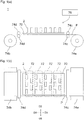
- printer 1 a color inkjet printer 1 (hereinafter referred to as printer 1) including a liquid discharge head 2 according to a first embodiment of the present invention will now be described herein.
- the printer 1 conveys a recording medium P from a conveying roller 74a to a conveying roller 74b to move the recording medium P relative to the liquid discharge head 2.
- a control section 76 controls the liquid discharge head 2 based on data such as an image and a text so as to discharge liquid toward the recording medium P to project droplets onto the recording medium P to perform printing on the recording medium P.
- the liquid discharge head 2 is fixed to the printer 1 so that the printer 1 operates as a line printer.
- Another embodiment of the recording device may be a serial printer.
- a tabular head mounting frame 70 is fixed approximately parallel to the recording medium P.
- 20 holes (not shown) are provided, and the 20 liquid discharge heads 2 are respectively mounted over the holes.
- the five liquid discharge heads 2 configure a head group 72, and the printer 1 has the four head groups 72.
- the liquid discharge head 2 has a thin, long shape, as shown in Fig. 1(b) .
- the three liquid discharge heads 2 are arranged along a direction intersecting a conveying direction of the recording medium P, while the other two liquid discharge heads 2 are each arranged between the three liquid discharge heads 2, but offset along the conveying direction.
- the adjoining liquid discharge heads 2 are disposed to join regions printable with the liquid discharge heads 2 in a width direction of the recording medium P, or to allow edges of the printable regions to overlap so that printing is possible in a seamless manner in the width direction of the recording medium P.
- a number of the liquid discharge heads 2 mounted on the printer 1 may be only one provided that the single liquid discharge head 2 prints a printable region with a single color.
- a number of the liquid discharge heads 2 included in each of the head groups 72 or a number of the head groups 72 may be appropriately changed depending on a print target or a print condition. For example, in order to perform further multi-color printing, a number of the head groups 72 may be increased.
- a print speed i.e. conveying speed
- a resolution in a width direction of the recording medium P may be increased.
- liquid such as a coating agent may be printed to perform a surface treatment for the recording medium P.
- the printer 1 performs printing onto the recording medium P.
- the recording medium P wound onto the conveying roller 74a passes between two conveying rollers 74c, and then passes under the liquid discharge heads 2 mounted on the head mounting frame 70. After that, the recording medium P passes between other two conveying rollers 74d, and is finally collected by the conveying roller 74b.
- the recording medium P may be cloth, in addition to printing paper.
- the printer 1 may convey a conveying belt, and, in addition to a roll-shaped recording medium, a sheet paper, a cut piece of cloth, a wooden material, or a tile may be placed on the conveying belt.
- the liquid discharge heads 2 may discharge liquid containing conductive particles to print a wiring pattern for an electronic device. Still further, the liquid discharge heads 2 may discharge, toward a reactor vessel, a predetermined amount of a liquid chemical agent or liquid containing a chemical agent for reaction to produce a chemical product.
- the printer 1 may be attached with a position sensor, a speed sensor, and a temperature sensor, so that the control section 76 controls components of the printer 1 in accordance with conditions of the components of the printer 1 known based on information sent from the sensors.
- a discharging characteristic discharge amount, discharge speed, and others
- a drive signal that causes the liquid discharge heads 2 to discharge the liquid may be changed in accordance with a temperature in the liquid discharge heads 2, a liquid temperature in the liquid tank, and a liquid pressure applied from the liquid tank to the liquid discharge heads 2.
- FIG. 5(a) a second flow passage member 6 is partially shown in transparent, and, in Fig. 5(b) , the second flow passage member 6 is entirely shown in transparent.
- Fig. 8 only a second individual flow passage is shown with a solid line, which is also applicable to Figs. 10 and 11 .
- Fig. 9 the second individual flow passage is shown with a broken line.
- first direction D1 is a direction toward which a first common flow passage 20 and a second common flow passage 24 extend
- fourth direction D4 is another direction toward which the first common flow passage 20 and the second common flow passage 24 extend
- second direction D2 is a direction toward which a first integrated flow passage 22 and a second integrated flow passage 26 extend
- fifth direction D5 is another direction toward which the first integrated flow passage 22 and the second integrated flow passage 26 extend.
- the third direction D3 is a direction orthogonal to the direction toward which the first integrated flow passage 22 and the second integrated flow passage 26 extend
- the sixth direction D6 is another direction orthogonal to the other direction toward which the first integrated flow passage 22 and the second integrated flow passage 26 extend.
- the liquid discharge head 2 is described with a first individual flow passage 12, as the first flow passage, the first common flow passage 20, as the second flow passage, a second individual flow passage 14, as the third flow passage, and the second common flow passage 24, as the fourth flow passage.
- the liquid discharge head 2 includes a head body 2a, a housing 50, heat sinks 52, a circuit board 54, a press member 56, elastic members 58, signal transmission sections 60, and driver ICs 62.
- the liquid discharge head 2 may at least include the head body 2a, and may not necessarily include the housing 50, the heat sinks 52, the circuit board 54, the press member 56, the elastic members 58, the signal transmission sections 60, and the driver ICs 62.
- the signal transmission sections 60 extend from the head body 2a, and the signal transmission sections 60 are electrically connected to the circuit board 54.
- the signal transmission sections 60 are provided with the driver ICs 62 for driving and controlling the liquid discharge head 2.
- the driver ICs 62 are pressed onto the heat sinks 52 by the press member 56 via the elastic members 58.
- a supporting member supporting the circuit board 54 is omitted from the drawings.
- the heat sinks 52 may be formed of a metal or an alloy, and are provided to externally radiate heat of the driver ICs 62.
- the heat sinks 52 are joined to the housing 50 by means of a screw or an adhesive.
- the housing 50 is mounted on the head body 2a so that the housing 50 and the heat sinks 52 cover each member configuring the liquid discharge head 2.
- the housing 50 includes openings 50a, 50b, and 50c, and thermal insulation sections 50d.
- the openings 50a are provided to respectively face the third direction D3 and the sixth direction D6, and the first openings 50a are disposed with the heat sinks 52.
- the second opening 50b opens downwardly so that, via the second opening 50b, the circuit board 54 and the press member 56 are disposed inside the housing 50.
- the third opening 50c opens upwardly to house a connector (not shown) provided for the circuit board 54.
- the thermal insulation sections 50d are provided to extend from the second direction D2 to the fifth direction D5, and are disposed between the heat sinks 52 and the head body 2a. Therefore, heat radiated to the heat sinks 52 is prevented as much as possible from being transmitted to the head body 2a.
- the housing 50 may be formed of a metal, an alloy, or a resin.
- the first flow passage member 4 is internally formed with flow passages to guide liquid supplied from the second flow passage member 6 to a discharge hole 8.
- a pressurizing chamber surface 4-1 is formed on a main surface, and, on the pressurizing chamber surface 4-1, openings 20a and 24a are formed.
- the openings 20a are arranged from the second direction D2 to the fifth direction D5, and are disposed on an edge, in the third direction D3, of the pressurizing chamber surface 4-1.
- the openings 24a are arranged from the second direction D2 to the fifth direction D5, and are disposed on another edge, in the sixth direction D6, of the pressurizing chamber surface 4-1.
- the second flow passage member 6 is internally formed with flow passages to guide liquid supplied from the liquid tank to the first flow passage member 4.
- the second flow passage member 6 is provided on an outer periphery portion of a pressurizing chamber surface 4a-1 of the first flow passage member 4, and is joined to the first flow passage member 4, via an adhesive (not shown), outside the mount region of the piezoelectric actuator substrate 40.
- the second flow passage member 6 is, as shown in Figs. 4 and 5 , formed with through holes 6a, and openings 6b, 6c, 6d, 22a, and 26a.
- the through holes 6a are formed to extend from the second direction D2 to the fifth direction D5, and are disposed outside the mount region of the piezoelectric actuator substrate 40.
- the through holes 6a are inserted with the signal transmission sections 60.
- the opening 22a is provided on the under surface of the second flow passage member 6, and extends from the second direction D2 to the fifth direction D5.
- the opening 22a is formed on an edge, in the third direction D3, of the second flow passage member 6 so as to face toward the third direction D3 farther from the through hole 6a.
- the opening 22a communicates with the opening 6b, and forms the first integrated flow passage 22 when the opening 22a is sealed by the first flow passage member 4.
- the first integrated flow passage 22 is formed to extend from the second direction D2 to the fifth direction D5 to supply liquid to the openings 20a of the first flow passage member 4.
- the opening 26a is provided on the under surface of the second flow passage member 6, and extends from the second direction D2 to the fifth direction D5.
- the opening 26a is formed on another edge, in the sixth direction D6, of the second flow passage member 6 so as to face toward the sixth direction D6 farther from the through hole 6a.
- the opening 26a communicates with the opening 6b, and forms the second integrated flow passage 26 when the opening 26a is sealed by the first flow passage member 4.
- the second integrated flow passage 26 is formed to extend from the second direction D2 to the fifth direction D5 to collect the liquid from the openings 24a of the first flow passage member 4.
- liquid supplied from the liquid tank to the opening 6b is supplied to the first integrated flow passage 22, and flows, via the opening 22a, into the first common flow passage 20 so that the liquid is supplied into the first flow passage member 4. And then the liquid collected through the second common flow passage 24 flows, via the opening 26a, into the second integrated flow passage 26 so that the liquid is collected externally via the opening 6c.
- the second flow passage member 6 may not necessarily be provided.
- the first flow passage member 4 is formed by laminating a plurality of plates 4a to 4g, and has the pressurizing chamber surface 4-1 and a discharge hole surface 4-2.
- the piezoelectric actuator substrate 40 is disposed so that liquid is discharged from the discharge hole 8 having a discharge port 8c opened on the discharge hole surface 4-2.
- a plurality of the plates 4a to 4g may each be formed of a metal, an alloy, or a resin.
- the first flow passage member 4 may not be laminated with a plurality of the plates 4a to 4g, but may be integrally formed of a resin.
- first flow passage member 4 a plurality of first common flow passages 20, a plurality of second common flow passages 24, and a plurality of individual units 15 are formed, and the pressurizing chamber surface 4-1 is formed with openings 20a and 24a.
- Discharge units 15 each include, as shown in Fig. 7(a) , the discharge hole 8, the pressurizing chamber 10, the first individual flow passage 12, and the second individual flow passage 14.
- the discharge units 15 are provided between the adjoining first common flow passages 20 and the second common flow passages 24, and are formed in a matrix shape in a surface direction of the first flow passage member 4.
- the discharge units 15 have discharge unit columns 15a and discharge unit lines 15b.
- the discharge unit columns 15a are arranged from the first direction D1 to the fourth direction D4, and the discharge unit lines 15b are arranged from the second direction D2 to the fifth direction D5.
- pressurizing chamber columns 10c and discharge hole columns 8a are also arranged from the first direction D1 to the fourth direction D4.
- pressurizing chamber lines 10d and discharge hole lines 8b are also arranged from the second direction D2 to the fifth direction D5.
- Angles between a line formed by the first direction D1 and the fourth direction D4 and a line formed by the second direction D2 and the fifth direction D5 are each offset from a right angle. Because of this, the discharge holes 8 belonging to the discharge hole columns 8a disposed from the first direction D1 to the fourth direction D4 are each other disposed by the offset from the right angle toward the second direction D2. Since the discharge hole columns 8a are disposed in parallel to the second direction D2, the discharge holes 8 belonging to the different discharge hole columns 8a are disposed by the offset toward the second direction D2. In combination of these offsets, the discharge holes 8 of the first flow passage member 4 are disposed at a predetermined interval in the second direction D2. Therefore, printing is possible to fill a predetermined region with a pixel formed by the discharged liquid.
- the discharge units 15 each include, as shown in Fig. 7 , the discharge hole 8, the pressurizing chamber 10, the first individual flow passage 12, and the second individual flow passage 14. Moreover, in the liquid discharge head 2, liquid is supplied from the first individual flow passages 12 to the pressurizing chambers 10, and collected by the second individual flow passages 14 from the pressurizing chambers 10.
- the pressurizing chamber 10 has a pressurizing chamber body 10a and a partial flow passage 10b.
- the pressurizing chamber body 10a forms a circular shape, when viewed in a plane, and the partial flow passage 10b extends downwardly from a center of the pressurizing chamber body 10a.
- the pressurizing chamber body 10a is configured to accept pressure from the displacement element 48 disposed on the pressurizing chamber body 10a to pressurize liquid in the partial flow passage 10b.
- the pressurizing chamber body 10a has a cylindrical shape, and its planar shape shows a circular shape.
- the planar shape showing the circular shape can increase an amount of displacement, and therefore can increase a volumetric change caused by the displacement in each of the pressurizing chambers 10.
- the partial flow passage 10b has a cylindrical shape having a diameter smaller than a diameter of the pressurizing chamber body 10a, and its planar shape shows a circular shape.
- the partial flow passage 10b has a pressurizing chamber under surface 10b1 and a side surface 10b2, and is disposed, when viewed from the pressurizing chamber surface 4-1, at a position fitting within the pressurizing chamber body 10a.
- the partial flow passage 10b connects the pressurizing chamber body 10a and the discharge hole 8.
- the pressurizing chambers 10 are disposed along both sides of each of the first common flow passages 20 to configure the pressurizing chamber columns 10c, one column on each side, two columns in total.
- the first common flow passages 20 and the pressurizing chambers 10 disposed in parallel on both sides of each of the first common flow passages 20 are connected via the first individual flow passages 12.
- pressurizing chambers 10 are disposed along both sides of each of the second common flow passages 24 to configure the pressurizing chamber columns 10c, one column on each side, two columns in total.
- the second common flow passages 24 and the pressurizing chambers 10 disposed in parallel on both sides of each of the second common flow passages 24 are connected via the second individual flow passages 14.
- the first individual flow passages 12 each connect each of the first common flow passages 20 and the pressurizing chamber body 10a. After extended upwardly from upper surfaces of the first common flow passages 20, the first individual flow passages 12 are each connected to an under surface of the pressurizing chamber body 10a.
- liquid supplied, via the openings 20a, to the first common flow passages 20 flows, via the first individual flow passages 12, into the pressurizing chamber bodies 10a, supplied to the partial flow passages 10b, and is partially discharged from the discharge holes 8. And then the remaining liquid is collected from the partial flow passages 10b, via the second individual flow passages 14, to the second common flow passages 24, and then collected from the first flow passage member 4, via the openings 24a, to the second flow passage member 6.
- the piezoelectric actuator substrate 40 including the displacement elements 48 is joined so that the displacement elements 48 are disposed in position on the pressurizing chambers 10.
- the piezoelectric actuator substrate 40 occupies a region having a shape approximately identical to a shape of a pressurizing chamber group formed with the pressurizing chambers 10.
- an opening of each of the pressurizing chambers 10 closes when the piezoelectric actuator substrate 40 is joined onto the pressurizing chamber surface 4-1 of the first flow passage member 4.
- the piezoelectric actuator substrate 40 has a structure laminated with two piezoelectric ceramic layers 40a and 40b each including a piezoelectric material.
- the piezoelectric ceramic layers 40a and 40b each have a thickness of approximately 20 ⁇ m. Both the piezoelectric ceramic layers 40a and 40b extend over a plurality of the pressurizing chambers 10.
- the piezoelectric ceramic layers 40a and 40b include, for example, a ceramic material having ferroelectricity, such as lead zirconate titanate (PZT) type, NaNbO 3 type, BaTiO 3 type, (BiNa)NbO 3 type, and BiNaNb 5 O 15 type.
- the piezoelectric ceramic layer 40b functions as a vibrating plate, and does not necessarily include a piezoelectric material, but may use a ceramic layer other than piezoelectric material and a metal plate.
- the piezoelectric actuator substrate 40 is formed with a common electrode 42, individual electrodes 44, and connection electrodes 46.
- the common electrode 42 is formed almost entirely in a surface direction on a region between the piezoelectric ceramic layer 40a and the piezoelectric ceramic layer 40b.
- the individual electrodes 44 are respectively disposed at positions on an upper surface of the piezoelectric actuator substrate 40 so as to face the pressurizing chambers 10.
- the piezoelectric actuator substrate 40 has a plurality of the displacement elements 48.
- the common electrode 42 can be formed of a metallic material such as Ag-Pd type, and a thickness of the common electrode 42 may be approximately 2 ⁇ m.
- the common electrode 42 has a surface electrode (not shown) for common electrode on the piezoelectric ceramic layer 40a, and the surface electrode for common electrode is connected to the common electrode 42 via a via hole formed when the surface electrode for common electrode penetrates into the piezoelectric ceramic layer 40a, and is grounded so that a ground potential is retained.
- the individual electrodes 44 are each formed of a metallic material such as Au type, and each have an individual electrode body 44a and an extraction electrode 44b. As shown in Fig. 7(c), the individual electrode body 44a is formed in an approximately circular shape when viewed in a plane, and is formed smaller than the pressurizing chamber body 10a.
- the extraction electrode 44b extends from the individual electrode body 44a, and, onto the extended extraction electrode 44b, the connection electrodes 46 are formed.
- connection electrodes 46 include, for example, silver-palladium including glass frit, and are each formed protrudingly with a thickness of approximately 15 ⁇ m.
- the connection electrodes 46 are electrically joined to electrodes provided to the signal transmission sections 60.
- the second individual flow passage 14 has a wide section 14a, a narrow section 14b, and a connection section 14c.
- the wide section 14a is connected to the partial flow passage 10b, and formed wider than the narrow section 14b.
- a width of the wide section 14b gradually expands toward the partial flow passage 10b, i.e. in the fourth direction D4.
- the narrow section 14b connects the wide section 14a and each of the second common flow passages 24 via the connection section 14c, and is formed narrower than the wide section 14a.
- the narrow section 14b is formed with a curved section 14b1 that curves in a middle.
- the narrow section 14b has an approximately constant width, and, after extended from the wide section 14a in the first direction D1, curves at the curved section 14b1, and then extends in a direction orthogonal to the first direction D1 and the fourth direction D4, to connect to the under surface of each of the second common flow passages 24.
- connection section 14c connects the wide section 14a and the narrow section 14b.
- a wall configuring the connection section 14c curves, when viewed in a plane. That is, as the connection section 14c extends, along the first direction D1 and the fourth direction D4, toward the partial flow passage 10b, the connection section 14c gradually curves in the direction orthogonal to the first direction D1 and the fourth direction D4.
- the pressurizing chambers 10 each have a connection region 10e connected to the wide section 14a.
- the connection region 10e is formed over an arc of the partial flow passage 10b, and has a semicircular shape.
- the pressurizing chambers 10 are each shown with a virtual line 10f connecting an end and another end of the connection region 10e, and, when viewed in a plane, each include the first region E1 surrounded by the connection region 10e and the virtual line 10f.
- the pressurizing chambers 10 each include the second region E2 overlapping with an region extending in the fourth direction D4 from the narrow section 14b.
- the liquid discharge head 2 since the wide section 14a is disposed to face the discharge hole 8 of the partial flow passage 10b, as shown in Fig. 9(b) , liquid flowing into the liquid discharge head 2 flows so as to spread out inside the partial flow passage 10b. Therefore, the partial flow passage 10b can be prevented as much as possible from being internally created with the region 80 (see Fig. 9(a) ) in which the liquid stagnates. In addition, the liquid can flow without being stagnated toward the discharge hole 8 of the partial flow passage 10b, and, as a result, a pigment or other materials contained in the liquid can be prevented from being settled to prevent as much as possible the discharge hole 8 from being clogged.
- the second individual flow passage 14 includes the wide section 14a and the narrow section 14b so that the wide section 14a can prevent the partial flow passage 10b from being internally created with a region in which liquid stagnates, and the narrow section 14b can reduce unevenness in pressure loss in each of the discharge units 15.
- a direction toward the discharge hole 8 of the partial flow passage 10b means that the wide section 14a is connected, on the side surface 10b2 of the partial flow passage 10b, to a region at a height of up to 0.5 times of a height from the pressurizing chamber under surface 10b1 to the partial flow passage 10b. Moreover, it is advantageous that the wide section 14a is connected to a region at a height of up to 0.2 times of a height from the pressurizing chamber under surface 10b1 to the partial flow passage 10b.
- a cross-sectional area of the wide section 14a is 2 to 8 times of a cross-sectional area of the narrow section 14b.
- a width of the wide section 14a is 2 to 8 times of a width of the narrow section 14b.
- liquid flowing into the second individual flow passage 14 can be supplied, after the wide section 14a causes the liquid to flow in a wider region, to the partial flow passage 10b.
- the partial flow passage 10b can be prevented as much as possible from being internally created with the region 80 in which the liquid stagnates.
- the width of the wide section 14a means a length orthogonal to the first direction D1 and the fourth direction D4, and, unless otherwise described, means the width of the wide section 14a connected to the connection region 10e.
- the width of the narrow section 14b means a length orthogonal to the first direction D1 and the fourth direction D4, and, unless otherwise described, represents the width of the narrow section 14b around the connection section 14c.
- the cross-sectional area of the wide section 14a may be increased by increasing a depth of the wide section 14a.
- the width of the wide section 14a expands toward the partial flow passage 10b. Accordingly, the liquid flowing into the second individual flow passage 14 flows in a wider region as the liquid flows along the side surface of the wide section 14a. As a result, the liquid can flow in a wider region inside the partial flow passage 10b, thus the partial flow passage 10b can be prevented as much as possible from being internally created with the region 80 in which the liquid stagnates.
- the wide section 14a has, when viewed in a plane, an approximately circular shape. Accordingly, the liquid supplied from the narrow section 14b expands along the side surface of the wide section 14a, thus the wide section 14a can be prevented as much as possible from being internally created with a region in which the liquid stagnates.
- the second individual flow passage 14 includes the connection section 14c, and, when viewed in a plane, the wall configuring the connection section 14c is curved. Therefore, the liquid flowed into the narrow section 14b can flow without being stagnated into the wide section 14a. That is, the region 80 in which the liquid stagnates around the connection section 14c can be prevented as much as possible from being created.
- the width of the wide section 14a in the connection region 10e is approximately identical to a width of the partial flow passage 10b. Therefore, a region in which the liquid spreads out by the wide section 14a can expand close to the width of the partial flow passage 10b. As a result, the partial flow passage 10b can be prevented as much as possible from being internally created with the region 80 in which the liquid stagnates.
- the discharge hole 8 when viewed in a plane, the discharge hole 8 is disposed in the first region E1. Therefore, a region in which the liquid stagnates around the discharge hole 8 can be prevented as much as possible from being created. That is, the provided wide section 14a causes, in the first region E1, the liquid to flow in a wider region. In addition, the discharge hole 8 disposed in the first region E1 can prevent as much as possible liquid from being stagnated around the discharge hole 8.
- the discharge hole 8 is entirely disposed in the first region E1.
- the discharge hole 8 when viewed in a plane, the discharge hole 8 is disposed in the second region E2. Therefore, a region in which liquid stagnates around the discharge hole 8 can further be prevented as much as possible from being created. That is, since the width of the narrow section 14b is narrower than the width of the partial flow passage 10b, liquid flows into the narrow section 14b at a speed higher than a speed of the liquid flowing into the partial flow passage 10b.
- An inertia force applied to the liquid flowing into the narrow section 14b causes the liquid to flow at a higher speed into a region extended from the narrow section 14b in the fourth direction D4. Accordingly, the liquid flows into the second region E2 at a speed higher than a speed of the liquid flowing into another region, thus, the liquid can flow at a higher speed around the discharge hole 8 disposed in the second region E2. As a result, the discharge hole 8 can be prevented as much as possible from being clogged.
- the pressurizing chambers 10 are disposed between the first common flow passages 20 and the second common flow passages 24, where the second individual flow passages 14 extend from the pressurizing chambers 10 in the first direction D1. Therefore, the pressurizing chambers 10 can densely be disposed, while paste allowances for plates 4e to 4g of the first flow passage member 4 can be maintained. In addition, being extended from the pressurizing chambers 10 in the first direction D1, a length of each of the second individual flow passages 14 can be secured to reduce a flow passage resistance in the second individual flow passages 14.
- the narrow section 14b has the curved section 14b1 curving toward each of the second common flow passages 24, where a radius of curvature of the curved section 14b1 is at least a half of a distance between each of the first common flow passages 20 and the second common flow passages 24. Therefore, an amount of the flowing liquid increases to prevent, if a flow passage resistance increases, a flow passage resistance for the liquid flowing into the curved section 14b1 from being increased excessively.
- the pressurizing chambers 10 each include the pressurizing chamber body 10a and the partial flow passage 10b, where the wide section 14a is disposed toward the discharge hole 8 of the partial flow passage 10b.
- the partial flow passage 10b is connected to the pressurizing chamber body 10a and the second individual flow passage 14b, where, when liquid is supplied from the pressurizing chamber body 10a, a region in which the liquid stagnates internally can easily be created.
- the liquid discharge head 2 can allow liquid to flow without being stagnated toward the discharge hole 8 of the partial flow passage 10b, and, as a result, a pigment or other materials contained in the liquid can be prevented from being settled to prevent as much as possible the discharge hole 8 from being clogged.
- a meaning of an identical height is not limited to a meaning that a height, from the discharge port 8c, of the wide section under surface 14d and a height, from the discharge port 8c, of the pressurizing chamber under surface 10b1 are completely identical, but can include a difference in height due to a manufacturing error or other reasons. That is, an identical height means a substantially identical height.
- the height, from the discharge port 8c, of the wide section under surface 14d may be lower than the height, from the discharge port 8c, of the pressurizing chamber under surface 10b1. In that case, liquid can flow at a further higher speed around the discharge port 8c formed on the pressurizing chamber under surface 10b1.
- the liquid discharge head 2 supplies liquid from the first common flow passages 20, via the first individual flow passages 12, to a plurality of the pressurizing chambers 10, and collects the liquid in a plurality of the pressurizing chambers 10 from the second common flow passages 24 via the second individual flow passages 14. Therefore, the liquid flows, inside the partial flow passage 10b, from the discharge hole 8 toward the pressurizing chamber body 10a. As a result, even if an air bubble enters from the discharge port 8c into the partial flow passage, the air bubble can flow upwardly, in addition to buoyancy of the air bubble, by the flowing liquid. As a result, the air bubble can flow, via the pressurizing chamber body 10a, into each of the first common flow passages 20 to exit externally.
- the pressurizing chambers 10 each include the pressurizing chamber body 10a and the partial flow passage 10b
- the pressurizing chamber body 10a may be shaped to extend downwardly to exclude the partial flow passage 10b.
- a region toward the discharge hole 8 of the pressurizing chamber 10 means that the wide section 14a is connected, on the side surface 10b2 of the pressurizing chamber body 10a, to a region at a height of up to 0.5 times of a height from the pressurizing chamber under surface 10b1 to the pressurizing chamber body 10a. Moreover, it is advantageous that the wide section 14a is connected to a region at a height of up to 0.2 times of a height from the pressurizing chamber under surface 10b1 to the pressurizing chamber body 10a.
- the liquid discharge head 102 includes a second individual flow passage 114 that differs from the second individual flow passage of the liquid discharge head 2, but other points are identical to points of the liquid discharge head 2. Moreover, identical members are applied with identical reference characters.
- liquid flowed into the wide section 114a can flow entirely inside the partial flow passage 10b. That is, a region in which the liquid flows in the wide section 114a expands to, as a result, prevent as much as possible the liquid from being stagnated inside the partial flow passage 10b.
- connection region 10e having a diameter identical to a diameter of the partial flow passage 10b represented by the virtual line 10f is provided. Therefore, the first region E1 can expand to prevent as much as possible the wide section 14 from being internally created with a region in which liquid stagnates.
- the liquid discharge head 202 includes a second individual flow passage 214 that differs from the second individual flow passage of the liquid discharge head 2, but other points are identical. Moreover, identical members are applied with identical reference characters.
- the second individual electrode 214 has a wide section 214a, a narrow section 214b, and a connection section 214c.
- the wide section 214a is formed straight, when viewed in a plane, and has a constant width approximately identical to the width of the partial flow passage 10b.
- liquid flowed into the wide section 114a can flow and spread out inside the partial flow passage 10b. That is, a region in which the liquid flows in the wide section 114a expands to, as a result, prevent as much as possible the liquid from being stagnated inside the partial flow passage 10b.
- the width of the wide section 14a expands toward a partial flow passage 19b. Therefore, the wide section 14 can be prevented as much as possible from being created with a region in which the liquid stagnates.
- liquid discharge head 302 according to a second embodiment will now be described herein. Moreover, in the liquid discharge head 302, various flow passages formed in a first flow passage member 304 and liquid flow directions differ from the flow passages and directions of the liquid discharge head 2, but other points are identical, so descriptions of the other points are omitted.
- the first flow passage member 304 includes a first common flow passage 320 and a second common flow passage 324.
- the first common flow passage 320 is connected with a first individual flow passage 312, and the second common flow passage 324 is connected with a second individual flow passage 314.
- the first common flow passage 320 is connected, via the openings 20a (see Fig. 4 ), to the first integrated flow passage 22 (see Fig. 4 ) of the second flow passage member 6 (see Fig. 4 ).
- the second common flow passage 324 is connected, via the openings 24a (see Fig. 4 ), to the second integrated flow passage 26 (see Fig. 4 ) of the second flow passage member 6.
- the liquid discharge head 302 is supplied with liquid in a direction opposite to a direction toward which the liquid discharge head 2 is supplied with liquid. That is, the liquid supplied to the second integrated flow passage 26 is supplied, via each of the openings 24a, to the second common flow passage 324. The liquid supplied to the second common flow passage 324 is supplied, via the second individual flow passage 314, to a partial flow passage 310b. The liquid supplied to the partial flow passage 310b is partially discharged from a discharge hole 308, and the remaining liquid is supplied to a pressurizing chamber body 310a. The liquid supplied to the pressurizing chamber body 310a is collected, via the first individual flow passage 312, into the first common flow passage 320. The liquid collected by the first common flow passage 320 is collected, via the openings 20a, into the first integrated flow passage 22. As described above, the liquid discharge head 302 is formed with a circular structure by the first flow passage member 304 and the second flow passage member 6.
- a pressurizing chamber 310 includes the pressurizing chamber body 310a and the partial flow passage 310b having a cross-sectional area smaller than a cross-sectional area of the pressurizing chamber body 310a.
- the pressurizing chamber body 310a and the partial flow passage 310b each have a circular cross-sectional shape, and an area center of gravity of the pressurizing chamber body 310a does not conform to an area center of gravity of the partial flow passage 310b where the area center of gravity of the partial flow passage 310b is disposed closer toward the first direction D1 than the area center of gravity of the pressurizing chamber body 310a.
- the pressurizing chamber body 310a is connected, toward the fourth direction, to the first individual flow passage 312.
- the pressurizing chamber 310 has a first region E1 and a second region E2.
- the discharge hole 308 is disposed on the first region E1 and the second region E2. That is, the discharge hole 308 is disposed on a region where the first region E1 and the second region E2 overlap.
- the second individual flow passage 314 includes a wide section 314a, a narrow section 314b, and a connection section 314c, and is connected to the partial flow passage 310b and a connection region 310e.
- Liquid supplied from the partial flow passage 310b to the pressurizing chamber body 310a is collected into the first individual flow passage 312.
- an area center of gravity of the pressurizing chamber body 310a conforms to an area center of gravity of the partial flow passage 310b
- the first individual flow passage 312 is connected to the pressurizing chamber body 310a in the fourth direction D4
- liquid supplied from the partial flow passage 310b to the pressurizing chamber body 310a flows in the fourth direction D4, thus the liquid likely stagnates toward the first direction D1 in the pressurizing chamber body 310a.
- an outer periphery of the partial flow passage 310b and an outer periphery of the pressurizing chamber body 310a overlap. Therefore, the liquid is further prevented as much as possible from being stagnated inside the pressurizing chamber body 310a.
- the liquid discharge head 302 supplies liquid from the second common flow passages 324, via the second individual flow passages 314, to a plurality of the pressurizing chambers 310, and collects the liquid in a plurality of the pressurizing chambers 310 from the first common flow passages 320 via the first individual flow passages 312. Therefore, the liquid present around the discharge holes 8 is facilitated to flow, thus liquid can flow at a higher speed under pressurizing chamber under surfaces 310b3 and 310b4.
- a liquid discharge head 402 according to a modification example of the second embodiment will now be described herein.
- a pressurizing chamber 410 and a second individual flow passage 412 differ from the chambers and passages of the liquid discharge head 302.
- the pressurizing chamber 410 includes a pressurizing chamber body 410a and a partial flow passage 410b.
- the partial flow passage 410b has a side surface 410b2, a pressurizing chamber under surface 410b4 positioned toward the first direction D1, and a pressurizing chamber under surface 410b3 positioned toward the fourth direction D4.
- a height, from a discharge port 308c, of the pressurizing chamber under surface 410b4 positioned toward the first direction D1 is lower than a height, from the discharge port 308c, of the pressurizing chamber under surface 410b3 positioned toward the fourth direction D4.
- the liquid discharge head 402 is not formed with the partial flow passage 410b in a region in which liquid is difficult to flow. Therefore, the liquid can be prevented as much as possible from being stagnated inside the partial flow passage 410b.
- a wide section under surface 414d of a second individual flow passage 414 and the pressurizing chamber under surface 410b4 positioned toward the first direction D1 are formed flush. Therefore, the liquid can be prevented as much as possible from being stagnated in a connection region (not shown) between the wide section 414a and the partial flow passage 410b. Further, the liquid can flow at a higher speed around the discharge hole 308 to prevent as much as possible the discharge hole 308 from being clogged.
- the pressurizing section the pressurizing chamber 10 is pressurized through a piezoelectric deformation of a piezoelectric actuator, but the pressurizing section is not limited to this example.
- a pressurizing section may provide a heating section per each of the pressurizing chambers 10 to heat liquid in the pressurizing chambers 10 with the heating sections to pressurize the liquid through thermal expansion.
Landscapes
- Particle Formation And Scattering Control In Inkjet Printers (AREA)
- Ink Jet (AREA)
Applications Claiming Priority (2)
| Application Number | Priority Date | Filing Date | Title |
|---|---|---|---|
| JP2014065771 | 2014-03-27 | ||
| PCT/JP2015/059808 WO2015147307A1 (ja) | 2014-03-27 | 2015-03-27 | 液体吐出ヘッド、および記録装置 |
Publications (3)
| Publication Number | Publication Date |
|---|---|
| EP3124251A1 true EP3124251A1 (de) | 2017-02-01 |
| EP3124251A4 EP3124251A4 (de) | 2017-11-15 |
| EP3124251B1 EP3124251B1 (de) | 2020-11-11 |
Family
ID=54195810
Family Applications (1)
| Application Number | Title | Priority Date | Filing Date |
|---|---|---|---|
| EP15769121.3A Active EP3124251B1 (de) | 2014-03-27 | 2015-03-27 | Flüssigkeitsausstosskopf und aufzeichnungsvorrichtung |
Country Status (5)
| Country | Link |
|---|---|
| US (1) | US10155381B2 (de) |
| EP (1) | EP3124251B1 (de) |
| JP (1) | JP6248181B2 (de) |
| CN (1) | CN106103101B (de) |
| WO (1) | WO2015147307A1 (de) |
Families Citing this family (7)
| Publication number | Priority date | Publication date | Assignee | Title |
|---|---|---|---|---|
| JP6750843B2 (ja) * | 2016-02-15 | 2020-09-02 | キヤノン株式会社 | 液体吐出ヘッド |
| GB2547951A (en) | 2016-03-04 | 2017-09-06 | Xaar Technology Ltd | Droplet deposition head and manifold component therefor |
| CN109641460B (zh) * | 2016-09-23 | 2020-09-29 | 京瓷株式会社 | 液体喷出头以及记录装置 |
| JP7419677B2 (ja) * | 2019-06-05 | 2024-01-23 | ブラザー工業株式会社 | 液体吐出ヘッド |
| WO2021037510A1 (en) * | 2019-08-27 | 2021-03-04 | Memjet Technology Limited | Mems inkjet printhead having recirculating ink pathway |
| JP7415499B2 (ja) | 2019-12-04 | 2024-01-17 | ブラザー工業株式会社 | 液体吐出ヘッド |
| JP7467917B2 (ja) | 2020-01-06 | 2024-04-16 | ブラザー工業株式会社 | 液体吐出ヘッド |
Family Cites Families (27)
| Publication number | Priority date | Publication date | Assignee | Title |
|---|---|---|---|---|
| JP3158671B2 (ja) * | 1992-07-07 | 2001-04-23 | セイコーエプソン株式会社 | インクジェットヘッド及びその駆動方法 |
| JP3706671B2 (ja) | 1995-04-14 | 2005-10-12 | キヤノン株式会社 | 液体吐出ヘッド、液体吐出ヘッドを用いたヘッドカートリッジ、液体吐出装置、および液体吐出方法 |
| JP2004284253A (ja) * | 2003-03-24 | 2004-10-14 | Fuji Xerox Co Ltd | インクジェット記録ヘッド及びインクジェット記録装置 |
| EP1541354B1 (de) * | 2003-12-09 | 2008-11-26 | Brother Kogyo Kabushiki Kaisha | Tintenstrahlkopf und Tintenstrahlkopfdüsenplatte |
| JP3965586B2 (ja) * | 2004-03-31 | 2007-08-29 | 富士フイルム株式会社 | 液滴吐出ヘッド及び画像形成装置 |
| JP4662027B2 (ja) * | 2004-12-22 | 2011-03-30 | ブラザー工業株式会社 | インクジェットヘッド及びその製造方法 |
| JP4682619B2 (ja) * | 2004-12-28 | 2011-05-11 | ブラザー工業株式会社 | フレキシブル配線基板、基板テープ、インクジェットヘッド及びインクジェットヘッドの製造方法 |
| JP4808454B2 (ja) * | 2005-09-07 | 2011-11-02 | 株式会社アルバック | 印刷ヘッド及び印刷装置 |
| JP4761036B2 (ja) * | 2005-10-14 | 2011-08-31 | ブラザー工業株式会社 | インクジェットヘッド及びその製造方法 |
| JP5013042B2 (ja) * | 2005-11-04 | 2012-08-29 | ブラザー工業株式会社 | インクジェットヘッド |
| JP4947259B2 (ja) * | 2005-11-04 | 2012-06-06 | ブラザー工業株式会社 | インクジェットヘッド |
| JP4875997B2 (ja) * | 2007-02-16 | 2012-02-15 | 富士フイルム株式会社 | 液体吐出ヘッドおよび液体吐出装置 |
| KR20080096275A (ko) * | 2007-04-27 | 2008-10-30 | 삼성전기주식회사 | 잉크젯 헤드 |
| KR101391808B1 (ko) * | 2007-07-03 | 2014-05-08 | 삼성디스플레이 주식회사 | 압전 방식의 잉크젯 헤드 |
| JP4968040B2 (ja) | 2007-12-17 | 2012-07-04 | 富士ゼロックス株式会社 | 液滴吐出ユニット、液滴吐出ヘッド、及びこれを備えた画像形成装置 |
| WO2009142894A1 (en) | 2008-05-23 | 2009-11-26 | Fujifilm Corporation | Nozzle layout for fluid droplet ejecting |
| CN102026813B (zh) * | 2008-05-23 | 2015-05-27 | 富士胶片株式会社 | 流体液滴喷射装置 |
| US8651624B2 (en) * | 2008-10-14 | 2014-02-18 | Hewlett-Packard Development Company, L.P. | Fluid ejector structure |
| CN102448727B (zh) * | 2009-05-27 | 2014-09-17 | 京瓷株式会社 | 液体喷出头及使用其的记录装置 |
| JP5161986B2 (ja) * | 2010-04-05 | 2013-03-13 | パナソニック株式会社 | インクジェットヘッドおよびインクジェット装置 |
| JP5457935B2 (ja) * | 2010-05-12 | 2014-04-02 | パナソニック株式会社 | インクジェットヘッドおよびインクジェット装置ならびにそれらの製造方法 |
| JP2012006350A (ja) * | 2010-06-28 | 2012-01-12 | Fujifilm Corp | 液滴吐出ヘッド |
| JP5495385B2 (ja) * | 2010-06-30 | 2014-05-21 | 富士フイルム株式会社 | 液滴吐出ヘッド |
| US8657420B2 (en) * | 2010-12-28 | 2014-02-25 | Fujifilm Corporation | Fluid recirculation in droplet ejection devices |
| JP5302378B2 (ja) * | 2011-01-14 | 2013-10-02 | パナソニック株式会社 | インクジェットヘッド |
| US20120249687A1 (en) * | 2011-03-30 | 2012-10-04 | Price Brian G | Inkjet chamber refill method with circulating flow |
| JP5307858B2 (ja) * | 2011-07-22 | 2013-10-02 | 株式会社アルバック | 印刷ヘッド及び印刷装置 |
-
2015
- 2015-03-27 JP JP2016510574A patent/JP6248181B2/ja active Active
- 2015-03-27 US US15/128,263 patent/US10155381B2/en active Active
- 2015-03-27 WO PCT/JP2015/059808 patent/WO2015147307A1/ja active Application Filing
- 2015-03-27 EP EP15769121.3A patent/EP3124251B1/de active Active
- 2015-03-27 CN CN201580016054.XA patent/CN106103101B/zh active Active
Also Published As
| Publication number | Publication date |
|---|---|
| US10155381B2 (en) | 2018-12-18 |
| JPWO2015147307A1 (ja) | 2017-04-13 |
| US20170239948A1 (en) | 2017-08-24 |
| EP3124251B1 (de) | 2020-11-11 |
| EP3124251A4 (de) | 2017-11-15 |
| JP6248181B2 (ja) | 2017-12-13 |
| CN106103101B (zh) | 2018-06-12 |
| CN106103101A (zh) | 2016-11-09 |
| WO2015147307A1 (ja) | 2015-10-01 |
Similar Documents
| Publication | Publication Date | Title |
|---|---|---|
| EP3124251B1 (de) | Flüssigkeitsausstosskopf und aufzeichnungsvorrichtung | |
| EP3199354B1 (de) | Flüssigkeitsausstosskopf und aufzeichnungsvorrichtung | |
| US10189255B2 (en) | Liquid discharge head and recording device | |
| EP3162567A1 (de) | Kanalelement, flüssigkeitsausstosskopf und aufzeichnungsvorrichtung | |
| EP3109047B1 (de) | Flüssigkeitsentladungskopf und aufzeichnungsvorrichtung damit | |
| EP3248783B1 (de) | Flüssigkeitsentladungskopf und aufzeichnungsvorrichtung mit verwendung davon | |
| US9403364B2 (en) | Liquid discharge head, and recording device provided with same | |
| JP6648288B2 (ja) | 液体吐出ヘッド、および記録装置 | |
| US11351780B2 (en) | Liquid ejection head and recording device | |
| JP6641023B2 (ja) | 液体吐出ヘッド、および記録装置 | |
| JP6641022B2 (ja) | 液体吐出ヘッド、および記録装置 | |
| CN109641460B (zh) | 液体喷出头以及记录装置 | |
| JP6704323B2 (ja) | 液体吐出ヘッド、および記録装置 |
Legal Events
| Date | Code | Title | Description |
|---|---|---|---|
| STAA | Information on the status of an ep patent application or granted ep patent |
Free format text: STATUS: THE INTERNATIONAL PUBLICATION HAS BEEN MADE |
|
| PUAI | Public reference made under article 153(3) epc to a published international application that has entered the european phase |
Free format text: ORIGINAL CODE: 0009012 |
|
| STAA | Information on the status of an ep patent application or granted ep patent |
Free format text: STATUS: REQUEST FOR EXAMINATION WAS MADE |
|
| 17P | Request for examination filed |
Effective date: 20160926 |
|
| AK | Designated contracting states |
Kind code of ref document: A1 Designated state(s): AL AT BE BG CH CY CZ DE DK EE ES FI FR GB GR HR HU IE IS IT LI LT LU LV MC MK MT NL NO PL PT RO RS SE SI SK SM TR |
|
| AX | Request for extension of the european patent |
Extension state: BA ME |
|
| DAV | Request for validation of the european patent (deleted) | ||
| DAX | Request for extension of the european patent (deleted) | ||
| A4 | Supplementary search report drawn up and despatched |
Effective date: 20171018 |
|
| RIC1 | Information provided on ipc code assigned before grant |
Ipc: B41J 2/14 20060101AFI20171012BHEP |
|
| REG | Reference to a national code |
Ref country code: DE Ref legal event code: R079 Ref document number: 602015061895 Country of ref document: DE Free format text: PREVIOUS MAIN CLASS: B41J0002140000 Ipc: B41J0002155000 |
|
| GRAP | Despatch of communication of intention to grant a patent |
Free format text: ORIGINAL CODE: EPIDOSNIGR1 |
|
| STAA | Information on the status of an ep patent application or granted ep patent |
Free format text: STATUS: GRANT OF PATENT IS INTENDED |
|
| RIC1 | Information provided on ipc code assigned before grant |
Ipc: B41J 2/155 20060101AFI20200512BHEP Ipc: B41J 2/14 20060101ALI20200512BHEP |
|
| INTG | Intention to grant announced |
Effective date: 20200608 |
|
| GRAS | Grant fee paid |
Free format text: ORIGINAL CODE: EPIDOSNIGR3 |
|
| GRAA | (expected) grant |
Free format text: ORIGINAL CODE: 0009210 |
|
| STAA | Information on the status of an ep patent application or granted ep patent |
Free format text: STATUS: THE PATENT HAS BEEN GRANTED |
|
| AK | Designated contracting states |
Kind code of ref document: B1 Designated state(s): AL AT BE BG CH CY CZ DE DK EE ES FI FR GB GR HR HU IE IS IT LI LT LU LV MC MK MT NL NO PL PT RO RS SE SI SK SM TR |
|
| REG | Reference to a national code |
Ref country code: GB Ref legal event code: FG4D |
|
| REG | Reference to a national code |
Ref country code: CH Ref legal event code: EP |
|
| REG | Reference to a national code |
Ref country code: AT Ref legal event code: REF Ref document number: 1333073 Country of ref document: AT Kind code of ref document: T Effective date: 20201115 |
|
| REG | Reference to a national code |
Ref country code: DE Ref legal event code: R096 Ref document number: 602015061895 Country of ref document: DE |
|
| REG | Reference to a national code |
Ref country code: IE Ref legal event code: FG4D |
|
| REG | Reference to a national code |
Ref country code: NL Ref legal event code: MP Effective date: 20201111 |
|
| REG | Reference to a national code |
Ref country code: AT Ref legal event code: MK05 Ref document number: 1333073 Country of ref document: AT Kind code of ref document: T Effective date: 20201111 |
|
| PG25 | Lapsed in a contracting state [announced via postgrant information from national office to epo] |
Ref country code: FI Free format text: LAPSE BECAUSE OF FAILURE TO SUBMIT A TRANSLATION OF THE DESCRIPTION OR TO PAY THE FEE WITHIN THE PRESCRIBED TIME-LIMIT Effective date: 20201111 Ref country code: RS Free format text: LAPSE BECAUSE OF FAILURE TO SUBMIT A TRANSLATION OF THE DESCRIPTION OR TO PAY THE FEE WITHIN THE PRESCRIBED TIME-LIMIT Effective date: 20201111 Ref country code: PT Free format text: LAPSE BECAUSE OF FAILURE TO SUBMIT A TRANSLATION OF THE DESCRIPTION OR TO PAY THE FEE WITHIN THE PRESCRIBED TIME-LIMIT Effective date: 20210311 Ref country code: NO Free format text: LAPSE BECAUSE OF FAILURE TO SUBMIT A TRANSLATION OF THE DESCRIPTION OR TO PAY THE FEE WITHIN THE PRESCRIBED TIME-LIMIT Effective date: 20210211 Ref country code: GR Free format text: LAPSE BECAUSE OF FAILURE TO SUBMIT A TRANSLATION OF THE DESCRIPTION OR TO PAY THE FEE WITHIN THE PRESCRIBED TIME-LIMIT Effective date: 20210212 |
|
| PG25 | Lapsed in a contracting state [announced via postgrant information from national office to epo] |
Ref country code: SE Free format text: LAPSE BECAUSE OF FAILURE TO SUBMIT A TRANSLATION OF THE DESCRIPTION OR TO PAY THE FEE WITHIN THE PRESCRIBED TIME-LIMIT Effective date: 20201111 Ref country code: LV Free format text: LAPSE BECAUSE OF FAILURE TO SUBMIT A TRANSLATION OF THE DESCRIPTION OR TO PAY THE FEE WITHIN THE PRESCRIBED TIME-LIMIT Effective date: 20201111 Ref country code: IS Free format text: LAPSE BECAUSE OF FAILURE TO SUBMIT A TRANSLATION OF THE DESCRIPTION OR TO PAY THE FEE WITHIN THE PRESCRIBED TIME-LIMIT Effective date: 20210311 Ref country code: PL Free format text: LAPSE BECAUSE OF FAILURE TO SUBMIT A TRANSLATION OF THE DESCRIPTION OR TO PAY THE FEE WITHIN THE PRESCRIBED TIME-LIMIT Effective date: 20201111 Ref country code: AT Free format text: LAPSE BECAUSE OF FAILURE TO SUBMIT A TRANSLATION OF THE DESCRIPTION OR TO PAY THE FEE WITHIN THE PRESCRIBED TIME-LIMIT Effective date: 20201111 Ref country code: BG Free format text: LAPSE BECAUSE OF FAILURE TO SUBMIT A TRANSLATION OF THE DESCRIPTION OR TO PAY THE FEE WITHIN THE PRESCRIBED TIME-LIMIT Effective date: 20210211 |
|
| REG | Reference to a national code |
Ref country code: LT Ref legal event code: MG9D |
|
| PG25 | Lapsed in a contracting state [announced via postgrant information from national office to epo] |
Ref country code: HR Free format text: LAPSE BECAUSE OF FAILURE TO SUBMIT A TRANSLATION OF THE DESCRIPTION OR TO PAY THE FEE WITHIN THE PRESCRIBED TIME-LIMIT Effective date: 20201111 |
|
| PG25 | Lapsed in a contracting state [announced via postgrant information from national office to epo] |
Ref country code: RO Free format text: LAPSE BECAUSE OF FAILURE TO SUBMIT A TRANSLATION OF THE DESCRIPTION OR TO PAY THE FEE WITHIN THE PRESCRIBED TIME-LIMIT Effective date: 20201111 Ref country code: SK Free format text: LAPSE BECAUSE OF FAILURE TO SUBMIT A TRANSLATION OF THE DESCRIPTION OR TO PAY THE FEE WITHIN THE PRESCRIBED TIME-LIMIT Effective date: 20201111 Ref country code: LT Free format text: LAPSE BECAUSE OF FAILURE TO SUBMIT A TRANSLATION OF THE DESCRIPTION OR TO PAY THE FEE WITHIN THE PRESCRIBED TIME-LIMIT Effective date: 20201111 Ref country code: SM Free format text: LAPSE BECAUSE OF FAILURE TO SUBMIT A TRANSLATION OF THE DESCRIPTION OR TO PAY THE FEE WITHIN THE PRESCRIBED TIME-LIMIT Effective date: 20201111 Ref country code: EE Free format text: LAPSE BECAUSE OF FAILURE TO SUBMIT A TRANSLATION OF THE DESCRIPTION OR TO PAY THE FEE WITHIN THE PRESCRIBED TIME-LIMIT Effective date: 20201111 Ref country code: CZ Free format text: LAPSE BECAUSE OF FAILURE TO SUBMIT A TRANSLATION OF THE DESCRIPTION OR TO PAY THE FEE WITHIN THE PRESCRIBED TIME-LIMIT Effective date: 20201111 |
|
| REG | Reference to a national code |
Ref country code: DE Ref legal event code: R097 Ref document number: 602015061895 Country of ref document: DE |
|
| PG25 | Lapsed in a contracting state [announced via postgrant information from national office to epo] |
Ref country code: DK Free format text: LAPSE BECAUSE OF FAILURE TO SUBMIT A TRANSLATION OF THE DESCRIPTION OR TO PAY THE FEE WITHIN THE PRESCRIBED TIME-LIMIT Effective date: 20201111 |
|
| PLBE | No opposition filed within time limit |
Free format text: ORIGINAL CODE: 0009261 |
|
| STAA | Information on the status of an ep patent application or granted ep patent |
Free format text: STATUS: NO OPPOSITION FILED WITHIN TIME LIMIT |
|
| 26N | No opposition filed |
Effective date: 20210812 |
|
| PG25 | Lapsed in a contracting state [announced via postgrant information from national office to epo] |
Ref country code: AL Free format text: LAPSE BECAUSE OF FAILURE TO SUBMIT A TRANSLATION OF THE DESCRIPTION OR TO PAY THE FEE WITHIN THE PRESCRIBED TIME-LIMIT Effective date: 20201111 Ref country code: IT Free format text: LAPSE BECAUSE OF FAILURE TO SUBMIT A TRANSLATION OF THE DESCRIPTION OR TO PAY THE FEE WITHIN THE PRESCRIBED TIME-LIMIT Effective date: 20201111 Ref country code: NL Free format text: LAPSE BECAUSE OF FAILURE TO SUBMIT A TRANSLATION OF THE DESCRIPTION OR TO PAY THE FEE WITHIN THE PRESCRIBED TIME-LIMIT Effective date: 20201111 Ref country code: MC Free format text: LAPSE BECAUSE OF FAILURE TO SUBMIT A TRANSLATION OF THE DESCRIPTION OR TO PAY THE FEE WITHIN THE PRESCRIBED TIME-LIMIT Effective date: 20201111 |
|
| REG | Reference to a national code |
Ref country code: CH Ref legal event code: PL |
|
| GBPC | Gb: european patent ceased through non-payment of renewal fee |
Effective date: 20210327 |
|
| PG25 | Lapsed in a contracting state [announced via postgrant information from national office to epo] |
Ref country code: SI Free format text: LAPSE BECAUSE OF FAILURE TO SUBMIT A TRANSLATION OF THE DESCRIPTION OR TO PAY THE FEE WITHIN THE PRESCRIBED TIME-LIMIT Effective date: 20201111 Ref country code: ES Free format text: LAPSE BECAUSE OF FAILURE TO SUBMIT A TRANSLATION OF THE DESCRIPTION OR TO PAY THE FEE WITHIN THE PRESCRIBED TIME-LIMIT Effective date: 20201111 |
|
| REG | Reference to a national code |
Ref country code: BE Ref legal event code: MM Effective date: 20210331 |
|
| PG25 | Lapsed in a contracting state [announced via postgrant information from national office to epo] |
Ref country code: LI Free format text: LAPSE BECAUSE OF NON-PAYMENT OF DUE FEES Effective date: 20210331 Ref country code: LU Free format text: LAPSE BECAUSE OF NON-PAYMENT OF DUE FEES Effective date: 20210327 Ref country code: CH Free format text: LAPSE BECAUSE OF NON-PAYMENT OF DUE FEES Effective date: 20210331 Ref country code: IE Free format text: LAPSE BECAUSE OF NON-PAYMENT OF DUE FEES Effective date: 20210327 Ref country code: FR Free format text: LAPSE BECAUSE OF NON-PAYMENT OF DUE FEES Effective date: 20210331 Ref country code: GB Free format text: LAPSE BECAUSE OF NON-PAYMENT OF DUE FEES Effective date: 20210327 |
|
| PG25 | Lapsed in a contracting state [announced via postgrant information from national office to epo] |
Ref country code: IS Free format text: LAPSE BECAUSE OF FAILURE TO SUBMIT A TRANSLATION OF THE DESCRIPTION OR TO PAY THE FEE WITHIN THE PRESCRIBED TIME-LIMIT Effective date: 20210311 |
|
| PG25 | Lapsed in a contracting state [announced via postgrant information from national office to epo] |
Ref country code: BE Free format text: LAPSE BECAUSE OF NON-PAYMENT OF DUE FEES Effective date: 20210331 |
|
| PG25 | Lapsed in a contracting state [announced via postgrant information from national office to epo] |
Ref country code: HU Free format text: LAPSE BECAUSE OF FAILURE TO SUBMIT A TRANSLATION OF THE DESCRIPTION OR TO PAY THE FEE WITHIN THE PRESCRIBED TIME-LIMIT; INVALID AB INITIO Effective date: 20150327 |
|
| P01 | Opt-out of the competence of the unified patent court (upc) registered |
Effective date: 20230505 |
|
| PG25 | Lapsed in a contracting state [announced via postgrant information from national office to epo] |
Ref country code: CY Free format text: LAPSE BECAUSE OF FAILURE TO SUBMIT A TRANSLATION OF THE DESCRIPTION OR TO PAY THE FEE WITHIN THE PRESCRIBED TIME-LIMIT Effective date: 20201111 |
|
| PG25 | Lapsed in a contracting state [announced via postgrant information from national office to epo] |
Ref country code: MK Free format text: LAPSE BECAUSE OF FAILURE TO SUBMIT A TRANSLATION OF THE DESCRIPTION OR TO PAY THE FEE WITHIN THE PRESCRIBED TIME-LIMIT Effective date: 20201111 |
|
| PGFP | Annual fee paid to national office [announced via postgrant information from national office to epo] |
Ref country code: DE Payment date: 20240130 Year of fee payment: 10 |