EP3123855B1 - Tablier de coupe - Google Patents
Tablier de coupe Download PDFInfo
- Publication number
- EP3123855B1 EP3123855B1 EP16172062.8A EP16172062A EP3123855B1 EP 3123855 B1 EP3123855 B1 EP 3123855B1 EP 16172062 A EP16172062 A EP 16172062A EP 3123855 B1 EP3123855 B1 EP 3123855B1
- Authority
- EP
- European Patent Office
- Prior art keywords
- cam track
- crop harvesting
- harvesting device
- lever arm
- segments
- Prior art date
- Legal status (The legal status is an assumption and is not a legal conclusion. Google has not performed a legal analysis and makes no representation as to the accuracy of the status listed.)
- Active
Links
Images


Classifications
-
- A—HUMAN NECESSITIES
- A01—AGRICULTURE; FORESTRY; ANIMAL HUSBANDRY; HUNTING; TRAPPING; FISHING
- A01D—HARVESTING; MOWING
- A01D57/00—Delivering mechanisms for harvesters or mowers
- A01D57/01—Devices for leading crops to the mowing apparatus
- A01D57/02—Devices for leading crops to the mowing apparatus using reels
- A01D57/03—Devices for leading crops to the mowing apparatus using reels with supplementary controlled movement of the crop-engaging members, e.g. of the tines
Definitions
- the invention relates to a crop recovery device, in particular a cutting device, with at least one rotatably driven reel, which has rotatable tine carriers which extend over the width of the reel and carry conveyor tines, and with an adjusting device with which the rotary position of the tine carriers as a function of the rotary position of the Reel is adjustable.
- a crop recovery device serves to pick up stalked crop from a field in order to feed it for further processing by a harvesting machine such as a combine harvester.
- a harvesting machine such as a combine harvester.
- the crop standing in the field is cut off by a cutting device of the crop recovery device.
- the uptake of the cut crop by the crop recovery device is influenced to a considerable extent by the action of at least one reel that extends across the width of the crop recovery device.
- the reel which consists essentially of supporting stars and tine carriers provided with tines, rotates about its longitudinal axis, the tines extending perpendicularly or at an angle to the perpendicular engaging in the crop.
- the reel can be adjusted with regard to the different types of crop and its condition, for example standing or lying crop, in order to improve the acceptance of the crop by the crop recovery device. This is done by varying the inclination of the conveyor tines relative to the ground, which is adjustable by means of an adjusting device with which the rotary position of the tine carrier can be adjusted depending on the rotary position of the reel.
- a crop recovery device of the type mentioned which a for the purpose of adjusting the conveyor tines has one-piece, closed cam track structure, which functions as a link control.
- a cam track taker is guided in a channel of the closed cam track structure, which controls the rotational position of the tine carrier and thus the inclination of the tines relative to the ground during one revolution of the reel.
- a disadvantage of this crop harvesting device is the lack of the ability to adapt the cam track structure to different conditions.
- a crop recovery device which has a closed, endless cam track structure formed from a plurality of segments, which functions as a link control.
- the radial end faces of the segments abut one another flush.
- the segments are connected at their ends by connecting means to form the closed, endless curved path.
- a crop recovery device which has a closed, endless cam track structure.
- a crop recovery device which has a closed, endless cam track structure formed from segments.
- the individual segments are provided with radial fastening flanges at their ends in order to connect them flush at their ends, so that the cam track has an uninterrupted course.
- the crop recovery device with at least one rotatably driven reel, which several on one Has reel shaft spaced from each other support stars and extending over the width of the reel rotatable tine carriers that carry conveyor tines, and with an adjusting device with which the rotational position of the tine carrier is adjustable depending on the rotational position of the reel.
- the adjusting device comprises a cam track structure which is at least composed of two cam track segments and is open in sections, in which cam track takers controlling the rotational position of the tine carrier are guided, at least one of the cam track segments being arranged detachably.
- the detachable arrangement of at least one of the cam track segments makes it easy to replace it, in order to enable rapid adaptation to other harvesting conditions, such as a changed type of fruit.
- the interchangeability of the at least one cam track segment has the advantage of being able to replace it quickly and inexpensively if necessary.
- the interruption times can thus be kept very short.
- the cam track segments can each be detachably attached to a cover plate arranged adjacent to the outermost support stars, the cam track segments attached to the cover plate facing the support stars.
- the at least two cam track segments in the circumferential direction of the cam track structure have at least one spacing from one another which interrupts the cam track structure.
- the at least two cam track segments can each be designed as a flat profile, the inside and outside of the respective cam track segment serving to guide the cam track takers.
- Such curved track segments designed as flat profiles have the advantage that they are much easier to manufacture than closed, one-piece curved track segments which are equipped with a link control.
- this design of the cam track segments enables a design that is flatter and less space-consuming than the prior art.
- Another advantage of running the Cam track segments as flat profiles result from a reduced maintenance effort compared to the prior art, since there is no risk of the channel becoming blocked due to the omission of a channel in which the curve pickups are guided.
- one cam track customer can run around on the inside of the respective cam track segment and the other cam track customer on the outside of the respective cam track segment. Due to the bilateral support of the cam track taker on the respective cam track segment, the mechanical load on the cam track segment is lower than in the solution according to the prior art, where only one cam track taker controlling the rotational position of the tine carrier rotates inside the channel of the cam track structure.
- pairs of inner guide elements and outer guide elements arranged at a radial distance from the cam track segments should be provided.
- These inner and outer guide elements contribute to a stable and safely guided Circulation of the curved track customers in the area of a spacing between two curved track segments.
- the inner and outer guide elements should have an extent in the circumferential direction that is greater than the spacing between two curved track segments.
- the complete coverage of the spacing in the circumferential direction of the cam track segments ensures a safe transition of the cam track buyers from one cam track segment to the next. This prevents jamming or jamming of the circumferential cam followers.
- the inner and outer guide elements can also be arranged on the respective cover plate.
- the cam followers can preferably be arranged on a lever arrangement which is pivotably mounted on a support star designed as a control star.
- the lever arrangement can be used to act on the tine carrier and to define the rotational position.
- the control star is arranged adjacent to the cover plate.
- the lever arrangement can comprise a first lever arm which is guided along the cam track segments by means of the cam track takers arranged thereon.
- the first lever arm can extend outward essentially in the radial direction of the reel.
- the cam track takers can be designed as two rollers, which are arranged diametrically on the first lever arm as seen in the longitudinal direction thereof.
- the respective roller is rotatably mounted about an axis running perpendicular to the surface of the first lever arm.
- One roller can run on the inside of the respective curved track segment and the other roller on the outside of the respective curved track segment. Due to the curved course of the cam track segments, the inclination of the first lever arm changes during a complete revolution on the cam track. With the change in inclination of the first lever arm, the relative position of the rollers arranged on the first lever arm also changes, so that the roller rotating on the inside can advance in sections over the roller rotating on the outside.
- the lever arrangement can comprise a second lever arm which is pivotably articulated at one end on the control star and at the other end on the first lever arm.
- the second lever arm can be articulated on an axis of the first lever arm that carries one of the rollers.
- the second lever arm is preferably articulated on the axis of the roller, which rotates or rolls on the outside of the respective curved track segment.
- the radial spacing of the inner guide elements and the outer guide elements should correspond at least to the distance between the diametrically arranged rollers.
- a game occurring between the inner guide element on the one hand or the outer guide element on the other hand and the rollers should be selected so that the rollers do not hit against one of the guide elements.
- a change of rotational position by turning the lever arrangement guided by the rollers is also avoided.
- a crank arm can be provided which is pivotally articulated at one end to a free end of the first lever arm and is connected in a rotationally fixed manner to the tine carrier at its other end.
- the tine carrier and the crank arm attached to it are rotatably mounted about a common axis.
- FIG.1 an agricultural working machine 2 designed as a self-propelled combine harvester 1 is shown in a side view during the harvest journey.
- the combine harvester 1 has a vertically pivotable feed shaft 3, on which a crop recovery device 5 designed as a cutting device 4 is arranged.
- the cutting unit 4 With the swiveling feed shaft 3, the cutting unit 4 can be adjusted to a desired cutting unit height.
- the cutting unit 4 consists of a cutting table 6 and a rotatingly driven reel 7 which is fastened to the cutting table 6.
- the reel 7 can be adjusted with respect to the cutting table 6 both in height and in the horizontal direction.
- Crop crop 8 to be harvested is cut off with a knife bar 9 arranged on the front edge of the cutting table 6 and the cut crop 10 is then conveyed with the help of the reel 7 to a rotatingly driven feed screw 11 arranged in the cutting table 6.
- the feed screw 11 feeds the cut crop 10 to the feed shaft 3.
- an inclined conveyor 12 rotates, which transfers the cut crop 10 to a threshing mechanism 13 of the combine harvester 1.
- the cutting unit can be designed as a so-called belt cutting unit, which uses endlessly rotating conveyor belts to convey the cut crop.
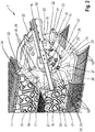
- a section of the reel 7 is shown in a perspective view.
- the reel 7 is connected to the cutting unit 4 by two support arms 14, of which only in Fig. 2 is shown.
- the reel 7 comprises a reel shaft 15, on which support stars 16 are arranged coaxially to one another at a uniform distance.
- a plurality of tine carriers 17, which extend continuously over the entire width of the reel 7, are arranged rotatably or pivotably about the circumference of the support stars 16.
- On these tine carriers 17, a plurality of conveying tines 18 are arranged evenly spaced apart, which are firmly connected to the respective tine carrier 17. So that the tine carriers 17 with the conveyor tines 18 rigidly attached to them pivot when the reel 7 rotates, the tine carriers 17 are embodied on a control star 19 Support star coupled.
- a control star 19 is mounted at the end on the outside of the reel shaft 15 facing the respective support arm 14.
- each tine carrier 17 and thus the orientation of the conveyor tines 18 attached to the respective tine carrier 17 is dependent on the instantaneous rotation angle or the instantaneous rotational position of the reel 7
- the control star 19 is assigned an adjusting device 20.
- the effectiveness of the conveying of the crop 8 is influenced by the conveyor tines 18.
- the adjusting device 20 comprises at least two cam track segments 21, which form a cam track structure for controlling the rotational position of the respective tine carrier 17.
- the cam track segments 21 are assigned to the control star 19 at a radial distance from the reel shaft 15.
- the cam track segments 21 are preferably designed as flat profiles. Materials such as plastic or metal, which can also be used in any combination, can be used to produce the curved track segments 21.
- the cam track structure is partially open in the circumferential direction, which is achieved by spacing 22 of the two cam track segments 21 at at least one point. In the exemplary embodiment shown, the cam track structure is interrupted at two points by a spacing 22 between the cam track segments 21, as in FIG Fig. 3 is shown.
- the cam track segments 21 are releasably attached to a cover plate 34, whose outline in Fig. 2 is shown in dashed lines.
- the cover plate 34 is detachably fastened on the side facing the respective support arms 14 coaxially to the reel shaft 15 on the cutting unit 4.
- crank arm 23 is rotatably arranged thereon.
- the crank arms 23 rotate together with the respective tine carrier 17 about an axis 24.
- a lever arrangement 25 engages at the free end of the respective crank arm 23.
- the lever assembly 25 includes cam track takers 28 which follow the course of the cam track structure predetermined by the shape of the cam track segments 22 and thereby transfer it to the lever arrangement 25.
- the inside 30 and outside 31 of the cam track segments 22 serve to guide the cam track takers 28 and thus to control the position of the conveyor tines 18.
- the lever arrangement 25 comprises a first lever arm 26 and a second lever arm 27.
- the first lever arm 26 extends essentially outward in the radial direction of the control star 19. With one end, the first lever arm 26 is pivoted on the crank arm 23. At its opposite end, the first lever arm 26 carries a pair of rollers 29 designed as cam track receptacles 28.
- the rollers 29 are arranged in the longitudinal direction of the first lever arm 26 so as to be diametrically rotatably mounted thereon about axes extending parallel to the reel shaft 15.
- the distance between the two rollers 29 on the first lever arm 26 is selected such that the two rollers 29 always roll on the inside 30 or on the outside 31 of the respective cam track segment 21 according to their positioning on the first lever arm 26.
- the second lever arm 27 of the respective lever arrangement 25 is pivoted at one end to the control star 19. Its other end is pivoted on the axis of the roller 29, which rolls on the outside 31 of the respective cam track segment 21.
- an inner guide element 32 and an outer guide element 33 are detachably arranged on the cover plate 34.
- the inner guide element 32 and the outer guide element 33 are arranged at a radial distance from the cam track segments 21.
- the radial distance is like this chosen that it is ensured that the two cam track takers 28 designed as rollers 29 are always in contact with the inner guide element 32 and the outer guide element 33 in the area of the spacing 22 between the cam track segments 21, in which the cam track takers 28 do not touch the cam track segments 21 stand until both rollers 29 again enclose the following cam track segment 21 between them in order to roll on it.
- the inner guide element 32 and the outer guide element 33 are also designed as a flat profile.
- the inner guide element 32 and the outer guide element 33 are shaped such that a movement corresponding to the course is transmitted to the crank arm 23 by the lever arrangement 25.
- Fig. 3 is a detailed view of the control star 19 and the adjusting device 20 arranged thereon of the reel 7 according to FIG Fig. 2 shown.
- the illustration essentially shows the cam track structure which is formed by the at least two cam track segments 21 which are detachably fastened to the cover plate 34 and the inner guide element 32 and the outer guide element 33.
- the lever arm arrangements 25, which rotate together with the control star 19, are arranged behind it.
- the rotational position of the tine carriers 17 and with these the conveyor tines 18 fastened thereon is determined by the sequence of movements impressed on the lever arrangement 25 by the curve segments 21.
- the curve segments 21 have different widths along their circumference, that is to say different expansions in the radial direction between the inside and the outside of the respective curve segment 21.
- the respective width of a curve segment 21 determines the degree of inclination of the first lever arm 26 during the rotation along the respective cam track segment 21.
- the change in inclination of the first lever arm 26 is caused by the crank arm 23 arranged at the end on the first lever arm 26 on the tine carrier 17 connected to it in a rotationally fixed manner transferred, whereby the conveyor tines 18 of a tine carrier 17 assume different orientation relative to the ground during one revolution.
- cam track segments 21 and the inner and outer guide elements 32, 33 on the cover plate 34 enables the track characteristics to be easily adapted to different harvesting conditions by exchanging one, preferably the lower, cam segment 21.
- this cam track structure is less maintenance-intensive than that according to FIG EP 1 297 735 B1 , since it dispenses with a channel clogged with crop, in which a curved track customer is guided.
Landscapes
- Life Sciences & Earth Sciences (AREA)
- Environmental Sciences (AREA)
- Outside Dividers And Delivering Mechanisms For Harvesters (AREA)
Claims (12)
- Équipement de ramassage de produit de récolte (5) comprenant au moins un rabatteur entraîné en rotation (7), qui comporte plusieurs étoiles porteuses (16) disposées à distance les unes des autres sur un arbre de rabatteur (15) ainsi que des barres porte-dents tournantes (17) qui s'étendent sur la largeur du rabatteur (7) et qui portent des dents d'alimentation (18), et comprenant un dispositif de réglage (20) par l'intermédiaire duquel la position de rotation des barres porte-dents (17) peut être réglée en fonction de la position de rotation du rabatteur (7), le dispositif de réglage (20) incluant une structure de came ouverte par endroits, constituée d'au moins deux segments de cames (21), au moyen de laquelle sont guidés des palpeurs de cames (28) commandant la position de rotation de la barre porte-dents (17), au moins un des segments de cames (21) étant monté de façon amovible, caractérisé en ce que les au moins deux segments de cames (21) présentent l'un par rapport à l'autre, dans la direction circonférentielle de la structure de came, au moins un intervalle (22) qui interrompt la structure de came.
- Équipement de ramassage de produit de récolte (5) selon la revendication 1, caractérisé en ce que les au moins deux segments de cames (21) sont conçus respectivement sous la forme d'un profilé plat, le côté intérieur (30) et le côté extérieur (31) du segment de came respectif (21) servant au guidage des palpeurs de cames (28).
- Équipement de ramassage de produit de récolte (5) selon la revendication 2, caractérisé en ce que le palpeur de came (28) circule sur le côté intérieur (30) du segment de came respectif (21) et l'autre palpeur de came (28) circule sur le côté extérieur (31) du segment de came respectif (21).
- Équipement de ramassage de produit de récolte (5) selon une des revendications 1 à 3, caractérisé en ce que dans la zone d'un intervalle (22) de deux segments de cames sont prévus des éléments de guidage intérieurs (32) et des éléments de guidage extérieurs (33) disposés respectivement par paires à distance radiale des segments de cames (21).
- Équipement de ramassage de produit de récolte (5) selon la revendication 4, caractérisé en ce que les éléments de guidage intérieurs (32) et les éléments de guidage extérieurs (33) présentent dans la direction circonférentielle une extension qui est supérieure à l'intervalle (22) entre deux segments de cames (21).
- Équipement de ramassage de produit de récolte (5) selon une des revendications 1 à 5, caractérisé en ce que les palpeurs de cames (28) sont disposés sur un agencement de leviers (25) qui est monté pivotant sur l'étoile porteuse (16).
- Équipement de ramassage de produit de récolte (5) selon la revendication 6, caractérisé en ce que l'agencement de leviers (25) comprend un premier bras de levier (26) qui est guidé le long des segments de cames (21) au moyen des palpeurs de cames (28) disposés sur celui-ci.
- Équipement de ramassage de produit de récolte (5) selon une des revendications 1 à 7, caractérisé en ce que les palpeurs de cames (28) sont conçus sous la forme de deux galets (29) qui, par rapport à l'orientation longitudinale de premier bras de levier (26), sont disposés diamétralement sur celui-ci.
- Équipement de ramassage de produit de récolte (5) selon la revendication 8, caractérisé en ce que l'un des galets (29) circule sur le côté intérieur (30) du segment de came respectif (21) et l'autre galet (29) circule sur le côté extérieur (31) du segment de came respectif (21).
- Équipement de ramassage de produit de récolte (5) selon une des revendications 6 à 9, caractérisé en ce que l'agencement de leviers (25) comprend un second bras de levier (26) qui est articulé de manière pivotante, par une extrémité, sur l'étoile de commande (19) et, par son autre extrémité, sur le premier bras de levier (26).
- Équipement de ramassage de produit de récolte (5) selon une des revendications 4 à 10, caractérisé en ce que l'intervalle radial des éléments de guidage intérieurs (32) et des éléments de guidage extérieurs (33) correspond au moins à l'écartement des galets disposés diamétralement (29).
- Équipement de ramassage de produit de récolte (5) selon une des revendications 6 à 11, caractérisé en ce qu'est prévue une manivelle (23) qui, par une extrémité, est articulée de manière pivotante sur une extrémité libre du premier bras de levier (26) et, par son autre extrémité, est solidarisé en rotation avec la barre porte-dents (17).
Applications Claiming Priority (1)
| Application Number | Priority Date | Filing Date | Title |
|---|---|---|---|
| DE102015112580.3A DE102015112580A1 (de) | 2015-07-31 | 2015-07-31 | Erntegutbergungseinrichtung |
Publications (2)
| Publication Number | Publication Date |
|---|---|
| EP3123855A1 EP3123855A1 (fr) | 2017-02-01 |
| EP3123855B1 true EP3123855B1 (fr) | 2020-01-15 |
Family
ID=56092827
Family Applications (1)
| Application Number | Title | Priority Date | Filing Date |
|---|---|---|---|
| EP16172062.8A Active EP3123855B1 (fr) | 2015-07-31 | 2016-05-31 | Tablier de coupe |
Country Status (3)
| Country | Link |
|---|---|
| EP (1) | EP3123855B1 (fr) |
| DE (1) | DE102015112580A1 (fr) |
| HU (1) | HUE048451T2 (fr) |
Families Citing this family (3)
| Publication number | Priority date | Publication date | Assignee | Title |
|---|---|---|---|---|
| CN108811709A (zh) * | 2018-08-02 | 2018-11-16 | 新疆农业大学 | 食葵捡拾割台 |
| CN108848874B (zh) * | 2018-08-20 | 2024-04-19 | 塔里木大学 | 一种绿肥翻压装置 |
| US11712004B2 (en) * | 2020-03-02 | 2023-08-01 | Cnh Industrial America Llc | Follower assembly of a cam assembly for a harvester reel |
Family Cites Families (6)
| Publication number | Priority date | Publication date | Assignee | Title |
|---|---|---|---|---|
| US5987861A (en) * | 1996-07-25 | 1999-11-23 | Duncan; Allister T. | Pea harvester |
| US6170244B1 (en) * | 1999-04-28 | 2001-01-09 | Deere & Company | Cam path for orientating fingers of a harvesting reel |
| US20020148210A1 (en) * | 2001-04-12 | 2002-10-17 | Hcc, Inc. | Harvester pickup reel |
| US6591598B2 (en) | 2001-10-01 | 2003-07-15 | Macdon Industries Ltd. | Crop harvesting header with cam controlled movement of the reel fingers |
| US8590284B2 (en) * | 2011-05-31 | 2013-11-26 | Cnh America Llc | Cam shield for a rotary reel |
| BR112015011184B1 (pt) * | 2012-12-21 | 2019-10-01 | Agco Corporation | Cabeçote de colheita de cultura para uso com uma máquina de ceifar agrícola" |
-
2015
- 2015-07-31 DE DE102015112580.3A patent/DE102015112580A1/de not_active Withdrawn
-
2016
- 2016-05-31 HU HUE16172062A patent/HUE048451T2/hu unknown
- 2016-05-31 EP EP16172062.8A patent/EP3123855B1/fr active Active
Non-Patent Citations (1)
| Title |
|---|
| None * |
Also Published As
| Publication number | Publication date |
|---|---|
| DE102015112580A1 (de) | 2017-02-02 |
| HUE048451T2 (hu) | 2020-07-28 |
| EP3123855A1 (fr) | 2017-02-01 |
Similar Documents
| Publication | Publication Date | Title |
|---|---|---|
| EP1048199B1 (fr) | Rabatteur pour machine de récolte | |
| DE2556688C2 (de) | Vorrichtung zum Aufnehmen und Weiterbefördern von Erntegut, insbesondere Getreide auf einer Erntemaschine, insbesondere einem Mähdrescher | |
| DE102013204977B4 (de) | Schneidwerk mit Querförderbändern und um die Hochachse schwenkbaren Förderwalzen | |
| EP0903077A1 (fr) | Ramasseur por recoltes | |
| EP2732689A1 (fr) | Barre de coupe | |
| EP2792622B1 (fr) | Procédé et dispositif de réorientation d'une tranche ou d'une portion d'un produit alimentaire découpé | |
| EP3123855B1 (fr) | Tablier de coupe | |
| EP2342967A1 (fr) | Récepteur de biens doté d'une protection d'enroulement | |
| DE102011013242B4 (de) | Ballenpresse | |
| EP2614698B1 (fr) | Faucheuse | |
| DE3033229A1 (de) | Erntevorrichtung fuer vorzugsweise in reihen angepflanztes erntegut mit vier foerderbahnen und einer leitvorrichtung | |
| EP1048200A1 (fr) | Rabatteur pour machine de récolte | |
| AT392194B (de) | Maschine zum ernten von mais od. dgl. stengelartigem erntegut | |
| DE102009017400A1 (de) | Erntemaschine | |
| DE3047878A1 (de) | Heuwerbungsmaschine | |
| EP3007540B1 (fr) | Dispositif à cueillir | |
| DE3217332A1 (de) | Maeh- und konditioniereinrichtung | |
| EP1776859A1 (fr) | Machine de récolte | |
| DE2262826A1 (de) | Maehwerkhaspel mit zinkensteuerung | |
| DE3000564A1 (de) | Heuwerbungsmaschine | |
| DE1934817B2 (de) | Heuwerbungsmaschine zum seitlichen zusammenrechen von erntegut | |
| EP3017683B1 (fr) | Râteau-faneur à bandes | |
| DE3033299C2 (de) | Antrieb für eine Schneidvorrichtung | |
| DE3324898C2 (fr) | ||
| EP3485718B1 (fr) | Faucheuse |
Legal Events
| Date | Code | Title | Description |
|---|---|---|---|
| PUAI | Public reference made under article 153(3) epc to a published international application that has entered the european phase |
Free format text: ORIGINAL CODE: 0009012 |
|
| STAA | Information on the status of an ep patent application or granted ep patent |
Free format text: STATUS: THE APPLICATION HAS BEEN PUBLISHED |
|
| AK | Designated contracting states |
Kind code of ref document: A1 Designated state(s): AL AT BE BG CH CY CZ DE DK EE ES FI FR GB GR HR HU IE IS IT LI LT LU LV MC MK MT NL NO PL PT RO RS SE SI SK SM TR |
|
| AX | Request for extension of the european patent |
Extension state: BA ME |
|
| STAA | Information on the status of an ep patent application or granted ep patent |
Free format text: STATUS: REQUEST FOR EXAMINATION WAS MADE |
|
| 17P | Request for examination filed |
Effective date: 20170801 |
|
| RBV | Designated contracting states (corrected) |
Designated state(s): AL AT BE BG CH CY CZ DE DK EE ES FI FR GB GR HR HU IE IS IT LI LT LU LV MC MK MT NL NO PL PT RO RS SE SI SK SM TR |
|
| GRAP | Despatch of communication of intention to grant a patent |
Free format text: ORIGINAL CODE: EPIDOSNIGR1 |
|
| STAA | Information on the status of an ep patent application or granted ep patent |
Free format text: STATUS: GRANT OF PATENT IS INTENDED |
|
| RAP1 | Party data changed (applicant data changed or rights of an application transferred) |
Owner name: CLAAS HUNGARIA KFT. |
|
| INTG | Intention to grant announced |
Effective date: 20191028 |
|
| GRAS | Grant fee paid |
Free format text: ORIGINAL CODE: EPIDOSNIGR3 |
|
| GRAA | (expected) grant |
Free format text: ORIGINAL CODE: 0009210 |
|
| STAA | Information on the status of an ep patent application or granted ep patent |
Free format text: STATUS: THE PATENT HAS BEEN GRANTED |
|
| AK | Designated contracting states |
Kind code of ref document: B1 Designated state(s): AL AT BE BG CH CY CZ DE DK EE ES FI FR GB GR HR HU IE IS IT LI LT LU LV MC MK MT NL NO PL PT RO RS SE SI SK SM TR |
|
| REG | Reference to a national code |
Ref country code: CH Ref legal event code: EP Ref country code: GB Ref legal event code: FG4D Free format text: NOT ENGLISH |
|
| REG | Reference to a national code |
Ref country code: IE Ref legal event code: FG4D Free format text: LANGUAGE OF EP DOCUMENT: GERMAN |
|
| REG | Reference to a national code |
Ref country code: DE Ref legal event code: R096 Ref document number: 502016008408 Country of ref document: DE |
|
| REG | Reference to a national code |
Ref country code: AT Ref legal event code: REF Ref document number: 1224361 Country of ref document: AT Kind code of ref document: T Effective date: 20200215 |
|
| REG | Reference to a national code |
Ref country code: NL Ref legal event code: MP Effective date: 20200115 |
|
| REG | Reference to a national code |
Ref country code: LT Ref legal event code: MG4D |
|
| REG | Reference to a national code |
Ref country code: HU Ref legal event code: AG4A Ref document number: E048451 Country of ref document: HU |
|
| PG25 | Lapsed in a contracting state [announced via postgrant information from national office to epo] |
Ref country code: NL Free format text: LAPSE BECAUSE OF FAILURE TO SUBMIT A TRANSLATION OF THE DESCRIPTION OR TO PAY THE FEE WITHIN THE PRESCRIBED TIME-LIMIT Effective date: 20200115 Ref country code: RS Free format text: LAPSE BECAUSE OF FAILURE TO SUBMIT A TRANSLATION OF THE DESCRIPTION OR TO PAY THE FEE WITHIN THE PRESCRIBED TIME-LIMIT Effective date: 20200115 Ref country code: PT Free format text: LAPSE BECAUSE OF FAILURE TO SUBMIT A TRANSLATION OF THE DESCRIPTION OR TO PAY THE FEE WITHIN THE PRESCRIBED TIME-LIMIT Effective date: 20200607 Ref country code: FI Free format text: LAPSE BECAUSE OF FAILURE TO SUBMIT A TRANSLATION OF THE DESCRIPTION OR TO PAY THE FEE WITHIN THE PRESCRIBED TIME-LIMIT Effective date: 20200115 Ref country code: NO Free format text: LAPSE BECAUSE OF FAILURE TO SUBMIT A TRANSLATION OF THE DESCRIPTION OR TO PAY THE FEE WITHIN THE PRESCRIBED TIME-LIMIT Effective date: 20200415 |
|
| PG25 | Lapsed in a contracting state [announced via postgrant information from national office to epo] |
Ref country code: SE Free format text: LAPSE BECAUSE OF FAILURE TO SUBMIT A TRANSLATION OF THE DESCRIPTION OR TO PAY THE FEE WITHIN THE PRESCRIBED TIME-LIMIT Effective date: 20200115 Ref country code: LV Free format text: LAPSE BECAUSE OF FAILURE TO SUBMIT A TRANSLATION OF THE DESCRIPTION OR TO PAY THE FEE WITHIN THE PRESCRIBED TIME-LIMIT Effective date: 20200115 Ref country code: BG Free format text: LAPSE BECAUSE OF FAILURE TO SUBMIT A TRANSLATION OF THE DESCRIPTION OR TO PAY THE FEE WITHIN THE PRESCRIBED TIME-LIMIT Effective date: 20200415 Ref country code: IS Free format text: LAPSE BECAUSE OF FAILURE TO SUBMIT A TRANSLATION OF THE DESCRIPTION OR TO PAY THE FEE WITHIN THE PRESCRIBED TIME-LIMIT Effective date: 20200515 Ref country code: HR Free format text: LAPSE BECAUSE OF FAILURE TO SUBMIT A TRANSLATION OF THE DESCRIPTION OR TO PAY THE FEE WITHIN THE PRESCRIBED TIME-LIMIT Effective date: 20200115 Ref country code: GR Free format text: LAPSE BECAUSE OF FAILURE TO SUBMIT A TRANSLATION OF THE DESCRIPTION OR TO PAY THE FEE WITHIN THE PRESCRIBED TIME-LIMIT Effective date: 20200416 |
|
| REG | Reference to a national code |
Ref country code: DE Ref legal event code: R097 Ref document number: 502016008408 Country of ref document: DE |
|
| PG25 | Lapsed in a contracting state [announced via postgrant information from national office to epo] |
Ref country code: SK Free format text: LAPSE BECAUSE OF FAILURE TO SUBMIT A TRANSLATION OF THE DESCRIPTION OR TO PAY THE FEE WITHIN THE PRESCRIBED TIME-LIMIT Effective date: 20200115 Ref country code: RO Free format text: LAPSE BECAUSE OF FAILURE TO SUBMIT A TRANSLATION OF THE DESCRIPTION OR TO PAY THE FEE WITHIN THE PRESCRIBED TIME-LIMIT Effective date: 20200115 Ref country code: SM Free format text: LAPSE BECAUSE OF FAILURE TO SUBMIT A TRANSLATION OF THE DESCRIPTION OR TO PAY THE FEE WITHIN THE PRESCRIBED TIME-LIMIT Effective date: 20200115 Ref country code: EE Free format text: LAPSE BECAUSE OF FAILURE TO SUBMIT A TRANSLATION OF THE DESCRIPTION OR TO PAY THE FEE WITHIN THE PRESCRIBED TIME-LIMIT Effective date: 20200115 Ref country code: DK Free format text: LAPSE BECAUSE OF FAILURE TO SUBMIT A TRANSLATION OF THE DESCRIPTION OR TO PAY THE FEE WITHIN THE PRESCRIBED TIME-LIMIT Effective date: 20200115 Ref country code: ES Free format text: LAPSE BECAUSE OF FAILURE TO SUBMIT A TRANSLATION OF THE DESCRIPTION OR TO PAY THE FEE WITHIN THE PRESCRIBED TIME-LIMIT Effective date: 20200115 Ref country code: CZ Free format text: LAPSE BECAUSE OF FAILURE TO SUBMIT A TRANSLATION OF THE DESCRIPTION OR TO PAY THE FEE WITHIN THE PRESCRIBED TIME-LIMIT Effective date: 20200115 Ref country code: LT Free format text: LAPSE BECAUSE OF FAILURE TO SUBMIT A TRANSLATION OF THE DESCRIPTION OR TO PAY THE FEE WITHIN THE PRESCRIBED TIME-LIMIT Effective date: 20200115 |
|
| PLBE | No opposition filed within time limit |
Free format text: ORIGINAL CODE: 0009261 |
|
| STAA | Information on the status of an ep patent application or granted ep patent |
Free format text: STATUS: NO OPPOSITION FILED WITHIN TIME LIMIT |
|
| 26N | No opposition filed |
Effective date: 20201016 |
|
| PG25 | Lapsed in a contracting state [announced via postgrant information from national office to epo] |
Ref country code: MC Free format text: LAPSE BECAUSE OF FAILURE TO SUBMIT A TRANSLATION OF THE DESCRIPTION OR TO PAY THE FEE WITHIN THE PRESCRIBED TIME-LIMIT Effective date: 20200115 Ref country code: IT Free format text: LAPSE BECAUSE OF FAILURE TO SUBMIT A TRANSLATION OF THE DESCRIPTION OR TO PAY THE FEE WITHIN THE PRESCRIBED TIME-LIMIT Effective date: 20200115 Ref country code: LI Free format text: LAPSE BECAUSE OF NON-PAYMENT OF DUE FEES Effective date: 20200531 Ref country code: CH Free format text: LAPSE BECAUSE OF NON-PAYMENT OF DUE FEES Effective date: 20200531 |
|
| PG25 | Lapsed in a contracting state [announced via postgrant information from national office to epo] |
Ref country code: SI Free format text: LAPSE BECAUSE OF FAILURE TO SUBMIT A TRANSLATION OF THE DESCRIPTION OR TO PAY THE FEE WITHIN THE PRESCRIBED TIME-LIMIT Effective date: 20200115 Ref country code: PL Free format text: LAPSE BECAUSE OF FAILURE TO SUBMIT A TRANSLATION OF THE DESCRIPTION OR TO PAY THE FEE WITHIN THE PRESCRIBED TIME-LIMIT Effective date: 20200115 |
|
| GBPC | Gb: european patent ceased through non-payment of renewal fee |
Effective date: 20200531 |
|
| PG25 | Lapsed in a contracting state [announced via postgrant information from national office to epo] |
Ref country code: LU Free format text: LAPSE BECAUSE OF NON-PAYMENT OF DUE FEES Effective date: 20200531 |
|
| PG25 | Lapsed in a contracting state [announced via postgrant information from national office to epo] |
Ref country code: IE Free format text: LAPSE BECAUSE OF NON-PAYMENT OF DUE FEES Effective date: 20200531 Ref country code: GB Free format text: LAPSE BECAUSE OF NON-PAYMENT OF DUE FEES Effective date: 20200531 |
|
| PG25 | Lapsed in a contracting state [announced via postgrant information from national office to epo] |
Ref country code: TR Free format text: LAPSE BECAUSE OF FAILURE TO SUBMIT A TRANSLATION OF THE DESCRIPTION OR TO PAY THE FEE WITHIN THE PRESCRIBED TIME-LIMIT Effective date: 20200115 Ref country code: MT Free format text: LAPSE BECAUSE OF FAILURE TO SUBMIT A TRANSLATION OF THE DESCRIPTION OR TO PAY THE FEE WITHIN THE PRESCRIBED TIME-LIMIT Effective date: 20200115 Ref country code: CY Free format text: LAPSE BECAUSE OF FAILURE TO SUBMIT A TRANSLATION OF THE DESCRIPTION OR TO PAY THE FEE WITHIN THE PRESCRIBED TIME-LIMIT Effective date: 20200115 |
|
| PG25 | Lapsed in a contracting state [announced via postgrant information from national office to epo] |
Ref country code: MK Free format text: LAPSE BECAUSE OF FAILURE TO SUBMIT A TRANSLATION OF THE DESCRIPTION OR TO PAY THE FEE WITHIN THE PRESCRIBED TIME-LIMIT Effective date: 20200115 Ref country code: AL Free format text: LAPSE BECAUSE OF FAILURE TO SUBMIT A TRANSLATION OF THE DESCRIPTION OR TO PAY THE FEE WITHIN THE PRESCRIBED TIME-LIMIT Effective date: 20200115 |
|
| REG | Reference to a national code |
Ref country code: AT Ref legal event code: MM01 Ref document number: 1224361 Country of ref document: AT Kind code of ref document: T Effective date: 20210531 |
|
| PG25 | Lapsed in a contracting state [announced via postgrant information from national office to epo] |
Ref country code: AT Free format text: LAPSE BECAUSE OF NON-PAYMENT OF DUE FEES Effective date: 20210531 |
|
| P01 | Opt-out of the competence of the unified patent court (upc) registered |
Effective date: 20230516 |
|
| PGFP | Annual fee paid to national office [announced via postgrant information from national office to epo] |
Ref country code: FR Payment date: 20230526 Year of fee payment: 8 Ref country code: DE Payment date: 20230519 Year of fee payment: 8 |
|
| PGFP | Annual fee paid to national office [announced via postgrant information from national office to epo] |
Ref country code: HU Payment date: 20230523 Year of fee payment: 8 |
|
| PGFP | Annual fee paid to national office [announced via postgrant information from national office to epo] |
Ref country code: BE Payment date: 20230519 Year of fee payment: 8 |