EP3122423B1 - Codierter statusindikator für automatisierte externe defibrillatoren - Google Patents
Codierter statusindikator für automatisierte externe defibrillatoren Download PDFInfo
- Publication number
- EP3122423B1 EP3122423B1 EP15708047.4A EP15708047A EP3122423B1 EP 3122423 B1 EP3122423 B1 EP 3122423B1 EP 15708047 A EP15708047 A EP 15708047A EP 3122423 B1 EP3122423 B1 EP 3122423B1
- Authority
- EP
- European Patent Office
- Prior art keywords
- test
- status
- status signal
- automated external
- external defibrillator
- Prior art date
- Legal status (The legal status is an assumption and is not a legal conclusion. Google has not performed a legal analysis and makes no representation as to the accuracy of the status listed.)
- Active
Links
- 238000012360 testing method Methods 0.000 claims description 91
- 230000000007 visual effect Effects 0.000 claims description 37
- 238000004891 communication Methods 0.000 claims description 5
- 238000000034 method Methods 0.000 claims description 5
- 230000003287 optical effect Effects 0.000 claims description 5
- 238000009434 installation Methods 0.000 claims description 2
- 230000003213 activating effect Effects 0.000 claims 2
- 208000032953 Device battery issue Diseases 0.000 claims 1
- 208000032368 Device malfunction Diseases 0.000 claims 1
- 229960003965 antiepileptics Drugs 0.000 description 45
- 230000035939 shock Effects 0.000 description 11
- 230000004397 blinking Effects 0.000 description 6
- 238000013194 cardioversion Methods 0.000 description 3
- 230000008901 benefit Effects 0.000 description 2
- 230000005540 biological transmission Effects 0.000 description 2
- 239000003990 capacitor Substances 0.000 description 2
- 230000000694 effects Effects 0.000 description 2
- 239000004973 liquid crystal related substance Substances 0.000 description 2
- 238000012423 maintenance Methods 0.000 description 2
- 230000007257 malfunction Effects 0.000 description 2
- 238000012986 modification Methods 0.000 description 2
- 230000004048 modification Effects 0.000 description 2
- 241000282412 Homo Species 0.000 description 1
- 230000004913 activation Effects 0.000 description 1
- 230000002051 biphasic effect Effects 0.000 description 1
- 239000008280 blood Substances 0.000 description 1
- 210000004369 blood Anatomy 0.000 description 1
- 230000008602 contraction Effects 0.000 description 1
- 230000001419 dependent effect Effects 0.000 description 1
- 230000007613 environmental effect Effects 0.000 description 1
- 230000006870 function Effects 0.000 description 1
- 238000002955 isolation Methods 0.000 description 1
- 230000000737 periodic effect Effects 0.000 description 1
- 238000012545 processing Methods 0.000 description 1
- 238000005086 pumping Methods 0.000 description 1
- 230000008439 repair process Effects 0.000 description 1
- 239000007787 solid Substances 0.000 description 1
- 238000013024 troubleshooting Methods 0.000 description 1
- 208000003663 ventricular fibrillation Diseases 0.000 description 1
Images

Classifications
-
- A—HUMAN NECESSITIES
- A61—MEDICAL OR VETERINARY SCIENCE; HYGIENE
- A61N—ELECTROTHERAPY; MAGNETOTHERAPY; RADIATION THERAPY; ULTRASOUND THERAPY
- A61N1/00—Electrotherapy; Circuits therefor
- A61N1/18—Applying electric currents by contact electrodes
- A61N1/32—Applying electric currents by contact electrodes alternating or intermittent currents
- A61N1/38—Applying electric currents by contact electrodes alternating or intermittent currents for producing shock effects
- A61N1/39—Heart defibrillators
- A61N1/3904—External heart defibrillators [EHD]
-
- A—HUMAN NECESSITIES
- A61—MEDICAL OR VETERINARY SCIENCE; HYGIENE
- A61N—ELECTROTHERAPY; MAGNETOTHERAPY; RADIATION THERAPY; ULTRASOUND THERAPY
- A61N1/00—Electrotherapy; Circuits therefor
- A61N1/18—Applying electric currents by contact electrodes
- A61N1/32—Applying electric currents by contact electrodes alternating or intermittent currents
- A61N1/38—Applying electric currents by contact electrodes alternating or intermittent currents for producing shock effects
- A61N1/39—Heart defibrillators
- A61N1/3925—Monitoring; Protecting
-
- A—HUMAN NECESSITIES
- A61—MEDICAL OR VETERINARY SCIENCE; HYGIENE
- A61N—ELECTROTHERAPY; MAGNETOTHERAPY; RADIATION THERAPY; ULTRASOUND THERAPY
- A61N1/00—Electrotherapy; Circuits therefor
- A61N1/18—Applying electric currents by contact electrodes
- A61N1/32—Applying electric currents by contact electrodes alternating or intermittent currents
- A61N1/38—Applying electric currents by contact electrodes alternating or intermittent currents for producing shock effects
- A61N1/39—Heart defibrillators
- A61N1/3993—User interfaces for automatic external defibrillators
-
- A—HUMAN NECESSITIES
- A61—MEDICAL OR VETERINARY SCIENCE; HYGIENE
- A61N—ELECTROTHERAPY; MAGNETOTHERAPY; RADIATION THERAPY; ULTRASOUND THERAPY
- A61N1/00—Electrotherapy; Circuits therefor
- A61N1/02—Details
- A61N1/04—Electrodes
- A61N1/0404—Electrodes for external use
- A61N1/0408—Use-related aspects
- A61N1/046—Specially adapted for shock therapy, e.g. defibrillation
Definitions
- the present invention generally relates to automated external defibrillators ("AED").
- AED automated external defibrillators
- the present invention specifically relates to a status indicator emitting an encoded status light including a base status of an operational readiness of the automated external defibrillator and a test status of self-test information of the automated external defibrillator.
- an AED may employ a ready light, for example a green light emitting diode (LED) to emit a visual indication of an operational readiness of the AED (i.e., a visual base status of the AED).
- the ready light may be blinking to visually indicate a standby mode of the AED whereby the AED is ready for use, or may be a solid color to visually indicate that the AED is in a use mode of operation, or may be blinking in a different color and rate to visually indicate that the AED has failed a self-test and is need of attention (e.g., operational malfunction, temperature issue, improper pad cartridge installation or low battery power).
- the ready light may also be turned completely off to indicate a complete failure of the AED.
- an AED may employ an information button to access a visual indication of self-test information in detail of the AED (i.e., a visual test status of the AED).
- the AED may flash its information button in optional conjunction with an audible indication of a need to troubleshoot the AED, whereby a pressing of the flashing information button displays detailed troubleshooting instructions and recommendations for the AED.
- LCD liquid crystal displays
- U.S. Patent 5,879,374 entitled “External defibrillator with automatic self-testing prior to use”.
- the AED controls such LCD displays to create a graphic, to obscure a portion of a backplane graphic, or to operate an LCD backlight in order to convey readiness information.
- Such an AED has a failsafe display in that a failed indication is shown on the backplane graphic even in the result of a complete loss of power.
- WO-A-2006/102427 and US-A-2011/213433 disclose automated external defibrillators.
- AEDs convey only limited information about the AED operational status, and only to viewers within visual range of the display.
- Some AEDs are arranged to transmit readiness status by alternate wireless means in parallel with the display, but such features add cost and complexity to the AED, and reduce its battery life. What is needed is a simpler means of transmitting readiness status of an AED without additional cost or power usage.
- the present invention solves the prior art problem with an AED that operates to concurrently communicate basic operational readiness and self-test information of the AED in the display, as well as more detailed machine-readable status information encoded within the same display. Much more information can thus be conveyed from a single status indicator.
- the present invention provides an intensity modulation of an encoded status light to concurrently visually indicate the base status and the test status of the AED respectively to an operator/technician and to a technician device (e.g., any type of smart handheld computer or mobile device).
- the present invention provides an automated external defibrillator according to claim 1, a system according to claim 11 and a method for displaying the status of an automated external defibrillator according to claim 14.
- One form of the present invention is an automated external defibrillator employing a self-test circuit and an encoded status indicator (e.g., an encoder and a light source preferably in the form of a light emitting diode).
- the self-test circuit automatically tests the automated external defibrillator and, dependent upon the outcome of the test, generates both a base status indicative of an operational readiness of the automated external defibrillator and a test status indicative of self-test information of the automated external defibrillator.
- the encoded status indicator concurrently visually indicates both the base status and the test status with the visual indication of the base status being perceivable to a human eye and the visual indication of the test status being in a form that is not perceivable to the human eye.
- a second form of the present invention is a system employing the aforementioned automated external defibrillator and further employing a technician (e.g., a smart handheld computer or mobile device) having a light detector operable to visually detect the encoded test status information.
- the technician further interprets the encoded status information, displays the information, and optionally conveys the information to a remote location via a wireless transmission.
- exemplary embodiments of the present invention will be provided herein directed to variety of intensity modulations of an encoded status indicator for concurrently visually indicating a base status and a test status of an AED.
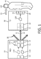
- an AED 10 of the present invention comprises a self-test circuit 11 that preferably operates on an automatic and periodic basis to test critical components of the AED while it is in a standby condition.
- the self-test circuit 11 issues a base status signal 110 which indicates an operational readiness of the AED.
- operational readiness is "ready”, i.e. ready for use whereupon all critical sub-systems have passed system testing.
- Another example of operational readiness is "caution”, i.e. can be used but should be checked., and "failure”, i.e. should be removed from service for repair or maintenance.
- Another example of operational readiness is "failure”, i.e. the AED should not be used until the failure is corrected.
- the self-test circuit 11 issues a test status signal 120 which indicates further self-test information of the AED (10).
- the self-test information is preferably more detailed information, and is also preferably related to the operational readiness information in some way.
- the self-test information that is issued with a "ready" operational status signal could be routine data concerning past use, such as the elapsed time in days since the AED was last handled, e.g. when an AED button was last pressed, or when the electrodes or battery were last replaced.
- Self-test information that is issued with a "caution” operational status could be issued for an environmental temperature above or below the device specification.
- self-test information that is issued with a "failure” operational status could be the failure type, such as a low battery condition, and electrode pads failure, or a device system malfunction.
- the self-test circuit 11 simultaneously generates both of the base status signal 110 and the test status signal 120.
- the signals are in turn received as data inputs by an encoder 13.
- Encoder 13 combines the base status and test status signals 110,120 into a single encoded status signal 130. Embodiments of the single encoded status signal 130 are described in more detail below.
- AED 10 further comprises an encoded status indicator which visually displays the single encoded status signal 130.
- the encoded status indicator includes a light source 14, such as a light emitting diode (LED).
- the encoder or the encoded status indicator modulates the intensity of light source 14 in a pattern that is a function of, and indicative of, the single encoded status signal.
- the single encoded status signal comprises two portions. A first portion is a visual indication 21 of the base status signal 110 indicative of the operational readiness. A second portion is a visual indication 22 of the test status signal 120 indicative of the self-test information.
- Visual indication 21 is arranged in the pattern that can be perceived by an observer 40 as an operational status signal 110.
- visual indication 21 appears as a blinking or flashing light in a pattern known in the art as indicating "ready”, “caution”, or “failure”. Such blinking can also be generated from different colored LED lights in order to distinguish the operational status' more clearly.
- Visual indication 22 is preferably arranged in a pattern that is optimized to convey a maximum of information within about the time of a single blink or flash of visual indication 21.
- light source 15 may be modulated at a rate high enough to be imperceptible to an observer.
- visual indication 21 may be perceived easily at a pulse length of 1 millisecond
- visual indication 22 may be modulated at a frequency of 50 microseconds, which is not perceptible to humans.
- the pattern of flashes, e.g. twenty possible events, obtainable by visual indication 22 within the 1 millisecond period of visual indication 21 may be sufficient to convey a fault code or other information related to the test status signal. If even more information is to be conveyed, visual indication 22 may be parsed among several adjacent time periods of visual indication 21.
- FIGURE 1 further illustrates a technician device 30, which may be a stand-alone device or an off-the-shelf mobile smart phone or handheld computer with a software application particular to the invention.
- Technician device 30 includes an optical detector 31 operable to detect visual indication 22 of test status signal 120 and converts the signal into electrical form.
- Technician device 30 further includes a decoder 32 in communication with optical detector 31 which decodes test status signal 120 and passes an output the user. The output is preferably a display 33 to display the decoded test status signal 120.
- a speaker 34 may be employed to audibilize the decoded test status signal 120.
- Technician 30 may also be arranged to wirelessly transmit data pertaining to the test status signal 120 to a remote maintenance location.
- AED 10 intensity-modulates light source 14 to emit a status light 20 in a manner whereby a human-perceiveable operational status pattern is combined with a self test status pattern that is flashing at a frequency unperceivable to the eye.
- the highfrequency and short duration flashing pattern is arranged to be detectable by technician device 30.
- FIGURE 2A illustrates an embodiment wherein a visual indication of test status 22a is modulated within a solid-on state 21a of visual indication 21.
- the pattern of test status 22a can be pre-determined to be indicative of a particular test status.
- the FIGURE 2A embodiment can thus be modulated to provide an entire set of test status data in a single uninterrupted stream.
- FIGURE 2B illustrates a second example, wherein the visual indication 21 is in a blinking state 21b.
- test status 22b as a whole provides the entire "on" cycle of the blinking state 21b of perceivable visual indication 21.
- the on-length of visual indication 21 is too short to convey all of the data of test status 22b, remaining data can be modulated onto the next flash of visual indication 21.
- modulated signals 22a and 22b show no particular data pattern, it is understood that patterns as known in the optical data transmission art may be employed to convey different types of information.
- a pattern 21c of visual indication 21 has an "on" cycle that is perceivable by the eye of the viewer 40.
- pattern pulses 22c of visual indication 22 are output from light source 14 at a frequency detectable only by technician device 30. Thus, the viewer perceives only visual indication 21.
- pulses 22c of visual indication 22 are output during an "off' cycle of wave form 21c at a frequency that is detectable only by technician device 30.
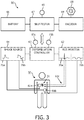
- an AED 60 of the present invention employs a pair of electrode pads or paddles 61a and 61b, optional ECG leads 61c, a ECG monitor 62 (internal or external), a defibrillation controller 63, a shock source 64, operator buttons 65, a battery 66, a self-test circuit 67, an encoder 68 and a light source 69.
- Electrode pads/paddles 61a and 61b are structurally configured as known in the art to be conductively applied to a patient 50 in an anterior-apex arrangement as shown in FIGURE 3 , or in an anterior-posterior arrangement (not shown). Electrode pad/paddles 61a and 61b conduct a defibrillation shock from shock source 64 to a heart 51 of patient 50 and conduct an ECG signal (not shown) representative of electrical activity of heart 51 of patient 50 to ECG monitor 62. Alternatively or concurrently, ECG leads 61c are connected to patient 50 as known in the art to conduct the ECG signal to ECG monitor 62.
- ECG monitor 62 is structurally configured as known in the art for processing the ECG signal to measure the electrical activity of heart 51 of patient 50 as an indication patient 50 is experiencing an organized heartbeat condition or an unorganized heartbeat condition.
- An example of the ECG signal indicating an organized heartbeat condition is an ECG waveform 70a that is representative of an organized contraction of the ventricles of heart 51 of patient 50 being capable of pumping blood.
- An example of the ECG signal indicating an unorganized heartbeat condition is an ECG waveform 70b that is representative of a ventricular fibrillation of heart 51 of patient 50.
- Shock source 64 is structurally configured as known in the art to store electric energy for delivery of a defibrillation shock 71 via electrode pads/paddles 61a and 61b to heart 51 of patient 50 as controlled by defibrillation controller 63.
- defibrillation shock 71 may have any waveform as known in the art. Examples of such waveforms include, but are not limited to, a monophasic sinusoidal waveform (positive sine wave) 71a and a biphasic truncated waveform 71b as shown in FIGURE 3 .
- shock source 64 employs a high voltage capacitor bank (not shown) for storing a high voltage via a high voltage charger and a power supply upon a pressing of an optional charge button 65b. Shock source 64 further employs a switching/isolation circuit (not shown) for selectively applying a specific waveform of an electric energy charge from the high voltage capacitor bank to electrode pads/paddles 61a and 61b as controlled by defibrillation controller 63.
- Defibrillation controller 63 is structurally configured as known in the art to execute a manual cardioversion via a shock button 65c and/or an automatic cardioversion.
- defibrillation controller 63 employs hardware/circuitry (e.g., processor(s), memory, etc.) for executing a manual and/or an automatic cardioversion installed as software/firmware within defibrillation controller 63.
- Disposable battery 66 is structurally configured as known in the art the charging various components of AED 60 as shown and not shown (e.g., a power supply).
- Self-test circuit 67 is structurally configured as known in the art to execute operational testing of various components of AED 60, particularly electrode pads/paddles 61a and 61b, ECG leads 61c, ECG monitor 62, defibrillation controller 63, shock source 64 and battery 66.
- AED 60 includes a user-operated information button 65.
- Self-test circuit 67 activates the information button 65 when a self test status information is generated. The activation may be accompanied by another flashing light or an annunciator to indicate that information is available. When a user then presses the information button 65, the self-test circuit 67 audibly communicates the test status via a speaker (not shown).
- Encoder 68 is structurally configured as would be appreciated by those skilled in the art to execute an intensity modulation of a status light as emitted by light source 69 (e.g., a light emitting diode) in accordance with an indication protocol of AED 60 to concurrently visually indicate the base status and test status of AED 60 as previously described herein.
- light source 69 e.g., a light emitting diode
- the ready light may be encoded in accordance with the present invention to concurrently visually indicate the operational readiness and the self-test information of the AED.
- the ready light may be encoded in accordance with the present invention to concurrently visually indicate the operational readiness and the self-test information of the AED.
- the encoded status indicator may employ a liquid crystal display (LCD) instead of an LED.
- the LCD may be operated in a pattern which conveys similar test signal information at a frequency higher than that perceptible by the viewer, but perceptible to a technician device 30.
- the LCD pattern(s) may also be placed into the LCD backlight instead of into the LCD shutter.
Claims (15)
- Automatisierter externer Defibrillator (10), umfassend:eine Selbsttestschaltung (11), die betätigt werden kann, um den automatisierten externen Defibrillator (10) automatisch und periodisch zu testen, und ferner betreibbar ist, um sowohl ein Basisstatussignal (110) zu erzeugen, das eine Betriebsbereitschaft des automatisierten externen Defibrillators (10) anzeigt, als auch einen Teststatussignal (120), das Selbsttestinformationen des automatisierten externen Defibrillators (10) anzeigt;einen Codierer (13), der funktionsfähig mit der Selbsttestschaltung (11) verbunden und betreibbar ist, um das Basisstatussignal und das Teststatussignal zu einem einzigen codierten Statussignal zu kombinieren; undeine codierte Statusanzeige in Kommunikation mit dem Codierer, die betreibbar ist, um das einzelne codierte Statussignal visuell anzuzeigen;wobei der Teil des angezeigten einfach codierten Statussignals, der das Basisstatussignal darstellt, so angeordnet ist, dass er vom Menschen wahrgenommen werden kann, undwobei der Teil des angezeigten einfach codierten Statussignals, der das Teststatussignal darstellt, so angeordnet ist, dass er maschinenlesbar ist und dadurch gekennzeichnet ist, dass der Teil des angezeigten einfach codierten Statussignals, der das Teststatussignal darstellt, so angeordnet ist, dass er für das menschliche Auge nicht wahrnehmbar ist.
- Automatisierter externer Defibrillator (10) nach Anspruch 1, wobei der codierte Statusindikator umfasst:eine Lichtquelle (14) zum Aussenden eines Statuslichts (20),wobei der Codierer die Lichtquelle steuert, um das Statuslicht (20), wie es von der Lichtquelle (14) emittiert wird, als Funktion des einfach codierten Statussignals intensitätsmoduliert, gegebenenfalls wobei die Lichtquelle (14) eine Leuchtdiode ist.
- Automatisierter externer Defibrillator (10) nach Anspruch 1, wobei die Selbsttestinformationen in dem Teststatussignal (120) mit der Betriebsbereitschaft des Basisstatussignals (110) zusammenhängen.
- Automatisierter externer Defibrillator (10) nach Anspruch 3, wobei die Betriebsbereitschaft ein Fehlerstatus ist und die Selbsttestinformation aus einem niedrigen Batterieausfall, einem Ausfall der Elektrodenpads und einem Ausfall der Gerätefehlfunktion besteht.
- Automatisierter externer Defibrillator (10) nach Anspruch 3, wobei die Betriebsbereitschaft ein Warnstatus ist und die Selbsttestinformation ein Niedertemperaturzustand ist.
- Automatisierter externer Defibrillator (10) nach Anspruch 3, wobei die Betriebsbereitschaft ein Bereitschaftsstatus ist und die Selbsttestinformation aus einer verstrichenen Zeit seit einem letzten erfassten Tastendruck und einer verstrichenen Zeit seit einer letzten Installation der Elektrodenpads besteht.
- Automatisierter externer Defibrillator (10) nach Anspruch 1, ferner umfassend:eine vom Benutzer betätigte Informationstaste (65),wobei die Selbsttestschaltung (11) den Teststatus (112) als Reaktion auf eine Betätigung der vom Benutzer betätigten Informationstaste (65) hörbar kommuniziert.
- Automatisierter externer Defibrillator nach Anspruch 1, umfassend eine Anzeige zum Anzeigen des Bereitschaftsstatus des automatisierten Defibrillators, wobei die Anzeige umfasst:erste und zweite Dateneingabe in Bezug auf die jeweilige Betriebsbereitschaft und den Selbstteststatus des automatisierten externen Defibrillators;der Codierer (13), der betreibbar ist, um ein einzelnes codiertes Statussignal aus dem ersten und dem zweiten Dateneingang zu erzeugen; undeine visuelle Anzeige des codierten Statussignals, die ein blinkendes Licht umfasst, das in einem Muster moduliert ist, das sowohl die Betriebsbereitschaft als auch den Selbstteststatus des automatisierten externen Defibrillators anzeigt.
- Automatisierter externer Defibrillator nach Anspruch 1, wobei das codierte Statussignal ein Selbsttest-Statusmuster umfasst, das nacheinander mit einem Betriebsbereitschaftsmuster ausgegeben wird.
- Automatisierter externer Defibrillator nach Anspruch 1, wobei das codierte Statussignal ein Selbsttest-Statusmuster umfasst, das gleichzeitig mit einem Betriebsbereitschaftsmuster ausgegeben wird.
- System, umfassend:einen automatisierten externen Defibrillator (10) nach Anspruch 1; undeine Technikervorrichtung (30) mit einem optischen Detektor (31), der zur Erfassung der visuellen Anzeige des Teststatussignals (120) betreibbar ist.
- System nach Anspruch 11, wobei die Technikervorrichtung (30) ferner umfasst:
einen Decodierer (32), der mit dem optischen Detektor (31) in Verbindung steht, um das Teststatussignal (120) zu decodieren. - System nach Anspruch 12, wobei die Technikervorrichtung (30) ferner umfasst:
eine Anzeige (33) in Kommunikation mit dem Decodierer (32) zur visuellen Anzeige des decodierten Teststatussignals (120) und/oder ein Lautsprecher (34) in Kommunikation mit dem Decodierer (32) zur akustischen Kommunikation des decodierten Teststatussignals (120). - Verfahren zum Anzeigen des Status eines automatisierten externen Defibrillators (10), wobei das Verfahren umfasst:Bereitstellen einer Selbsttestschaltung (11) in dem automatisierten externen Defibrillator (10);automatisches Erzeugen sowohl eines Basisstatussignals (110), das eine Betriebsbereitschaft des automatisierten externen Defibrillators (10) anzeigt, als auch eines Teststatussignals (120), das Selbsttestinformationen des automatisierten externen Defibrillators (10) anzeigt; undBetreiben einer codierten Statusanzeige des automatisierten externen Defibrillators (10), um gleichzeitig sowohl das Basisstatussignal (110) als auch das Teststatussignal (120) auf einer einzigen Anzeige visuell anzuzeigen;wobei die visuelle Anzeige des Basisstatus (110) für ein menschliches Auge wahrnehmbar ist, unddadurch gekennzeichnet, dassdie visuelle Anzeige des Teststatus (120) für das menschliche Auge nicht wahrnehmbar ist.
- Verfahren nach Anspruch 14, ferner umfassend:Aktivieren einer vom Benutzer betätigten Informationstaste (65); undakustische Anzeige der Selbsttestinformationen, die auf den Aktivierungsschritt reagieren.
Applications Claiming Priority (2)
| Application Number | Priority Date | Filing Date | Title |
|---|---|---|---|
| US201461971310P | 2014-03-27 | 2014-03-27 | |
| PCT/IB2015/050836 WO2015145272A1 (en) | 2014-03-27 | 2015-02-04 | Encoded status indicator for automated external defibrilators |
Publications (2)
| Publication Number | Publication Date |
|---|---|
| EP3122423A1 EP3122423A1 (de) | 2017-02-01 |
| EP3122423B1 true EP3122423B1 (de) | 2021-06-16 |
Family
ID=52627537
Family Applications (1)
| Application Number | Title | Priority Date | Filing Date |
|---|---|---|---|
| EP15708047.4A Active EP3122423B1 (de) | 2014-03-27 | 2015-02-04 | Codierter statusindikator für automatisierte externe defibrillatoren |
Country Status (6)
| Country | Link |
|---|---|
| US (1) | US10449379B2 (de) |
| EP (1) | EP3122423B1 (de) |
| JP (2) | JP6517230B2 (de) |
| CN (1) | CN106132480B (de) |
| RU (1) | RU2685739C2 (de) |
| WO (1) | WO2015145272A1 (de) |
Families Citing this family (12)
| Publication number | Priority date | Publication date | Assignee | Title |
|---|---|---|---|---|
| EP3122423B1 (de) * | 2014-03-27 | 2021-06-16 | Koninklijke Philips N.V. | Codierter statusindikator für automatisierte externe defibrillatoren |
| EP3240608B1 (de) * | 2014-12-30 | 2019-11-20 | Koninklijke Philips N.V. | Anzeiger von erweiterter warnung für medizinische notfallvorrichtungen |
| WO2017121718A1 (en) * | 2016-01-11 | 2017-07-20 | Koninklijke Philips N.V. | Method and apparatus for non-audible sensing of a defibrillator status indicator |
| CN107831418A (zh) * | 2017-10-27 | 2018-03-23 | 深圳迈瑞生物医疗电子股份有限公司 | 检测除颤仪的方法、系统和除颤仪 |
| GB201721767D0 (en) * | 2017-12-22 | 2018-02-07 | Heartsine Tech Limited | Defibrillator status indication and activation |
| US11452881B2 (en) | 2019-01-03 | 2022-09-27 | Avive Solutions, Inc. | Defibrillator communications architecture |
| JP7194846B2 (ja) | 2019-04-18 | 2022-12-22 | シグニファイ ホールディング ビー ヴィ | 照明デバイス |
| US20210384979A1 (en) * | 2020-06-03 | 2021-12-09 | Telefonaktiebolaget Lm Ericsson (Publ) | Information communication using equipment indicator lights |
| JP7418289B2 (ja) * | 2020-06-05 | 2024-01-19 | 日本光電工業株式会社 | 自動体外式除細動器、及び自動体外式除細動器の状態表示方法 |
| AU2021338777A1 (en) * | 2020-09-11 | 2023-05-04 | Ventis Medical, Inc. | System and methods of administering a status check to a medical device |
| US11865352B2 (en) | 2020-09-30 | 2024-01-09 | Zoll Medical Corporation | Remote monitoring devices and related methods and systems with audible AED signal listening |
| GB2620944A (en) * | 2022-07-26 | 2024-01-31 | Pitpatpet Ltd | System and method for testing a device on production line |
Family Cites Families (24)
| Publication number | Priority date | Publication date | Assignee | Title |
|---|---|---|---|---|
| JPH03121740U (de) * | 1990-03-23 | 1991-12-12 | ||
| US5285792A (en) * | 1992-01-10 | 1994-02-15 | Physio-Control Corporation | System for producing prioritized alarm messages in a medical instrument |
| US5879374A (en) | 1993-05-18 | 1999-03-09 | Heartstream, Inc. | External defibrillator with automatic self-testing prior to use |
| FR2719113B1 (fr) | 1994-04-26 | 1996-07-12 | Auxitrol Sa | Capteur de niveau de liquide à noyau plongeur. |
| JPH10215491A (ja) * | 1997-01-29 | 1998-08-11 | Matsushita Electric Ind Co Ltd | 電子機器の状態解析方法および電子機器状態解析装置 |
| US5904707A (en) * | 1997-08-15 | 1999-05-18 | Heartstream, Inc. | Environment-response method for maintaining an external medical device |
| DE60135422D1 (de) * | 2000-03-03 | 2008-10-02 | Koninkl Philips Electronics Nv | Verfahren und vorrichtung zur datenübertragung von einem gerät zum anderen |
| US7384886B2 (en) * | 2004-02-20 | 2008-06-10 | Chevron Phillips Chemical Company Lp | Methods of preparation of an olefin oligomerization catalyst |
| US9008767B2 (en) * | 2004-11-18 | 2015-04-14 | Scion Medical Limited | System and method for performing self-test in an automatic external defribillator (AED) |
| WO2006102427A2 (en) * | 2005-03-21 | 2006-09-28 | Defibtech, Llc | System and method for presenting defibrillator status information while in standby mode |
| US8116863B2 (en) | 2006-03-21 | 2012-02-14 | Defibtech, Llc | System and method for effectively indicating element failure or a preventive maintenance condition in an automatic external defibrillator (AED) |
| BRPI0718623B1 (pt) | 2006-11-14 | 2019-03-26 | Koninklijke Philips N.V. | Sistema de terapia de ressuscitação cardiopulmonar |
| CN101969842B (zh) * | 2008-01-14 | 2012-12-05 | 皇家飞利浦电子股份有限公司 | 房颤监测 |
| WO2010007574A1 (en) | 2008-07-18 | 2010-01-21 | Koninklijke Philips Electronics N.V. | Drug delivery system with a fastening band |
| WO2010007589A1 (en) | 2008-07-18 | 2010-01-21 | Koninklijke Philips Electronics N.V. | Medical device and method for monitoring status information |
| JP2010098078A (ja) * | 2008-10-15 | 2010-04-30 | Tokyo Electric Power Co Inc:The | 太陽光発電システムの状態監視装置およびコンピュータプログラム |
| CN102388676B (zh) | 2009-04-08 | 2016-11-09 | 皇家飞利浦电子股份有限公司 | 通过已调制光进行状态指示的照明设备 |
| RU2556969C2 (ru) * | 2009-09-28 | 2015-07-20 | Конинклейке Филипс Электроникс Н.В. | Дефибриллятор с предварительно подсоединенными электродными накладками со сниженной восприимчивостью к ошибочным выявлениям асистолии |
| JP3156737U (ja) * | 2009-10-29 | 2010-01-14 | 弘明 小平 | 自動体外式除細動器収納装置 |
| JP5804490B2 (ja) * | 2011-02-21 | 2015-11-04 | 日本電気通信システム株式会社 | 車両の故障診断システムにおける電子制御装置および故障診断情報送信方法 |
| JP5536703B2 (ja) * | 2011-03-31 | 2014-07-02 | 株式会社日立システムズ | 自動体外式除細動器監視・探索システム、自動体外式除細動器誘導システム及び自動体外式除細動器監視センタ並びに自動体外式除細動器監視方法 |
| WO2013128308A1 (en) * | 2012-02-28 | 2013-09-06 | Koninklijke Philips N.V. | Single use aed |
| US9730293B2 (en) | 2013-07-02 | 2017-08-08 | Philips Lighting Holding B.V. | Method and apparatus for conveying aggregate presence information using light |
| EP3122423B1 (de) * | 2014-03-27 | 2021-06-16 | Koninklijke Philips N.V. | Codierter statusindikator für automatisierte externe defibrillatoren |
-
2015
- 2015-02-04 EP EP15708047.4A patent/EP3122423B1/de active Active
- 2015-02-04 RU RU2016142323A patent/RU2685739C2/ru not_active IP Right Cessation
- 2015-02-04 US US15/128,800 patent/US10449379B2/en active Active
- 2015-02-04 JP JP2016558702A patent/JP6517230B2/ja active Active
- 2015-02-04 CN CN201580016589.7A patent/CN106132480B/zh active Active
- 2015-02-04 WO PCT/IB2015/050836 patent/WO2015145272A1/en active Application Filing
-
2019
- 2019-04-17 JP JP2019078227A patent/JP7019625B2/ja active Active
Non-Patent Citations (1)
| Title |
|---|
| None * |
Also Published As
| Publication number | Publication date |
|---|---|
| JP7019625B2 (ja) | 2022-02-15 |
| RU2016142323A3 (de) | 2018-09-11 |
| WO2015145272A1 (en) | 2015-10-01 |
| JP2017508558A (ja) | 2017-03-30 |
| CN106132480B (zh) | 2019-11-05 |
| US10449379B2 (en) | 2019-10-22 |
| CN106132480A (zh) | 2016-11-16 |
| RU2685739C2 (ru) | 2019-04-23 |
| RU2016142323A (ru) | 2018-04-28 |
| EP3122423A1 (de) | 2017-02-01 |
| JP2019130389A (ja) | 2019-08-08 |
| US20180214706A1 (en) | 2018-08-02 |
| JP6517230B2 (ja) | 2019-05-22 |
Similar Documents
| Publication | Publication Date | Title |
|---|---|---|
| EP3122423B1 (de) | Codierter statusindikator für automatisierte externe defibrillatoren | |
| JP6517396B2 (ja) | 医用デバイスの適応セルフテスト及びストレス解析 | |
| US11145409B2 (en) | Single use AED | |
| US20210387012A1 (en) | Automated external defibrillator systems and methods of use | |
| WO2009034506A1 (en) | Remote status indicator for a defibrillator | |
| US20060036914A1 (en) | Hazard mitigation in medical device | |
| CN105999553A (zh) | 具有多患者无线监测能力的自动体外除颤器(aed)系统 | |
| JP2017508558A5 (de) | ||
| RU2661023C2 (ru) | Интуитивно-понятный индикатор готовности с перекрыванием для дефибрилляторов | |
| US20150094782A1 (en) | Electrode with feature for indicating prior use with adult or pediatric subject and systems and methods including same | |
| US20220257961A1 (en) | Automated External Defibrillator and Power Supply Adapted for Non-Clinical Use | |
| US20230285763A1 (en) | Automated external defibrillator and method for notification about abnormality of automated external defibrillator |
Legal Events
| Date | Code | Title | Description |
|---|---|---|---|
| STAA | Information on the status of an ep patent application or granted ep patent |
Free format text: STATUS: THE INTERNATIONAL PUBLICATION HAS BEEN MADE |
|
| PUAI | Public reference made under article 153(3) epc to a published international application that has entered the european phase |
Free format text: ORIGINAL CODE: 0009012 |
|
| STAA | Information on the status of an ep patent application or granted ep patent |
Free format text: STATUS: REQUEST FOR EXAMINATION WAS MADE |
|
| 17P | Request for examination filed |
Effective date: 20161027 |
|
| AK | Designated contracting states |
Kind code of ref document: A1 Designated state(s): AL AT BE BG CH CY CZ DE DK EE ES FI FR GB GR HR HU IE IS IT LI LT LU LV MC MK MT NL NO PL PT RO RS SE SI SK SM TR |
|
| AX | Request for extension of the european patent |
Extension state: BA ME |
|
| DAX | Request for extension of the european patent (deleted) | ||
| RAP1 | Party data changed (applicant data changed or rights of an application transferred) |
Owner name: KONINKLIJKE PHILIPS N.V. |
|
| RIC1 | Information provided on ipc code assigned before grant |
Ipc: A61N 1/39 20060101AFI20201201BHEP Ipc: A61N 1/04 20060101ALN20201201BHEP |
|
| GRAP | Despatch of communication of intention to grant a patent |
Free format text: ORIGINAL CODE: EPIDOSNIGR1 |
|
| RIC1 | Information provided on ipc code assigned before grant |
Ipc: A61N 1/04 20060101ALN20201209BHEP Ipc: A61N 1/39 20060101AFI20201209BHEP |
|
| STAA | Information on the status of an ep patent application or granted ep patent |
Free format text: STATUS: GRANT OF PATENT IS INTENDED |
|
| INTG | Intention to grant announced |
Effective date: 20210114 |
|
| GRAS | Grant fee paid |
Free format text: ORIGINAL CODE: EPIDOSNIGR3 |
|
| GRAA | (expected) grant |
Free format text: ORIGINAL CODE: 0009210 |
|
| STAA | Information on the status of an ep patent application or granted ep patent |
Free format text: STATUS: THE PATENT HAS BEEN GRANTED |
|
| AK | Designated contracting states |
Kind code of ref document: B1 Designated state(s): AL AT BE BG CH CY CZ DE DK EE ES FI FR GB GR HR HU IE IS IT LI LT LU LV MC MK MT NL NO PL PT RO RS SE SI SK SM TR |
|
| REG | Reference to a national code |
Ref country code: GB Ref legal event code: FG4D |
|
| REG | Reference to a national code |
Ref country code: CH Ref legal event code: EP |
|
| REG | Reference to a national code |
Ref country code: DE Ref legal event code: R096 Ref document number: 602015070404 Country of ref document: DE |
|
| REG | Reference to a national code |
Ref country code: AT Ref legal event code: REF Ref document number: 1401814 Country of ref document: AT Kind code of ref document: T Effective date: 20210715 |
|
| REG | Reference to a national code |
Ref country code: IE Ref legal event code: FG4D |
|
| REG | Reference to a national code |
Ref country code: LT Ref legal event code: MG9D |
|
| PG25 | Lapsed in a contracting state [announced via postgrant information from national office to epo] |
Ref country code: FI Free format text: LAPSE BECAUSE OF FAILURE TO SUBMIT A TRANSLATION OF THE DESCRIPTION OR TO PAY THE FEE WITHIN THE PRESCRIBED TIME-LIMIT Effective date: 20210616 Ref country code: LT Free format text: LAPSE BECAUSE OF FAILURE TO SUBMIT A TRANSLATION OF THE DESCRIPTION OR TO PAY THE FEE WITHIN THE PRESCRIBED TIME-LIMIT Effective date: 20210616 Ref country code: HR Free format text: LAPSE BECAUSE OF FAILURE TO SUBMIT A TRANSLATION OF THE DESCRIPTION OR TO PAY THE FEE WITHIN THE PRESCRIBED TIME-LIMIT Effective date: 20210616 Ref country code: BG Free format text: LAPSE BECAUSE OF FAILURE TO SUBMIT A TRANSLATION OF THE DESCRIPTION OR TO PAY THE FEE WITHIN THE PRESCRIBED TIME-LIMIT Effective date: 20210916 |
|
| REG | Reference to a national code |
Ref country code: AT Ref legal event code: MK05 Ref document number: 1401814 Country of ref document: AT Kind code of ref document: T Effective date: 20210616 |
|
| REG | Reference to a national code |
Ref country code: NL Ref legal event code: MP Effective date: 20210616 |
|
| PG25 | Lapsed in a contracting state [announced via postgrant information from national office to epo] |
Ref country code: GR Free format text: LAPSE BECAUSE OF FAILURE TO SUBMIT A TRANSLATION OF THE DESCRIPTION OR TO PAY THE FEE WITHIN THE PRESCRIBED TIME-LIMIT Effective date: 20210917 Ref country code: LV Free format text: LAPSE BECAUSE OF FAILURE TO SUBMIT A TRANSLATION OF THE DESCRIPTION OR TO PAY THE FEE WITHIN THE PRESCRIBED TIME-LIMIT Effective date: 20210616 Ref country code: NO Free format text: LAPSE BECAUSE OF FAILURE TO SUBMIT A TRANSLATION OF THE DESCRIPTION OR TO PAY THE FEE WITHIN THE PRESCRIBED TIME-LIMIT Effective date: 20210916 Ref country code: RS Free format text: LAPSE BECAUSE OF FAILURE TO SUBMIT A TRANSLATION OF THE DESCRIPTION OR TO PAY THE FEE WITHIN THE PRESCRIBED TIME-LIMIT Effective date: 20210616 Ref country code: SE Free format text: LAPSE BECAUSE OF FAILURE TO SUBMIT A TRANSLATION OF THE DESCRIPTION OR TO PAY THE FEE WITHIN THE PRESCRIBED TIME-LIMIT Effective date: 20210616 |
|
| PG25 | Lapsed in a contracting state [announced via postgrant information from national office to epo] |
Ref country code: AT Free format text: LAPSE BECAUSE OF FAILURE TO SUBMIT A TRANSLATION OF THE DESCRIPTION OR TO PAY THE FEE WITHIN THE PRESCRIBED TIME-LIMIT Effective date: 20210616 Ref country code: ES Free format text: LAPSE BECAUSE OF FAILURE TO SUBMIT A TRANSLATION OF THE DESCRIPTION OR TO PAY THE FEE WITHIN THE PRESCRIBED TIME-LIMIT Effective date: 20210616 Ref country code: PT Free format text: LAPSE BECAUSE OF FAILURE TO SUBMIT A TRANSLATION OF THE DESCRIPTION OR TO PAY THE FEE WITHIN THE PRESCRIBED TIME-LIMIT Effective date: 20211018 Ref country code: NL Free format text: LAPSE BECAUSE OF FAILURE TO SUBMIT A TRANSLATION OF THE DESCRIPTION OR TO PAY THE FEE WITHIN THE PRESCRIBED TIME-LIMIT Effective date: 20210616 Ref country code: RO Free format text: LAPSE BECAUSE OF FAILURE TO SUBMIT A TRANSLATION OF THE DESCRIPTION OR TO PAY THE FEE WITHIN THE PRESCRIBED TIME-LIMIT Effective date: 20210616 Ref country code: SK Free format text: LAPSE BECAUSE OF FAILURE TO SUBMIT A TRANSLATION OF THE DESCRIPTION OR TO PAY THE FEE WITHIN THE PRESCRIBED TIME-LIMIT Effective date: 20210616 Ref country code: SM Free format text: LAPSE BECAUSE OF FAILURE TO SUBMIT A TRANSLATION OF THE DESCRIPTION OR TO PAY THE FEE WITHIN THE PRESCRIBED TIME-LIMIT Effective date: 20210616 Ref country code: EE Free format text: LAPSE BECAUSE OF FAILURE TO SUBMIT A TRANSLATION OF THE DESCRIPTION OR TO PAY THE FEE WITHIN THE PRESCRIBED TIME-LIMIT Effective date: 20210616 Ref country code: CZ Free format text: LAPSE BECAUSE OF FAILURE TO SUBMIT A TRANSLATION OF THE DESCRIPTION OR TO PAY THE FEE WITHIN THE PRESCRIBED TIME-LIMIT Effective date: 20210616 |
|
| PG25 | Lapsed in a contracting state [announced via postgrant information from national office to epo] |
Ref country code: PL Free format text: LAPSE BECAUSE OF FAILURE TO SUBMIT A TRANSLATION OF THE DESCRIPTION OR TO PAY THE FEE WITHIN THE PRESCRIBED TIME-LIMIT Effective date: 20210616 |
|
| REG | Reference to a national code |
Ref country code: DE Ref legal event code: R097 Ref document number: 602015070404 Country of ref document: DE |
|
| PLBE | No opposition filed within time limit |
Free format text: ORIGINAL CODE: 0009261 |
|
| STAA | Information on the status of an ep patent application or granted ep patent |
Free format text: STATUS: NO OPPOSITION FILED WITHIN TIME LIMIT |
|
| PG25 | Lapsed in a contracting state [announced via postgrant information from national office to epo] |
Ref country code: DK Free format text: LAPSE BECAUSE OF FAILURE TO SUBMIT A TRANSLATION OF THE DESCRIPTION OR TO PAY THE FEE WITHIN THE PRESCRIBED TIME-LIMIT Effective date: 20210616 |
|
| 26N | No opposition filed |
Effective date: 20220317 |
|
| PG25 | Lapsed in a contracting state [announced via postgrant information from national office to epo] |
Ref country code: AL Free format text: LAPSE BECAUSE OF FAILURE TO SUBMIT A TRANSLATION OF THE DESCRIPTION OR TO PAY THE FEE WITHIN THE PRESCRIBED TIME-LIMIT Effective date: 20210616 |
|
| PG25 | Lapsed in a contracting state [announced via postgrant information from national office to epo] |
Ref country code: IT Free format text: LAPSE BECAUSE OF FAILURE TO SUBMIT A TRANSLATION OF THE DESCRIPTION OR TO PAY THE FEE WITHIN THE PRESCRIBED TIME-LIMIT Effective date: 20210616 |
|
| PG25 | Lapsed in a contracting state [announced via postgrant information from national office to epo] |
Ref country code: MC Free format text: LAPSE BECAUSE OF FAILURE TO SUBMIT A TRANSLATION OF THE DESCRIPTION OR TO PAY THE FEE WITHIN THE PRESCRIBED TIME-LIMIT Effective date: 20210616 |
|
| REG | Reference to a national code |
Ref country code: CH Ref legal event code: PL |
|
| REG | Reference to a national code |
Ref country code: BE Ref legal event code: MM Effective date: 20220228 |
|
| PG25 | Lapsed in a contracting state [announced via postgrant information from national office to epo] |
Ref country code: LU Free format text: LAPSE BECAUSE OF NON-PAYMENT OF DUE FEES Effective date: 20220204 |
|
| PG25 | Lapsed in a contracting state [announced via postgrant information from national office to epo] |
Ref country code: FR Free format text: LAPSE BECAUSE OF NON-PAYMENT OF DUE FEES Effective date: 20220228 |
|
| PG25 | Lapsed in a contracting state [announced via postgrant information from national office to epo] |
Ref country code: LI Free format text: LAPSE BECAUSE OF NON-PAYMENT OF DUE FEES Effective date: 20220228 Ref country code: IE Free format text: LAPSE BECAUSE OF NON-PAYMENT OF DUE FEES Effective date: 20220204 Ref country code: CH Free format text: LAPSE BECAUSE OF NON-PAYMENT OF DUE FEES Effective date: 20220228 |
|
| PG25 | Lapsed in a contracting state [announced via postgrant information from national office to epo] |
Ref country code: BE Free format text: LAPSE BECAUSE OF NON-PAYMENT OF DUE FEES Effective date: 20220228 |
|
| PGFP | Annual fee paid to national office [announced via postgrant information from national office to epo] |
Ref country code: GB Payment date: 20230214 Year of fee payment: 9 Ref country code: DE Payment date: 20220628 Year of fee payment: 9 |
|
| PG25 | Lapsed in a contracting state [announced via postgrant information from national office to epo] |
Ref country code: HU Free format text: LAPSE BECAUSE OF FAILURE TO SUBMIT A TRANSLATION OF THE DESCRIPTION OR TO PAY THE FEE WITHIN THE PRESCRIBED TIME-LIMIT; INVALID AB INITIO Effective date: 20150204 |
|
| PG25 | Lapsed in a contracting state [announced via postgrant information from national office to epo] |
Ref country code: MK Free format text: LAPSE BECAUSE OF FAILURE TO SUBMIT A TRANSLATION OF THE DESCRIPTION OR TO PAY THE FEE WITHIN THE PRESCRIBED TIME-LIMIT Effective date: 20210616 Ref country code: CY Free format text: LAPSE BECAUSE OF FAILURE TO SUBMIT A TRANSLATION OF THE DESCRIPTION OR TO PAY THE FEE WITHIN THE PRESCRIBED TIME-LIMIT Effective date: 20210616 |
|
| PGFP | Annual fee paid to national office [announced via postgrant information from national office to epo] |
Ref country code: DE Payment date: 20240228 Year of fee payment: 10 Ref country code: GB Payment date: 20240220 Year of fee payment: 10 |