EP3121480B1 - Isolateurs comprenant des systèmes de guidage linéaire pour ressort principal - Google Patents
Isolateurs comprenant des systèmes de guidage linéaire pour ressort principal Download PDFInfo
- Publication number
- EP3121480B1 EP3121480B1 EP16168522.7A EP16168522A EP3121480B1 EP 3121480 B1 EP3121480 B1 EP 3121480B1 EP 16168522 A EP16168522 A EP 16168522A EP 3121480 B1 EP3121480 B1 EP 3121480B1
- Authority
- EP
- European Patent Office
- Prior art keywords
- isolator
- main spring
- linear guide
- end portion
- guide system
- Prior art date
- Legal status (The legal status is an assumption and is not a legal conclusion. Google has not performed a legal analysis and makes no representation as to the accuracy of the status listed.)
- Active
Links
Images


Classifications
-
- F—MECHANICAL ENGINEERING; LIGHTING; HEATING; WEAPONS; BLASTING
- F16—ENGINEERING ELEMENTS AND UNITS; GENERAL MEASURES FOR PRODUCING AND MAINTAINING EFFECTIVE FUNCTIONING OF MACHINES OR INSTALLATIONS; THERMAL INSULATION IN GENERAL
- F16F—SPRINGS; SHOCK-ABSORBERS; MEANS FOR DAMPING VIBRATION
- F16F15/00—Suppression of vibrations in systems; Means or arrangements for avoiding or reducing out-of-balance forces, e.g. due to motion
- F16F15/02—Suppression of vibrations of non-rotating, e.g. reciprocating systems; Suppression of vibrations of rotating systems by use of members not moving with the rotating systems
- F16F15/022—Suppression of vibrations of non-rotating, e.g. reciprocating systems; Suppression of vibrations of rotating systems by use of members not moving with the rotating systems using dampers and springs in combination
-
- F—MECHANICAL ENGINEERING; LIGHTING; HEATING; WEAPONS; BLASTING
- F16—ENGINEERING ELEMENTS AND UNITS; GENERAL MEASURES FOR PRODUCING AND MAINTAINING EFFECTIVE FUNCTIONING OF MACHINES OR INSTALLATIONS; THERMAL INSULATION IN GENERAL
- F16F—SPRINGS; SHOCK-ABSORBERS; MEANS FOR DAMPING VIBRATION
- F16F1/00—Springs
- F16F1/02—Springs made of steel or other material having low internal friction; Wound, torsion, leaf, cup, ring or the like springs, the material of the spring not being relevant
- F16F1/04—Wound springs
- F16F1/12—Attachments or mountings
- F16F1/128—Attachments or mountings with motion-limiting means, e.g. with a full-length guide element or ball joint connections; with protective outer cover
-
- F—MECHANICAL ENGINEERING; LIGHTING; HEATING; WEAPONS; BLASTING
- F16—ENGINEERING ELEMENTS AND UNITS; GENERAL MEASURES FOR PRODUCING AND MAINTAINING EFFECTIVE FUNCTIONING OF MACHINES OR INSTALLATIONS; THERMAL INSULATION IN GENERAL
- F16F—SPRINGS; SHOCK-ABSORBERS; MEANS FOR DAMPING VIBRATION
- F16F13/00—Units comprising springs of the non-fluid type as well as vibration-dampers, shock-absorbers, or fluid springs
- F16F13/005—Units comprising springs of the non-fluid type as well as vibration-dampers, shock-absorbers, or fluid springs comprising both a wound spring and a damper, e.g. a friction damper
- F16F13/007—Units comprising springs of the non-fluid type as well as vibration-dampers, shock-absorbers, or fluid springs comprising both a wound spring and a damper, e.g. a friction damper the damper being a fluid damper
-
- F—MECHANICAL ENGINEERING; LIGHTING; HEATING; WEAPONS; BLASTING
- F16—ENGINEERING ELEMENTS AND UNITS; GENERAL MEASURES FOR PRODUCING AND MAINTAINING EFFECTIVE FUNCTIONING OF MACHINES OR INSTALLATIONS; THERMAL INSULATION IN GENERAL
- F16F—SPRINGS; SHOCK-ABSORBERS; MEANS FOR DAMPING VIBRATION
- F16F1/00—Springs
- F16F1/02—Springs made of steel or other material having low internal friction; Wound, torsion, leaf, cup, ring or the like springs, the material of the spring not being relevant
- F16F1/025—Springs made of steel or other material having low internal friction; Wound, torsion, leaf, cup, ring or the like springs, the material of the spring not being relevant characterised by having a particular shape
- F16F1/028—Springs made of steel or other material having low internal friction; Wound, torsion, leaf, cup, ring or the like springs, the material of the spring not being relevant characterised by having a particular shape cylindrical, with radial openings
-
- F—MECHANICAL ENGINEERING; LIGHTING; HEATING; WEAPONS; BLASTING
- F16—ENGINEERING ELEMENTS AND UNITS; GENERAL MEASURES FOR PRODUCING AND MAINTAINING EFFECTIVE FUNCTIONING OF MACHINES OR INSTALLATIONS; THERMAL INSULATION IN GENERAL
- F16F—SPRINGS; SHOCK-ABSORBERS; MEANS FOR DAMPING VIBRATION
- F16F2230/00—Purpose; Design features
- F16F2230/0052—Physically guiding or influencing
Definitions
- the present invention relates generally to isolators and, more particularly, to three parameter isolators and other isolators including main spring linear guide systems, which reduce the severity of lateral bending modes induced within the isolator by lateral disturbance forces.
- Vibration isolation systems are commonly employed to minimize the transmission of vibratory forces emitted from such attitude adjustment devices, through the spacecraft body, to any vibration-sensitive components (e.g., optical payloads) carried by the spacecraft.
- Vibration isolation systems commonly include a number of individual vibration isolators (typically three to eight isolators), which are positioned between the spacecraft payload and the spacecraft body in a multi-point mounting arrangement.
- Vibration isolation system employing three parameter isolators, which behave mechanically as a main spring in parallel with a series-coupled secondary spring and damper, provide superior attenuation of high frequency vibratory forces (commonly referred to as "jitter") as compared to vibration isolation systems employing other types of passive isolators, such as viscoelastic isolators.
- the three parameter isolators are advantageously implemented as single degree of freedom (“DOF”) devices, which provide damping along a single longitudinal axis.
- DOF degree of freedom
- An example of a single DOF, three parameter isolator is the D-STRUT® isolator developed and commercially marketed by Honeywell, Inc., currently headquartered in Morristown, New Jersey.
- lateral disturbance forces resulting from random vibrations, lateral impacts, or other environmental sources can induce undesired bending modes in the isolator.
- the lateral disturbance forces are minimal and the bending modes are non-problematic or can be addressed by reducing the input forces applied to the isolator.
- bending modes can occur within the isolator sufficient to induce significant off-axis motion (e.g., lateral and rotational displacements about axes orthogonal to the working axis) in the main spring and other isolator components.
- Such lateral and rotational displacements can subject the isolator components to undesirably high mechanical stress and rapid fatigue. This can be particularly problematic when the lateral modes are encountered at or near frequencies of particular sensitivity to mission requirements. While the isolator components can be produced to have a greater structural robustness, this typically requires a heavier, bulkier design unfavorable to many airborne and spaceborne applications.
- Patent document numbers DE1023345B and DE1209444B describe spring guide systems.
- Embodiments of isolators including a main spring linear guide system are provided.
- the isolator includes first and second opposing end portions, and a linear guide system extending from the first end portion, across the main spring, and toward the second end portion.
- the linear guide system expands and contracts in conjunction with deflection of the main spring along the working axis, while restricting displacement and rotation of the main spring along first and second axes orthogonal to the working axis.
- the isolator includes a main spring having a first end and a second end opposite the first end, a first guide member fixedly coupled to the first end of the main spring, and a second guide member fixedly coupled to the second of main spring.
- a non-sealing sliding interface is formed between the first and second guide members. The non-sealing sliding interface permitting relative movement of the first and second guide members along the working axis, while preventing relative movement of the first and second guide members along a lateral axis perpendicular to the working axis.
- the isolator includes inner and outer load paths extending in parallel through the isolator, a main spring positioned in the outer load path, a damper assembly positioned in the inner load path, and a tuning spring positioned in the inner load path.
- a linear guide system is co-axial with the main spring and extends beyond the main spring in both directions along the working axis. The linear guide system expands and contracts in conjunction with deflection of the main spring along the working axis, while restricting displacement and rotation of the main spring along first and second axes orthogonal to the working axis.
- the inner load path extends through the linear guide system, while the outer load path may be either radially inboard or radially outboard of the linear guide system.
- an isolator such as a three parameter isolator, including a main spring linear guide system; that is, a linear guide system that restricts the off-axis movement of a main spring during operation of the isolator.
- the linear guide system ideally prevents or at least significantly deters both lateral displacement and rotation of the main spring along axes orthogonal to the working axis of the isolator. In so doing, the linear guide system can greatly reduce lateral modes through the isolator and/or shift the lateral to higher frequencies less critical or immaterial to mission requirements.
- the isolator is a three parameter isolator including (in addition to the main spring) a secondary or “tuning" spring and a damper assembly, which is coupled in series with the tuning spring and in parallel with the main spring.
- the envelope or axial length of the isolator may be favorably minimized by nesting the tuning spring and/or the series-coupled damper assembly within the linear guide system.
- the linear guide system may span the length of the main spring, which can be positioned either radially inboard or outboard of the system.
- the linear guide system includes telescoping cylinders between which sliding movement occurs as the main spring deflects along the working axis.
- a plain bearing, a bushing, or a linear bearing system can be positioned between the sliding interface of telescoping cylinders to reduce friction therebetween.
- the sliding interface is preferably not exposed to damping fluid or another working fluid (e.g., the gas of a gas spring) and, thus, can remain unsealed such that the pressures on opposing sides of the sliding interface are equivalent.
- FIGs. 4-6 An exemplary embodiment of a single DOF (axially-damping), three parameter isolator including a main spring linear guide system is described below in conjunction with FIGs. 4-6 .
- a single DOF axially-damping
- three parameter isolator including a main spring linear guide system is described below in conjunction with FIGs. 4-6 .
- FIGs. 2 and 3 An overarching description of a spacecraft isolation system in provided below in conjunction with FIG. 1 , and a general description of three parameter isolators that may be included in the spacecraft isolation system is provided below in conjunction with FIGs. 2 and 3 .
- embodiments of the isolator including the damper-external thermal compensator can be implemented as other types of isolators, such as three parameter isolators providing isolation in multiple DOFs and two parameter isolators.
- embodiments of the below-described isolator can be employed in multi-point isolation systems other than spacecraft isolation systems, such as terrestrial, waterborne, and airborne isolation systems.
- FIG. 1 is simplified schematic of a spacecraft isolation system 10 illustrated in accordance with an exemplary embodiment of the present invention and well-suited for reducing the transmission of vibrations from a spacecraft 12 , such as a satellite, to a payload 14 carried by spacecraft 12 .
- Isolation system 10 includes a plurality of isolation devices or isolators 16 , which are mechanically coupled to and collectively support payload 14 .
- the opposing ends of three parameter isolators 16 are mounted to a spacecraft mounting interface 18 utilizing a plurality of mounting brackets 20 .
- Three parameter isolators 16 are advantageously implemented as single degree-of-freedom dampers, which each provide damping in an axial direction. Isolators 16 are positioned in a multi-point mounting arrangement.
- isolation system 10 includes eight isolators 16 , which are positioned in an octopod mounting arrangement to provide high fidelity damping in six degrees of freedom ("6-DOF").
- isolation system 10 may include a lesser number or a greater number of isolation devices, which may be positioned in other mounting arrangements.
- isolation system 10 may include six isolators 16 positioned in a hexapod or Stewart platform-type mounting arrangement.
- payload 14 may assume the form of a vibration-sensitive component, such as an optical payload or sensor suite; and isolation system 10 may serve to minimize the transmission of vibrations from a vibration-emitting source aboard spacecraft 12 , through spacecraft mounting interface 18 , and to payload 14 .
- isolation system 10 may serve to minimize the transmission of impact forces through spacecraft mounting interface 18 and to payload 14 during spacecraft launch.
- payload 14 may include one or more vibration-emitting devices, and isolation system 10 may serve to reduce the transmission of vibrations from payload 14 to spacecraft 12 and any vibration-sensitive components deployed thereon.
- payload 14 may include one or more rotational devices utilized in the attitude adjustment of spacecraft 12 , such as one or more reaction wheels or control moment gyroscopes.
- FIG. 2 is a schematic representation of an exemplary three parameter isolator 22 mechanically coupled between a payload "P" and a spacecraft “S/C” and illustrated in accordance with the teachings of prior art.
- three parameter isolator 22 includes the following mechanical elements or components: (i) a first spring component K A , which is mechanically coupled between payload P and a host spacecraft S/C; (ii) a second spring component K B , which is mechanically coupled between payload P and spacecraft S/C in parallel with first spring component K A ; and (iii) a damper C A , which is mechanically coupled between payload P and spacecraft S/C in parallel with the first spring component K A and in series with the second spring component K B .
- FIG. 3 is a transmissibility plot illustrating the damping characteristics of three parameter isolator 22 (curve 24 ) as compared to a two parameter isolator (curve 26 ) and an undamped device (curve 28 ).
- the undamped device provides an undesirably high peak gain at a threshold frequency, which, in the illustrated example, is moderately less than 10 hertz.
- the two parameter device provides a significantly lower peak gain at the peak frequency, but an undesirably gradual decrease in gain with increasing frequency after the threshold frequency has been surpassed (referred to as "roll-off").
- the roll-off of the two parameter device is approximately -20 decibel per decade ("dB/decade").
- the three parameter device provides a low peak gain substantially equivalent to that achieved by the two parameter device (curve 26 ), as indicated in FIG. 3 by horizontal line 34 , and further provides a relatively steep roll-off of about -40 dB/decade.
- the three parameter device (curve 24 ) thus provides a significantly lower transmissibility at higher frequencies, as quantified in FIG. 3 by the area 32 bound by curves 24 and 26 .
- further discussion of three parameter isolators can be found in U.S. Pat. No.
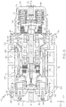
- FIGs. 4 , 5 , and 6 are isometric, cross-sectional, and exploded views, respectively, of an exemplary embodiment of a three parameter isolator 40 suitable for usage as one or all of three parameter isolators 16 shown in FIG. 1 .
- Exemplary three parameter isolator 40 includes a first end portion 44 and a second, opposing end portion 46 .
- End portions 44 and 46 are spaced along the longitudinal or working axis of isolator 40 , which is represented in FIGs. 4-6 by double-headed arrow 48 and corresponds to the X-axis identified in FIG. 5 by coordinate legend 50 .
- End portions 44 and 46 serve as opposing mechanical inputs/outputs of three parameter isolator 40 .
- first end portion 44 can be mounted directly or indirectly to the host spacecraft (e.g., utilizing a mounting bracket 20 , as shown in FIG. 1 ), while second end portion 46 of isolator 40 is attached directly or indirectly to the spacecraft payload (e.g., second end portion 46 may be bolted to or otherwise attached to a bench or palette supporting the spacecraft payload).
- second end portion 46 may be bolted to or otherwise attached to a bench or palette supporting the spacecraft payload.
- the orientation of isolator 16 may be inverted such that second end portion 46 is mounted directly or indirectly to the host spacecraft, while first end portion 44 is secured to the spacecraft payload.
- Three parameter isolator 40 further includes an isolator housing 42 (identified in FIGs. 4 and 5 ), which can be assembled from any number of discrete components or pieces.
- isolator housing 42 includes two end caps 52 and 54 , which are affixed to opposing ends of an axially-elongated, tubular housing piece 56 .
- End cap 52 has a generally flat, disc-like geometry and includes an outer peripheral flange 58 having a number of fastener openings therethrough.
- a number of fasteners e.g., bolts 62 shown in FIGs.
- End cap 52 likewise includes a peripheral flange 64 , which is affixed to the opposing end 66 of tubular housing 56 utilizing a second set of bolts 68 ( FIGs. 4 and 5 ).
- end cap 54 has a tubular or cup-like body, which partially encloses a cylindrical cavity 70 .
- cavity 70 houses an annular grouping of preload springs 72 (a subset of which are labeled in FIGs. 5 and 6 ), an associated spring retainer 74 , and an end portion of a damper assembly 80 further included within isolator 40 , as described in more detail below.
- Three parameter isolator 40 generally includes three active components or devices: (i) a primary or main spring 76 , (ii) a secondary or “tuning" spring 78 , and (iii) a damper assembly 80 .
- main spring 76 may be integrally formed in the annular body of tubular housing piece 56 by machining.
- main spring 76 may assume the form of a section of tubular housing piece 56 from which material has been removed utilizing laser cutting or a similar process to form a compressible resilient structure.
- main spring 76 may be a discrete or independent element, such as a coil spring disposed between opposing end portions 44 and 46 of isolator 40 .
- Secondary spring 78 can also be a coil spring or other discrete, compressible structure, but is also preferably implemented as a machined spring.
- secondary spring 78 can be a machined spring formed in the outer annular wall of a tubular connector piece 82 contained within isolator housing 42 and, specifically, within the central cavity of tubular housing piece 56 .
- a first end of tubular connector piece 82 may be affixed to end cap 52 utilizing, for example, a plurality of bolts 84 (identified in FIG. 5 ) or other such fasteners.
- the second, opposing end of tubular connector piece 82 may be attached to a mating end portion of damper assembly 80 utilizing, for example, an annular bonding or threaded attachment interface.
- damper assembly 80 includes: (i) internally-pressurized bellows 86 and 88 , (ii) a damper assembly sub-housing 90 , and (iii) a piston assembly 92 resiliently coupled to sub-housing 90 through bellows 86 and 88 .
- piston assembly 92 is affixed to tubular connector piece 82 in which tuning spring 78 is formed.
- damper assembly sub-housing 90 is produced to include a peripheral flange 93 , which is fixedly coupled to end cap 46 and second end 66 of tubular housing piece 56 utilizing, for example, a plurality of bolts 94 .
- Piston assembly 92 can thus slide with respect to damper assembly sub-housing 90 along the working axis 48 of isolator 40 .
- Bellows 86 expands and contracts as piston assembly 92 and, more generally, three parameter isolator 40 strokes.
- Bellows 88 by comparison, will expand and contract in relation to the volumetric ratio between bellows 86 and 88 , as well as changes in damping fluid volume due to temperature fluctuations.
- Bellows 86 and 88 are preferably metal bellows, such as edge welded metal bellows; and, in further embodiments of damper assembly 80 , either or both of bellows 86 and 88 may be externally pressurized.
- hydraulic chambers 96 and 98 are provided within sub-housing 90 .
- Hydraulic chambers 96 and 98 are fluidly partitioned, in part, by a piston member 102 of piston assembly 92 . Fluid communication is permitted between hydraulic chambers 96 and 98 , however, through a restricted orifice and, in particular, through an annulus 100 defined by the outer circumferential surface of piston member 102 and the inner circumferential surface of sub-housing 90 .
- Additional hydraulic chambers 104 and 106 are provided within the interior of bellows 86 and 88 , respectively.
- Hydraulic chamber 106 is enclosed by bellows 88 , an end of sub-housing 90 , and a floating bellows cup 108 .
- Preload springs 72 contact the face of bellows cup 108 opposite bellows 88 to exert a preload on cup 108 and pressurize the hydraulic fluid within damper assembly 80 .
- damping fluid e.g., a silicone-based damping fluid
- hydraulic chamber 106 , bellows 88 , and preload springs 72 may collectively serve as a thermal compensation device to help compensate for thermally-inducted fluctuations in damping fluid volume.
- Isolator 40 may initially be distributed without damping fluid, in which case damper assembly 80 may be filled with a selected damping fluid prior to deployment utilizing, for example, a non-illustrated fill port.
- exemplary vibration isolator 40 is a three parameter device, which provides the desirable vibration attenuation characteristics described above; e.g., a relatively low peak transmissibility and superior attenuation of high frequency vibrations.
- K A is the axial stiffness of three parameter isolator 40 , as a whole, which is predominately determined by the axial stiffness of main spring 76 ;
- K B is the volumetric stiffness of isolator 40 , which is predominately determined by the axial stiffness of secondary spring 78 ;
- C A is determined by the damping characteristics of damper assembly 80 .
- vibration isolator 40 need not be a three parameter isolator in all embodiments and, in certain embodiments, may instead assume the form of a single degree of freedom, axially-damping, two parameter isolator including a main spring (e.g., spring 76 ) in parallel with the damper (e.g., damper assembly 80 ), but lacking a secondary spring (e.g., spring 78 ) in parallel with the main spring and in series with the damper.
- main spring e.g., spring 76
- damper e.g., damper assembly 80
- secondary spring e.g., spring 78
- Three parameter isolator 40 is a single-DOF, axial damping device designed to provide vibration attenuation along working axis 48 , which corresponds to the X-axis identified by coordinate legend 50 ( FIG. 5 ).
- the axes orthogonal to working axis 48 are referred to herein as the "lateral" or “radial” axes and corresponding to the Y- and Z-axes further identified by coordinate legend 50 ( FIG. 5 ).
- lateral disturbance forces can induce high-amplitude bending modes in vibration isolators along the lateral axes. As previous described, bending modes can cause significant mechanical stress and possibly damage the components of the isolator absent the provision of adequate countermeasures.
- the lateral modes may be at or near one or more frequencies of particular sensitivity to mission requirements. In such a case, it may be beneficial to effectively shift the lateral bending mode(s) of isolator 40 to higher frequencies less pertinent to or immaterial to mission requirements.
- three parameter isolator 40 is further equipped with a linear guide system 110 , which guides the movement of main spring 76 during operation of isolator 40 .
- linear guide system 40 prevents or at least significantly deters undesired, off-axis movement of main spring 76 ; that is, displacement and rotation of main spring 76 along the lateral axes (the Y- and Z-axes in coordinate legend 50 ) orthogonal to working axis 48 .
- linear guide system 110 may also restrict or prevent rotational of main spring 76 about working axis 48 in certain embodiments; however, this will often be unnecessary as rotation about axis 48 is not problematic in many applications.
- linear guide system 110 may also, as a secondary benefit, likewise help guide the movement of tuning spring 82 and damper assembly 80 by further restricting the motion of these components to axial movement along working axis 48 .
- Linear guide system 110 can assume any form suitable for preventing or at least greatly reducing the lateral or off-axis motion of main spring 76 during operation of isolator 40 .
- linear guide system 110 (identified in FIG. 5 ) will include at least a first guide member 112 and a second guide member 114 , which engage each other in a sliding relationship such that guide system 110 can expand and contract in conjunction with deflection of main spring 76 along working axis 48 .
- guide members 112 and 114 assume the form generally cylindrical bodies, which are coaxial and substantially concentric with one another, with working axis 48 of isolator 40 , and which tubular housing piece 56 /main spring 76 .
- guide member 112 matingly engage in a telescopic relationship.
- guide member 112 is received by an open end of guide member 114 such that member 112 is partially inserted into and circumscribed by member 114 .
- Guide member 112 is fixedly coupled to end 60 of tubular housing piece 56 and, therefore, to a first end of main spring 76 .
- guide member 112 may include an outer peripheral flange 116 , which extends from the tubular body of member 112 and is captured between flange 58 of end cap 52 and end 60 of tubular housing piece 56 when isolator 40 is assembled.
- guide member 114 may include a peripheral flange 118 , which extends from the tubular body of member 114 and is captured between flange 93 of damper assembly 80 and opposing end 66 of tubular housing piece 56 when isolator 40 is assembled.
- guide members 112 and 114 can assume other structural forms and may be fixedly coupled to opposing end portions of isolator 40 and, perhaps, to opposing ends of tubular housing piece 56 /main spring 76 utilizing a different attachment technique or device.
- Guide members 112 and 114 are thus fixedly coupled to the opposing end portions of three parameter isolator 40 between which tubular housing piece 56 and, therefore, main spring 76 extends. Furthermore, as can be seen most readily in FIG. 5 , the tubular body of guide member 112 extends toward the opposing end portion of isolator 40 and, specifically, toward flange 118 of guide member 114, but remains separated therefrom by a first axial gap or annular clearance (called-out by circle 120 in FIG. 5 ).
- the tubular body of guide member 114 likewise extends toward the opposing end portion of isolator 40 and, specifically, toward flange 116 of guide member 112, but is separated therefrom by a second axial gap or annular clearance (called-out by circle 122 in FIG. 5 ).
- These axial gaps or annular clearances enable relative axial movement between guide members 112 and 114 , and therefore the axial expansion and contraction of linear guide system 110 , as main spring 76 deflects along working axis 48 .
- An annular or tubular sliding interface is further formed between guide members 112 and 114 to prevent relative displacement or rotation of members 112 and 114 , and therefore main spring 76 , along the lateral axes orthogonal to working axis 48 .
- the sliding interface formed between guide members 112 and 114 can be provided as a plain bearing or bushing having a generally annular or tubular geometry.
- the inner circumferential surface of guide member 112 may contact the outer circumferential surface of guide member 114 to form a plain annular bearing along which relative sliding motion occurs.
- one or both of the contacting surfaces can be coated with a low friction material (e.g., a polytetrafluoroethylene coating) to reduce stiction.
- a linear bearing system can be provided at the sliding interface between members 112 and 114 .
- a number of annular linear bearing 126 and 128 may be provided, each including a plurality of rolling elements (e.g., rollers or balls) uniformly distributed around the centerline of isolator 40 and linear guide system 110 between members 112 and 114 .
- the spherical rolling elements are retained in slots provided in inner guide member 114 by a number of magnets, which are interspersed with the rolling elements and shown most clearly in FIG.
- linear bearing system 110 By integrating a plurality of linear bearings into linear guide system 110 , multiple low friction points-of-contact between guide members 112 and 114 spaced along the working axis or centerline 48 of isolator 40 are provided. In this manner, the linear bearing system further prevents or deters off-axis rotation of main spring 76 about the lateral axes orthogonal to working axis 48 .
- linear guide system 110 provides a high axial compliance, while also providing high stiffnesses in the lateral directions (again, corresponding to the Y- and Z-axes identified by coordinate legend 50 ).
- linear guide system 110 can be substantially transparent to the normal operation of three parameter isolator 40 , while also minimizing lateral or off-axis motion of main spring 76 to eliminate or reduce higher order bending modes of isolator 40 over the frequency range of interest.
- three parameter isolator 40 can still provide its basic vibration attenuation function absent linear guide system 110 , albeit with an increased propensity toward pronounced lateral modes inducted by random vibrations, lateral impacts, and other lateral disturbance forces.
- linear guide system 110 is not exposed to a damping fluid, the gas of a gas spring (noting that isolator 40 lacks any gas springs), or any other working fluid.
- guide member 112 , guide member 114 , the sliding interface therebetween, and any linear bearings (if provided) are not exposed to a working fluid, these components need not provide any sealing function and may thus be referred to herein as "non-sealing," as may guide system 110 generally.
- non-sealing is therefore expressly defined as describing a structural component or interface that does not contain a pressurized fluid, whether gas or liquid. This term expressly excludes those components exposed to the gas of a gas spring or to the damping fluid of a fluid damper. Accordingly, fluid communication will typically be permitted across the linear sliding interface and any linear bearings (if provided) such that the pressures on opposing sides of these structural components are equivalent.
- guide members 112 and 114 define an inner channel or passage, which fluid communicates with the exterior of isolator 40 and through which secondary spring 78 and damper assembly 80 extend.
- linear guide system 110 greatly reduces lateral bending modes of three parameter isolator 40 in the presence of lateral disturbance forces and/or shifts the lateral modes to higher frequencies less critical or immaterial to mission requirements.
- the envelope or axial length of isolator 40 can be favorably minimized by partially or fully nesting tuning spring 78 and/or series-coupled damper assembly 80 within linear guide system 40 itself. This may be appreciated by again referring to FIGs. 4-6 and specifically FIG. 5 wherein it can be seen that tubular connector piece 82 and tuning spring 78 are partially nested within and circumscribed by guide member 112 of linear guide system 110 .
- damper assembly 80 is nested within and circumscribed by the tubular body of guide member 114 , which is, in turn, circumscribed by the tubular body of guide member 112 . It can also be seen in FIG. 5 that damper assembly 80 extends from one end of guide member 114 , through guide member 114 , and toward the opposing end of guide member 114 for mechanical connection to tubular connector piece 82 and tuning spring 78 . Stated differently, the joinder interface between damper assembly 80 and tuning spring 78 is located within or inboard of linear guide system 110 ; and damper assembly 80 and tuning spring 78 , considered collectively, extend beyond guide system 110 in both axial directions taken along working axis 48 .
- the inner load path of isolator 40 (that is, the K B -C A load path) thus extends through linear guide system 110 between the opposing ends of isolator 40 .
- the outer load path (that is, the K A load path) further extends around and circumscribes linear guide system 110 in the illustrated example.
- linear guide system 110 can be disposed outboard of main spring 76 such that the outer load path (the K A load path) further extends through system 110 .
- main spring 76 is preferably disposed radially adjacent linear guide system 110 .
- a three parameter isolator including a main spring linear guide system has thus been provided.
- the linear guide system prevents or at least significantly deters both lateral displacement and rotation of the main spring along axes orthogonal to the working axis of the isolator.
- the guide system can greatly reduce lateral modes through the isolator and/or shift the lateral to higher frequencies less critical or immaterial to mission requirements.
- the envelope or axial length of the isolator can be minimized by nesting the tuning spring and/or the series-coupled damper assembly within the guide system itself.
- the main spring linear guide system may span the length of the flexible portion of the isolator and the main spring, which can be positioned either radially inboard or outboard of the guide system. Additionally, in preferred embodiments, the linear guide system is non-sealing and fluidly isolated from the damper assembly; that is, no portion of the guide system is exposed to or touches the damping fluid contained within the damper assembly.
- the linear guide system included two mating guide members in the form of two telescoping tubes or a sleeve-shaft configuration.
- the telescoping tubes are fixedly coupled to opposing ends of the main spring and, thus, slide relative to one another as the main spring and, more generally, the isolator deflects (compresses and expands) along the working axis.
- the linear guide system can be implemented in other manners, as well.
- the linear guide system it is possible for the linear guide system to include a single guide member that forms a sliding interface with the main spring itself to restrict undesired off-axis motion of the main spring.
- the guide member can be disposed either radially inboard or outboard of the main spring, and various bearings or bearing systems can be integrated into either the main spring or the guide member.
- the main spring linear guide system can include still other types of guide members, which can vary in number and structural configuration. For example, a plurality of pins circumferentially spaced about the working axis can be affixed to one end of the main spring or isolator; while a plurality of tubes, sleeves, or slotted members are affixed to the opposing end of the main spring or isolator.
- the pins may be received by and slide relative to the tubes, sleeves, or slotted members as the main spring deflects along the working axis to prevent displacement and rotation of the main spring along first and second axes orthogonal to the working axis. Such an arrangement also deters rotation of the main spring about the working axis itself, which may be a desirable characteristic in certain applications.
Claims (9)
- Isolateur (16) ayant un axe de travail (48), l'isolateur comprenant :une première partie d'extrémité (44) ;une seconde partie d'extrémité (46) espacée de la première partie d'extrémité le long de l'axe de travail ;un ressort principal (76) couplé mécaniquement entre les première et seconde parties d'extrémité ; etun système de guidage linéaire (110) s'étendant depuis la première partie d'extrémité, à travers le ressort principal, et vers la seconde partie d'extrémité, le système de guidage linéaire s'étendant et se rétractant en association avec la flexion du ressort principal le long de l'axe de travail, tout en limitant le déplacement et la rotation du ressort principal le long des premier et second axes orthogonaux à l'axe de travail ;caractérisé en ce que l'isolateur comprend en outre :un ensemble amortisseur (80) contenant un fluide accouplé mécaniquement entre les première et seconde parties d'extrémité en parallèle avec le ressort principal ; etun ressort de réglage (78) accouplé mécaniquement entre les première et seconde parties d'extrémité en parallèle avec le ressort principal et en série avec l'ensemble amortisseur contenant un fluide ; etcaractérisé en outre en ce que l'ensemble amortisseur contenant un fluide et le ressort de réglage sont imbriqués, au moins en grande partie, dans le système de guidage linéaire.
- Isolateur (16) selon la revendication 1, l'ensemble amortisseur (80) contenant un fluide retenant un volume de fluide amortisseur pendant le fonctionnement de l'isolateur (16), et le système de guidage linéaire (110) étant isolé de façon fluidique du fluide amortisseur.
- Isolateur (16) selon la revendication 1, le ressort principal (76) délimitant au moins une majorité du système de guidage linéaire (110).
- Isolateur (16) selon la revendication 1, le système de guidage linéaire (110) comprenant :un premier corps tubulaire (112) accouplé de manière fixe à la première partie d'extrémité (44) de l'isolateur et s'étendant vers la seconde partie (46) de l'isolateur, mais séparé de celle-ci par un premier espace axial (120) ; etun second corps tubulaire (114) fixé à la seconde partie d'extrémité de l'isolateur et s'étendant vers la première partie d'extrémité de l'isolateur, mais séparé de celle-ci par un second espace axial (122).
- Isolateur (16) selon la revendication 4, une partie du premier corps tubulaire (112) étant reçue télescopiquement à l'intérieur du second corps tubulaire (114), et une interface coulissante annulaire étant formée entre les premier et second corps tubulaires.
- Isolateur (16) selon la revendication 5 comprenant en outre :un premier palier linéaire annulaire (126) disposé entre les premier et second corps tubulaires (112, 114) et s'étendant autour de l'interface coulissante annulaire ; etun second palier linéaire annulaire (128) disposé entre les premier et second corps tubulaires et s'étendant autour de l'interface coulissante annulaire, les premier et second paliers linéaires annulaires étant espacés longitudinalement le long de l'axe de travail (48).
- Isolateur (16) selon la revendication 1 comprenant en outre :un trajet de charge externe s'étendant de la première partie d'extrémité (44), à travers le ressort principal (76), et vers la seconde partie d'extrémité (46) ; etun trajet de charge interne parallèle au trajet de charge externe et contournant le ressort principal, le trajet de charge interne s'étendant de la première partie d'extrémité, à travers le système de guidage linéaire (110), et vers la seconde partie d'extrémité.
- Isolateur (16) selon la revendication 1, le système de guidage linéaire (110) n'étant pas étanche.
- Isolateur (16) selon la revendication 1, le système de guidage linéaire (110) comprenant :un premier élément de guidage (112) accouplé de manière fixe à une première extrémité du ressort principal ;un second élément de guidage (114) accouplé de manière fixe à une seconde extrémité du ressort principal opposée à la première extrémité du ressort principal ;un premier palier linéaire annulaire (126) disposé entre les premier et second éléments de guidage et comprenant une première pluralité d'éléments roulants ; etun second palier linéaire annulaire (128) disposé en outre entre les premier et second éléments de guidage, comprenant une seconde pluralité d'éléments roulants, et espacé du premier palier linéaire annulaire le long de l'axe de travail (48).
Applications Claiming Priority (1)
| Application Number | Priority Date | Filing Date | Title |
|---|---|---|---|
| US14/807,551 US9618077B2 (en) | 2015-07-23 | 2015-07-23 | Isolators including main spring linear guide systems |
Publications (3)
| Publication Number | Publication Date |
|---|---|
| EP3121480A2 EP3121480A2 (fr) | 2017-01-25 |
| EP3121480A3 EP3121480A3 (fr) | 2017-03-22 |
| EP3121480B1 true EP3121480B1 (fr) | 2019-03-06 |
Family
ID=56097989
Family Applications (1)
| Application Number | Title | Priority Date | Filing Date |
|---|---|---|---|
| EP16168522.7A Active EP3121480B1 (fr) | 2015-07-23 | 2016-05-05 | Isolateurs comprenant des systèmes de guidage linéaire pour ressort principal |
Country Status (3)
| Country | Link |
|---|---|
| US (1) | US9618077B2 (fr) |
| EP (1) | EP3121480B1 (fr) |
| JP (1) | JP2017026142A (fr) |
Families Citing this family (2)
| Publication number | Priority date | Publication date | Assignee | Title |
|---|---|---|---|---|
| US10066697B2 (en) | 2017-01-23 | 2018-09-04 | Honeywell International Inc. | Three parameter isolators containing rolling seal damper assemblies |
| US10451139B2 (en) * | 2017-11-30 | 2019-10-22 | Honeywell International Inc. | Damping coefficient-regulating inductive heating systems and isolator assemblies including the same |
Family Cites Families (35)
| Publication number | Priority date | Publication date | Assignee | Title |
|---|---|---|---|---|
| FR1044393A (fr) | 1951-05-07 | 1953-11-17 | Dispositif de suspension pour voitures automobiles munies d'amortisse ? du type télescopique | |
| DE1682518U (de) | 1954-05-15 | 1954-09-02 | Hemscheidt Maschf Hermann | Federbein. |
| DE1023345B (de) | 1956-05-11 | 1958-01-23 | Daimler Benz Ag | Sicherung gegen das Abheben von Schraubenfedern von ihrer Auflage, insbesondere fuer Fahrzeugfederungen |
| DE1209444B (de) | 1960-07-09 | 1966-01-20 | Boge Gmbh | Federbein mit zuschaltbarer Tragfeder, insbesondere fuer Kraftfahrzeuge |
| GB1240894A (en) | 1968-09-16 | 1971-07-28 | Norman Dennis Allen Hall | Isolators for vibration, noise and shock control |
| US3559976A (en) | 1968-10-17 | 1971-02-02 | Joseph Jerz Jr | Variable stiffness suspension system |
| US3743059A (en) | 1971-11-15 | 1973-07-03 | Trw Inc | Mechanical isolator and damper |
| US4736983A (en) | 1986-11-26 | 1988-04-12 | Furbee Raymond D | Shock absorber for a bicycle seat |
| FR2610055B1 (fr) | 1987-01-23 | 1991-07-19 | Caoutchouc Manuf Plastique | Dispositif d'isolation antivibratoire a amortissement hydraulique de l'elasticite radiale et procedes de realisation d'un tel dispositif |
| JP2793588B2 (ja) | 1988-01-12 | 1998-09-03 | 日産自動車株式会社 | 液体入りブツシユ形防振装置 |
| US5044648A (en) * | 1989-04-18 | 1991-09-03 | Knapp Thomas D | Bicycle suspension system |
| JPH03181635A (ja) | 1989-12-11 | 1991-08-07 | Toyoda Gosei Co Ltd | 液封入防振装置 |
| JP2583145B2 (ja) | 1990-05-22 | 1997-02-19 | 丸五ゴム工業株式会社 | 流体封入型防振装置 |
| US5397113A (en) | 1991-02-22 | 1995-03-14 | Bridgestone Corporation | Vibration isolation apparatus |
| JP3181635B2 (ja) | 1991-08-28 | 2001-07-03 | 化成オプトニクス株式会社 | 蛍光体用青色顔料の製造方法及び顔料付青色発光蛍光体 |
| US5332060A (en) | 1993-03-10 | 1994-07-26 | New Venture Gear, Inc. | Linear actuation mechanism for electronically-controlled torque modulated transfer case |
| US5332070A (en) * | 1993-04-21 | 1994-07-26 | Honeywell Inc. | Three parameter viscous damper and isolator |
| US5501434A (en) | 1994-05-10 | 1996-03-26 | Lord Corporation | Hybrid fluid and elastomer damper |
| DE4420134C1 (de) | 1994-06-09 | 1995-10-05 | Fichtel & Sachs Ag | Schwingungsdämpfer mit mechanischem Zuganschlag |
| US5788372A (en) | 1996-05-10 | 1998-08-04 | Lord Corporation | Method and apparatus for reducing transient motion between an aircraft power member and structure during takeoff, landing and maneuvers |
| US5803213A (en) * | 1997-02-03 | 1998-09-08 | Honeywell Inc. | Heavy load vibration isolation apparatus |
| ES2146518B1 (es) * | 1997-07-15 | 2001-02-16 | Muller Carranza Luis | Mejoras introducidas en las guias para columnas de muelles de discos conicos superpuestos. |
| US6135434A (en) | 1998-02-03 | 2000-10-24 | Fox Factory, Inc. | Shock absorber with positive and negative gas spring chambers |
| US6082719A (en) | 1998-05-12 | 2000-07-04 | Trw Inc. | Spacecraft antenna vibration control damper |
| US6959795B2 (en) | 2002-02-20 | 2005-11-01 | Csa Engineering, Inc. | Hybrid pneumatic-magnetic isolator-actuator |
| GB2404716B (en) | 2003-08-08 | 2007-07-25 | Ultra Electronics Ltd | A vibration isolation mount and method |
| JP4120828B2 (ja) | 2004-06-30 | 2008-07-16 | 東海ゴム工業株式会社 | 流体封入式能動型防振装置 |
| US7172178B1 (en) | 2004-11-24 | 2007-02-06 | Walbro Engine Management, L.L.C. | Carburetor with acceleration fuel pump |
| DE102005001744B3 (de) | 2005-01-14 | 2006-07-06 | Zf Friedrichshafen Ag | Federträger mit verstellbarem Federteller |
| US7182188B2 (en) * | 2005-02-16 | 2007-02-27 | Honeywell International, Inc. | Isolator using externally pressurized sealing bellows |
| JP4382822B2 (ja) | 2007-01-11 | 2009-12-16 | 本田技研工業株式会社 | 筒形防振装置 |
| US8327985B2 (en) * | 2009-06-22 | 2012-12-11 | Honeywell International Inc. | Two stage vibration isolator |
| US9046001B2 (en) | 2011-08-29 | 2015-06-02 | Honeywell International Inc. | Annular bearing support dampers, gas turbine engines including the same, and methods for the manufacture thereof |
| CN105378324B (zh) | 2013-07-12 | 2018-03-16 | 株式会社昭和 | 液压式减震器和盖构件 |
| US9458907B2 (en) * | 2014-10-02 | 2016-10-04 | Honeywell International Inc. | Vibration isolation systems including multi-parameter isolators providing piezoelectric-based damping |
-
2015
- 2015-07-23 US US14/807,551 patent/US9618077B2/en active Active
-
2016
- 2016-05-05 EP EP16168522.7A patent/EP3121480B1/fr active Active
- 2016-05-11 JP JP2016095338A patent/JP2017026142A/ja active Pending
Non-Patent Citations (1)
| Title |
|---|
| None * |
Also Published As
| Publication number | Publication date |
|---|---|
| EP3121480A3 (fr) | 2017-03-22 |
| EP3121480A2 (fr) | 2017-01-25 |
| US9618077B2 (en) | 2017-04-11 |
| JP2017026142A (ja) | 2017-02-02 |
| US20170023092A1 (en) | 2017-01-26 |
Similar Documents
| Publication | Publication Date | Title |
|---|---|---|
| EP2518366B1 (fr) | Isolateurs multi-axes à trois paramètres | |
| EP1848899B1 (fr) | Isolateur ameliore utilisant des soufflets d'etancheite pressurises exterieurement | |
| US9416842B2 (en) | Isolators having damper-external thermal compensators and spacecraft isolation systems employing the same | |
| US9453552B2 (en) | Adaptive three parameter isolator assemblies including external magneto-rheological valves | |
| EP2940345B1 (fr) | Isolateurs avec trois paramètres de profil bas et systèmes d'isolation employant ceux-ci | |
| EP2607240A2 (fr) | Dispositifs d'isolation passive pour amortissement de fréquence basse de charges utiles de faible masse et systèmes d'isolation d'engin spatial employant celui-ci | |
| US8444121B2 (en) | Systems for damping vibrations from a payload | |
| US9458907B2 (en) | Vibration isolation systems including multi-parameter isolators providing piezoelectric-based damping | |
| EP2921741A2 (fr) | Isolateur de vibrations utilisant un soufflet d'étanchéité sous pression depuis l'extérieur et un arbre externe | |
| EP3121480B1 (fr) | Isolateurs comprenant des systèmes de guidage linéaire pour ressort principal | |
| US9670983B2 (en) | Isolators including damper assemblies having variable annuli and spacecraft isolation systems employing the same | |
| EP3354930B1 (fr) | Isolateurs à trois paramètres contenant des ensembles amortisseurs comprenant une membrane déroulante | |
| JP2008539385A (ja) | 減衰又は隔離システムのための磁気軸受 | |
| JP2015102244A (ja) | 入れ子式フレキシャデバイスを有するアイソレータおよびその製造のための方法 | |
| EP2251263B1 (fr) | Ensemble de rotor doté d'un élément amortisseur intégré pour le déploiement dans un dispositif de contrôle de la quantité de mouvement | |
| EP0339113B1 (fr) | Amortisseur de vibrations et dispositif d'isolation |
Legal Events
| Date | Code | Title | Description |
|---|---|---|---|
| PUAI | Public reference made under article 153(3) epc to a published international application that has entered the european phase |
Free format text: ORIGINAL CODE: 0009012 |
|
| STAA | Information on the status of an ep patent application or granted ep patent |
Free format text: STATUS: REQUEST FOR EXAMINATION WAS MADE |
|
| 17P | Request for examination filed |
Effective date: 20160505 |
|
| AK | Designated contracting states |
Kind code of ref document: A2 Designated state(s): AL AT BE BG CH CY CZ DE DK EE ES FI FR GB GR HR HU IE IS IT LI LT LU LV MC MK MT NL NO PL PT RO RS SE SI SK SM TR |
|
| AX | Request for extension of the european patent |
Extension state: BA ME |
|
| PUAL | Search report despatched |
Free format text: ORIGINAL CODE: 0009013 |
|
| AK | Designated contracting states |
Kind code of ref document: A3 Designated state(s): AL AT BE BG CH CY CZ DE DK EE ES FI FR GB GR HR HU IE IS IT LI LT LU LV MC MK MT NL NO PL PT RO RS SE SI SK SM TR |
|
| AX | Request for extension of the european patent |
Extension state: BA ME |
|
| RIC1 | Information provided on ipc code assigned before grant |
Ipc: F16F 1/02 20060101ALI20170213BHEP Ipc: F16F 15/02 20060101AFI20170213BHEP Ipc: F16F 13/00 20060101ALI20170213BHEP Ipc: F16F 1/12 20060101ALI20170213BHEP |
|
| GRAP | Despatch of communication of intention to grant a patent |
Free format text: ORIGINAL CODE: EPIDOSNIGR1 |
|
| STAA | Information on the status of an ep patent application or granted ep patent |
Free format text: STATUS: GRANT OF PATENT IS INTENDED |
|
| INTG | Intention to grant announced |
Effective date: 20181011 |
|
| GRAS | Grant fee paid |
Free format text: ORIGINAL CODE: EPIDOSNIGR3 |
|
| GRAA | (expected) grant |
Free format text: ORIGINAL CODE: 0009210 |
|
| STAA | Information on the status of an ep patent application or granted ep patent |
Free format text: STATUS: THE PATENT HAS BEEN GRANTED |
|
| AK | Designated contracting states |
Kind code of ref document: B1 Designated state(s): AL AT BE BG CH CY CZ DE DK EE ES FI FR GB GR HR HU IE IS IT LI LT LU LV MC MK MT NL NO PL PT RO RS SE SI SK SM TR |
|
| REG | Reference to a national code |
Ref country code: GB Ref legal event code: FG4D |
|
| REG | Reference to a national code |
Ref country code: CH Ref legal event code: EP Ref country code: AT Ref legal event code: REF Ref document number: 1104972 Country of ref document: AT Kind code of ref document: T Effective date: 20190315 |
|
| REG | Reference to a national code |
Ref country code: DE Ref legal event code: R096 Ref document number: 602016010571 Country of ref document: DE |
|
| REG | Reference to a national code |
Ref country code: IE Ref legal event code: FG4D |
|
| REG | Reference to a national code |
Ref country code: NL Ref legal event code: MP Effective date: 20190306 |
|
| REG | Reference to a national code |
Ref country code: LT Ref legal event code: MG4D |
|
| PG25 | Lapsed in a contracting state [announced via postgrant information from national office to epo] |
Ref country code: NO Free format text: LAPSE BECAUSE OF FAILURE TO SUBMIT A TRANSLATION OF THE DESCRIPTION OR TO PAY THE FEE WITHIN THE PRESCRIBED TIME-LIMIT Effective date: 20190606 Ref country code: LT Free format text: LAPSE BECAUSE OF FAILURE TO SUBMIT A TRANSLATION OF THE DESCRIPTION OR TO PAY THE FEE WITHIN THE PRESCRIBED TIME-LIMIT Effective date: 20190306 Ref country code: SE Free format text: LAPSE BECAUSE OF FAILURE TO SUBMIT A TRANSLATION OF THE DESCRIPTION OR TO PAY THE FEE WITHIN THE PRESCRIBED TIME-LIMIT Effective date: 20190306 Ref country code: FI Free format text: LAPSE BECAUSE OF FAILURE TO SUBMIT A TRANSLATION OF THE DESCRIPTION OR TO PAY THE FEE WITHIN THE PRESCRIBED TIME-LIMIT Effective date: 20190306 |
|
| PG25 | Lapsed in a contracting state [announced via postgrant information from national office to epo] |
Ref country code: RS Free format text: LAPSE BECAUSE OF FAILURE TO SUBMIT A TRANSLATION OF THE DESCRIPTION OR TO PAY THE FEE WITHIN THE PRESCRIBED TIME-LIMIT Effective date: 20190306 Ref country code: NL Free format text: LAPSE BECAUSE OF FAILURE TO SUBMIT A TRANSLATION OF THE DESCRIPTION OR TO PAY THE FEE WITHIN THE PRESCRIBED TIME-LIMIT Effective date: 20190306 Ref country code: BG Free format text: LAPSE BECAUSE OF FAILURE TO SUBMIT A TRANSLATION OF THE DESCRIPTION OR TO PAY THE FEE WITHIN THE PRESCRIBED TIME-LIMIT Effective date: 20190606 Ref country code: LV Free format text: LAPSE BECAUSE OF FAILURE TO SUBMIT A TRANSLATION OF THE DESCRIPTION OR TO PAY THE FEE WITHIN THE PRESCRIBED TIME-LIMIT Effective date: 20190306 Ref country code: GR Free format text: LAPSE BECAUSE OF FAILURE TO SUBMIT A TRANSLATION OF THE DESCRIPTION OR TO PAY THE FEE WITHIN THE PRESCRIBED TIME-LIMIT Effective date: 20190607 Ref country code: HR Free format text: LAPSE BECAUSE OF FAILURE TO SUBMIT A TRANSLATION OF THE DESCRIPTION OR TO PAY THE FEE WITHIN THE PRESCRIBED TIME-LIMIT Effective date: 20190306 |
|
| REG | Reference to a national code |
Ref country code: AT Ref legal event code: MK05 Ref document number: 1104972 Country of ref document: AT Kind code of ref document: T Effective date: 20190306 |
|
| PG25 | Lapsed in a contracting state [announced via postgrant information from national office to epo] |
Ref country code: EE Free format text: LAPSE BECAUSE OF FAILURE TO SUBMIT A TRANSLATION OF THE DESCRIPTION OR TO PAY THE FEE WITHIN THE PRESCRIBED TIME-LIMIT Effective date: 20190306 Ref country code: IT Free format text: LAPSE BECAUSE OF FAILURE TO SUBMIT A TRANSLATION OF THE DESCRIPTION OR TO PAY THE FEE WITHIN THE PRESCRIBED TIME-LIMIT Effective date: 20190306 Ref country code: SK Free format text: LAPSE BECAUSE OF FAILURE TO SUBMIT A TRANSLATION OF THE DESCRIPTION OR TO PAY THE FEE WITHIN THE PRESCRIBED TIME-LIMIT Effective date: 20190306 Ref country code: AL Free format text: LAPSE BECAUSE OF FAILURE TO SUBMIT A TRANSLATION OF THE DESCRIPTION OR TO PAY THE FEE WITHIN THE PRESCRIBED TIME-LIMIT Effective date: 20190306 Ref country code: PT Free format text: LAPSE BECAUSE OF FAILURE TO SUBMIT A TRANSLATION OF THE DESCRIPTION OR TO PAY THE FEE WITHIN THE PRESCRIBED TIME-LIMIT Effective date: 20190706 Ref country code: ES Free format text: LAPSE BECAUSE OF FAILURE TO SUBMIT A TRANSLATION OF THE DESCRIPTION OR TO PAY THE FEE WITHIN THE PRESCRIBED TIME-LIMIT Effective date: 20190306 Ref country code: CZ Free format text: LAPSE BECAUSE OF FAILURE TO SUBMIT A TRANSLATION OF THE DESCRIPTION OR TO PAY THE FEE WITHIN THE PRESCRIBED TIME-LIMIT Effective date: 20190306 Ref country code: RO Free format text: LAPSE BECAUSE OF FAILURE TO SUBMIT A TRANSLATION OF THE DESCRIPTION OR TO PAY THE FEE WITHIN THE PRESCRIBED TIME-LIMIT Effective date: 20190306 |
|
| PG25 | Lapsed in a contracting state [announced via postgrant information from national office to epo] |
Ref country code: SM Free format text: LAPSE BECAUSE OF FAILURE TO SUBMIT A TRANSLATION OF THE DESCRIPTION OR TO PAY THE FEE WITHIN THE PRESCRIBED TIME-LIMIT Effective date: 20190306 Ref country code: PL Free format text: LAPSE BECAUSE OF FAILURE TO SUBMIT A TRANSLATION OF THE DESCRIPTION OR TO PAY THE FEE WITHIN THE PRESCRIBED TIME-LIMIT Effective date: 20190306 |
|
| REG | Reference to a national code |
Ref country code: DE Ref legal event code: R097 Ref document number: 602016010571 Country of ref document: DE |
|
| REG | Reference to a national code |
Ref country code: CH Ref legal event code: PL |
|
| PG25 | Lapsed in a contracting state [announced via postgrant information from national office to epo] |
Ref country code: AT Free format text: LAPSE BECAUSE OF FAILURE TO SUBMIT A TRANSLATION OF THE DESCRIPTION OR TO PAY THE FEE WITHIN THE PRESCRIBED TIME-LIMIT Effective date: 20190306 Ref country code: IS Free format text: LAPSE BECAUSE OF FAILURE TO SUBMIT A TRANSLATION OF THE DESCRIPTION OR TO PAY THE FEE WITHIN THE PRESCRIBED TIME-LIMIT Effective date: 20190706 |
|
| PLBE | No opposition filed within time limit |
Free format text: ORIGINAL CODE: 0009261 |
|
| STAA | Information on the status of an ep patent application or granted ep patent |
Free format text: STATUS: NO OPPOSITION FILED WITHIN TIME LIMIT |
|
| PG25 | Lapsed in a contracting state [announced via postgrant information from national office to epo] |
Ref country code: DK Free format text: LAPSE BECAUSE OF FAILURE TO SUBMIT A TRANSLATION OF THE DESCRIPTION OR TO PAY THE FEE WITHIN THE PRESCRIBED TIME-LIMIT Effective date: 20190306 Ref country code: LI Free format text: LAPSE BECAUSE OF NON-PAYMENT OF DUE FEES Effective date: 20190531 Ref country code: CH Free format text: LAPSE BECAUSE OF NON-PAYMENT OF DUE FEES Effective date: 20190531 Ref country code: MC Free format text: LAPSE BECAUSE OF FAILURE TO SUBMIT A TRANSLATION OF THE DESCRIPTION OR TO PAY THE FEE WITHIN THE PRESCRIBED TIME-LIMIT Effective date: 20190306 |
|
| REG | Reference to a national code |
Ref country code: BE Ref legal event code: MM Effective date: 20190531 |
|
| 26N | No opposition filed |
Effective date: 20191209 |
|
| PG25 | Lapsed in a contracting state [announced via postgrant information from national office to epo] |
Ref country code: SI Free format text: LAPSE BECAUSE OF FAILURE TO SUBMIT A TRANSLATION OF THE DESCRIPTION OR TO PAY THE FEE WITHIN THE PRESCRIBED TIME-LIMIT Effective date: 20190306 Ref country code: LU Free format text: LAPSE BECAUSE OF NON-PAYMENT OF DUE FEES Effective date: 20190505 |
|
| PG25 | Lapsed in a contracting state [announced via postgrant information from national office to epo] |
Ref country code: TR Free format text: LAPSE BECAUSE OF FAILURE TO SUBMIT A TRANSLATION OF THE DESCRIPTION OR TO PAY THE FEE WITHIN THE PRESCRIBED TIME-LIMIT Effective date: 20190306 |
|
| PG25 | Lapsed in a contracting state [announced via postgrant information from national office to epo] |
Ref country code: IE Free format text: LAPSE BECAUSE OF NON-PAYMENT OF DUE FEES Effective date: 20190505 |
|
| PG25 | Lapsed in a contracting state [announced via postgrant information from national office to epo] |
Ref country code: BE Free format text: LAPSE BECAUSE OF NON-PAYMENT OF DUE FEES Effective date: 20190531 |
|
| GBPC | Gb: european patent ceased through non-payment of renewal fee |
Effective date: 20200505 |
|
| PG25 | Lapsed in a contracting state [announced via postgrant information from national office to epo] |
Ref country code: GB Free format text: LAPSE BECAUSE OF NON-PAYMENT OF DUE FEES Effective date: 20200505 |
|
| PG25 | Lapsed in a contracting state [announced via postgrant information from national office to epo] |
Ref country code: CY Free format text: LAPSE BECAUSE OF FAILURE TO SUBMIT A TRANSLATION OF THE DESCRIPTION OR TO PAY THE FEE WITHIN THE PRESCRIBED TIME-LIMIT Effective date: 20190306 |
|
| PG25 | Lapsed in a contracting state [announced via postgrant information from national office to epo] |
Ref country code: HU Free format text: LAPSE BECAUSE OF FAILURE TO SUBMIT A TRANSLATION OF THE DESCRIPTION OR TO PAY THE FEE WITHIN THE PRESCRIBED TIME-LIMIT; INVALID AB INITIO Effective date: 20160505 Ref country code: MT Free format text: LAPSE BECAUSE OF FAILURE TO SUBMIT A TRANSLATION OF THE DESCRIPTION OR TO PAY THE FEE WITHIN THE PRESCRIBED TIME-LIMIT Effective date: 20190306 |
|
| PG25 | Lapsed in a contracting state [announced via postgrant information from national office to epo] |
Ref country code: MK Free format text: LAPSE BECAUSE OF FAILURE TO SUBMIT A TRANSLATION OF THE DESCRIPTION OR TO PAY THE FEE WITHIN THE PRESCRIBED TIME-LIMIT Effective date: 20190306 |
|
| P01 | Opt-out of the competence of the unified patent court (upc) registered |
Effective date: 20230525 |
|
| PGFP | Annual fee paid to national office [announced via postgrant information from national office to epo] |
Ref country code: FR Payment date: 20230523 Year of fee payment: 8 Ref country code: DE Payment date: 20230530 Year of fee payment: 8 |