EP3117942A1 - Lames d'outil et leurs fabrication - Google Patents
Lames d'outil et leurs fabrication Download PDFInfo
- Publication number
- EP3117942A1 EP3117942A1 EP16175555.8A EP16175555A EP3117942A1 EP 3117942 A1 EP3117942 A1 EP 3117942A1 EP 16175555 A EP16175555 A EP 16175555A EP 3117942 A1 EP3117942 A1 EP 3117942A1
- Authority
- EP
- European Patent Office
- Prior art keywords
- radiation
- binder layer
- abrasive particles
- backing strip
- binding
- Prior art date
- Legal status (The legal status is an assumption and is not a legal conclusion. Google has not performed a legal analysis and makes no representation as to the accuracy of the status listed.)
- Granted
Links
Images


Classifications
-
- B—PERFORMING OPERATIONS; TRANSPORTING
- B23—MACHINE TOOLS; METAL-WORKING NOT OTHERWISE PROVIDED FOR
- B23P—METAL-WORKING NOT OTHERWISE PROVIDED FOR; COMBINED OPERATIONS; UNIVERSAL MACHINE TOOLS
- B23P15/00—Making specific metal objects by operations not covered by a single other subclass or a group in this subclass
- B23P15/28—Making specific metal objects by operations not covered by a single other subclass or a group in this subclass cutting tools
-
- B—PERFORMING OPERATIONS; TRANSPORTING
- B23—MACHINE TOOLS; METAL-WORKING NOT OTHERWISE PROVIDED FOR
- B23D—PLANING; SLOTTING; SHEARING; BROACHING; SAWING; FILING; SCRAPING; LIKE OPERATIONS FOR WORKING METAL BY REMOVING MATERIAL, NOT OTHERWISE PROVIDED FOR
- B23D61/00—Tools for sawing machines or sawing devices; Clamping devices for these tools
- B23D61/12—Straight saw blades; Strap saw blades
-
- B—PERFORMING OPERATIONS; TRANSPORTING
- B23—MACHINE TOOLS; METAL-WORKING NOT OTHERWISE PROVIDED FOR
- B23D—PLANING; SLOTTING; SHEARING; BROACHING; SAWING; FILING; SCRAPING; LIKE OPERATIONS FOR WORKING METAL BY REMOVING MATERIAL, NOT OTHERWISE PROVIDED FOR
- B23D61/00—Tools for sawing machines or sawing devices; Clamping devices for these tools
- B23D61/18—Sawing tools of special type, e.g. wire saw strands, saw blades or saw wire equipped with diamonds or other abrasive particles in selected individual positions
-
- B—PERFORMING OPERATIONS; TRANSPORTING
- B23—MACHINE TOOLS; METAL-WORKING NOT OTHERWISE PROVIDED FOR
- B23D—PLANING; SLOTTING; SHEARING; BROACHING; SAWING; FILING; SCRAPING; LIKE OPERATIONS FOR WORKING METAL BY REMOVING MATERIAL, NOT OTHERWISE PROVIDED FOR
- B23D63/00—Dressing the tools of sawing machines or sawing devices for use in cutting any kind of material, e.g. in the manufacture of sawing tools
-
- B—PERFORMING OPERATIONS; TRANSPORTING
- B23—MACHINE TOOLS; METAL-WORKING NOT OTHERWISE PROVIDED FOR
- B23D—PLANING; SLOTTING; SHEARING; BROACHING; SAWING; FILING; SCRAPING; LIKE OPERATIONS FOR WORKING METAL BY REMOVING MATERIAL, NOT OTHERWISE PROVIDED FOR
- B23D65/00—Making tools for sawing machines or sawing devices for use in cutting any kind of material
-
- B—PERFORMING OPERATIONS; TRANSPORTING
- B23—MACHINE TOOLS; METAL-WORKING NOT OTHERWISE PROVIDED FOR
- B23K—SOLDERING OR UNSOLDERING; WELDING; CLADDING OR PLATING BY SOLDERING OR WELDING; CUTTING BY APPLYING HEAT LOCALLY, e.g. FLAME CUTTING; WORKING BY LASER BEAM
- B23K1/00—Soldering, e.g. brazing, or unsoldering
- B23K1/005—Soldering by means of radiant energy
- B23K1/0056—Soldering by means of radiant energy soldering by means of beams, e.g. lasers, E.B.
-
- B—PERFORMING OPERATIONS; TRANSPORTING
- B23—MACHINE TOOLS; METAL-WORKING NOT OTHERWISE PROVIDED FOR
- B23K—SOLDERING OR UNSOLDERING; WELDING; CLADDING OR PLATING BY SOLDERING OR WELDING; CUTTING BY APPLYING HEAT LOCALLY, e.g. FLAME CUTTING; WORKING BY LASER BEAM
- B23K1/00—Soldering, e.g. brazing, or unsoldering
- B23K1/20—Preliminary treatment of work or areas to be soldered, e.g. in respect of a galvanic coating
-
- B—PERFORMING OPERATIONS; TRANSPORTING
- B23—MACHINE TOOLS; METAL-WORKING NOT OTHERWISE PROVIDED FOR
- B23K—SOLDERING OR UNSOLDERING; WELDING; CLADDING OR PLATING BY SOLDERING OR WELDING; CUTTING BY APPLYING HEAT LOCALLY, e.g. FLAME CUTTING; WORKING BY LASER BEAM
- B23K15/00—Electron-beam welding or cutting
- B23K15/0046—Welding
- B23K15/0086—Welding welding for purposes other than joining, e.g. built-up welding
-
- B—PERFORMING OPERATIONS; TRANSPORTING
- B23—MACHINE TOOLS; METAL-WORKING NOT OTHERWISE PROVIDED FOR
- B23K—SOLDERING OR UNSOLDERING; WELDING; CLADDING OR PLATING BY SOLDERING OR WELDING; CUTTING BY APPLYING HEAT LOCALLY, e.g. FLAME CUTTING; WORKING BY LASER BEAM
- B23K26/00—Working by laser beam, e.g. welding, cutting or boring
- B23K26/34—Laser welding for purposes other than joining
-
- B—PERFORMING OPERATIONS; TRANSPORTING
- B23—MACHINE TOOLS; METAL-WORKING NOT OTHERWISE PROVIDED FOR
- B23K—SOLDERING OR UNSOLDERING; WELDING; CLADDING OR PLATING BY SOLDERING OR WELDING; CUTTING BY APPLYING HEAT LOCALLY, e.g. FLAME CUTTING; WORKING BY LASER BEAM
- B23K31/00—Processes relevant to this subclass, specially adapted for particular articles or purposes, but not covered by only one of the preceding main groups
- B23K31/02—Processes relevant to this subclass, specially adapted for particular articles or purposes, but not covered by only one of the preceding main groups relating to soldering or welding
- B23K31/025—Connecting cutting edges or the like to tools; Attaching reinforcements to workpieces, e.g. wear-resisting zones to tableware
-
- B—PERFORMING OPERATIONS; TRANSPORTING
- B23—MACHINE TOOLS; METAL-WORKING NOT OTHERWISE PROVIDED FOR
- B23K—SOLDERING OR UNSOLDERING; WELDING; CLADDING OR PLATING BY SOLDERING OR WELDING; CUTTING BY APPLYING HEAT LOCALLY, e.g. FLAME CUTTING; WORKING BY LASER BEAM
- B23K35/00—Rods, electrodes, materials, or media, for use in soldering, welding, or cutting
- B23K35/02—Rods, electrodes, materials, or media, for use in soldering, welding, or cutting characterised by mechanical features, e.g. shape
- B23K35/0222—Rods, electrodes, materials, or media, for use in soldering, welding, or cutting characterised by mechanical features, e.g. shape for use in soldering, brazing
- B23K35/0244—Powders, particles or spheres; Preforms made therefrom
-
- B—PERFORMING OPERATIONS; TRANSPORTING
- B23—MACHINE TOOLS; METAL-WORKING NOT OTHERWISE PROVIDED FOR
- B23K—SOLDERING OR UNSOLDERING; WELDING; CLADDING OR PLATING BY SOLDERING OR WELDING; CUTTING BY APPLYING HEAT LOCALLY, e.g. FLAME CUTTING; WORKING BY LASER BEAM
- B23K35/00—Rods, electrodes, materials, or media, for use in soldering, welding, or cutting
- B23K35/22—Rods, electrodes, materials, or media, for use in soldering, welding, or cutting characterised by the composition or nature of the material
- B23K35/24—Selection of soldering or welding materials proper
- B23K35/30—Selection of soldering or welding materials proper with the principal constituent melting at less than 1550 degrees C
- B23K35/3033—Ni as the principal constituent
-
- B—PERFORMING OPERATIONS; TRANSPORTING
- B33—ADDITIVE MANUFACTURING TECHNOLOGY
- B33Y—ADDITIVE MANUFACTURING, i.e. MANUFACTURING OF THREE-DIMENSIONAL [3-D] OBJECTS BY ADDITIVE DEPOSITION, ADDITIVE AGGLOMERATION OR ADDITIVE LAYERING, e.g. BY 3-D PRINTING, STEREOLITHOGRAPHY OR SELECTIVE LASER SINTERING
- B33Y10/00—Processes of additive manufacturing
-
- B—PERFORMING OPERATIONS; TRANSPORTING
- B33—ADDITIVE MANUFACTURING TECHNOLOGY
- B33Y—ADDITIVE MANUFACTURING, i.e. MANUFACTURING OF THREE-DIMENSIONAL [3-D] OBJECTS BY ADDITIVE DEPOSITION, ADDITIVE AGGLOMERATION OR ADDITIVE LAYERING, e.g. BY 3-D PRINTING, STEREOLITHOGRAPHY OR SELECTIVE LASER SINTERING
- B33Y50/00—Data acquisition or data processing for additive manufacturing
- B33Y50/02—Data acquisition or data processing for additive manufacturing for controlling or regulating additive manufacturing processes
-
- B—PERFORMING OPERATIONS; TRANSPORTING
- B33—ADDITIVE MANUFACTURING TECHNOLOGY
- B33Y—ADDITIVE MANUFACTURING, i.e. MANUFACTURING OF THREE-DIMENSIONAL [3-D] OBJECTS BY ADDITIVE DEPOSITION, ADDITIVE AGGLOMERATION OR ADDITIVE LAYERING, e.g. BY 3-D PRINTING, STEREOLITHOGRAPHY OR SELECTIVE LASER SINTERING
- B33Y80/00—Products made by additive manufacturing
-
- C—CHEMISTRY; METALLURGY
- C23—COATING METALLIC MATERIAL; COATING MATERIAL WITH METALLIC MATERIAL; CHEMICAL SURFACE TREATMENT; DIFFUSION TREATMENT OF METALLIC MATERIAL; COATING BY VACUUM EVAPORATION, BY SPUTTERING, BY ION IMPLANTATION OR BY CHEMICAL VAPOUR DEPOSITION, IN GENERAL; INHIBITING CORROSION OF METALLIC MATERIAL OR INCRUSTATION IN GENERAL
- C23C—COATING METALLIC MATERIAL; COATING MATERIAL WITH METALLIC MATERIAL; SURFACE TREATMENT OF METALLIC MATERIAL BY DIFFUSION INTO THE SURFACE, BY CHEMICAL CONVERSION OR SUBSTITUTION; COATING BY VACUUM EVAPORATION, BY SPUTTERING, BY ION IMPLANTATION OR BY CHEMICAL VAPOUR DEPOSITION, IN GENERAL
- C23C14/00—Coating by vacuum evaporation, by sputtering or by ion implantation of the coating forming material
- C23C14/06—Coating by vacuum evaporation, by sputtering or by ion implantation of the coating forming material characterised by the coating material
- C23C14/0605—Carbon
- C23C14/0611—Diamond
-
- C—CHEMISTRY; METALLURGY
- C23—COATING METALLIC MATERIAL; COATING MATERIAL WITH METALLIC MATERIAL; CHEMICAL SURFACE TREATMENT; DIFFUSION TREATMENT OF METALLIC MATERIAL; COATING BY VACUUM EVAPORATION, BY SPUTTERING, BY ION IMPLANTATION OR BY CHEMICAL VAPOUR DEPOSITION, IN GENERAL; INHIBITING CORROSION OF METALLIC MATERIAL OR INCRUSTATION IN GENERAL
- C23C—COATING METALLIC MATERIAL; COATING MATERIAL WITH METALLIC MATERIAL; SURFACE TREATMENT OF METALLIC MATERIAL BY DIFFUSION INTO THE SURFACE, BY CHEMICAL CONVERSION OR SUBSTITUTION; COATING BY VACUUM EVAPORATION, BY SPUTTERING, BY ION IMPLANTATION OR BY CHEMICAL VAPOUR DEPOSITION, IN GENERAL
- C23C14/00—Coating by vacuum evaporation, by sputtering or by ion implantation of the coating forming material
- C23C14/06—Coating by vacuum evaporation, by sputtering or by ion implantation of the coating forming material characterised by the coating material
- C23C14/0635—Carbides
-
- C—CHEMISTRY; METALLURGY
- C23—COATING METALLIC MATERIAL; COATING MATERIAL WITH METALLIC MATERIAL; CHEMICAL SURFACE TREATMENT; DIFFUSION TREATMENT OF METALLIC MATERIAL; COATING BY VACUUM EVAPORATION, BY SPUTTERING, BY ION IMPLANTATION OR BY CHEMICAL VAPOUR DEPOSITION, IN GENERAL; INHIBITING CORROSION OF METALLIC MATERIAL OR INCRUSTATION IN GENERAL
- C23C—COATING METALLIC MATERIAL; COATING MATERIAL WITH METALLIC MATERIAL; SURFACE TREATMENT OF METALLIC MATERIAL BY DIFFUSION INTO THE SURFACE, BY CHEMICAL CONVERSION OR SUBSTITUTION; COATING BY VACUUM EVAPORATION, BY SPUTTERING, BY ION IMPLANTATION OR BY CHEMICAL VAPOUR DEPOSITION, IN GENERAL
- C23C14/00—Coating by vacuum evaporation, by sputtering or by ion implantation of the coating forming material
- C23C14/06—Coating by vacuum evaporation, by sputtering or by ion implantation of the coating forming material characterised by the coating material
- C23C14/0641—Nitrides
- C23C14/0647—Boron nitride
-
- C—CHEMISTRY; METALLURGY
- C23—COATING METALLIC MATERIAL; COATING MATERIAL WITH METALLIC MATERIAL; CHEMICAL SURFACE TREATMENT; DIFFUSION TREATMENT OF METALLIC MATERIAL; COATING BY VACUUM EVAPORATION, BY SPUTTERING, BY ION IMPLANTATION OR BY CHEMICAL VAPOUR DEPOSITION, IN GENERAL; INHIBITING CORROSION OF METALLIC MATERIAL OR INCRUSTATION IN GENERAL
- C23C—COATING METALLIC MATERIAL; COATING MATERIAL WITH METALLIC MATERIAL; SURFACE TREATMENT OF METALLIC MATERIAL BY DIFFUSION INTO THE SURFACE, BY CHEMICAL CONVERSION OR SUBSTITUTION; COATING BY VACUUM EVAPORATION, BY SPUTTERING, BY ION IMPLANTATION OR BY CHEMICAL VAPOUR DEPOSITION, IN GENERAL
- C23C14/00—Coating by vacuum evaporation, by sputtering or by ion implantation of the coating forming material
- C23C14/22—Coating by vacuum evaporation, by sputtering or by ion implantation of the coating forming material characterised by the process of coating
-
- B—PERFORMING OPERATIONS; TRANSPORTING
- B23—MACHINE TOOLS; METAL-WORKING NOT OTHERWISE PROVIDED FOR
- B23K—SOLDERING OR UNSOLDERING; WELDING; CLADDING OR PLATING BY SOLDERING OR WELDING; CUTTING BY APPLYING HEAT LOCALLY, e.g. FLAME CUTTING; WORKING BY LASER BEAM
- B23K2101/00—Articles made by soldering, welding or cutting
- B23K2101/20—Tools
-
- B—PERFORMING OPERATIONS; TRANSPORTING
- B23—MACHINE TOOLS; METAL-WORKING NOT OTHERWISE PROVIDED FOR
- B23K—SOLDERING OR UNSOLDERING; WELDING; CLADDING OR PLATING BY SOLDERING OR WELDING; CUTTING BY APPLYING HEAT LOCALLY, e.g. FLAME CUTTING; WORKING BY LASER BEAM
- B23K2101/00—Articles made by soldering, welding or cutting
- B23K2101/34—Coated articles, e.g. plated or painted; Surface treated articles
-
- B—PERFORMING OPERATIONS; TRANSPORTING
- B23—MACHINE TOOLS; METAL-WORKING NOT OTHERWISE PROVIDED FOR
- B23K—SOLDERING OR UNSOLDERING; WELDING; CLADDING OR PLATING BY SOLDERING OR WELDING; CUTTING BY APPLYING HEAT LOCALLY, e.g. FLAME CUTTING; WORKING BY LASER BEAM
- B23K2103/00—Materials to be soldered, welded or cut
- B23K2103/50—Inorganic material, e.g. metals, not provided for in B23K2103/02 – B23K2103/26
- B23K2103/52—Ceramics
Definitions
- the present invention relates to tool blades and to methods of making tool blades.
- Examples of the present invention provide a method of making a tool blade, in which:
- the radiation beam may be scanned relative to the blade.
- the radiation beam may be used to form discrete regions of binder layer as teeth along the blade.
- the radiation may be laser radiation.
- the binder layer may be formed with at least one characteristic which changes between the region bound to the backing strip and a region bound to abrasive particles.
- At least one formation condition for the formation of the binder layer may be varied as the binder layer is being formed, to form a binder layer with at least one characteristic which changes.
- the or each formation condition may be varied continuously while at least part of the binder layer is being formed, to provide a binder layer with at least one characteristic which changes continuously across that part of the binder layer.
- the or each formation condition may be varied in step fashion while at least part of the binder layer is being formed, to provide a binder layer with at least one characteristic which changes in step fashion across that part of the binder layer.
- At least one of the following formation conditions may be varied while the binder layer is being formed:
- the binding material may be composed of two or more powders, the composition of the binding material being variable by delivering the powders in varying ratios.
- the binding materials may be provided as a mixture for delivery together.
- the binding material may include a ductile braze material.
- the ductile braze material may be provided in combination with a binder material.
- the ductile braze material may be provided in the region of the binding layer which is bonded to the backing strip to provide a stress resistant bond with the backing strip.
- the ductile region may include abrasive particles.
- the binding material may include a material having thermal properties able to absorb differential thermal expansion within the binder layer materials, during use of the blade.
- the thermal material may be provided in an intermediate region of the binding layer, between the region which is bonded to the backing strip, and the region which is exposed during use of the blade.
- the intermediate region may include abrasive particles.
- the binding material may include a hard braze material.
- the hard braze material may be a nickel braze material.
- the hard braze material may be provided in the region of the binding layer which is exposed during use of the blade, and which includes abrasive particles.
- the abrasive particles may be mixed with the binding material for delivery.
- the abrasive particles may be delivered separately from the binding material.
- the abrasive particles may be delivered only when the binder layer is sufficiently fully formed to leave the abrasive particles exposed at the edge of the finished blade.
- the abrasive particles may be a super abrasive material. A mixture of abrasive particles of different materials may be used.
- the abrasive particles may be cubic boron nitride, diamond or tungsten carbide.
- the abrasive particles may be coated to promote binding with the binding layer.
- the abrasive particles may be coated by a physical vapour deposition or chemical vapour deposition technique.
- the abrasive particles may be coated with a material which promotes wetting of the abrasive particles by the binding material.
- the binding material may include a constituent which has a characteristic tuned to the radiation, to promote rapid heating within the binding material when exposed to the radiation.
- the radiation may be tuned to an absorption peak of the tuned constituent.
- the formation condition or conditions may be varied to vary an adhesive or bonding property and/or a thermal property and/or a mechanical property of the binder layer.
- the shear modulus of the binder layer may be varied.
- the backing strip may be steel.
- the backing strip may be formed with tooth roots along the edge of the strip, prior to the formation of the binder layer.
- Examples of the present invention also provide a computer-readable medium having computer-executable instructions adapted to cause a 3D printer to print an tool blade in accordance with the method set out above.
- Examples of the present invention also provide an tool blade, comprising:
- the binder layer may form teeth along the edge of the finished blade.
- the or each characteristic may vary continuously across at least part of the binder layer. Alternatively, the or each characteristic may vary in step fashion across at least part of the binder layer.
- the binding material may include a ductile braze material.
- the ductile braze material may be in combination with a binder material.
- the ductile braze material may be in the region of the binding layer which is bonded to the backing strip to provide a stress resistant bond with the backing strip.
- the ductile region may include abrasive particles.
- the binding material may include a material having thermal properties able to absorb differential thermal expansion within the binder layer materials, during use of the blade.
- the thermal material may be in an intermediate region of the binding layer, between the region which is bonded to the backing strip, and the region which is exposed during use of the blade.
- the intermediate region may include abrasive particles.
- the binding material may include a hard braze material.
- the hard braze material may be a nickel braze material.
- the hard braze material may be in the region of the binding layer which is exposed during use of the blade, and which includes abrasive particles.
- the abrasive particles may be exposed at the edge of the finished blade.
- the abrasive particles may be a super abrasive material. A mixture of abrasive particles of different materials may be used.
- the abrasive particles may be cubic boron nitride, diamond or tungsten carbide.
- the abrasive particles may be coated to promote binding with the binding layer.
- the abrasive particles may be coated by a physical vapour deposition or chemical vapour deposition technique.
- the abrasive particles may be coated with a material which promotes wetting of the abrasive particles by the binding material.
- the binding material may include a constituent which has a characteristic tuned to promote rapid heating within the binding material when irradiated.
- the characteristic which changes may be an adhesive property and/or a thermal property of the binder layer.
- the backing strip may be steel.
- the backing strip may have tooth roots along the edge of the strip, prior to the formation of the binder layer.
- Fig 1 illustrates a method of making a tool blade indicated generally at 10 in Fig 1 , but with detail removed in the interests of clarity.
- a backing strip 12 is provided.
- Binding material 14, 16 in powder form is cascaded onto the backing strip 12 from sources indicated as hoppers 18, 20. In this example, this occurs at multiple workstations 21 as the backing strip 12 is moving past them. Three workstations are shown, each having two hoppers 18, 20. Other numbers of workstations and hoppers could be chosen.
- the binding material powder 14, 16 and the backing strip 12 are heated in each workstation 21 by a beam of radiation 22 from a radiation source 24 to form a binder layer (to be described).
- Abrasive particles 26 are also provided from a source which may be one of the hoppers 18, 20 or another hopper. The abrasive particles are to be bound to the backing strip 12. This is achieved by the binder layer being formed.
- Formation condition for the formation of the binder layer may be varied as the binder layer is being formed, as will be described. This results in the formation of a binder layer with at least one characteristic which changes between the region bound to the backing strip 12 and the region bound to the abrasive particles 26.
- Fig. 1 illustrates a backing strip 12 in the form of a long steel strip suitable for use as a tool in the form of a linear edge blade for band saws, hacksaws, jigsaws, reciprocating saws, hole saws and other similar tools, after treatment to create a cutting edge along the edge of the strip 12.
- Other materials could be used for the backing strip 12.
- the edge 11 of the strip 12 is presented sequentially to the workstations 21, for the formation of the blade 10. Alternatively, multiple operations could be effected at a single workstation.
- the workstations 21 includes one or more hoppers 18, 20 for providing material in the form of powder cascaded onto the edge 11 of the strip 12. In this example, two separate hoppers 18, 20 are illustrated and will be described as supplying respective binding materials, so that these binding materials can be supplied separately or together to the edge 11 of the strip 12. In other examples, there may be only a single source of a single binding material. There may be more than two binding materials available. Binding materials may be supplied by respective sources or from one or more combined sources.
- the hoppers 18, 20 include arrangements (not shown) to control the delivery of material. The rate of delivery may be controlled, and the delivery may be controlled to start and stop.
- At least one of the workstations 21 includes a hopper charged with abrasive particles 26, to provide these to the edge 11 of the strip 12.
- the abrasive particles 26 may be cubic boron nitride, diamond or tungsten carbide or another super abrasive material.
- the abrasive particles 26 may be coated to promote binding with the binding layer to be formed, as will be described.
- the abrasive particles 26 may be coated by a physical vapour deposition technique or a chemical vapour deposition technique.
- the abrasive particles 26 may be coated with a material which promotes wetting of the abrasive particles by one or more of the binding materials available from the sources 18, 20.
- Fig. 1 illustrates a source of abrasive particles 26 which is combined with the source of one or more of the binding materials 16, but a separate hopper for providing abrasive particles 26 may be provided.
- the workstations 21 also include a radiation source 24.
- each radiation source 24 is a laser light source.
- Other types of radiation source could alternatively be used, such as electron beams, plasma beams and others.
- the purpose of the radiation source 24 is to create heating in the binding materials 14, 16, at the edge 11 of the strip 12, in order to form a binder layer, as will be described. Accordingly, a choice of radiation source 24 can be made by considering the nature of the binding material 16, the material of the backing strip 12 and the material of the abrasive particles 26, in order to achieve the results which will be described.
- the workstations 21 may be fixed in position, with a feed mechanism (not shown) being provided to feed the strip 12 past the workstations 21. This may be done in a continuous or stepwise fashion.
- the workstations 21 (and in particular, the lasers 24) may be arranged to scan along the edge 11 of the strip 12 or toward and away from the edge of the strip 12, either by mechanical means or by optical means.
- the lasers 24 may also be arranged to provide variable intensity, pulses of variable duration, streams of pulses which have a variable duty cycle (the ratio between the length of on periods and the length of off periods).
- the frequency or wavelength of the radiation may be varied.
- the focus position or the shape or size of the focus of the radiation beam may be varied.
- the incident angle or drag angle of the radiation relative to the strip 12 may be varied.
- the scanning speed of the radiation, relative to the strip 12, may be varied. These or other variations may be used to create controllable heating effects in the strip 12. This allows the temperature to be controlled at the surface of the binder layer being formed, as will be described.
- the workstations 21 may be controlled by a computing device 25. Consequently, there may be computer-executable instructions adapted to cause the workstations 21 to perform as a 3D printer system to print an abrasive tool blade in accordance with the method being described herein, the instructions being in a computer-readable medium either within the device 25, or removable from the device 25, as illustrated at 25a.
- Fig. 2 illustrates a backing strip 12 on an enlarged scale as compared with Fig. 1 and at various stages as a binder layer 32 is formed, and abrasive particles 26 are provided and become bound to the backing strip 12 by the binder layer 32.
- Fig 2 (a) illustrates the situation as the binder layer 32 is beginning to form. This may be the process at the first workstation 21.
- binding material (not shown) is being cascaded onto the edge 11 of the strip 12 and the laser 24 is being used to illuminate the edge 11 of the strip 12 and the binding material.
- This has the effect of creating heating.
- the heating effect causes the binding material to bind to the backing strip 12.
- the binding material and/or the backing strip 12 become molten, to achieve a welding effect between the materials.
- the binding material delivered at the first workstation 21 may consist of or include a ductile braze material.
- the ductile braze material may be provided in combination with a binder material. The heating effect causes the ductile braze material to become bonded with the strip 12. It is a desired function of the ductile braze material to form a stress resistant root for the binder layer 32 and a stress resistant bond with the strip 12.
- Abrasive particles may be incorporated within the ductile root, but may be omitted because the material of the ductile root is unlikely to be exposed to a workpiece during normal use of the blade.
- the formation conditions by which the binder layer 32 begins to form are controlled so that bonding between the binder layer 32 and the backing strip 12 is encouraged. Formation conditions can be set by varying several different parameters. It is not necessary to provide for variation of all of these parameters. An appropriate choice can be made according to the nature of the radiation source 24, the nature of the materials 16, 26 and the nature of the material of the backing strip 12.
- the composition of the binding material 16 which is being cascaded onto the edge 11 is selected to create, initially, a blend which has enhanced characteristics of binding with the material of the backing strip 12. This may be achieved by selecting one of the binding materials 16 available from the hoppers 18, 20, or by selecting a particular blend of binding materials 16, or by separately varying the rate of delivery of the different binding materials.
- the radiation source 24 may be operated to control the temperature achieved at the edge 11.
- the intensity of radiation may be varied.
- the edge 11 may be illuminated by the radiation for a period of time whose duration is controlled and selected to encourage binding.
- the radiation may be pulsed by a duty cycle which is variable and controlled, and which is selected to encourage binding.
- the binder layer 32 will become thicker, as illustrated at Fig. 2 (b) .
- the operation of the first workstation 21 is complete and the illustrated region strip 12 has moved to the second workstation 21.
- Binding material from the second workstation is now laid down on a binder layer 32 of significant thickness and is therefore required to bind with the ductile root of the binding layer 32, rather than with the material of the backing strip 12. Accordingly, at this stage of the process, one or more of the parameters described above is varied to create formation conditions which encourage the binding material to bind with the root 32a of the binding layer 32, which has already been laid down.
- the binding material may include a material having thermal properties able to absorb differential thermal expansion within the binder layer being formed.
- Various thermal issues will arise during use. It is a desired function of intermediate regions to absorb differential thermal expansion. Abrasive particles may be incorporated within the intermediate region, but may be omitted because the material of the intermediate region is unlikely to be exposed to a workpiece during normal use of the blade.
- abrasive particles 26 are not necessarily provided to the edge 11, in this example. This avoids abrasive particles becoming embedded deep within the binder layer 32, where they are unlikely to contribute to the effectiveness of the finished blade.
- the binder layer 32 is approaching the desired thickness ( Fig 2 (c) )
- the provision of abrasive particles 26 takes place. This takes place in the third workstation.
- the abrasive particles 26 are not delivered in this example until the binder layer 32 is sufficiently fully formed to leave the abrasive particles exposed at, or very close to, the finished tool edge or the crown of the tooth, as illustrated in Fig 2 (c) .
- the abrasive particles 26 are cascaded to the edge 11 in the third workstation 21, in the manner described above, so that they become embedded in, and become bound with the binder layer 32 at the exposed edge 34 of the binder layer 32 by the action of the laser 24.
- one or more of the parameters described above is varied to create conditions which encourage the binding material to bind with the abrasive particles 26.
- the binding material may include a hard braze material.
- the hard braze material may be a nickel braze material.
- a desired function of the hard braze material or other binding material used in the exposed region is to create a hard tooth tip or blade edge, which is also abrasive by virtue of the presence of the abrasive particles 26 and the quality of their bond with binder layer 32.
- the formation conditions which create a strong bond between the binder layer 32 and the backing strip 12 are expected to differ from the formation conditions which create a strong bond between the binder layer 32 and the abrasive particles 26.
- the formation conditions which create the intermediate region described above are expected to differ from the formation conditions at the root or edge of the binder layer 32.
- the purpose of varying the formation conditions in the manner which has been described is to encourage the formation of a strong bond between the root 32a of the binder layer 32 and the backing strip 12, and also to form a strong bond between the crown or edge 32c of the binder layer 32 and the abrasive particles 26, and also to allow the intermediate layer 32b to absorb thermal expansion and contraction, to act as a buffer between the root 32a and the crown/edge 32c.
- Changing the formation conditions will result in the change of at least one characteristic between the root of the binder layer 32, where the binder layer 32 is bound to the backing strip 12, and the exposed edge of the binder layer 32, where the binder layer 32 is bound to the abrasive particles 26.
- This is illustrated in Fig. 3 .
- the horizontal axis of Fig 3 represents distance through the binder layer 32, away from the backing strip 12.
- the vertical axis of Fig. 3 represents a value of three measurements to be described (with arbitrary units).
- the first measurement is illustrated with a solid line 36 and represents a measurement of the speed, scanning dwell time or intensity of the laser 24, which in turn results in a variable temperature at the exposed edge of the binder layer 32.
- the laser 24 is control to create a relatively high temperature. As the thickness of the binder layer 32 increases, the laser 24 is controlled to create a progressively lower temperature. It can be seen from Fig. 3 that the variation changes in step-wise fashion while the whole of the binder layer 32 is being formed.
- the solid line 36 may represent the composition of the binder material, indicating that the composition changes as the binder layer is being formed, thereby changing the characteristics of the binder layer.
- Fig. 3 also illustrates a second measurement with a chain dotted line 38.
- Fig 3 also illustrates a third measurement with a broken line 40. This represents the ability of the binder material to bind with the abrasive particles 26, and to provide the hard crown/edge described above. Initially (close to the backing strip 12), this measurement is low, because the material of the binder layer 32 is primarily required to bind with the backing strip 12, rather than with the abrasive particles 26. As the thickness of the binder layer 32 increases, and as the laser 24 is controlled to change the formation conditions as described above or the composition of the binder material is changed, the formation of the binder layer 32 results in an increasing ability to bind with the abrasive particles 26 and an increase in hardness. This is necessary as the thickness of the binder layer 32 increases, near the final thickness ( Fig 2 (c) ) when the abrasive particles 26 are forming the crown 32(a).
- the characteristics are shown to be those required for the intermediate layer 32b, i.e. the thermal buffer characteristics described above. In this region, bonding with the backing strip 12 is not required, and hardness for forming a crown/edge is not required.
- Fig. 4 illustrates an alternative example in which a formation condition is varied in a continuous fashion.
- Fig. 4 illustrates the same three measurements as Fig 3 , except that in Fig 4 , the formation conditions are varied in a continuous fashion, resulting in continuous changes in the two measurements.
- Stepwise changes in formation conditions will have the result of creating a binder layer 32 or tooth in the form of a series of layers 32a, 32b, 32c whose properties change at the boundaries between adjacent layers.
- Fig. 5 shows a line of teeth 42 formed along the edge 11 and each having three distinct layers (as illustrated, but not necessarily distinguishable by eye).
- Each tooth 42 has a root 32a made of a combination of ductile, braze and binder matrix, with optional abrasive material.
- the root 32a is formed in the first workstation 21, as described above. Pulsing the laser 24 creates separation along the edge 11, creating teeth 42 and gullets or gaps 44 between teeth 42.
- each tooth 42 On top of the root 32a, each tooth 42 has an intermediate layer 32b, providing the thermal properties described, particularly the ability to absorb differential thermal expansion characteristics of root 32a and the crown 32c.
- the intermediate layer 32b is formed in the second workstation 21, as described above.
- Each tooth 42 is tipped by a crown 32c which includes hard braze material, such as a nickel braze material, to provide a strong bond with the abrasive particles, resulting in a hard-tipped tooth 42.
- the tooth 32c is formed in the third workstation 21, as described above.
- the use of continuous changes in formation conditions will have the result of creating a binder layer 32 in the form of a continuum whose properties change continuously through the body of the binder layer 32.
- the binder layer 32 may be given different thermal properties to cope with the higher temperatures likely to be experienced during use, in the vicinity of the abrasive particles 26, as compared with the thermal properties closer to the root of the binder layer 32, where lower temperatures are likely to be experienced.
- the intermediate layer 32b provides a buffer between these regions.
- the shear modulus of the binder layer 32 may be varied.
- teeth 42 can be built with a wide variety of shapes and sizes, and with a built-in set.
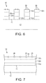
- Fig. 6 illustrates one example of a finished blade 10 achieved by means of the methods described above.
- the backing strip 12 is coated along one edge 11 by the binder layer 32, which forms teeth 42 in this example and gaps 44, and which has abrasive particles 26 embedded in the teeth 42 and exposed at the tips of the teeth.
- the result is a tool blade 10 in which the abrasive particles 26 are presented for working a workpiece, and are securely held in position by the binder layer 32, which acts as an interface between the abrasive particles 26 and the backing strip 12.
- the material of the binder layer 32 can be considered as a functionally graded material.
- the layer 32 has at least one characteristic which changes between the region 32a bound to the backing strip 12 and the region 32c bound to the abrasive particles 26.
- the region 32a is formed to encourage binding with the backing strip 12 and is ductile
- the region 32c is formed to encourage binding with the abrasive particles 26 and is hard.
- the intermediate region 32b provides a buffer for thermal effects.
- Fig. 7 illustrates a further example of a finished blade 10 achieved by means of the methods described above. This example differs from example of Fig. 5 only in that the binder layer 32 is provided continuously along the edge 11 of the strip 12. Each position along the blade will have the binder layer structure described above and will exhibit the properties of enhanced bonding with the backing strip 12, ductility, enhanced bonding with the abrasive particles 26, hardness and intermediate thermal buffering, for the reasons explained above.
- Fig. 8 shows a further example of a finished blade. This differs from the example of Fig. 5 only in that the strip 12 is pre-formed, e.g. by punching, to have tooth roots 46 along its edge.
- the binder layer 32 is built on the roots 46, as described above, to form teeth 42 which have gullets 44 extending into the gaps between the roots 46. This allows various tooth forms to be built on pre-formed tooth roots.
- the binding materials may be used in the form of single materials or combinations of materials.
- one of the binding materials may include a constituent which has a characteristic tuned to the radiation.
- the constituent may have an absorption peak at the wavelength of the illuminating laser light from the source 24.
- the laser 24 may be tuned to the absorption peak. This will promote rapid absorption of energy from the radiation source 24 by the constituent within the binding material, thereby promoting rapid heating within the binding material. This is expected to provide enhanced control of the formation conditions and/or enhanced production rates.
- the abrasive particles may be super abrasive materials such as cubic boron nitride, diamond, tungsten carbide or another super abrasive material. A mixture of abrasive particles of different materials can be used.
- the abrasive particles may be coated prior to their introduction, by means of a coating which promotes binding with the binding layer 32. Examples include coating with a material which promotes wetting of the abrasive particles by the binding material. Coatings may be applied to the abrasive particles by a physical vapour deposition technique or by a chemical vapour deposition technique.
Landscapes
- Engineering & Computer Science (AREA)
- Mechanical Engineering (AREA)
- Chemical & Material Sciences (AREA)
- Materials Engineering (AREA)
- Optics & Photonics (AREA)
- Physics & Mathematics (AREA)
- Metallurgy (AREA)
- Organic Chemistry (AREA)
- Chemical Kinetics & Catalysis (AREA)
- Manufacturing & Machinery (AREA)
- Plasma & Fusion (AREA)
- Polishing Bodies And Polishing Tools (AREA)
- Laminated Bodies (AREA)
- Powder Metallurgy (AREA)
Applications Claiming Priority (1)
| Application Number | Priority Date | Filing Date | Title |
|---|---|---|---|
| GB1512361.5A GB2540385B (en) | 2015-07-15 | 2015-07-15 | Improvements in or relating to tool blades and their manufacture |
Publications (2)
| Publication Number | Publication Date |
|---|---|
| EP3117942A1 true EP3117942A1 (fr) | 2017-01-18 |
| EP3117942B1 EP3117942B1 (fr) | 2018-09-12 |
Family
ID=54013977
Family Applications (1)
| Application Number | Title | Priority Date | Filing Date |
|---|---|---|---|
| EP16175555.8A Active EP3117942B1 (fr) | 2015-07-15 | 2016-06-21 | Lames d'outil et leur fabrication |
Country Status (4)
| Country | Link |
|---|---|
| US (3) | US10730152B2 (fr) |
| EP (1) | EP3117942B1 (fr) |
| JP (1) | JP6914013B2 (fr) |
| GB (1) | GB2540385B (fr) |
Cited By (4)
| Publication number | Priority date | Publication date | Assignee | Title |
|---|---|---|---|---|
| GB2579049A (en) * | 2018-11-16 | 2020-06-10 | C4 Carbides Ltd | Method and apparatus for forming cutting blades |
| WO2021001157A1 (fr) * | 2019-07-02 | 2021-01-07 | WIKUS-Sägenfabrik Wilhelm H. Kullmann GmbH & Co. KG | Outil d'usinage par enlèvement de copeaux sous forme de bande à particules tampon |
| CN114007826A (zh) * | 2019-07-02 | 2022-02-01 | 维克库斯-施特格恩法布里克威廉 H.库尔曼有限责任及两合公司 | 具有带切割颗粒的不对称齿的切削工具 |
| RU2808864C2 (ru) * | 2019-07-02 | 2023-12-05 | Викус-Зегенфабрик Вильхельм Х. Кулльманн Гмбх Унд Ко. Кг | Режущий инструмент в форме ленты с буферными частицами |
Families Citing this family (5)
| Publication number | Priority date | Publication date | Assignee | Title |
|---|---|---|---|---|
| US10486253B2 (en) * | 2017-01-04 | 2019-11-26 | Kennametal Inc. | Metal-cutting tool, in particular a reaming tool and method of making the same |
| JP7012276B2 (ja) * | 2018-09-07 | 2022-01-28 | 石川県 | 砥粒付工具、砥粒付工具の製造方法及び砥粒固着方法 |
| EP3623092A1 (fr) * | 2018-09-11 | 2020-03-18 | Voestalpine Precision Strip GmbH | Lame de scie alternative |
| JP7122232B2 (ja) * | 2018-11-22 | 2022-08-19 | 株式会社アマダ | 鋸工具の製造方法及び鋸工具 |
| CN109623683A (zh) * | 2018-12-28 | 2019-04-16 | 西安增材制造国家研究院有限公司 | 一种基于增材加工的树脂基砂轮制造方法及制造装置 |
Citations (4)
| Publication number | Priority date | Publication date | Assignee | Title |
|---|---|---|---|---|
| GB1513667A (en) * | 1974-09-11 | 1978-06-07 | Engel N | Coated steel product and process of producing the same |
| EP1332822A1 (fr) * | 2002-01-16 | 2003-08-06 | Tyrolit Schleifmittelwerke Swarovski KG | Scie à ruban |
| EP2138263A2 (fr) * | 2008-06-23 | 2009-12-30 | The Stanley Works | Procédé de fabrication d'une lame |
| CN105562825A (zh) * | 2015-12-24 | 2016-05-11 | 中南大学 | 金属结合剂复杂型面金刚石锯片及其3d打印制作工艺 |
Family Cites Families (60)
| Publication number | Priority date | Publication date | Assignee | Title |
|---|---|---|---|---|
| US2065041A (en) * | 1936-03-06 | 1936-12-22 | Norton Co | Saw tooth |
| US2442153A (en) * | 1946-04-23 | 1948-05-25 | Norton Co | Band saw with diamond abrasive teeth |
| US2589357A (en) * | 1949-04-13 | 1952-03-18 | Super Cut | Diamond type tooth for rotary stone cutting saws |
| US2718162A (en) * | 1952-06-23 | 1955-09-20 | Belmont D Smith | Bucket tooth repointing |
| US3063310A (en) * | 1959-10-15 | 1962-11-13 | Continental Machines | Metal cutting saw bands and blades and method of making the same |
| US3089945A (en) * | 1960-11-07 | 1963-05-14 | Continental Machines | Band saw blade stock and method of making the same |
| US3261384A (en) * | 1965-05-19 | 1966-07-19 | George A Henderson | Circular saw |
| US3528465A (en) * | 1965-06-01 | 1970-09-15 | Herbert A Omley | Saw with ceramic cutting bodies |
| US3704576A (en) * | 1971-06-09 | 1972-12-05 | Univ Iowa State Res Found | Fruit and vegetable harvesting device |
| DE2323243C3 (de) * | 1973-05-09 | 1980-02-28 | Robert Bosch Gmbh, 7000 Stuttgart | Verfahren zur Herstellung einer verschleißfesten Hartmetallschicht auf einem Metallgegenstand, insbesondere auf der Schneide eines Stahl-Sägeblattes |
| US4097711A (en) * | 1976-09-16 | 1978-06-27 | Ingersoll-Rand Company | Roller shell hard coating |
| US4837417A (en) * | 1983-12-05 | 1989-06-06 | Funk Charles F | Method of hard-facing a metal surface |
| DE3738492A1 (de) * | 1987-11-12 | 1989-05-24 | Wagner Maschf Gustav | Verfahren zum befestigen von hss-schneiden oder dgl. an einem werkzeug-tragelement, sowie nach diesem verfahren hergestellte werkzeuge |
| US4919974A (en) * | 1989-01-12 | 1990-04-24 | Ford Motor Company | Making diamond composite coated cutting tools |
| JPH03221281A (ja) * | 1990-08-27 | 1991-09-30 | Osaka Diamond Ind Co Ltd | カッターセグメントの溶接方法 |
| DE9102389U1 (fr) | 1991-02-28 | 1991-05-16 | Galeski, Peter, 5439 Gemuenden, De | |
| US5249485A (en) * | 1991-12-31 | 1993-10-05 | Sandvik Ab | Bandsaw blade and method of manufacturing same |
| JP2698523B2 (ja) * | 1992-12-25 | 1998-01-19 | 株式会社日本アルミ | 超砥粒砥石及びその製造方法 |
| JPH0825151A (ja) * | 1994-07-19 | 1996-01-30 | Shimizu Shokuhin Kk | 切削工具及びその製造方法 |
| DE19533836B4 (de) * | 1995-09-13 | 2005-07-21 | Ernst Winter & Sohn Diamantwerkzeuge Gmbh & Co. | Profilschleifscheibe und Verfahren und Vorrichtung zur Herstellung |
| ES2143300T3 (es) * | 1996-03-15 | 2000-05-01 | Norton Co | Herramienta de corte abrasiva con una unica capa metalica, provista de una superficie de corte perfilada. |
| US20040112359A1 (en) * | 1997-04-04 | 2004-06-17 | Chien-Min Sung | Brazed diamond tools and methods for making the same |
| US9221154B2 (en) * | 1997-04-04 | 2015-12-29 | Chien-Min Sung | Diamond tools and methods for making the same |
| US7124753B2 (en) * | 1997-04-04 | 2006-10-24 | Chien-Min Sung | Brazed diamond tools and methods for making the same |
| EP1013379A4 (fr) * | 1997-07-16 | 2007-05-09 | Ishizuka Res Inst Ltd | Materiau composite stratifie contenant du diamant et procede de fabrication de ce materiau |
| US6298762B1 (en) * | 1998-08-06 | 2001-10-09 | Larue John D. | Saw blade with inserted multi-tooth arcs |
| US6206115B1 (en) * | 1998-08-21 | 2001-03-27 | Baker Hughes Incorporated | Steel tooth bit with extra-thick hardfacing |
| ES2247964T3 (es) * | 1999-02-04 | 2006-03-16 | Ricoh Company, Ltd. | Sierra de alambres con alambre abrasivo y procedimiento para fabricar el alambre abrasivo. |
| US6615936B1 (en) * | 2000-04-19 | 2003-09-09 | Smith International, Inc. | Method for applying hardfacing to a substrate and its application to construction of milled tooth drill bits |
| US6706319B2 (en) * | 2001-12-05 | 2004-03-16 | Siemens Westinghouse Power Corporation | Mixed powder deposition of components for wear, erosion and abrasion resistant applications |
| JP3732178B2 (ja) * | 2002-12-27 | 2006-01-05 | 株式会社ノリタケスーパーアブレーシブ | ワイヤソー及びその製造方法 |
| KR100615709B1 (ko) * | 2003-11-26 | 2006-08-25 | 신한다이아몬드공업 주식회사 | 연마공구 및 절삭공구의 제조방법 및 그 공구 |
| KR100572669B1 (ko) | 2004-02-09 | 2006-04-24 | 신한다이아몬드공업 주식회사 | 복수의 지립층이 형성된 절삭 공구 및 그 제조 방법 |
| US8096221B2 (en) * | 2004-02-18 | 2012-01-17 | Societe D'exploitation Tarrerias Bonjean | Method of producing a cutting blade and cutting blade thus produced |
| DE102004010781B4 (de) * | 2004-03-05 | 2014-09-04 | Dolmar Gmbh | Betonsägekette und Verfahren zur Herstellung einer Sägekette |
| JP4711693B2 (ja) * | 2005-02-04 | 2011-06-29 | 京セラ株式会社 | バンドソー型切断機と、それを用いた半導体鋳塊切断方法 |
| US7524345B2 (en) * | 2005-02-22 | 2009-04-28 | Saint-Gobain Abrasives, Inc. | Rapid tooling system and methods for manufacturing abrasive articles |
| DE102006001816B4 (de) * | 2006-01-13 | 2008-05-08 | WIKUS-Sägenfabrik Wilhelm H. Kullmann GmbH & Co. KG | Sägeblatt mit einem Grundkörper und Zähnen mit einer Schneide mit einer Verschleißschutzschicht |
| GB2443252B (en) * | 2006-10-24 | 2010-11-17 | C4 Carbides Ltd | Blade |
| JP5428096B2 (ja) | 2006-11-24 | 2014-02-26 | エリコン・トレーディング・アクチェンゲゼルシャフト,トリュープバッハ | 帯鋸、および帯鋸を製造する方法 |
| CA2686070A1 (fr) * | 2008-11-18 | 2010-05-18 | Pacific Saw & Knife Company Llc | Lame de scie circulaire munie d'une couche d'isolation thermique |
| US9044841B2 (en) * | 2008-11-19 | 2015-06-02 | Saint-Gobain Abrasives, Inc. | Abrasive articles and methods of forming |
| JP5051399B2 (ja) * | 2009-05-01 | 2012-10-17 | 信越化学工業株式会社 | 外周切断刃の製造方法及び外周切断刃製造用治具 |
| CN102770240A (zh) * | 2009-11-05 | 2012-11-07 | 株式会社中村超硬 | 超磨粒固定式线状锯和超磨粒固定式线状锯的制造方法 |
| JP5229270B2 (ja) * | 2010-05-14 | 2013-07-03 | 豊田合成株式会社 | Iii族窒化物半導体発光素子の製造方法 |
| TW201507812A (zh) * | 2010-12-30 | 2015-03-01 | Saint Gobain Abrasives Inc | 磨料物品及形成方法 |
| DE102011005034A1 (de) | 2011-03-03 | 2012-09-06 | Robert Bosch Gmbh | Verfahren zur Herstellung von zumindest einem Schneidstrangsegment eines Schneidstrangs |
| EP2495062A1 (fr) * | 2011-03-04 | 2012-09-05 | NV Bekaert SA | Bille de sciage |
| PT2680998T (pt) * | 2011-03-04 | 2017-03-01 | Bekaert Sa Nv | Método para produzir uma pérola para serragem |
| CN202079511U (zh) * | 2011-05-06 | 2011-12-21 | 福建万龙金刚石工具有限公司 | 磨料多层定向排布的金刚石锯片 |
| CN107263340A (zh) * | 2011-09-16 | 2017-10-20 | 圣戈班磨料磨具有限公司 | 研磨制品和形成方法 |
| US10462963B2 (en) * | 2012-03-06 | 2019-11-05 | Kondex Corporation | Laser clad cutting edge for agricultural cutting components |
| EP2662168A1 (fr) * | 2012-05-08 | 2013-11-13 | WIKUS-Sägenfabrik Wilhelm H. Kullmann GmbH & Co. KG | Lame de scie avec élément de coupe fabriqué en métallurgie des poudres |
| TWI477343B (zh) * | 2012-06-29 | 2015-03-21 | Saint Gobain Abrasives Inc | 研磨物品及形成方法 |
| WO2014063910A1 (fr) | 2012-10-24 | 2014-05-01 | Nv Bekaert Sa | Fil à scier abrasif fixe plat |
| AU2014342154A1 (en) * | 2013-10-31 | 2016-06-02 | Vermeer Manufacturing Company | Hardfacing incorporating carbide particles |
| DE102014203459A1 (de) * | 2014-02-26 | 2015-09-10 | Gebr. Brasseler Gmbh & Co. Kg | Verfahren zur Herstellung eines Dentalinstruments oder medizinischen Instruments |
| MX355451B (es) * | 2014-06-20 | 2018-04-18 | Velo3D Inc | Aparatos, sistemas y metodos para impresion tridimensional. |
| US10648051B2 (en) * | 2015-04-24 | 2020-05-12 | Kondex Corporation | Reciprocating cutting blade with cladding |
| DE102015208781A1 (de) * | 2015-05-12 | 2016-11-17 | MTU Aero Engines AG | Kombination von Schaufelspitzenpanzerung und Erosionsschutzschicht sowie Verfahren zur Herstellung derselben |
-
2015
- 2015-07-15 GB GB1512361.5A patent/GB2540385B/en active Active
-
2016
- 2016-06-21 EP EP16175555.8A patent/EP3117942B1/fr active Active
- 2016-07-11 US US15/206,491 patent/US10730152B2/en active Active
- 2016-07-14 JP JP2016139353A patent/JP6914013B2/ja active Active
-
2019
- 2019-11-13 US US16/682,384 patent/US11135689B2/en active Active
-
2020
- 2020-06-16 US US16/902,952 patent/US20200306901A1/en active Pending
Patent Citations (4)
| Publication number | Priority date | Publication date | Assignee | Title |
|---|---|---|---|---|
| GB1513667A (en) * | 1974-09-11 | 1978-06-07 | Engel N | Coated steel product and process of producing the same |
| EP1332822A1 (fr) * | 2002-01-16 | 2003-08-06 | Tyrolit Schleifmittelwerke Swarovski KG | Scie à ruban |
| EP2138263A2 (fr) * | 2008-06-23 | 2009-12-30 | The Stanley Works | Procédé de fabrication d'une lame |
| CN105562825A (zh) * | 2015-12-24 | 2016-05-11 | 中南大学 | 金属结合剂复杂型面金刚石锯片及其3d打印制作工艺 |
Cited By (8)
| Publication number | Priority date | Publication date | Assignee | Title |
|---|---|---|---|---|
| GB2579049A (en) * | 2018-11-16 | 2020-06-10 | C4 Carbides Ltd | Method and apparatus for forming cutting blades |
| GB2579049B (en) * | 2018-11-16 | 2021-03-31 | C4 Carbides Ltd | Method and apparatus for forming cutting blades |
| US11819921B2 (en) | 2018-11-16 | 2023-11-21 | C4 Carbides Limited | Method and apparatus for forming cutting blades |
| WO2021001157A1 (fr) * | 2019-07-02 | 2021-01-07 | WIKUS-Sägenfabrik Wilhelm H. Kullmann GmbH & Co. KG | Outil d'usinage par enlèvement de copeaux sous forme de bande à particules tampon |
| CN113993675A (zh) * | 2019-07-02 | 2022-01-28 | 维克库斯-施特格恩法布里克威廉 H.库尔曼有限责任及两合公司 | 具有缓冲颗粒的带形切削工具 |
| CN114007826A (zh) * | 2019-07-02 | 2022-02-01 | 维克库斯-施特格恩法布里克威廉 H.库尔曼有限责任及两合公司 | 具有带切割颗粒的不对称齿的切削工具 |
| CN113993675B (zh) * | 2019-07-02 | 2023-08-04 | 维克库斯-施特格恩法布里克威廉 H.库尔曼有限责任及两合公司 | 具有缓冲颗粒的带形切削工具 |
| RU2808864C2 (ru) * | 2019-07-02 | 2023-12-05 | Викус-Зегенфабрик Вильхельм Х. Кулльманн Гмбх Унд Ко. Кг | Режущий инструмент в форме ленты с буферными частицами |
Also Published As
| Publication number | Publication date |
|---|---|
| GB2540385B (en) | 2017-10-11 |
| JP2017052087A (ja) | 2017-03-16 |
| GB2540385A (en) | 2017-01-18 |
| GB201512361D0 (en) | 2015-08-19 |
| US20200306901A1 (en) | 2020-10-01 |
| JP6914013B2 (ja) | 2021-08-04 |
| US10730152B2 (en) | 2020-08-04 |
| EP3117942B1 (fr) | 2018-09-12 |
| US20200086407A1 (en) | 2020-03-19 |
| US20170014959A1 (en) | 2017-01-19 |
| US11135689B2 (en) | 2021-10-05 |
Similar Documents
| Publication | Publication Date | Title |
|---|---|---|
| US20200306901A1 (en) | Tool blades | |
| EP3117943B1 (fr) | Lames d'outil et leur fabrication | |
| US9764442B2 (en) | Cutting/polishing tool and manufacturing method thereof | |
| KR101729804B1 (ko) | 절삭 공구 | |
| US20160279734A1 (en) | Component and method for fabricating a component | |
| EP2522452A1 (fr) | Chauffage combiné destinée au chauffage de la pièce par induction et au brasage laser pour appliquer un revêtement | |
| JP2017052087A5 (ja) | 工具刃および工具刃の製造方法 | |
| EP3525972B1 (fr) | Procédé de fabrication d'une lame dentée et appareil pour la fabrication d'une telle lame | |
| CN114555278A (zh) | 熔覆的工具和制造熔覆的工具的方法 | |
| US20160368096A1 (en) | Method for producing a dental or medical instrument | |
| JP7012276B2 (ja) | 砥粒付工具、砥粒付工具の製造方法及び砥粒固着方法 | |
| US20160367337A1 (en) | Dental instrument | |
| JP2020063478A (ja) | 硬化層の積層方法及び積層造形物の製造方法 | |
| JP6761596B2 (ja) | 複合材料からなる切削工具 | |
| Stompe et al. | Concept for performance-enhancement of ultra-precision dicing for bulk hard and brittle materials in micro applications by laser dressing | |
| JP6039477B2 (ja) | 切削工具 | |
| CN113993675B (zh) | 具有缓冲颗粒的带形切削工具 | |
| JP6148101B2 (ja) | 切削工具 | |
| US1371008A (en) | Method of forming saw-teeth | |
| US461509A (en) | Art of manufacturing saws |
Legal Events
| Date | Code | Title | Description |
|---|---|---|---|
| PUAI | Public reference made under article 153(3) epc to a published international application that has entered the european phase |
Free format text: ORIGINAL CODE: 0009012 |
|
| STAA | Information on the status of an ep patent application or granted ep patent |
Free format text: STATUS: THE APPLICATION HAS BEEN PUBLISHED |
|
| AK | Designated contracting states |
Kind code of ref document: A1 Designated state(s): AL AT BE BG CH CY CZ DE DK EE ES FI FR GB GR HR HU IE IS IT LI LT LU LV MC MK MT NL NO PL PT RO RS SE SI SK SM TR |
|
| AX | Request for extension of the european patent |
Extension state: BA ME |
|
| 17P | Request for examination filed |
Effective date: 20170502 |
|
| RBV | Designated contracting states (corrected) |
Designated state(s): AL AT BE BG CH CY CZ DE DK EE ES FI FR GB GR HR HU IE IS IT LI LT LU LV MC MK MT NL NO PL PT RO RS SE SI SK SM TR |
|
| STAA | Information on the status of an ep patent application or granted ep patent |
Free format text: STATUS: REQUEST FOR EXAMINATION WAS MADE |
|
| GRAP | Despatch of communication of intention to grant a patent |
Free format text: ORIGINAL CODE: EPIDOSNIGR1 |
|
| STAA | Information on the status of an ep patent application or granted ep patent |
Free format text: STATUS: GRANT OF PATENT IS INTENDED |
|
| INTG | Intention to grant announced |
Effective date: 20180409 |
|
| GRAJ | Information related to disapproval of communication of intention to grant by the applicant or resumption of examination proceedings by the epo deleted |
Free format text: ORIGINAL CODE: EPIDOSDIGR1 |
|
| GRAP | Despatch of communication of intention to grant a patent |
Free format text: ORIGINAL CODE: EPIDOSNIGR1 |
|
| GRAS | Grant fee paid |
Free format text: ORIGINAL CODE: EPIDOSNIGR3 |
|
| GRAA | (expected) grant |
Free format text: ORIGINAL CODE: 0009210 |
|
| STAA | Information on the status of an ep patent application or granted ep patent |
Free format text: STATUS: THE PATENT HAS BEEN GRANTED |
|
| INTG | Intention to grant announced |
Effective date: 20180726 |
|
| AK | Designated contracting states |
Kind code of ref document: B1 Designated state(s): AL AT BE BG CH CY CZ DE DK EE ES FI FR GB GR HR HU IE IS IT LI LT LU LV MC MK MT NL NO PL PT RO RS SE SI SK SM TR |
|
| REG | Reference to a national code |
Ref country code: GB Ref legal event code: FG4D |
|
| REG | Reference to a national code |
Ref country code: CH Ref legal event code: EP |
|
| REG | Reference to a national code |
Ref country code: IE Ref legal event code: FG4D |
|
| REG | Reference to a national code |
Ref country code: DE Ref legal event code: R096 Ref document number: 602016005465 Country of ref document: DE |
|
| REG | Reference to a national code |
Ref country code: AT Ref legal event code: REF Ref document number: 1039955 Country of ref document: AT Kind code of ref document: T Effective date: 20181015 |
|
| REG | Reference to a national code |
Ref country code: NL Ref legal event code: MP Effective date: 20180912 |
|
| REG | Reference to a national code |
Ref country code: LT Ref legal event code: MG4D |
|
| PG25 | Lapsed in a contracting state [announced via postgrant information from national office to epo] |
Ref country code: SE Free format text: LAPSE BECAUSE OF FAILURE TO SUBMIT A TRANSLATION OF THE DESCRIPTION OR TO PAY THE FEE WITHIN THE PRESCRIBED TIME-LIMIT Effective date: 20180912 Ref country code: GR Free format text: LAPSE BECAUSE OF FAILURE TO SUBMIT A TRANSLATION OF THE DESCRIPTION OR TO PAY THE FEE WITHIN THE PRESCRIBED TIME-LIMIT Effective date: 20181213 Ref country code: RS Free format text: LAPSE BECAUSE OF FAILURE TO SUBMIT A TRANSLATION OF THE DESCRIPTION OR TO PAY THE FEE WITHIN THE PRESCRIBED TIME-LIMIT Effective date: 20180912 Ref country code: NO Free format text: LAPSE BECAUSE OF FAILURE TO SUBMIT A TRANSLATION OF THE DESCRIPTION OR TO PAY THE FEE WITHIN THE PRESCRIBED TIME-LIMIT Effective date: 20181212 Ref country code: FI Free format text: LAPSE BECAUSE OF FAILURE TO SUBMIT A TRANSLATION OF THE DESCRIPTION OR TO PAY THE FEE WITHIN THE PRESCRIBED TIME-LIMIT Effective date: 20180912 Ref country code: LT Free format text: LAPSE BECAUSE OF FAILURE TO SUBMIT A TRANSLATION OF THE DESCRIPTION OR TO PAY THE FEE WITHIN THE PRESCRIBED TIME-LIMIT Effective date: 20180912 Ref country code: BG Free format text: LAPSE BECAUSE OF FAILURE TO SUBMIT A TRANSLATION OF THE DESCRIPTION OR TO PAY THE FEE WITHIN THE PRESCRIBED TIME-LIMIT Effective date: 20181212 |
|
| PG25 | Lapsed in a contracting state [announced via postgrant information from national office to epo] |
Ref country code: LV Free format text: LAPSE BECAUSE OF FAILURE TO SUBMIT A TRANSLATION OF THE DESCRIPTION OR TO PAY THE FEE WITHIN THE PRESCRIBED TIME-LIMIT Effective date: 20180912 Ref country code: AL Free format text: LAPSE BECAUSE OF FAILURE TO SUBMIT A TRANSLATION OF THE DESCRIPTION OR TO PAY THE FEE WITHIN THE PRESCRIBED TIME-LIMIT Effective date: 20180912 Ref country code: HR Free format text: LAPSE BECAUSE OF FAILURE TO SUBMIT A TRANSLATION OF THE DESCRIPTION OR TO PAY THE FEE WITHIN THE PRESCRIBED TIME-LIMIT Effective date: 20180912 |
|
| REG | Reference to a national code |
Ref country code: AT Ref legal event code: MK05 Ref document number: 1039955 Country of ref document: AT Kind code of ref document: T Effective date: 20180912 |
|
| PG25 | Lapsed in a contracting state [announced via postgrant information from national office to epo] |
Ref country code: EE Free format text: LAPSE BECAUSE OF FAILURE TO SUBMIT A TRANSLATION OF THE DESCRIPTION OR TO PAY THE FEE WITHIN THE PRESCRIBED TIME-LIMIT Effective date: 20180912 Ref country code: PL Free format text: LAPSE BECAUSE OF FAILURE TO SUBMIT A TRANSLATION OF THE DESCRIPTION OR TO PAY THE FEE WITHIN THE PRESCRIBED TIME-LIMIT Effective date: 20180912 Ref country code: RO Free format text: LAPSE BECAUSE OF FAILURE TO SUBMIT A TRANSLATION OF THE DESCRIPTION OR TO PAY THE FEE WITHIN THE PRESCRIBED TIME-LIMIT Effective date: 20180912 Ref country code: CZ Free format text: LAPSE BECAUSE OF FAILURE TO SUBMIT A TRANSLATION OF THE DESCRIPTION OR TO PAY THE FEE WITHIN THE PRESCRIBED TIME-LIMIT Effective date: 20180912 Ref country code: NL Free format text: LAPSE BECAUSE OF FAILURE TO SUBMIT A TRANSLATION OF THE DESCRIPTION OR TO PAY THE FEE WITHIN THE PRESCRIBED TIME-LIMIT Effective date: 20180912 Ref country code: ES Free format text: LAPSE BECAUSE OF FAILURE TO SUBMIT A TRANSLATION OF THE DESCRIPTION OR TO PAY THE FEE WITHIN THE PRESCRIBED TIME-LIMIT Effective date: 20180912 Ref country code: IS Free format text: LAPSE BECAUSE OF FAILURE TO SUBMIT A TRANSLATION OF THE DESCRIPTION OR TO PAY THE FEE WITHIN THE PRESCRIBED TIME-LIMIT Effective date: 20190112 Ref country code: AT Free format text: LAPSE BECAUSE OF FAILURE TO SUBMIT A TRANSLATION OF THE DESCRIPTION OR TO PAY THE FEE WITHIN THE PRESCRIBED TIME-LIMIT Effective date: 20180912 |
|
| PG25 | Lapsed in a contracting state [announced via postgrant information from national office to epo] |
Ref country code: SK Free format text: LAPSE BECAUSE OF FAILURE TO SUBMIT A TRANSLATION OF THE DESCRIPTION OR TO PAY THE FEE WITHIN THE PRESCRIBED TIME-LIMIT Effective date: 20180912 Ref country code: PT Free format text: LAPSE BECAUSE OF FAILURE TO SUBMIT A TRANSLATION OF THE DESCRIPTION OR TO PAY THE FEE WITHIN THE PRESCRIBED TIME-LIMIT Effective date: 20190112 Ref country code: SM Free format text: LAPSE BECAUSE OF FAILURE TO SUBMIT A TRANSLATION OF THE DESCRIPTION OR TO PAY THE FEE WITHIN THE PRESCRIBED TIME-LIMIT Effective date: 20180912 |
|
| REG | Reference to a national code |
Ref country code: DE Ref legal event code: R097 Ref document number: 602016005465 Country of ref document: DE |
|
| PLBE | No opposition filed within time limit |
Free format text: ORIGINAL CODE: 0009261 |
|
| STAA | Information on the status of an ep patent application or granted ep patent |
Free format text: STATUS: NO OPPOSITION FILED WITHIN TIME LIMIT |
|
| PG25 | Lapsed in a contracting state [announced via postgrant information from national office to epo] |
Ref country code: DK Free format text: LAPSE BECAUSE OF FAILURE TO SUBMIT A TRANSLATION OF THE DESCRIPTION OR TO PAY THE FEE WITHIN THE PRESCRIBED TIME-LIMIT Effective date: 20180912 |
|
| 26N | No opposition filed |
Effective date: 20190613 |
|
| PG25 | Lapsed in a contracting state [announced via postgrant information from national office to epo] |
Ref country code: SI Free format text: LAPSE BECAUSE OF FAILURE TO SUBMIT A TRANSLATION OF THE DESCRIPTION OR TO PAY THE FEE WITHIN THE PRESCRIBED TIME-LIMIT Effective date: 20180912 |
|
| PG25 | Lapsed in a contracting state [announced via postgrant information from national office to epo] |
Ref country code: MC Free format text: LAPSE BECAUSE OF FAILURE TO SUBMIT A TRANSLATION OF THE DESCRIPTION OR TO PAY THE FEE WITHIN THE PRESCRIBED TIME-LIMIT Effective date: 20180912 |
|
| REG | Reference to a national code |
Ref country code: CH Ref legal event code: PL |
|
| REG | Reference to a national code |
Ref country code: BE Ref legal event code: MM Effective date: 20190630 |
|
| PG25 | Lapsed in a contracting state [announced via postgrant information from national office to epo] |
Ref country code: TR Free format text: LAPSE BECAUSE OF FAILURE TO SUBMIT A TRANSLATION OF THE DESCRIPTION OR TO PAY THE FEE WITHIN THE PRESCRIBED TIME-LIMIT Effective date: 20180912 |
|
| PG25 | Lapsed in a contracting state [announced via postgrant information from national office to epo] |
Ref country code: IE Free format text: LAPSE BECAUSE OF NON-PAYMENT OF DUE FEES Effective date: 20190621 |
|
| PG25 | Lapsed in a contracting state [announced via postgrant information from national office to epo] |
Ref country code: BE Free format text: LAPSE BECAUSE OF NON-PAYMENT OF DUE FEES Effective date: 20190630 Ref country code: CH Free format text: LAPSE BECAUSE OF NON-PAYMENT OF DUE FEES Effective date: 20190630 Ref country code: LI Free format text: LAPSE BECAUSE OF NON-PAYMENT OF DUE FEES Effective date: 20190630 Ref country code: LU Free format text: LAPSE BECAUSE OF NON-PAYMENT OF DUE FEES Effective date: 20190621 |
|
| PG25 | Lapsed in a contracting state [announced via postgrant information from national office to epo] |
Ref country code: CY Free format text: LAPSE BECAUSE OF FAILURE TO SUBMIT A TRANSLATION OF THE DESCRIPTION OR TO PAY THE FEE WITHIN THE PRESCRIBED TIME-LIMIT Effective date: 20180912 |
|
| PG25 | Lapsed in a contracting state [announced via postgrant information from national office to epo] |
Ref country code: HU Free format text: LAPSE BECAUSE OF FAILURE TO SUBMIT A TRANSLATION OF THE DESCRIPTION OR TO PAY THE FEE WITHIN THE PRESCRIBED TIME-LIMIT; INVALID AB INITIO Effective date: 20160621 Ref country code: MT Free format text: LAPSE BECAUSE OF FAILURE TO SUBMIT A TRANSLATION OF THE DESCRIPTION OR TO PAY THE FEE WITHIN THE PRESCRIBED TIME-LIMIT Effective date: 20180912 |
|
| PG25 | Lapsed in a contracting state [announced via postgrant information from national office to epo] |
Ref country code: MK Free format text: LAPSE BECAUSE OF FAILURE TO SUBMIT A TRANSLATION OF THE DESCRIPTION OR TO PAY THE FEE WITHIN THE PRESCRIBED TIME-LIMIT Effective date: 20180912 |
|
| P01 | Opt-out of the competence of the unified patent court (upc) registered |
Effective date: 20230427 |
|
| PGFP | Annual fee paid to national office [announced via postgrant information from national office to epo] |
Ref country code: FR Payment date: 20230628 Year of fee payment: 8 Ref country code: DE Payment date: 20230620 Year of fee payment: 8 |
|
| PGFP | Annual fee paid to national office [announced via postgrant information from national office to epo] |
Ref country code: IT Payment date: 20230621 Year of fee payment: 8 Ref country code: GB Payment date: 20230427 Year of fee payment: 8 |