EP3115678B1 - Method of making a vehicle light and related vehicle light - Google Patents
Method of making a vehicle light and related vehicle light Download PDFInfo
- Publication number
- EP3115678B1 EP3115678B1 EP16172044.6A EP16172044A EP3115678B1 EP 3115678 B1 EP3115678 B1 EP 3115678B1 EP 16172044 A EP16172044 A EP 16172044A EP 3115678 B1 EP3115678 B1 EP 3115678B1
- Authority
- EP
- European Patent Office
- Prior art keywords
- lenticular body
- light
- redirection
- welding
- side wall
- Prior art date
- Legal status (The legal status is an assumption and is not a legal conclusion. Google has not performed a legal analysis and makes no representation as to the accuracy of the status listed.)
- Active
Links
Images


Classifications
-
- F—MECHANICAL ENGINEERING; LIGHTING; HEATING; WEAPONS; BLASTING
- F21—LIGHTING
- F21K—NON-ELECTRIC LIGHT SOURCES USING LUMINESCENCE; LIGHT SOURCES USING ELECTROCHEMILUMINESCENCE; LIGHT SOURCES USING CHARGES OF COMBUSTIBLE MATERIAL; LIGHT SOURCES USING SEMICONDUCTOR DEVICES AS LIGHT-GENERATING ELEMENTS; LIGHT SOURCES NOT OTHERWISE PROVIDED FOR
- F21K9/00—Light sources using semiconductor devices as light-generating elements, e.g. using light-emitting diodes [LED] or lasers
- F21K9/90—Methods of manufacture
-
- F—MECHANICAL ENGINEERING; LIGHTING; HEATING; WEAPONS; BLASTING
- F21—LIGHTING
- F21S—NON-PORTABLE LIGHTING DEVICES; SYSTEMS THEREOF; VEHICLE LIGHTING DEVICES SPECIALLY ADAPTED FOR VEHICLE EXTERIORS
- F21S41/00—Illuminating devices specially adapted for vehicle exteriors, e.g. headlamps
- F21S41/20—Illuminating devices specially adapted for vehicle exteriors, e.g. headlamps characterised by refractors, transparent cover plates, light guides or filters
- F21S41/29—Attachment thereof
-
- B—PERFORMING OPERATIONS; TRANSPORTING
- B29—WORKING OF PLASTICS; WORKING OF SUBSTANCES IN A PLASTIC STATE IN GENERAL
- B29C—SHAPING OR JOINING OF PLASTICS; SHAPING OF MATERIAL IN A PLASTIC STATE, NOT OTHERWISE PROVIDED FOR; AFTER-TREATMENT OF THE SHAPED PRODUCTS, e.g. REPAIRING
- B29C65/00—Joining or sealing of preformed parts, e.g. welding of plastics materials; Apparatus therefor
- B29C65/02—Joining or sealing of preformed parts, e.g. welding of plastics materials; Apparatus therefor by heating, with or without pressure
- B29C65/14—Joining or sealing of preformed parts, e.g. welding of plastics materials; Apparatus therefor by heating, with or without pressure using wave energy, i.e. electromagnetic radiation, or particle radiation
- B29C65/16—Laser beams
- B29C65/1629—Laser beams characterised by the way of heating the interface
- B29C65/1635—Laser beams characterised by the way of heating the interface at least passing through one of the parts to be joined, i.e. laser transmission welding
-
- B—PERFORMING OPERATIONS; TRANSPORTING
- B29—WORKING OF PLASTICS; WORKING OF SUBSTANCES IN A PLASTIC STATE IN GENERAL
- B29C—SHAPING OR JOINING OF PLASTICS; SHAPING OF MATERIAL IN A PLASTIC STATE, NOT OTHERWISE PROVIDED FOR; AFTER-TREATMENT OF THE SHAPED PRODUCTS, e.g. REPAIRING
- B29C65/00—Joining or sealing of preformed parts, e.g. welding of plastics materials; Apparatus therefor
- B29C65/02—Joining or sealing of preformed parts, e.g. welding of plastics materials; Apparatus therefor by heating, with or without pressure
- B29C65/14—Joining or sealing of preformed parts, e.g. welding of plastics materials; Apparatus therefor by heating, with or without pressure using wave energy, i.e. electromagnetic radiation, or particle radiation
- B29C65/16—Laser beams
- B29C65/1629—Laser beams characterised by the way of heating the interface
- B29C65/1664—Laser beams characterised by the way of heating the interface making use of several radiators
- B29C65/1667—Laser beams characterised by the way of heating the interface making use of several radiators at the same time, i.e. simultaneous laser welding
-
- B—PERFORMING OPERATIONS; TRANSPORTING
- B29—WORKING OF PLASTICS; WORKING OF SUBSTANCES IN A PLASTIC STATE IN GENERAL
- B29C—SHAPING OR JOINING OF PLASTICS; SHAPING OF MATERIAL IN A PLASTIC STATE, NOT OTHERWISE PROVIDED FOR; AFTER-TREATMENT OF THE SHAPED PRODUCTS, e.g. REPAIRING
- B29C65/00—Joining or sealing of preformed parts, e.g. welding of plastics materials; Apparatus therefor
- B29C65/02—Joining or sealing of preformed parts, e.g. welding of plastics materials; Apparatus therefor by heating, with or without pressure
- B29C65/14—Joining or sealing of preformed parts, e.g. welding of plastics materials; Apparatus therefor by heating, with or without pressure using wave energy, i.e. electromagnetic radiation, or particle radiation
- B29C65/16—Laser beams
- B29C65/1687—Laser beams making use of light guides
- B29C65/169—Laser beams making use of light guides being a part of the joined article
-
- B—PERFORMING OPERATIONS; TRANSPORTING
- B29—WORKING OF PLASTICS; WORKING OF SUBSTANCES IN A PLASTIC STATE IN GENERAL
- B29C—SHAPING OR JOINING OF PLASTICS; SHAPING OF MATERIAL IN A PLASTIC STATE, NOT OTHERWISE PROVIDED FOR; AFTER-TREATMENT OF THE SHAPED PRODUCTS, e.g. REPAIRING
- B29C66/00—General aspects of processes or apparatus for joining preformed parts
- B29C66/01—General aspects dealing with the joint area or with the area to be joined
- B29C66/05—Particular design of joint configurations
- B29C66/301—Three-dimensional joints, i.e. the joined area being substantially non-flat
-
- B—PERFORMING OPERATIONS; TRANSPORTING
- B29—WORKING OF PLASTICS; WORKING OF SUBSTANCES IN A PLASTIC STATE IN GENERAL
- B29C—SHAPING OR JOINING OF PLASTICS; SHAPING OF MATERIAL IN A PLASTIC STATE, NOT OTHERWISE PROVIDED FOR; AFTER-TREATMENT OF THE SHAPED PRODUCTS, e.g. REPAIRING
- B29C66/00—General aspects of processes or apparatus for joining preformed parts
- B29C66/50—General aspects of joining tubular articles; General aspects of joining long products, i.e. bars or profiled elements; General aspects of joining single elements to tubular articles, hollow articles or bars; General aspects of joining several hollow-preforms to form hollow or tubular articles
- B29C66/51—Joining tubular articles, profiled elements or bars; Joining single elements to tubular articles, hollow articles or bars; Joining several hollow-preforms to form hollow or tubular articles
- B29C66/54—Joining several hollow-preforms, e.g. half-shells, to form hollow articles, e.g. for making balls, containers; Joining several hollow-preforms, e.g. half-cylinders, to form tubular articles
- B29C66/542—Joining several hollow-preforms, e.g. half-shells, to form hollow articles, e.g. for making balls, containers; Joining several hollow-preforms, e.g. half-cylinders, to form tubular articles joining hollow covers or hollow bottoms to open ends of container bodies
-
- F—MECHANICAL ENGINEERING; LIGHTING; HEATING; WEAPONS; BLASTING
- F21—LIGHTING
- F21V—FUNCTIONAL FEATURES OR DETAILS OF LIGHTING DEVICES OR SYSTEMS THEREOF; STRUCTURAL COMBINATIONS OF LIGHTING DEVICES WITH OTHER ARTICLES, NOT OTHERWISE PROVIDED FOR
- F21V17/00—Fastening of component parts of lighting devices, e.g. shades, globes, refractors, reflectors, filters, screens, grids or protective cages
- F21V17/10—Fastening of component parts of lighting devices, e.g. shades, globes, refractors, reflectors, filters, screens, grids or protective cages characterised by specific fastening means or way of fastening
- F21V17/101—Fastening of component parts of lighting devices, e.g. shades, globes, refractors, reflectors, filters, screens, grids or protective cages characterised by specific fastening means or way of fastening permanently, e.g. welding, gluing or riveting
-
- F—MECHANICAL ENGINEERING; LIGHTING; HEATING; WEAPONS; BLASTING
- F21—LIGHTING
- F21V—FUNCTIONAL FEATURES OR DETAILS OF LIGHTING DEVICES OR SYSTEMS THEREOF; STRUCTURAL COMBINATIONS OF LIGHTING DEVICES WITH OTHER ARTICLES, NOT OTHERWISE PROVIDED FOR
- F21V3/00—Globes; Bowls; Cover glasses
- F21V3/04—Globes; Bowls; Cover glasses characterised by materials, surface treatments or coatings
- F21V3/06—Globes; Bowls; Cover glasses characterised by materials, surface treatments or coatings characterised by the material
- F21V3/062—Globes; Bowls; Cover glasses characterised by materials, surface treatments or coatings characterised by the material the material being plastics
-
- F—MECHANICAL ENGINEERING; LIGHTING; HEATING; WEAPONS; BLASTING
- F21—LIGHTING
- F21V—FUNCTIONAL FEATURES OR DETAILS OF LIGHTING DEVICES OR SYSTEMS THEREOF; STRUCTURAL COMBINATIONS OF LIGHTING DEVICES WITH OTHER ARTICLES, NOT OTHERWISE PROVIDED FOR
- F21V5/00—Refractors for light sources
- F21V5/04—Refractors for light sources of lens shape
-
- B—PERFORMING OPERATIONS; TRANSPORTING
- B29—WORKING OF PLASTICS; WORKING OF SUBSTANCES IN A PLASTIC STATE IN GENERAL
- B29C—SHAPING OR JOINING OF PLASTICS; SHAPING OF MATERIAL IN A PLASTIC STATE, NOT OTHERWISE PROVIDED FOR; AFTER-TREATMENT OF THE SHAPED PRODUCTS, e.g. REPAIRING
- B29C65/00—Joining or sealing of preformed parts, e.g. welding of plastics materials; Apparatus therefor
- B29C65/02—Joining or sealing of preformed parts, e.g. welding of plastics materials; Apparatus therefor by heating, with or without pressure
- B29C65/14—Joining or sealing of preformed parts, e.g. welding of plastics materials; Apparatus therefor by heating, with or without pressure using wave energy, i.e. electromagnetic radiation, or particle radiation
- B29C65/16—Laser beams
- B29C65/1629—Laser beams characterised by the way of heating the interface
- B29C65/1664—Laser beams characterised by the way of heating the interface making use of several radiators
- B29C65/1667—Laser beams characterised by the way of heating the interface making use of several radiators at the same time, i.e. simultaneous laser welding
- B29C65/167—Laser beams characterised by the way of heating the interface making use of several radiators at the same time, i.e. simultaneous laser welding using laser diodes
-
- B—PERFORMING OPERATIONS; TRANSPORTING
- B29—WORKING OF PLASTICS; WORKING OF SUBSTANCES IN A PLASTIC STATE IN GENERAL
- B29C—SHAPING OR JOINING OF PLASTICS; SHAPING OF MATERIAL IN A PLASTIC STATE, NOT OTHERWISE PROVIDED FOR; AFTER-TREATMENT OF THE SHAPED PRODUCTS, e.g. REPAIRING
- B29C66/00—General aspects of processes or apparatus for joining preformed parts
- B29C66/70—General aspects of processes or apparatus for joining preformed parts characterised by the composition, physical properties or the structure of the material of the parts to be joined; Joining with non-plastics material
- B29C66/71—General aspects of processes or apparatus for joining preformed parts characterised by the composition, physical properties or the structure of the material of the parts to be joined; Joining with non-plastics material characterised by the composition of the plastics material of the parts to be joined
-
- B—PERFORMING OPERATIONS; TRANSPORTING
- B29—WORKING OF PLASTICS; WORKING OF SUBSTANCES IN A PLASTIC STATE IN GENERAL
- B29L—INDEXING SCHEME ASSOCIATED WITH SUBCLASS B29C, RELATING TO PARTICULAR ARTICLES
- B29L2031/00—Other particular articles
- B29L2031/747—Lightning equipment
-
- B—PERFORMING OPERATIONS; TRANSPORTING
- B60—VEHICLES IN GENERAL
- B60Y—INDEXING SCHEME RELATING TO ASPECTS CROSS-CUTTING VEHICLE TECHNOLOGY
- B60Y2410/00—Constructional features of vehicle sub-units
- B60Y2410/12—Production or manufacturing of vehicle parts
- B60Y2410/124—Welded parts
-
- F—MECHANICAL ENGINEERING; LIGHTING; HEATING; WEAPONS; BLASTING
- F21—LIGHTING
- F21S—NON-PORTABLE LIGHTING DEVICES; SYSTEMS THEREOF; VEHICLE LIGHTING DEVICES SPECIALLY ADAPTED FOR VEHICLE EXTERIORS
- F21S43/00—Signalling devices specially adapted for vehicle exteriors, e.g. brake lamps, direction indicator lights or reversing lights
- F21S43/20—Signalling devices specially adapted for vehicle exteriors, e.g. brake lamps, direction indicator lights or reversing lights characterised by refractors, transparent cover plates, light guides or filters
- F21S43/27—Attachment thereof
-
- F—MECHANICAL ENGINEERING; LIGHTING; HEATING; WEAPONS; BLASTING
- F21—LIGHTING
- F21W—INDEXING SCHEME ASSOCIATED WITH SUBCLASSES F21K, F21L, F21S and F21V, RELATING TO USES OR APPLICATIONS OF LIGHTING DEVICES OR SYSTEMS
- F21W2107/00—Use or application of lighting devices on or in particular types of vehicles
- F21W2107/10—Use or application of lighting devices on or in particular types of vehicles for land vehicles
Definitions
- This invention relates to a method of making a vehicle light and to a related vehicle light obtained with said method.
- vehicle light means both a rear vehicle tail light or a front vehicle headlight, the latter also called projector, or headlamp.
- a vehicle light is a lighting and/or signalling device of a vehicle comprising at least one external light of the vehicle having a function of lighting and/or signalling towards the outside of a vehicle such as, for example, a position light, a turn signal light, a brake light, a rear fog light, a back-up light, a low beam, a high beam and the like.
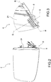
- the vehicle light in its most simple abstraction, comprises a container body, a lenticular body and at least one light source.
- the lenticular body is placed so as to close a mouth of the container body so as to form a housing chamber. Inside the housing chamber is arranged the light source, which can be directed so as to emit light towards the lenticular body, when electrically powered.
- the method of making a vehicle light once the various components are assembled, must provide for the fixing and sealing of the lenticular body on the container body.
- the lenticular bodies and the container bodies of vehicle lights are made of polymeric materials and comprise very complex geometries with curved or rectilinear coupling surfaces having inclinations that are also highly variable along the entire mutual coupling perimeter.
- a low wall or welding interface as a function of the geometry of the light to be welded, can have sudden changes of inclination with respect to the upper outer surface of the lenticular body, on which a laser beam is incident.
- the purpose of this invention is therefore to weld vehicle lights using a laser welding technique by overcoming the technical drawbacks linked to the specificity of vehicle lights that today make such a welding technique inconvenient and expensive.
- This purpose is achieved through a method of making a vehicle light according to claim 12 and by means of a vehicle light according to claim 1.
- reference number 4 indicates a vehicle light in its entirety, to which the discussion that follows will refer without, for this reason, losing generality.
- vehicle light means both a rear vehicle tail light or a front vehicle headlight, the latter also called projector, or headlamp.
- a vehicle light comprises at least one external light of the vehicle having a function of lighting and/or signalling, such as, for example, a position light, which can be a front, rear or side position light, a turn signal light, a brake light, a rear fog light, a low beam, a high beam and the like.
- a position light which can be a front, rear or side position light, a turn signal light, a brake light, a rear fog light, a low beam, a high beam and the like.
- the vehicle light 4 comprises a container body 8, usually made of polymeric material, which typically allows fixing the vehicle light 4 to the related vehicle.
- the container body 8 can have any shape and size, as well as positioning: for example, the container body may not be directly associated to the bodywork or to other hardware of the associable vehicle.
- the container body 8 delimits a containment seat 12 that houses at least one light source (not shown), electrically connected by to electrical connection means for powering it, and suitable to emit a light beam to be propagated outside of the vehicle light.
- the type of light source used is irrelevant; preferably, the light source 14 is a light emitting diode (LED) light source.
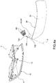
- the container body 8 is delimited by a first perimetral profile 20.
- a lenticular body 24 To the container body 8 is associated a lenticular body 24, in its turn delimited by a second perimetral profile 28.
- the lenticular body 24 is applied to the container body 8 so as to close said containment seat 12, which houses at least one light source.
- the lenticular body 24 can be outside the vehicle light 4, so as to define at least one outer wall of the vehicle light directly exposed to the atmosphere.
- the lenticular body 24 closes the containment seat 12 and is suitable to transmit towards the outside of the vehicle light 4 the light beam produced by the light source 14.
- the lenticular body 24 is made with material at least partially transparent, semi-transparent or translucent, also being able to include one or more opaque portions, so as, in any case, to allow the at least partial passage of the light beam produced by the light source.
- the material of the lenticular body 24 is a resin such as PMMA, PC and the like.
- the first and second perimetral profile 20,28 of the container body 8 and of the lenticular body 24 are at least partially counter-shaped to each other so as to interface, in an assembly configuration of the vehicle light 4, at a welding interface 32 of an abutment edge 36 of the lenticular body 24.
- the weld bead is formed at the welding interface 32 and there is the partial interpenetration of the abutment edge 36 and/or of the corresponding first perimetral profile 16.
- the assembly of the vehicle light 4 comprises the step of associating at least partially with each other the respective first and second perimetral profile 20,28.
- the method of making the vehicle light according to this invention provides for associating together the lenticular body and the container body, in correspondence of said perimetral profiles 20,28, by means of a laser weld.
- the laser welding process can be performed with different techniques, for example, with simultaneous laser welding, quasi-simultaneous welding, contour laser welding, mask laser welding, radial laser welding, globe laser welding, etc.
- At least one laser source is required, which emits a laser ray, light beam or electromagnetic radiation.
- the laser source comprises a CO2 laser, wherein the laser beam is produced by a gas mixture comprising CO2, or a YAG laser, wherein the laser beam is produced by a solid-state crystal, or a laser diode (LD).
- a CO2 laser wherein the laser beam is produced by a gas mixture comprising CO2, or a YAG laser, wherein the laser beam is produced by a solid-state crystal, or a laser diode (LD).
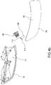
- the welding of the lenticular body 24 on the container body 8 is a laser type welding, wherein the light beam emitted by the laser source is directed towards the perimetral profiles 20,28 so as to reach the first perimetral profile 20 of the container body 8 after passing through the lenticular body 24.
- the container body 8 serves as an absorbent element in relation to the light beam emitted by the laser source and the lenticular body 24 serves as a transmissive element of the same light beam.
- the lenticular body 24 is a body made of polymeric material having transmittance values, in the emission spectrum of the laser source, greater than 90%.
- the lenticular body (24), at said abutment edge 36, comprises means of redirection 40 adapted to receive laser beams emitted by a laser source external to the light 4 and to the containment seat 12, to reflect them satisfying the condition of total internal reflection (TIR) and to direct them towards said welding interface 32.
- TIR total internal reflection
- the means of redirection 40 are facing the containment seat 12 so as not to be visible from the outside of the vehicle light 4; the laser beams are emitted by a source external to the vehicle light 4 so as to penetrate through the lenticular body 24 and reach the means of redirection 40 arranged internally in the vehicle light 4, namely its containment seat 12.
- Said laser beams impact an outer side wall 44 of the lenticular body 24, opposite the containment seat 12 and, after passing through the lenticular body 24, directly or by at least one reflection, impact said redirection means 40.
- the means of redirection 40 are, in turn, arranged on an inner face 48 of the abutment edge 36, said inner face 48 facing the containment seat 12 and being incident with the welding interface 32.
- the redirection means 40 are located in the inner side wall 56 of the lenticular body 24.
- the redirection means 40 are advantageously arranged on the inner side wall 56 of the lenticular body 24; said inner side wall 56 extends to the inner face 48 of the abutment edge 36, which is incident with the welding interface 32.
- the redirection means 40 can therefore be positioned generally on the inner side wall 56 of the lenticular body 24 and also on the inner face 48 of the abutment edge 36.
- Redirection means 40 means a portion of lenticular body 24 shaped so as to receive laser beams emitted by the external laser source, to reflect them satisfying the condition of total internal reflection (TIR) and to direct them towards said welding interface 32.
- TIR total internal reflection
- the means of redirection 40 extend perimetrally in a continuous manner, along the entire abutment edge 36 of the lenticular body 24, on the inner face 48 of said abutment edge 36.
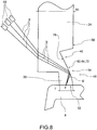
- said means of redirection 40 comprise a planar wall 52, having at least one rectilinear profile with respect to a cross-section plane S-S perpendicular to the welding interface 32 and perpendicular to a plane R-R tangent to an inner side wall 56 of the lenticular body 24, opposite said outer side wall 44.
- planar wall 52 is inclined so as to identify with the welding interface 32 an acute angle, on the side opposite the containment seat 12.
- the means of redirection 40 have a section defined by a polyline comprising a plurality of linear walls provided with rectilinear profiles, each straight profile identifying with the welding interface 32 an acute angle, on the side opposite the containment seat 12.
- the redirection means 40 comprise a curvilinear wall 60 having at least one hyperbolic profile 64, with respect to a cross-section plane S-S perpendicular to the welding interface 32 and perpendicular to a plane tangent to an inner side wall 56 of the lenticular body 24, opposite said outer side wall 44, in which a focus F of said hyperbolic profile 64 is positioned in the vicinity of said welding interface 32.
- the redirection means 40 comprise a curvilinear wall 60 having at least one parabolic profile 68, with respect to a cross-section plane S-S perpendicular to the welding interface 32 and perpendicular to a plane R-R tangent to an inner side wall 56 of the lenticular body 24, opposite said outer side wall 44, in which a focus F of said hyperbolic profile 68 is positioned in the vicinity of said welding interface 32.
- the redirection means 40 comprise a curvilinear wall 60 having at least one curvilinear profile 72, with respect to a cross-section plane S-S perpendicular to the welding interface 32 and perpendicular to a plane tangent to an inner side wall 56 of the lenticular body 24, opposite said outer side wall 44, said curvilinear profile 72 being shaped in such a way as to identify a hyperbolic profile 76 facing towards the incident laser rays, on the opposite side of the containment seat 12.
- the abutment edge 36 is positioned in a position recessed with respect to an outer side wall 44 of the lenticular body 24, i.e. on the side of the containment seat 12, in which the outer side wall 44 is opposite the inner side wall 56 of the lenticular body 24 that at least partly defines said containment seat 12.
- the abutment edge 36 has a width or thickness T reduced with respect to a thickness 80 of the lenticular body 24, in which the thickness 80 of the lenticular body 24 is given by the distance between the outer side wall 44 and the inner side wall 56. This distance is measured perpendicularly to the respective walls 44,56.
- the reduced thickness T of the abutment edge 36 facilitates the concentration of the laser beams and therefore concentrates the heat energy on the welding interface 32 in order to have an effective local melting of the same with the formation of a weld bead.
- the means of redirection 40 of the abutment edge 36 are obtained by means of a recess 84 formed on said inner side wall 56 of the lenticular body 24.
- a recess 84 formed on the inner side wall 56 of the lenticular body 24 is joined to the inner face 48 of the abutment edge 36 so as to create the planar 52 or curvilinear 60 wall of the redirection means 40.
- the method of making a vehicle light according to this invention comprises the steps of:
- the light beams emitted by the fibres are shown with the arrows B, so as to also schematically represent the reflections that these beams undergo inside the lenticular body 24 before impacting on the abutment edge 36 and on the welding interface 32.
- the means of redirection 40 are facing the containment seat 12 so as not to be visible from the outside of the vehicle light 4; the laser beams are emitted by a source external to the vehicle light 4 so as to penetrate through the lenticular body 24 and reach the means of redirection 40 arranged internally in the vehicle light 4, namely its containment seat 12.
- the step of directing the laser beams on the outer side wall 44 of the lenticular body 24 comprises the step of positioning the optical fibres 88 from a side of the outer side wall 44 of the lenticular body 24 so that the laser beams impact, directly or by at least one reflection, on the means of redirection 40 of the lenticular body 24 and, via the latter, impact the welding interface 32.
- the optical fibres 88 can be placed in an appropriate way in the space, also according to orientations different from each other, without physically interfering with each other, since the redirection means 40 of the lenticular body 24 allow suitably directing the rays coming from said optical fibres on the welding interface 32.
- Different orientations means that the optical fibres 88 can be parallel and/or skewed.
- the laser rays emitted can be either convergent, parallel or skewed with each other.
- the method of making a vehicle light comprises the step of providing at least one collimator device 92 between the optical fibres 88 and the lenticular body 24, so as to collimate along a predetermined optical axis X-X, the light beams coming from the optical fibres 88 and directing appropriately on the lenticular body 24 the light beams coming from the optical fibres 88, so that said light beams impact, directly or through at least one reflection, the means of redirection 40 facing the container body 8 on the side of the inner side wall 56 of the lenticular body 24.
- the collimator device 92 comprises a negative light guide 96, i.e. a light guide formed of reflective walls 100 inclined with respect to the optical axis X-X of the optical fibre 88, and in which the optical fibre 104 is positioned in the vicinity of an upper opening 104 of the negative light guide 96 and along the optical axis X-X.
- a negative light guide 96 i.e. a light guide formed of reflective walls 100 inclined with respect to the optical axis X-X of the optical fibre 88, and in which the optical fibre 104 is positioned in the vicinity of an upper opening 104 of the negative light guide 96 and along the optical axis X-X.
- the collimator device 92 comprises a positive light guide 108, i.e. a solid body suitable for satisfying the condition of total internal reflection for the at least one portion of incident laser beam, in which the solid body extends from an inlet 112 to an outlet 114, wherein the inlet 112 is facing said optical fibres 88 and the outlet 114 is facing said lenticular body 24, wherein the solid body is composed of a material transparent to the emission wavelength of the laser beam.
- a positive light guide 108 i.e. a solid body suitable for satisfying the condition of total internal reflection for the at least one portion of incident laser beam, in which the solid body extends from an inlet 112 to an outlet 114, wherein the inlet 112 is facing said optical fibres 88 and the outlet 114 is facing said lenticular body 24, wherein the solid body is composed of a material transparent to the emission wavelength of the laser beam.
- the laser welding techniques for the implementation method according to this invention can be of various types; for example, the laser welding step takes place by means of one or more optical fibres 88 that emit respective light radiations simultaneously to each other on different predetermined portions of said perimetral profiles 20,28, according to a "simultaneous" welding technique.
- this invention allows overcoming the drawbacks presented in the prior art.
- the light beam that strikes the interface is thus adequate to obtain a welding joint with excellent mechanical qualities, without wasting light power.
- the laser welding step performed with any technique, for example, "contour” or “simultaneous", is fast and reliable, allowing a further reduction of assembly costs with equal joint quality with respect to the known techniques.
- the light beam is at least partially absorbed by the lenticular body and therefore, in order to locally melt the container body (absorbent) in correspondence of the interface surface, it is necessary to send a high-power light beam. In this way, consumption would be increased, on the one hand, and there is a risk of unwanted melting or softening in different parts of the lenticular body, on the other.
- optical fibres can be positioned in space without physically interfering with each other.
Landscapes
- Physics & Mathematics (AREA)
- Engineering & Computer Science (AREA)
- Optics & Photonics (AREA)
- Mechanical Engineering (AREA)
- Electromagnetism (AREA)
- Health & Medical Sciences (AREA)
- Toxicology (AREA)
- General Engineering & Computer Science (AREA)
- Manufacturing & Machinery (AREA)
- Microelectronics & Electronic Packaging (AREA)
- Lining Or Joining Of Plastics Or The Like (AREA)
- Laser Beam Processing (AREA)
- Non-Portable Lighting Devices Or Systems Thereof (AREA)
- Lighting Device Outwards From Vehicle And Optical Signal (AREA)
Priority Applications (1)
| Application Number | Priority Date | Filing Date | Title |
|---|---|---|---|
| PL16172044T PL3115678T3 (pl) | 2015-06-01 | 2016-05-30 | Sposób wytwarzania lampy pojazdu i powiązana lampa pojazdu |
Applications Claiming Priority (1)
| Application Number | Priority Date | Filing Date | Title |
|---|---|---|---|
| ITUB2015A000956A ITUB20150956A1 (it) | 2015-06-01 | 2015-06-01 | Metodo di realizzazione di un fanale automobilistico e relativo fanale automobilistico |
Publications (2)
| Publication Number | Publication Date |
|---|---|
| EP3115678A1 EP3115678A1 (en) | 2017-01-11 |
| EP3115678B1 true EP3115678B1 (en) | 2020-12-02 |
Family
ID=54064448
Family Applications (1)
| Application Number | Title | Priority Date | Filing Date |
|---|---|---|---|
| EP16172044.6A Active EP3115678B1 (en) | 2015-06-01 | 2016-05-30 | Method of making a vehicle light and related vehicle light |
Country Status (6)
| Country | Link |
|---|---|
| US (1) | US10781990B2 (pl) |
| EP (1) | EP3115678B1 (pl) |
| CN (1) | CN106195694B (pl) |
| ES (1) | ES2857603T3 (pl) |
| IT (1) | ITUB20150956A1 (pl) |
| PL (1) | PL3115678T3 (pl) |
Families Citing this family (7)
| Publication number | Priority date | Publication date | Assignee | Title |
|---|---|---|---|---|
| FR3050795B1 (fr) * | 2016-04-27 | 2019-11-29 | Valeo Iluminacion | Dispositif lumineux comprenant au moins deux parties soudees au laser |
| IT201700041997A1 (it) * | 2017-04-14 | 2018-10-14 | Automotive Lighting Italia Spa | Attrezzatura di saldatura laser simultanea di un fanale automobilistico e metodo di saldatura laser simultanea di un fanale automobilistico |
| CN108050483A (zh) * | 2017-12-11 | 2018-05-18 | 上海小糸车灯有限公司 | Led照明灯具及汽车 |
| CN112074689B (zh) * | 2018-04-25 | 2022-08-19 | 株式会社小糸制作所 | 车辆用灯具 |
| JP7359076B2 (ja) * | 2020-04-30 | 2023-10-11 | 市光工業株式会社 | 車両用樹脂部品 |
| KR102884630B1 (ko) * | 2020-10-06 | 2025-11-10 | 현대자동차주식회사 | 자동차 그릴 |
| EP4006410B1 (en) * | 2020-11-25 | 2026-02-25 | Marelli Automotive Lighting Italy S.p.A. | Automotive lighting and/or signaling device and assembly method thereof |
Family Cites Families (24)
| Publication number | Priority date | Publication date | Assignee | Title |
|---|---|---|---|---|
| US5276303A (en) * | 1992-10-01 | 1994-01-04 | At&T Bell Laboratories | Laser bonding scheme |
| US6054072A (en) * | 1998-12-29 | 2000-04-25 | Ford Motor Company | Infrared bonding of transparent plastics articles |
| JP3973792B2 (ja) * | 1999-04-12 | 2007-09-12 | 株式会社小糸製作所 | 車両用灯具の製造方法 |
| JP3961737B2 (ja) * | 2000-02-29 | 2007-08-22 | 株式会社小糸製作所 | 車両用灯具およびその製造方法 |
| JP3913435B2 (ja) * | 2000-02-29 | 2007-05-09 | 株式会社小糸製作所 | 車両用灯具の製造方法 |
| JP3847517B2 (ja) * | 2000-03-30 | 2006-11-22 | スタンレー電気株式会社 | 光エネルギーによる樹脂製部品溶着方法 |
| JP4009432B2 (ja) * | 2001-03-29 | 2007-11-14 | トヨタ自動車株式会社 | 車両用灯具のレーザ溶着方法 |
| JP2004063332A (ja) * | 2002-07-30 | 2004-02-26 | Ichikoh Ind Ltd | 車両用灯具 |
| JP4318503B2 (ja) * | 2003-08-05 | 2009-08-26 | 株式会社小糸製作所 | 車両用灯具とその製造方法 |
| JP2005166359A (ja) * | 2003-12-01 | 2005-06-23 | Koito Mfg Co Ltd | 車両灯具用ランプボディおよび車両用灯具 |
| US20050121424A1 (en) * | 2003-12-05 | 2005-06-09 | Scott Caldwell | Optical horned lightpipe or lightguide |
| US7477828B2 (en) * | 2006-01-06 | 2009-01-13 | Lockheed Martin Corporation | Optical waveguide |
| AU2007207583A1 (en) * | 2006-01-17 | 2007-07-26 | Soliant Energy, Inc. | A hybrid primary optical component for optical concentrators |
| DE112007000978A5 (de) * | 2006-12-08 | 2009-04-09 | Mahle International Gmbh | Laserschweissverfahren |
| US20080260328A1 (en) * | 2007-04-20 | 2008-10-23 | 3M Innovative Properties Company | Led light extraction bar and injection optic for thin lightguide |
| KR20090064000A (ko) * | 2007-12-14 | 2009-06-18 | 현대자동차주식회사 | 차량용 램프유닛의 접합방법 |
| US8057081B2 (en) | 2009-02-11 | 2011-11-15 | GM Global Technology Operations LLC | Light guide for vehicle lamp assembly |
| EP2425458A4 (en) * | 2009-04-27 | 2017-03-15 | Sun Edge LLC | Non-imaging light concentrator |
| DE102009043200A1 (de) * | 2009-09-26 | 2011-04-21 | Continental Automotive Gmbh | Verfahren zum Verschweißen eines Kunststoffgehäuses |
| JP5497466B2 (ja) * | 2010-02-04 | 2014-05-21 | スタンレー電気株式会社 | 樹脂成形品の製造方法 |
| KR101797764B1 (ko) * | 2010-06-24 | 2017-11-15 | 스탠리 일렉트릭 컴퍼니, 리미티드 | 차량용 등 기구 및 차량용 등 기구 제조 방법 |
| JP5731184B2 (ja) * | 2010-12-15 | 2015-06-10 | 株式会社小糸製作所 | 車輌用灯具 |
| KR20140123134A (ko) * | 2013-04-10 | 2014-10-22 | 삼성전자주식회사 | 반사형 확산 렌즈 및 조명장치 |
| TR201904008T4 (tr) * | 2014-03-28 | 2019-04-22 | Automotive Lighting Italia S P A A Socio Unico | Bir otomobil lambasının lazer kaynağı yöntemi. |
-
2015
- 2015-06-01 IT ITUB2015A000956A patent/ITUB20150956A1/it unknown
-
2016
- 2016-05-30 PL PL16172044T patent/PL3115678T3/pl unknown
- 2016-05-30 EP EP16172044.6A patent/EP3115678B1/en active Active
- 2016-05-30 ES ES16172044T patent/ES2857603T3/es active Active
- 2016-05-31 US US15/168,573 patent/US10781990B2/en active Active
- 2016-06-01 CN CN201610383659.9A patent/CN106195694B/zh active Active
Non-Patent Citations (1)
| Title |
|---|
| SCHMAILZL ANTON ET AL: "Optimierung der Spanndruckverteilung beim Laserurhstrahlschweissen komplexer Bauteile mittels FE-Berechnung = Using FE calculation for the optimisation of the clamping pressure distribution in the case of the laser transmission welding of complex components", JOINING PLASTICS - FÜGEN VON KUNSTSTOFFEN, DVS, DEUTSCHER VERBAND FÜR SCHWEISSEN UND VERWANDTE VERFAHREN E.V, DÜSSELDORF, DE, vol. 7, no. 1, 1 January 2013 (2013-01-01), pages 30 - 34, XP001586475, ISSN: 1864-3450 * |
Also Published As
| Publication number | Publication date |
|---|---|
| PL3115678T3 (pl) | 2021-07-05 |
| US20160348866A1 (en) | 2016-12-01 |
| EP3115678A1 (en) | 2017-01-11 |
| ES2857603T3 (es) | 2021-09-29 |
| US10781990B2 (en) | 2020-09-22 |
| ITUB20150956A1 (it) | 2016-12-01 |
| CN106195694B (zh) | 2020-03-13 |
| CN106195694A (zh) | 2016-12-07 |
Similar Documents
| Publication | Publication Date | Title |
|---|---|---|
| EP3115678B1 (en) | Method of making a vehicle light and related vehicle light | |
| KR102379095B1 (ko) | 자동차 라이트의 레이저 용접 방법 및 이에 의해 제조된 자동차 라이트 | |
| EP2949452B1 (en) | Method of laser welding of an automotive light | |
| EP2957418B1 (en) | Apparatus for making an automotive headlight and method of simultaneous laser welding of an automotive headlight | |
| US9458986B2 (en) | Lighting unit | |
| EP3388736B1 (en) | Lens body and respective headlamp for vehicle | |
| KR20230038925A (ko) | 차량용 램프 및 그 램프를 포함하는 차량 | |
| EP2388512B1 (en) | Vehicle lightening unit | |
| KR101534703B1 (ko) | 자동차의 헤드 램프 | |
| US20220184739A1 (en) | Simultaneous Laser Welding Equipment of a Vehicle Light and Simultaneous Laser Welding Method of a Vehicle Light | |
| JP7079654B2 (ja) | 車両用灯具 | |
| JP4898557B2 (ja) | 車両用灯具 | |
| JP4574573B2 (ja) | 車両用灯具ユニット | |
| JP7283915B2 (ja) | 車輌用灯具 | |
| JP6009819B2 (ja) | 車両用灯具 | |
| KR102409841B1 (ko) | 차량용 램프 | |
| WO2021039234A1 (ja) | 車輌用灯具 | |
| JP2013033622A (ja) | 灯具 |
Legal Events
| Date | Code | Title | Description |
|---|---|---|---|
| PUAI | Public reference made under article 153(3) epc to a published international application that has entered the european phase |
Free format text: ORIGINAL CODE: 0009012 |
|
| STAA | Information on the status of an ep patent application or granted ep patent |
Free format text: STATUS: THE APPLICATION HAS BEEN PUBLISHED |
|
| AK | Designated contracting states |
Kind code of ref document: A1 Designated state(s): AL AT BE BG CH CY CZ DE DK EE ES FI FR GB GR HR HU IE IS IT LI LT LU LV MC MK MT NL NO PL PT RO RS SE SI SK SM TR |
|
| AX | Request for extension of the european patent |
Extension state: BA ME |
|
| STAA | Information on the status of an ep patent application or granted ep patent |
Free format text: STATUS: REQUEST FOR EXAMINATION WAS MADE |
|
| 17P | Request for examination filed |
Effective date: 20170706 |
|
| RBV | Designated contracting states (corrected) |
Designated state(s): AL AT BE BG CH CY CZ DE DK EE ES FI FR GB GR HR HU IE IS IT LI LT LU LV MC MK MT NL NO PL PT RO RS SE SI SK SM TR |
|
| REG | Reference to a national code |
Ref country code: DE Ref legal event code: R079 Ref document number: 602016048914 Country of ref document: DE Free format text: PREVIOUS MAIN CLASS: F21S0008100000 Ipc: B29C0065160000 |
|
| RIC1 | Information provided on ipc code assigned before grant |
Ipc: B29C 65/16 20060101AFI20200529BHEP Ipc: F21S 41/29 20180101ALI20200529BHEP Ipc: F21S 43/27 20180101ALI20200529BHEP |
|
| GRAP | Despatch of communication of intention to grant a patent |
Free format text: ORIGINAL CODE: EPIDOSNIGR1 |
|
| STAA | Information on the status of an ep patent application or granted ep patent |
Free format text: STATUS: GRANT OF PATENT IS INTENDED |
|
| INTG | Intention to grant announced |
Effective date: 20200710 |
|
| GRAS | Grant fee paid |
Free format text: ORIGINAL CODE: EPIDOSNIGR3 |
|
| GRAA | (expected) grant |
Free format text: ORIGINAL CODE: 0009210 |
|
| STAA | Information on the status of an ep patent application or granted ep patent |
Free format text: STATUS: THE PATENT HAS BEEN GRANTED |
|
| AK | Designated contracting states |
Kind code of ref document: B1 Designated state(s): AL AT BE BG CH CY CZ DE DK EE ES FI FR GB GR HR HU IE IS IT LI LT LU LV MC MK MT NL NO PL PT RO RS SE SI SK SM TR |
|
| RAP1 | Party data changed (applicant data changed or rights of an application transferred) |
Owner name: MARELLI AUTOMOTIVE LIGHTING ITALY S.P.A. |
|
| REG | Reference to a national code |
Ref country code: GB Ref legal event code: FG4D |
|
| REG | Reference to a national code |
Ref country code: AT Ref legal event code: REF Ref document number: 1340430 Country of ref document: AT Kind code of ref document: T Effective date: 20201215 Ref country code: CH Ref legal event code: EP |
|
| REG | Reference to a national code |
Ref country code: IE Ref legal event code: FG4D |
|
| REG | Reference to a national code |
Ref country code: DE Ref legal event code: R096 Ref document number: 602016048914 Country of ref document: DE |
|
| PG25 | Lapsed in a contracting state [announced via postgrant information from national office to epo] |
Ref country code: NO Free format text: LAPSE BECAUSE OF FAILURE TO SUBMIT A TRANSLATION OF THE DESCRIPTION OR TO PAY THE FEE WITHIN THE PRESCRIBED TIME-LIMIT Effective date: 20210302 Ref country code: RS Free format text: LAPSE BECAUSE OF FAILURE TO SUBMIT A TRANSLATION OF THE DESCRIPTION OR TO PAY THE FEE WITHIN THE PRESCRIBED TIME-LIMIT Effective date: 20201202 Ref country code: FI Free format text: LAPSE BECAUSE OF FAILURE TO SUBMIT A TRANSLATION OF THE DESCRIPTION OR TO PAY THE FEE WITHIN THE PRESCRIBED TIME-LIMIT Effective date: 20201202 Ref country code: GR Free format text: LAPSE BECAUSE OF FAILURE TO SUBMIT A TRANSLATION OF THE DESCRIPTION OR TO PAY THE FEE WITHIN THE PRESCRIBED TIME-LIMIT Effective date: 20210303 |
|
| REG | Reference to a national code |
Ref country code: NL Ref legal event code: MP Effective date: 20201202 |
|
| REG | Reference to a national code |
Ref country code: AT Ref legal event code: MK05 Ref document number: 1340430 Country of ref document: AT Kind code of ref document: T Effective date: 20201202 |
|
| PG25 | Lapsed in a contracting state [announced via postgrant information from national office to epo] |
Ref country code: BG Free format text: LAPSE BECAUSE OF FAILURE TO SUBMIT A TRANSLATION OF THE DESCRIPTION OR TO PAY THE FEE WITHIN THE PRESCRIBED TIME-LIMIT Effective date: 20210302 Ref country code: SE Free format text: LAPSE BECAUSE OF FAILURE TO SUBMIT A TRANSLATION OF THE DESCRIPTION OR TO PAY THE FEE WITHIN THE PRESCRIBED TIME-LIMIT Effective date: 20201202 Ref country code: LV Free format text: LAPSE BECAUSE OF FAILURE TO SUBMIT A TRANSLATION OF THE DESCRIPTION OR TO PAY THE FEE WITHIN THE PRESCRIBED TIME-LIMIT Effective date: 20201202 |
|
| PG25 | Lapsed in a contracting state [announced via postgrant information from national office to epo] |
Ref country code: NL Free format text: LAPSE BECAUSE OF FAILURE TO SUBMIT A TRANSLATION OF THE DESCRIPTION OR TO PAY THE FEE WITHIN THE PRESCRIBED TIME-LIMIT Effective date: 20201202 Ref country code: HR Free format text: LAPSE BECAUSE OF FAILURE TO SUBMIT A TRANSLATION OF THE DESCRIPTION OR TO PAY THE FEE WITHIN THE PRESCRIBED TIME-LIMIT Effective date: 20201202 |
|
| REG | Reference to a national code |
Ref country code: LT Ref legal event code: MG9D |
|
| PG25 | Lapsed in a contracting state [announced via postgrant information from national office to epo] |
Ref country code: SM Free format text: LAPSE BECAUSE OF FAILURE TO SUBMIT A TRANSLATION OF THE DESCRIPTION OR TO PAY THE FEE WITHIN THE PRESCRIBED TIME-LIMIT Effective date: 20201202 Ref country code: RO Free format text: LAPSE BECAUSE OF FAILURE TO SUBMIT A TRANSLATION OF THE DESCRIPTION OR TO PAY THE FEE WITHIN THE PRESCRIBED TIME-LIMIT Effective date: 20201202 Ref country code: SK Free format text: LAPSE BECAUSE OF FAILURE TO SUBMIT A TRANSLATION OF THE DESCRIPTION OR TO PAY THE FEE WITHIN THE PRESCRIBED TIME-LIMIT Effective date: 20201202 Ref country code: PT Free format text: LAPSE BECAUSE OF FAILURE TO SUBMIT A TRANSLATION OF THE DESCRIPTION OR TO PAY THE FEE WITHIN THE PRESCRIBED TIME-LIMIT Effective date: 20210405 Ref country code: LT Free format text: LAPSE BECAUSE OF FAILURE TO SUBMIT A TRANSLATION OF THE DESCRIPTION OR TO PAY THE FEE WITHIN THE PRESCRIBED TIME-LIMIT Effective date: 20201202 Ref country code: EE Free format text: LAPSE BECAUSE OF FAILURE TO SUBMIT A TRANSLATION OF THE DESCRIPTION OR TO PAY THE FEE WITHIN THE PRESCRIBED TIME-LIMIT Effective date: 20201202 |
|
| PG25 | Lapsed in a contracting state [announced via postgrant information from national office to epo] |
Ref country code: AT Free format text: LAPSE BECAUSE OF FAILURE TO SUBMIT A TRANSLATION OF THE DESCRIPTION OR TO PAY THE FEE WITHIN THE PRESCRIBED TIME-LIMIT Effective date: 20201202 |
|
| REG | Reference to a national code |
Ref country code: DE Ref legal event code: R097 Ref document number: 602016048914 Country of ref document: DE |
|
| REG | Reference to a national code |
Ref country code: ES Ref legal event code: FG2A Ref document number: 2857603 Country of ref document: ES Kind code of ref document: T3 Effective date: 20210929 |
|
| PG25 | Lapsed in a contracting state [announced via postgrant information from national office to epo] |
Ref country code: IS Free format text: LAPSE BECAUSE OF FAILURE TO SUBMIT A TRANSLATION OF THE DESCRIPTION OR TO PAY THE FEE WITHIN THE PRESCRIBED TIME-LIMIT Effective date: 20210402 |
|
| PLBE | No opposition filed within time limit |
Free format text: ORIGINAL CODE: 0009261 |
|
| STAA | Information on the status of an ep patent application or granted ep patent |
Free format text: STATUS: NO OPPOSITION FILED WITHIN TIME LIMIT |
|
| PG25 | Lapsed in a contracting state [announced via postgrant information from national office to epo] |
Ref country code: AL Free format text: LAPSE BECAUSE OF FAILURE TO SUBMIT A TRANSLATION OF THE DESCRIPTION OR TO PAY THE FEE WITHIN THE PRESCRIBED TIME-LIMIT Effective date: 20201202 |
|
| 26N | No opposition filed |
Effective date: 20210903 |
|
| PG25 | Lapsed in a contracting state [announced via postgrant information from national office to epo] |
Ref country code: SI Free format text: LAPSE BECAUSE OF FAILURE TO SUBMIT A TRANSLATION OF THE DESCRIPTION OR TO PAY THE FEE WITHIN THE PRESCRIBED TIME-LIMIT Effective date: 20201202 Ref country code: DK Free format text: LAPSE BECAUSE OF FAILURE TO SUBMIT A TRANSLATION OF THE DESCRIPTION OR TO PAY THE FEE WITHIN THE PRESCRIBED TIME-LIMIT Effective date: 20201202 |
|
| REG | Reference to a national code |
Ref country code: CH Ref legal event code: PL |
|
| PG25 | Lapsed in a contracting state [announced via postgrant information from national office to epo] |
Ref country code: CH Free format text: LAPSE BECAUSE OF NON-PAYMENT OF DUE FEES Effective date: 20210531 Ref country code: LI Free format text: LAPSE BECAUSE OF NON-PAYMENT OF DUE FEES Effective date: 20210531 Ref country code: MC Free format text: LAPSE BECAUSE OF FAILURE TO SUBMIT A TRANSLATION OF THE DESCRIPTION OR TO PAY THE FEE WITHIN THE PRESCRIBED TIME-LIMIT Effective date: 20201202 Ref country code: LU Free format text: LAPSE BECAUSE OF NON-PAYMENT OF DUE FEES Effective date: 20210530 |
|
| REG | Reference to a national code |
Ref country code: BE Ref legal event code: MM Effective date: 20210531 |
|
| PG25 | Lapsed in a contracting state [announced via postgrant information from national office to epo] |
Ref country code: IE Free format text: LAPSE BECAUSE OF NON-PAYMENT OF DUE FEES Effective date: 20210530 |
|
| PG25 | Lapsed in a contracting state [announced via postgrant information from national office to epo] |
Ref country code: IS Free format text: LAPSE BECAUSE OF FAILURE TO SUBMIT A TRANSLATION OF THE DESCRIPTION OR TO PAY THE FEE WITHIN THE PRESCRIBED TIME-LIMIT Effective date: 20210402 |
|
| PG25 | Lapsed in a contracting state [announced via postgrant information from national office to epo] |
Ref country code: BE Free format text: LAPSE BECAUSE OF NON-PAYMENT OF DUE FEES Effective date: 20210531 |
|
| PG25 | Lapsed in a contracting state [announced via postgrant information from national office to epo] |
Ref country code: HU Free format text: LAPSE BECAUSE OF FAILURE TO SUBMIT A TRANSLATION OF THE DESCRIPTION OR TO PAY THE FEE WITHIN THE PRESCRIBED TIME-LIMIT; INVALID AB INITIO Effective date: 20160530 |
|
| PG25 | Lapsed in a contracting state [announced via postgrant information from national office to epo] |
Ref country code: CY Free format text: LAPSE BECAUSE OF FAILURE TO SUBMIT A TRANSLATION OF THE DESCRIPTION OR TO PAY THE FEE WITHIN THE PRESCRIBED TIME-LIMIT Effective date: 20201202 |
|
| P01 | Opt-out of the competence of the unified patent court (upc) registered |
Effective date: 20230526 |
|
| PG25 | Lapsed in a contracting state [announced via postgrant information from national office to epo] |
Ref country code: MK Free format text: LAPSE BECAUSE OF FAILURE TO SUBMIT A TRANSLATION OF THE DESCRIPTION OR TO PAY THE FEE WITHIN THE PRESCRIBED TIME-LIMIT Effective date: 20201202 |
|
| PGFP | Annual fee paid to national office [announced via postgrant information from national office to epo] |
Ref country code: GB Payment date: 20240419 Year of fee payment: 9 |
|
| PGFP | Annual fee paid to national office [announced via postgrant information from national office to epo] |
Ref country code: ES Payment date: 20240603 Year of fee payment: 9 |
|
| PGFP | Annual fee paid to national office [announced via postgrant information from national office to epo] |
Ref country code: CZ Payment date: 20240423 Year of fee payment: 9 |
|
| PGFP | Annual fee paid to national office [announced via postgrant information from national office to epo] |
Ref country code: PL Payment date: 20240423 Year of fee payment: 9 |
|
| PGFP | Annual fee paid to national office [announced via postgrant information from national office to epo] |
Ref country code: TR Payment date: 20240502 Year of fee payment: 9 |
|
| PG25 | Lapsed in a contracting state [announced via postgrant information from national office to epo] |
Ref country code: MT Free format text: LAPSE BECAUSE OF FAILURE TO SUBMIT A TRANSLATION OF THE DESCRIPTION OR TO PAY THE FEE WITHIN THE PRESCRIBED TIME-LIMIT Effective date: 20201202 |
|
| PGFP | Annual fee paid to national office [announced via postgrant information from national office to epo] |
Ref country code: DE Payment date: 20250423 Year of fee payment: 10 |
|
| PGFP | Annual fee paid to national office [announced via postgrant information from national office to epo] |
Ref country code: IT Payment date: 20250423 Year of fee payment: 10 |
|
| PGFP | Annual fee paid to national office [announced via postgrant information from national office to epo] |
Ref country code: FR Payment date: 20250423 Year of fee payment: 10 |
|
| PG25 | Lapsed in a contracting state [announced via postgrant information from national office to epo] |
Ref country code: CZ Free format text: LAPSE BECAUSE OF NON-PAYMENT OF DUE FEES Effective date: 20250530 |
|
| GBPC | Gb: european patent ceased through non-payment of renewal fee |
Effective date: 20250530 |
|
| PG25 | Lapsed in a contracting state [announced via postgrant information from national office to epo] |
Ref country code: GB Free format text: LAPSE BECAUSE OF NON-PAYMENT OF DUE FEES Effective date: 20250530 |