EP3115237A1 - Offene dachkonstruktion für ein fahrzeug und rolloanordnung zur verwendung darin - Google Patents
Offene dachkonstruktion für ein fahrzeug und rolloanordnung zur verwendung darin Download PDFInfo
- Publication number
- EP3115237A1 EP3115237A1 EP15175892.7A EP15175892A EP3115237A1 EP 3115237 A1 EP3115237 A1 EP 3115237A1 EP 15175892 A EP15175892 A EP 15175892A EP 3115237 A1 EP3115237 A1 EP 3115237A1
- Authority
- EP
- European Patent Office
- Prior art keywords
- holding groove
- rollo screen
- rollo
- hooking member
- roof construction
- Prior art date
- Legal status (The legal status is an assumption and is not a legal conclusion. Google has not performed a legal analysis and makes no representation as to the accuracy of the status listed.)
- Granted
Links
- 238000010276 construction Methods 0.000 title claims abstract description 33
- 238000004804 winding Methods 0.000 claims abstract description 24
- 230000000475 sunscreen effect Effects 0.000 description 9
- 239000000516 sunscreening agent Substances 0.000 description 9
- 239000004033 plastic Substances 0.000 description 6
- 229920003023 plastic Polymers 0.000 description 6
- 239000000463 material Substances 0.000 description 3
- 239000006260 foam Substances 0.000 description 2
- 230000003068 static effect Effects 0.000 description 2
- 230000006835 compression Effects 0.000 description 1
- 238000007906 compression Methods 0.000 description 1
- 238000006073 displacement reaction Methods 0.000 description 1
- 238000001125 extrusion Methods 0.000 description 1
- 229920003229 poly(methyl methacrylate) Polymers 0.000 description 1
- 239000004926 polymethyl methacrylate Substances 0.000 description 1
- 230000008092 positive effect Effects 0.000 description 1
Images


Classifications
-
- B—PERFORMING OPERATIONS; TRANSPORTING
- B60—VEHICLES IN GENERAL
- B60J—WINDOWS, WINDSCREENS, NON-FIXED ROOFS, DOORS, OR SIMILAR DEVICES FOR VEHICLES; REMOVABLE EXTERNAL PROTECTIVE COVERINGS SPECIALLY ADAPTED FOR VEHICLES
- B60J7/00—Non-fixed roofs; Roofs with movable panels, e.g. rotary sunroofs
- B60J7/02—Non-fixed roofs; Roofs with movable panels, e.g. rotary sunroofs of sliding type, e.g. comprising guide shoes
- B60J7/06—Non-fixed roofs; Roofs with movable panels, e.g. rotary sunroofs of sliding type, e.g. comprising guide shoes with non-rigid element or elements
- B60J7/067—Non-fixed roofs; Roofs with movable panels, e.g. rotary sunroofs of sliding type, e.g. comprising guide shoes with non-rigid element or elements sliding and winding up
-
- B—PERFORMING OPERATIONS; TRANSPORTING
- B60—VEHICLES IN GENERAL
- B60J—WINDOWS, WINDSCREENS, NON-FIXED ROOFS, DOORS, OR SIMILAR DEVICES FOR VEHICLES; REMOVABLE EXTERNAL PROTECTIVE COVERINGS SPECIALLY ADAPTED FOR VEHICLES
- B60J7/00—Non-fixed roofs; Roofs with movable panels, e.g. rotary sunroofs
- B60J7/0007—Non-fixed roofs; Roofs with movable panels, e.g. rotary sunroofs moveable head-liners, screens, curtains or blinds for ceilings
- B60J7/0015—Non-fixed roofs; Roofs with movable panels, e.g. rotary sunroofs moveable head-liners, screens, curtains or blinds for ceilings roller blind
-
- E—FIXED CONSTRUCTIONS
- E06—DOORS, WINDOWS, SHUTTERS, OR ROLLER BLINDS IN GENERAL; LADDERS
- E06B—FIXED OR MOVABLE CLOSURES FOR OPENINGS IN BUILDINGS, VEHICLES, FENCES OR LIKE ENCLOSURES IN GENERAL, e.g. DOORS, WINDOWS, BLINDS, GATES
- E06B9/00—Screening or protective devices for wall or similar openings, with or without operating or securing mechanisms; Closures of similar construction
- E06B9/56—Operating, guiding or securing devices or arrangements for roll-type closures; Spring drums; Tape drums; Counterweighting arrangements therefor
- E06B9/58—Guiding devices
- E06B9/581—Means to prevent or induce disengagement of shutter from side rails
Definitions
- the invention firstly relates to an open roof construction for a vehicle according to the preamble of claim 1.
- Such an open roof construction is described in copending European patent application 15154788.2 . It describes an open roof construction having a sunscreen comprising a visible portion and a non-visible portion above it.
- the visible portion is stationary with respect to the sides of the roof opening and the non-visible portion can be unwound at one end and reversed into the visible portion on the opposite end.
- the visible portion is stationary, but the length of it varies to open and close the rollo screen. Because of such a stationary position of the rollo screen edge of the visible portion, any connections there also have a stationary position to the stationary part of the open roof construction. This has a positive effect on the life span and reliability of these connections, while allowing to simplify the design of these connections.
- the open roof construction comprises the features of the characterizing portion of claim 1.
- the edges of the sunscreen are reliably held on the one hand and are easily inserted into and removed from the holding groove on the other hand.
- the winding shaft for the rollo screen is rotatable around a stationary axis of rotation, and wherein the rollo screen, starting from the winding shaft, firstly extends in a first direction D1, next around a reversal member at the position of the operating beam and finally back in an opposite second direction D2 and ends at the rollo screen edge which is attached to a stationary member of the open roof construction.
- This embodiment has the advantage that the winding shaft, which is relatively bulky, is stationary, so it is not necessary to reserve room for it along the whole length of the sunscreen.
- Each hooking member may be resiliently compressible so as to be insertable into the holding groove through the narrow entrance and expandable once within the holding groove, the operating beam being provided with a compression element compressing the hooking member when the rollo screen is wound on to enable the hooking member to leave the holding groove.
- the hooking member can change its shape with the assistance of the displacing element to enable entering and exiting the holding groove.
- the operating beam is provided with a pushing member to push the hooking member into the holding groove when the operating beam is moved to unwind the rollo screen.
- the hooking member will change its shape as a result of the pushing member pushing the compressible and expandable hooking member through the narrow entrance of the holding groove.
- the pushing member may comprise a knife-shaped element which extends into the holding groove. Due to the knife shape, it will fit through the narrow entrance of the holding groove and thus the pushing action can be continued into the holding groove to further improve the reliability of the pushing-in action.
- the knife-shaped element is circular and rotatable, the sliding movements between the knife-shaped element and the hooking member will be minimized to minimize the wear of the hooking member.
- the hooking member includes a sharp inward corner facing the narrow entrance opening, the knife-shaped element engaging the corner when it pushes the hooking member into the holding groove.
- the sharp inward corner provides a reliable position for the pushing member to exert pushing forces.
- the pushing member remains outside the holding groove and the hooking member will then be made rigidly enough to be pushed from outside the holding groove.
- the narrow opening of the holding groove is on the upper side thereof.
- the narrow opening of the holding groove is on the lateral side thereof facing the opposite holding groove.
- the hooking member is arrow shaped.
- the arrow shaped member may then hook on both sides of the holding groove (with a fitting arrangement of the holding groove).
- the hooking member is formed of a rigid strip folded away from the edge of the rollo screen.
- the operating beam may be provided with a locking member arranged within the holding groove on the side of the rollo screen facing away from the rigid strip in order to push the rollo screen and the rigid strip toward a side of the holding groove such that the rigid strip is hooking behind a rib defining one side of the narrow entrance.
- the locking member keeps the rigid strip of the hooking member in engagement with the rib, thus improving the reliability of the hooking action.
- the locking member may be a translucent rod-shaped member which is visible through the narrow entrance of the holding groove and which is lighted by a light source, which is either stationary lighting the rod-shaped member from the side, or is movable with the rod-shaped member and lighting it from the end.
- the locking member may thus have more than one function. It can even have a further function if it replaces a drive cable for the sunscreen engaging the operating beam.
- the rod-shaped member forming the locking member will generally have to be bendable if space requires so and in case it moves with the operating beam and should extend along the whole (visible portion of the) sunscreen when it is unwound.
- the rod-shaped member may be stationary and compressible or movable in a direction perpendicular to length of the rod-shaped member to allow the displacing element to pass.
- the invention further relates to a rollo assembly intended for use in an open roof construction according to the present invention.
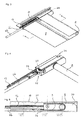
- an open roof construction for a vehicle comprises a roof opening 1 in a stationary roof part 2 which can be closed by a movable roof closure.
- a front roof opening 1a and a rear roof opening 1b closable by a rigid transparent front panel 3a and a rigid transparent rear panel 3b.
- roof panel or panels 3 may be operated (by means not illustrated but generally known) for opening and closing the roof opening 1.
- One of the panels 3, normally the rear panel 3b, may also be fixed.
- a rollo assembly 4 here acting as a sunscreen assembly, is positioned below said roof opening 1 (although it is noted that parts of such a rollo assembly 4 also may be located below the stationary roof part 2).
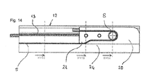
- the rollo assembly 4 comprises a rollo screen 5 and a winding shaft 6 for the rollo screen 5 which is rotatable around a stationary axis of rotation 7.
- the rollo screen 5, starting from the winding shaft 6, firstly extends substantially in a first direction D1, next around a reversal member 8 and finally back in an opposite second direction D2 and ends at a rollo screen edge 9 which is attached to a stationary member 10 of the open roof construction.
- the reversal member 8 is movable in parallel to said first and second directions D1, D2 in correspondence with the amount of rollo screen 5 being wound on or off said winding shaft 6.
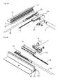
- the reversal member 8 has two opposite longitudinal edges 11 ( Fig. 2 ) guided in two opposite guides 12 extending in parallel to said first and second directions D1,D2 (generally the lengthwise direction of the vehicle) at opposite side edges of the roof opening 1.
- Two drive cables 13 (which are part of a drive mechanism) are provided engaging said opposite ends 11 of the reversal member 8.
- the drive cables 13 may run in cable channels (not illustrated here) provided in the guides 12. The position of the reversal member 8 and thus of the rollo screen 5 is controlled by the drive cables 13.
- the reversal member 8 (and thus the rollo screen 5) has been illustrated in two different positions: in solid lines a position 8' in which the rollo screen 5 is in a position substantially fully opening the roof opening 1 (see also Fig. 2a ) and at least partially hidden by a headlining 14 and with dashed lines a fully closed position 8 (see also Fig. 2b ).
- the lower, visible portion of the rollo screen 5 is stationary, only the length thereof varies due to the movement of the reversal member.
- the winding shaft 6 is provided with a spring member (such as an internal coiled spring) biasing the winding shaft 6 in a direction for winding the rollo screen 5.
- a spring member such as an internal coiled spring biasing the winding shaft 6 in a direction for winding the rollo screen 5.
- the reversal member 8 comprises a rotatable cylindrical member which will rotate in accordance with the rollo screen 5 moving around it when the reversal member 8 is displaced.
- the reversal member may comprise a non-rotating member providing or defining a low friction surface intended for engaging the rollo screen 5.
- the reversal member 8 further may be provided with a cover member 15 which hides the part of the rollo screen 5 extending around the reversal member 8 from view.
- the guides 12 are used for supporting the rollo screen 5 and keeping it in a desired position.
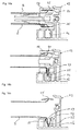
- Figs. 3 - 7 show the cooperation between one of the guides 12 and the sunscreen 5 in one embodiment.
- the guide 12 comprises a holding groove 16 having a narrow entrance opening 17 formed by a lower and upper rib 18, 19 (see in particular Fig. 7 ).
- the entrance opening 17 is directed horizontally towards the opposed holding groove 16 of the other guide 12.
- the reversal member 8 and the cover member 15 (not shown here) form the operating beam for the sunscreen 5.
- the slider 20 is guided by one or more guide grooves 21 in the guide 12.
- Rollo screen displacing means 22 are attached to the slider 20.
- the hooking member 25 is formed by a rigid strip folded away from the edge of the rollo screen 5. Such strip is known per se. In the embodiment shown, the strip of the hooking member 25 is folded in upward direction.
- the adjacent edge 11 of the rollo screen 5 may also be formed from more rigid, for example plastic, material, so that the hooking member 25 includes a sharp inward corner 25a in which the knife-shaped element 23 may engage.
- the hooking member 25 is resiliently compressible so as to enter the holding groove 16 through the narrow opening 17 and expandable once in the holding groove 16.
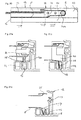
- Fig. 6b and the cross-sections of Figs. 7a - 7c show that the knife-shaped element 23 has a varying extent in lateral direction when seen in longitudinally different cross-sections.
- the lateral extent is such that it remains outside the holding groove 16.
- the knife-shaped element 23 gradually extends into the holding groove 16, such that when the knife-shaped element moves along the edge 11 of the rollo screen 5, the strip 25 and the adjacent edge 11 of the rollo screen 5 are stretched outwardly into the holding groove 16.
- Fig. 7b it has completely entered the holding groove 16, but it is inside the compressing element 24, so that it cannot expand.
- the locking rod 26 moves with the reversal member 8. If it is at least partly transparent, this locking rod 26 may also function as light emitting rod, emitting light through the narrow entrance opening 17 of the holding groove 16 to the interior of the vehicle.
- a light source 27 e.g. a LED
- Fig. 8a shows that the light source 27 is attached to the slider 20 or displacing means 22. The light is then transmitted through the slider 20 and/or displacing means 22 to the light emitting locking rod 26.
- the light source may also be arranged on the other end of the locking rod 26.
- the light source 27 may be switched on and off, for example switched on if the rollo screen 5 is fully closed or fully opened. In the embodiment where the light source is movable, the switch could be on the light source 27 itself. If necessary, measures should be taken to distribute the light along the length of the locking rod 26, especially if the light source 27 is arranged alongside the locking rod.
- the locking rod 26 is stationary in longitudinal direction. In order to allow the compressing element 24 to pass the locking rod 26, it is made of a compressible material, such as static foam. In Fig. 9a the locking rod 26 is in its locking position keeping the hooking member 25 in a high position within the holding groove 16. In Fig. 9b , the locking rod 26 is locally compressed downwardly by the compressing element 24, so that it may move with respect to the locking rod 26 without requiring additional cross sectional space in the holding groove 16.
- the locking rod 26 itself is not compressible, but an additional element 28, for example made of static foam or another spring member, is in this case provided in a lateral extension 16' of the holding groove 16 and is compressible to allow the locking rod 26 to enter the lateral extension 16' when the compressing element 24 has to pass the locking rod 26.
- an additional element 28 for example made of static foam or another spring member, is in this case provided in a lateral extension 16' of the holding groove 16 and is compressible to allow the locking rod 26 to enter the lateral extension 16' when the compressing element 24 has to pass the locking rod 26.
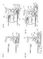
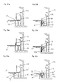
- Figs. 11a - 11d show different configurations of the hooking member 25 and holding groove 16.
- Fig. 11a shows an arrangement similar to that in the embodiment of Figs 4-7 (although the height of the holding groove is so small that no locking rod is provided.
- Fig. 11b shows a variation in which the hooking member 25 is arrow-shaped, i.e. it has two hooks or rigid strips, one on each side of the rollo screen 5. Each strip engages the respective rib 18 or 19 bordering the narrow entrance opening 17 of the holding groove 16.
- the narrow entrance opening 17 of the holding groove 16 is on the upper side thereof, so that the hooking member 25, here with a single strip, must now be inserted into and removed from the holding groove 25 in a vertical direction.
- the holding groove 16 having the narrow entrance opening 17 on the upper side is combined with the arrow shaped hooking member 25.
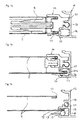
- Figs. 12 - 16 show an embodiment of the rollo assembly having the hooking member and holding groove arrangement of Fig. 11d .
- Figs. 12 -16 show that slider 20 comprises a guide 29 for the hooking member 25 where it is flattened in vertical direction and points in upward direction. When it is reversed at the reversal member 8 it will point downward ( Fig. 16a ) and is then ready to be introduced into the holding groove 16 when it is flattened in horizontal direction in order to pass the narrow entrance opening 17 ( Fig. 16b ). A knife-shaped element 23 is again provided to push the hooking member 25 into the holding groove 16 past the narrow entrance opening 17 ( Fig. 16c ). A compressing element 24 is also present (see Fig. 16b ), operating in the same manner is in the former embodiment.
- the rollo screen 5 adjacent the hooking member 25 is angled approximately 90 degrees into the holding groove 16.
- the arrow shaped hooking member 25 will hook behind both ribs 18, 19 defining the narrow opening 17. In combination with the angled pulling force from the rollo screen 5, a very reliable hooking within the holding groove 16 is accomplished.
- Figs. 17 - 19 show the variation of the rollo assembly 4 with a rotating knife-shaped element 23 to push the hooking member 25 into the holding groove 16.
- the outlet of the guide groove 29 in the slider 20 is adjacent to the entrance 17 of the holding groove 16.
- the compressing element 24 guides the hooking member 25 towards the rotating knife-shape element 23.
- Figs. 20, 21 show an embodiment in which a pushing member 30 of the rollo screen displacement means 22 remains outside the holding groove 16.
- the compressing element 24 has a portion 24a outside the holding groove 16.
- the hooking member 25 is guided by it and the pushing member 30 pushes the hooking member 25 from the outside portion 24a to the inside portion 24b of the compressing element 24.
- the edge 11 of the rollo screen 5 adjacent the hooking member 25 and the hooking member 25 itself are made from hard plastic so that it is possible to exert a pushing force onto it.
- Figs. 22 -24 show some further examples of manners to introduce the hooking member 25 into the holding groove by means of the knife-shaped element 23.
- Fig. 22a it is shown that the hooking member 25 and adjacent rollo screen edge 11 are substantially aligned when outside the holding groove 16.
- the knife-shaped element 23 pushes downwardly at the position where the strip of the hooking member 25 starts, i.e. where the strip will be angled down to form the hooking member 25 according to Fig. 22b .
- the strip of the hooking member 25 is provided with a relatively rigid flap 25b pointing upwards in the position of Fig. 23a , and forming a reference point for the knife-shaped element 23.
- the knife-shaped element 23 will push in the inward angle between the strip and the flap of the hooking member 25 which will reduce wear to the rollo screen, also if the knife-shaped element 23 and the hooking member 25 slide with respect to each other, as the knife-shaped element is in contact with relative rigid and sturdy plastic material only.
- Fig. 24a shows a further variation in which the hooking member 25 is arrow-shaped, such that there is an inward short arrow arm 25' and an outward longer arrow arm 25''.
- the height of the holding groove at the position of the ribs 18 and 19 is adapted to the length of the arrow arms 25' and 25''.
- the difference in length is chosen as a result of the fact that the outward arrow arm 25'' will easier and earlier be introduced into the holding groove 16 than the inward arm 25'.
- Figs. 25a,b show two positions of an embodiment of the arrow-shaped hooking member 25 before and after it is introduced into the holding groove 16.
- the hooking member 25 is formed by the edge 11 of the rollo screen 5 and an additional plastic strip 25b, both covered by a plastic layer 31 to attach the plastic strip and to make the edge of the rollo screen more rigid.
- the arrow is folded flat and points upwards, while in Fig. 25b , it points downwards.
- Fig. 26 comprises a one piece arrow-shaped hooking member 25 which is attached to a shortened edge 11 of the rollo screen.
- the body of the arrow includes a living hinge 32 to allow the rigid body to be bent into a 90 degree angle ( Fig. 26b ).
- Fig. 27 shows an embodiment in which the arrow includes a flexible center piece 33 attached at right angles to the edge 11 of the rollo screen.
- the rigid arms 25', 25'' of the arrow are attached to opposite ends of the center piece, and can be folded by means of the flexible center piece between the straight ( Fig. 27a ) and pointed position ( Fig. 27b ).
- the arrow-shaped hooking member 25 may for example be formed by 2K extrusion to obtain portions (33, 25', 25'') of the hooking member 25 having different characteristics.
- Fig. 28 shows a last embodiment in which the arms of the arrow are each formed by a loose pre-curved strip 34 attached, here by means of a stitch 35, to the edge 11 of the rollo screen 5.
- the resilient strips 34 can be deformed so as to be more straight and able to enter the holding groove 16 through the narrow entrance 17 and then return to the original shape to act as a hooking member 25.
- the invention is not limited to the embodiments described before, which may be varied widely within the scope of the invention as defined by the appending claims.
- the winding shaft is then arranged at the position of the reversal member, so that the winding shaft moves when the rollo screen is wound or unwound.
- the translucent rod-shaped member with the light source could have a wider range of use.
- Such movable or stationary rod-shaped member could be combined with any kind of rollo system or even any kind of open roof construction, as long as there is a guide having a groove in which the translucent rod shaped member can be accommodated and which has one or more openings, preferably elongated as the narrow opening in the holding groove, through which the light from the rod-shaped member could be transmitted to the interior of the vehicle, particularly towards the lower side of the rollo screen.
- the rod-shaped member could move with a drive member, such as the drive cable or a part of a mechanism coupled to it. It could also be stationary. It could be provided in its own groove or in a common groove, for example together with the hooking member or drive cable.
- the light source could be arranged at the end of the rod-shaped member or along the length thereof.
- the rod-shaped member could be made of PMMA and could be bendable, which is especially convenient if it is movable so that it can have its own run-out tube which is curved and bent inwardly.
Landscapes
- Engineering & Computer Science (AREA)
- Mechanical Engineering (AREA)
- Structural Engineering (AREA)
- Architecture (AREA)
- Civil Engineering (AREA)
- Operating, Guiding And Securing Of Roll- Type Closing Members (AREA)
Priority Applications (4)
| Application Number | Priority Date | Filing Date | Title |
|---|---|---|---|
| EP15175892.7A EP3115237B1 (de) | 2015-07-08 | 2015-07-08 | Offene dachkonstruktion für ein fahrzeug und rolloanordnung zur verwendung darin |
| US15/202,380 US20170008383A1 (en) | 2015-07-08 | 2016-07-05 | Open roof construction for a vehicle and rollo assembly for use therein |
| CN201610537061.0A CN106335352B (zh) | 2015-07-08 | 2016-07-08 | 用于车辆的开放式顶板结构以及在其中使用的卷帘组件 |
| US15/640,054 US10173503B2 (en) | 2015-07-08 | 2017-06-30 | Open roof construction for a vehicle and rollo assembly for use therein |
Applications Claiming Priority (1)
| Application Number | Priority Date | Filing Date | Title |
|---|---|---|---|
| EP15175892.7A EP3115237B1 (de) | 2015-07-08 | 2015-07-08 | Offene dachkonstruktion für ein fahrzeug und rolloanordnung zur verwendung darin |
Publications (2)
| Publication Number | Publication Date |
|---|---|
| EP3115237A1 true EP3115237A1 (de) | 2017-01-11 |
| EP3115237B1 EP3115237B1 (de) | 2020-03-04 |
Family
ID=53539572
Family Applications (1)
| Application Number | Title | Priority Date | Filing Date |
|---|---|---|---|
| EP15175892.7A Active EP3115237B1 (de) | 2015-07-08 | 2015-07-08 | Offene dachkonstruktion für ein fahrzeug und rolloanordnung zur verwendung darin |
Country Status (3)
| Country | Link |
|---|---|
| US (1) | US20170008383A1 (de) |
| EP (1) | EP3115237B1 (de) |
| CN (1) | CN106335352B (de) |
Cited By (2)
| Publication number | Priority date | Publication date | Assignee | Title |
|---|---|---|---|---|
| CN107599795A (zh) * | 2017-09-07 | 2018-01-19 | 芜湖皖江知识产权运营中心有限公司 | 电动汽车 |
| EP3275708A1 (de) * | 2016-07-28 | 2018-01-31 | Inalfa Roof Systems Group B.V. | Offene dachkonstruktion für ein fahrzeug und rolloanordnung zur verwendung darin |
Families Citing this family (10)
| Publication number | Priority date | Publication date | Assignee | Title |
|---|---|---|---|---|
| EP3017985B1 (de) * | 2014-11-06 | 2021-01-27 | Inalfa Roof Systems Group B.V. | Sonnenschutzvorrichtung und dazugehöriger flexibler Sonnenschutz |
| DE102015005167A1 (de) * | 2015-04-23 | 2016-10-27 | Webasto SE | Fahrzeugdachmodul mit einem Dachelement und einer Rolloeinrichtung |
| JP6517646B2 (ja) * | 2015-09-24 | 2019-05-22 | アイシン精機株式会社 | シェード装置 |
| US11248416B2 (en) * | 2016-01-13 | 2022-02-15 | Cornellcookson, Llc | Roll-up doors and method for securing same |
| JP6891608B2 (ja) | 2017-04-06 | 2021-06-18 | 株式会社アイシン | サンシェード装置 |
| CN109789755B (zh) * | 2018-03-27 | 2022-06-10 | 曾尧宗 | 一种含移动伸缩遮阳板的汽车 |
| US10737561B2 (en) * | 2018-05-30 | 2020-08-11 | Nissan North America, Inc. | Sunroof structure |
| US10843539B2 (en) | 2019-03-20 | 2020-11-24 | AISIN Technical Center of America, Inc. | Tensioner apparatus for use with vehicle sunroofs |
| DE102019131964A1 (de) * | 2019-11-26 | 2021-05-27 | Webasto SE | Anordnung und Verfahren zum Herstellen einer Anordnung für eine Verdunkelungsvorrichtung für ein Fahrzeugdach und Fahrzeugdach für ein Kraftfahrzeug |
| EP3888960B1 (de) * | 2020-03-30 | 2023-06-21 | Inalfa Roof Systems Group B.V. | Sonnenblendenanordnung |
Citations (4)
| Publication number | Priority date | Publication date | Assignee | Title |
|---|---|---|---|---|
| EP1553259A1 (de) * | 2004-01-12 | 2005-07-13 | Inalfa Roof Systems Group B.V. | Sonnenschutz |
| EP1712389A1 (de) * | 2005-04-14 | 2006-10-18 | Inalfa Roof Systems Group B.V. | Vorrichtung zur Abdeckung einer Öffnung |
| WO2010022768A1 (en) * | 2008-08-27 | 2010-03-04 | Inalfa Roof Systems Group B.V. | Sunshade assembly and open roof construction provided therewith |
| DE102009033885A1 (de) * | 2009-07-20 | 2011-01-27 | Macauto Industrial Co., Ltd., Yung-Kang | Fahrzeugdach-Rolloanordnung |
Family Cites Families (5)
| Publication number | Priority date | Publication date | Assignee | Title |
|---|---|---|---|---|
| CN2834995Y (zh) * | 2005-08-26 | 2006-11-08 | 史航 | 皮卡车厢的软厢盖装置 |
| US7798568B2 (en) * | 2008-08-06 | 2010-09-21 | Inalfa Roof Systems Group B.V. | Sunshade assembly and open roof construction provided therewith |
| US7967052B2 (en) * | 2009-01-08 | 2011-06-28 | Macauto Industrial Co., Ltd. | Vehicle roof blind assembly |
| US8419119B2 (en) * | 2010-10-26 | 2013-04-16 | Yachiyo Industry Co., Ltd. | Sunshade device |
| EP2730441B1 (de) * | 2012-11-12 | 2017-06-28 | Inalfa Roof Systems Group B.V. | Rolloanordnung und damit ausgestattete offene Dachkonstruktion |
-
2015
- 2015-07-08 EP EP15175892.7A patent/EP3115237B1/de active Active
-
2016
- 2016-07-05 US US15/202,380 patent/US20170008383A1/en not_active Abandoned
- 2016-07-08 CN CN201610537061.0A patent/CN106335352B/zh active Active
Patent Citations (4)
| Publication number | Priority date | Publication date | Assignee | Title |
|---|---|---|---|---|
| EP1553259A1 (de) * | 2004-01-12 | 2005-07-13 | Inalfa Roof Systems Group B.V. | Sonnenschutz |
| EP1712389A1 (de) * | 2005-04-14 | 2006-10-18 | Inalfa Roof Systems Group B.V. | Vorrichtung zur Abdeckung einer Öffnung |
| WO2010022768A1 (en) * | 2008-08-27 | 2010-03-04 | Inalfa Roof Systems Group B.V. | Sunshade assembly and open roof construction provided therewith |
| DE102009033885A1 (de) * | 2009-07-20 | 2011-01-27 | Macauto Industrial Co., Ltd., Yung-Kang | Fahrzeugdach-Rolloanordnung |
Cited By (2)
| Publication number | Priority date | Publication date | Assignee | Title |
|---|---|---|---|---|
| EP3275708A1 (de) * | 2016-07-28 | 2018-01-31 | Inalfa Roof Systems Group B.V. | Offene dachkonstruktion für ein fahrzeug und rolloanordnung zur verwendung darin |
| CN107599795A (zh) * | 2017-09-07 | 2018-01-19 | 芜湖皖江知识产权运营中心有限公司 | 电动汽车 |
Also Published As
| Publication number | Publication date |
|---|---|
| CN106335352B (zh) | 2020-10-27 |
| EP3115237B1 (de) | 2020-03-04 |
| CN106335352A (zh) | 2017-01-18 |
| US20170008383A1 (en) | 2017-01-12 |
Similar Documents
| Publication | Publication Date | Title |
|---|---|---|
| EP3115237B1 (de) | Offene dachkonstruktion für ein fahrzeug und rolloanordnung zur verwendung darin | |
| US10173503B2 (en) | Open roof construction for a vehicle and rollo assembly for use therein | |
| US11370282B2 (en) | Guide and sunshade assembly provided therewith | |
| JP4617289B2 (ja) | 後部窓を完全に日除けするウィンドウシェード | |
| JP3163685U (ja) | ブラインドシステム | |
| EP0999335A1 (de) | Abschirmeinrichtung | |
| KR101605841B1 (ko) | 롤러 블라인드 잠금장치를 구비한 차양 롤러 블라인드 | |
| JPH04345522A (ja) | 遮蔽装置 | |
| US4564234A (en) | Cover for mirror for sun visor, particularly for automobiles | |
| US20120291964A1 (en) | Blind assembly with two blind head rail | |
| KR20090023262A (ko) | 헤드 레일 조립체 | |
| EP2487317A1 (de) | Sichtblendenvorrichtung | |
| CN106183743B (zh) | 卷帘组件和设有卷帘组件的用于车辆的敞口车顶结构 | |
| EP2902260A2 (de) | Öffnungsfähiges Dach für ein Fahrzeug und dazugehörige Rolloanordnung | |
| EP3463951B1 (de) | Offene dachkonstruktion für ein fahrzeug und rolloanordnung zur verwendung darin | |
| CN108979497B (zh) | 具有底部轨条调平机构的用于建筑特征的遮盖物 | |
| JP6976819B2 (ja) | 電動サンシェードとサンルーフの構造 | |
| JP6018772B2 (ja) | 日除けアセンブリおよび日除けアセンブリが設けられたオープンルーフ構造 | |
| JP6514962B2 (ja) | 巻取式スクリーン装置 | |
| EP3275708B1 (de) | Offene dachkonstruktion für ein fahrzeug und rolloanordnung zur verwendung darin | |
| WO2012137716A1 (ja) | シェード装置 | |
| KR101855862B1 (ko) | 롤러 블라인드에 패브릭 샤프트 회전 모듈과 패브릭 블레이드 이동 모듈을 포함하는 선 루프 | |
| EP3613619B1 (de) | Führungsschiene zur verwendung in einer offenen dachkonstruktion und offene dachkonstruktion mit solch einer führungsschiene | |
| KR101473225B1 (ko) | 수직 이동형 블라인드 | |
| CN111546862B (zh) | 一种敞开式车顶组件 |
Legal Events
| Date | Code | Title | Description |
|---|---|---|---|
| PUAI | Public reference made under article 153(3) epc to a published international application that has entered the european phase |
Free format text: ORIGINAL CODE: 0009012 |
|
| STAA | Information on the status of an ep patent application or granted ep patent |
Free format text: STATUS: THE APPLICATION HAS BEEN PUBLISHED |
|
| AK | Designated contracting states |
Kind code of ref document: A1 Designated state(s): AL AT BE BG CH CY CZ DE DK EE ES FI FR GB GR HR HU IE IS IT LI LT LU LV MC MK MT NL NO PL PT RO RS SE SI SK SM TR |
|
| AX | Request for extension of the european patent |
Extension state: BA ME |
|
| STAA | Information on the status of an ep patent application or granted ep patent |
Free format text: STATUS: REQUEST FOR EXAMINATION WAS MADE |
|
| 17P | Request for examination filed |
Effective date: 20170629 |
|
| RBV | Designated contracting states (corrected) |
Designated state(s): AL AT BE BG CH CY CZ DE DK EE ES FI FR GB GR HR HU IE IS IT LI LT LU LV MC MK MT NL NO PL PT RO RS SE SI SK SM TR |
|
| GRAP | Despatch of communication of intention to grant a patent |
Free format text: ORIGINAL CODE: EPIDOSNIGR1 |
|
| STAA | Information on the status of an ep patent application or granted ep patent |
Free format text: STATUS: GRANT OF PATENT IS INTENDED |
|
| INTG | Intention to grant announced |
Effective date: 20191122 |
|
| GRAS | Grant fee paid |
Free format text: ORIGINAL CODE: EPIDOSNIGR3 |
|
| GRAA | (expected) grant |
Free format text: ORIGINAL CODE: 0009210 |
|
| STAA | Information on the status of an ep patent application or granted ep patent |
Free format text: STATUS: THE PATENT HAS BEEN GRANTED |
|
| AK | Designated contracting states |
Kind code of ref document: B1 Designated state(s): AL AT BE BG CH CY CZ DE DK EE ES FI FR GB GR HR HU IE IS IT LI LT LU LV MC MK MT NL NO PL PT RO RS SE SI SK SM TR |
|
| REG | Reference to a national code |
Ref country code: GB Ref legal event code: FG4D |
|
| REG | Reference to a national code |
Ref country code: CH Ref legal event code: EP |
|
| REG | Reference to a national code |
Ref country code: AT Ref legal event code: REF Ref document number: 1239966 Country of ref document: AT Kind code of ref document: T Effective date: 20200315 |
|
| REG | Reference to a national code |
Ref country code: DE Ref legal event code: R096 Ref document number: 602015048037 Country of ref document: DE |
|
| REG | Reference to a national code |
Ref country code: IE Ref legal event code: FG4D |
|
| PG25 | Lapsed in a contracting state [announced via postgrant information from national office to epo] |
Ref country code: FI Free format text: LAPSE BECAUSE OF FAILURE TO SUBMIT A TRANSLATION OF THE DESCRIPTION OR TO PAY THE FEE WITHIN THE PRESCRIBED TIME-LIMIT Effective date: 20200304 Ref country code: RS Free format text: LAPSE BECAUSE OF FAILURE TO SUBMIT A TRANSLATION OF THE DESCRIPTION OR TO PAY THE FEE WITHIN THE PRESCRIBED TIME-LIMIT Effective date: 20200304 Ref country code: NO Free format text: LAPSE BECAUSE OF FAILURE TO SUBMIT A TRANSLATION OF THE DESCRIPTION OR TO PAY THE FEE WITHIN THE PRESCRIBED TIME-LIMIT Effective date: 20200604 |
|
| REG | Reference to a national code |
Ref country code: NL Ref legal event code: MP Effective date: 20200304 |
|
| PG25 | Lapsed in a contracting state [announced via postgrant information from national office to epo] |
Ref country code: GR Free format text: LAPSE BECAUSE OF FAILURE TO SUBMIT A TRANSLATION OF THE DESCRIPTION OR TO PAY THE FEE WITHIN THE PRESCRIBED TIME-LIMIT Effective date: 20200605 Ref country code: BG Free format text: LAPSE BECAUSE OF FAILURE TO SUBMIT A TRANSLATION OF THE DESCRIPTION OR TO PAY THE FEE WITHIN THE PRESCRIBED TIME-LIMIT Effective date: 20200604 Ref country code: HR Free format text: LAPSE BECAUSE OF FAILURE TO SUBMIT A TRANSLATION OF THE DESCRIPTION OR TO PAY THE FEE WITHIN THE PRESCRIBED TIME-LIMIT Effective date: 20200304 Ref country code: SE Free format text: LAPSE BECAUSE OF FAILURE TO SUBMIT A TRANSLATION OF THE DESCRIPTION OR TO PAY THE FEE WITHIN THE PRESCRIBED TIME-LIMIT Effective date: 20200304 Ref country code: LV Free format text: LAPSE BECAUSE OF FAILURE TO SUBMIT A TRANSLATION OF THE DESCRIPTION OR TO PAY THE FEE WITHIN THE PRESCRIBED TIME-LIMIT Effective date: 20200304 |
|
| REG | Reference to a national code |
Ref country code: LT Ref legal event code: MG4D |
|
| PG25 | Lapsed in a contracting state [announced via postgrant information from national office to epo] |
Ref country code: NL Free format text: LAPSE BECAUSE OF FAILURE TO SUBMIT A TRANSLATION OF THE DESCRIPTION OR TO PAY THE FEE WITHIN THE PRESCRIBED TIME-LIMIT Effective date: 20200304 |
|
| PG25 | Lapsed in a contracting state [announced via postgrant information from national office to epo] |
Ref country code: PT Free format text: LAPSE BECAUSE OF FAILURE TO SUBMIT A TRANSLATION OF THE DESCRIPTION OR TO PAY THE FEE WITHIN THE PRESCRIBED TIME-LIMIT Effective date: 20200729 Ref country code: ES Free format text: LAPSE BECAUSE OF FAILURE TO SUBMIT A TRANSLATION OF THE DESCRIPTION OR TO PAY THE FEE WITHIN THE PRESCRIBED TIME-LIMIT Effective date: 20200304 Ref country code: CZ Free format text: LAPSE BECAUSE OF FAILURE TO SUBMIT A TRANSLATION OF THE DESCRIPTION OR TO PAY THE FEE WITHIN THE PRESCRIBED TIME-LIMIT Effective date: 20200304 Ref country code: IS Free format text: LAPSE BECAUSE OF FAILURE TO SUBMIT A TRANSLATION OF THE DESCRIPTION OR TO PAY THE FEE WITHIN THE PRESCRIBED TIME-LIMIT Effective date: 20200704 Ref country code: SM Free format text: LAPSE BECAUSE OF FAILURE TO SUBMIT A TRANSLATION OF THE DESCRIPTION OR TO PAY THE FEE WITHIN THE PRESCRIBED TIME-LIMIT Effective date: 20200304 Ref country code: EE Free format text: LAPSE BECAUSE OF FAILURE TO SUBMIT A TRANSLATION OF THE DESCRIPTION OR TO PAY THE FEE WITHIN THE PRESCRIBED TIME-LIMIT Effective date: 20200304 Ref country code: LT Free format text: LAPSE BECAUSE OF FAILURE TO SUBMIT A TRANSLATION OF THE DESCRIPTION OR TO PAY THE FEE WITHIN THE PRESCRIBED TIME-LIMIT Effective date: 20200304 Ref country code: SK Free format text: LAPSE BECAUSE OF FAILURE TO SUBMIT A TRANSLATION OF THE DESCRIPTION OR TO PAY THE FEE WITHIN THE PRESCRIBED TIME-LIMIT Effective date: 20200304 Ref country code: RO Free format text: LAPSE BECAUSE OF FAILURE TO SUBMIT A TRANSLATION OF THE DESCRIPTION OR TO PAY THE FEE WITHIN THE PRESCRIBED TIME-LIMIT Effective date: 20200304 |
|
| REG | Reference to a national code |
Ref country code: AT Ref legal event code: MK05 Ref document number: 1239966 Country of ref document: AT Kind code of ref document: T Effective date: 20200304 |
|
| REG | Reference to a national code |
Ref country code: DE Ref legal event code: R097 Ref document number: 602015048037 Country of ref document: DE |
|
| PLBE | No opposition filed within time limit |
Free format text: ORIGINAL CODE: 0009261 |
|
| STAA | Information on the status of an ep patent application or granted ep patent |
Free format text: STATUS: NO OPPOSITION FILED WITHIN TIME LIMIT |
|
| PG25 | Lapsed in a contracting state [announced via postgrant information from national office to epo] |
Ref country code: IT Free format text: LAPSE BECAUSE OF FAILURE TO SUBMIT A TRANSLATION OF THE DESCRIPTION OR TO PAY THE FEE WITHIN THE PRESCRIBED TIME-LIMIT Effective date: 20200304 Ref country code: DK Free format text: LAPSE BECAUSE OF FAILURE TO SUBMIT A TRANSLATION OF THE DESCRIPTION OR TO PAY THE FEE WITHIN THE PRESCRIBED TIME-LIMIT Effective date: 20200304 Ref country code: AT Free format text: LAPSE BECAUSE OF FAILURE TO SUBMIT A TRANSLATION OF THE DESCRIPTION OR TO PAY THE FEE WITHIN THE PRESCRIBED TIME-LIMIT Effective date: 20200304 |
|
| 26N | No opposition filed |
Effective date: 20201207 |
|
| PG25 | Lapsed in a contracting state [announced via postgrant information from national office to epo] |
Ref country code: PL Free format text: LAPSE BECAUSE OF FAILURE TO SUBMIT A TRANSLATION OF THE DESCRIPTION OR TO PAY THE FEE WITHIN THE PRESCRIBED TIME-LIMIT Effective date: 20200304 Ref country code: MC Free format text: LAPSE BECAUSE OF FAILURE TO SUBMIT A TRANSLATION OF THE DESCRIPTION OR TO PAY THE FEE WITHIN THE PRESCRIBED TIME-LIMIT Effective date: 20200304 Ref country code: SI Free format text: LAPSE BECAUSE OF FAILURE TO SUBMIT A TRANSLATION OF THE DESCRIPTION OR TO PAY THE FEE WITHIN THE PRESCRIBED TIME-LIMIT Effective date: 20200304 |
|
| REG | Reference to a national code |
Ref country code: CH Ref legal event code: PL |
|
| GBPC | Gb: european patent ceased through non-payment of renewal fee |
Effective date: 20200708 |
|
| REG | Reference to a national code |
Ref country code: BE Ref legal event code: MM Effective date: 20200731 |
|
| PG25 | Lapsed in a contracting state [announced via postgrant information from national office to epo] |
Ref country code: GB Free format text: LAPSE BECAUSE OF NON-PAYMENT OF DUE FEES Effective date: 20200708 Ref country code: CH Free format text: LAPSE BECAUSE OF NON-PAYMENT OF DUE FEES Effective date: 20200731 Ref country code: LU Free format text: LAPSE BECAUSE OF NON-PAYMENT OF DUE FEES Effective date: 20200708 Ref country code: LI Free format text: LAPSE BECAUSE OF NON-PAYMENT OF DUE FEES Effective date: 20200731 |
|
| PG25 | Lapsed in a contracting state [announced via postgrant information from national office to epo] |
Ref country code: BE Free format text: LAPSE BECAUSE OF NON-PAYMENT OF DUE FEES Effective date: 20200731 |
|
| PG25 | Lapsed in a contracting state [announced via postgrant information from national office to epo] |
Ref country code: IE Free format text: LAPSE BECAUSE OF NON-PAYMENT OF DUE FEES Effective date: 20200708 |
|
| PG25 | Lapsed in a contracting state [announced via postgrant information from national office to epo] |
Ref country code: TR Free format text: LAPSE BECAUSE OF FAILURE TO SUBMIT A TRANSLATION OF THE DESCRIPTION OR TO PAY THE FEE WITHIN THE PRESCRIBED TIME-LIMIT Effective date: 20200304 Ref country code: MT Free format text: LAPSE BECAUSE OF FAILURE TO SUBMIT A TRANSLATION OF THE DESCRIPTION OR TO PAY THE FEE WITHIN THE PRESCRIBED TIME-LIMIT Effective date: 20200304 Ref country code: CY Free format text: LAPSE BECAUSE OF FAILURE TO SUBMIT A TRANSLATION OF THE DESCRIPTION OR TO PAY THE FEE WITHIN THE PRESCRIBED TIME-LIMIT Effective date: 20200304 |
|
| PG25 | Lapsed in a contracting state [announced via postgrant information from national office to epo] |
Ref country code: MK Free format text: LAPSE BECAUSE OF FAILURE TO SUBMIT A TRANSLATION OF THE DESCRIPTION OR TO PAY THE FEE WITHIN THE PRESCRIBED TIME-LIMIT Effective date: 20200304 Ref country code: AL Free format text: LAPSE BECAUSE OF FAILURE TO SUBMIT A TRANSLATION OF THE DESCRIPTION OR TO PAY THE FEE WITHIN THE PRESCRIBED TIME-LIMIT Effective date: 20200304 |
|
| PGFP | Annual fee paid to national office [announced via postgrant information from national office to epo] |
Ref country code: FR Payment date: 20220725 Year of fee payment: 8 |
|
| PGFP | Annual fee paid to national office [announced via postgrant information from national office to epo] |
Ref country code: DE Payment date: 20230727 Year of fee payment: 9 |
|
| PG25 | Lapsed in a contracting state [announced via postgrant information from national office to epo] |
Ref country code: FR Free format text: LAPSE BECAUSE OF NON-PAYMENT OF DUE FEES Effective date: 20230731 |