EP3113728B1 - Implantable medical device constraint and deployment apparatus - Google Patents
Implantable medical device constraint and deployment apparatus Download PDFInfo
- Publication number
- EP3113728B1 EP3113728B1 EP15711374.7A EP15711374A EP3113728B1 EP 3113728 B1 EP3113728 B1 EP 3113728B1 EP 15711374 A EP15711374 A EP 15711374A EP 3113728 B1 EP3113728 B1 EP 3113728B1
- Authority
- EP
- European Patent Office
- Prior art keywords
- sheath
- deployment
- implantable device
- deployment system
- constraining member
- Prior art date
- Legal status (The legal status is an assumption and is not a legal conclusion. Google has not performed a legal analysis and makes no representation as to the accuracy of the status listed.)
- Active
Links
Images


Classifications
-
- A—HUMAN NECESSITIES
- A61—MEDICAL OR VETERINARY SCIENCE; HYGIENE
- A61F—FILTERS IMPLANTABLE INTO BLOOD VESSELS; PROSTHESES; DEVICES PROVIDING PATENCY TO, OR PREVENTING COLLAPSING OF, TUBULAR STRUCTURES OF THE BODY, e.g. STENTS; ORTHOPAEDIC, NURSING OR CONTRACEPTIVE DEVICES; FOMENTATION; TREATMENT OR PROTECTION OF EYES OR EARS; BANDAGES, DRESSINGS OR ABSORBENT PADS; FIRST-AID KITS
- A61F2/00—Filters implantable into blood vessels; Prostheses, i.e. artificial substitutes or replacements for parts of the body; Appliances for connecting them with the body; Devices providing patency to, or preventing collapsing of, tubular structures of the body, e.g. stents
- A61F2/95—Instruments specially adapted for placement or removal of stents or stent-grafts
- A61F2/9517—Instruments specially adapted for placement or removal of stents or stent-grafts handle assemblies therefor
-
- A—HUMAN NECESSITIES
- A61—MEDICAL OR VETERINARY SCIENCE; HYGIENE
- A61F—FILTERS IMPLANTABLE INTO BLOOD VESSELS; PROSTHESES; DEVICES PROVIDING PATENCY TO, OR PREVENTING COLLAPSING OF, TUBULAR STRUCTURES OF THE BODY, e.g. STENTS; ORTHOPAEDIC, NURSING OR CONTRACEPTIVE DEVICES; FOMENTATION; TREATMENT OR PROTECTION OF EYES OR EARS; BANDAGES, DRESSINGS OR ABSORBENT PADS; FIRST-AID KITS
- A61F2/00—Filters implantable into blood vessels; Prostheses, i.e. artificial substitutes or replacements for parts of the body; Appliances for connecting them with the body; Devices providing patency to, or preventing collapsing of, tubular structures of the body, e.g. stents
- A61F2/82—Devices providing patency to, or preventing collapsing of, tubular structures of the body, e.g. stents
- A61F2/856—Single tubular stent with a side portal passage
-
- A—HUMAN NECESSITIES
- A61—MEDICAL OR VETERINARY SCIENCE; HYGIENE
- A61F—FILTERS IMPLANTABLE INTO BLOOD VESSELS; PROSTHESES; DEVICES PROVIDING PATENCY TO, OR PREVENTING COLLAPSING OF, TUBULAR STRUCTURES OF THE BODY, e.g. STENTS; ORTHOPAEDIC, NURSING OR CONTRACEPTIVE DEVICES; FOMENTATION; TREATMENT OR PROTECTION OF EYES OR EARS; BANDAGES, DRESSINGS OR ABSORBENT PADS; FIRST-AID KITS
- A61F2/00—Filters implantable into blood vessels; Prostheses, i.e. artificial substitutes or replacements for parts of the body; Appliances for connecting them with the body; Devices providing patency to, or preventing collapsing of, tubular structures of the body, e.g. stents
- A61F2/95—Instruments specially adapted for placement or removal of stents or stent-grafts
- A61F2/962—Instruments specially adapted for placement or removal of stents or stent-grafts having an outer sleeve
- A61F2/966—Instruments specially adapted for placement or removal of stents or stent-grafts having an outer sleeve with relative longitudinal movement between outer sleeve and prosthesis, e.g. using a push rod
-
- A—HUMAN NECESSITIES
- A61—MEDICAL OR VETERINARY SCIENCE; HYGIENE
- A61B—DIAGNOSIS; SURGERY; IDENTIFICATION
- A61B17/00—Surgical instruments, devices or methods
- A61B17/0057—Implements for plugging an opening in the wall of a hollow or tubular organ, e.g. for sealing a vessel puncture or closing a cardiac septal defect
-
- A—HUMAN NECESSITIES
- A61—MEDICAL OR VETERINARY SCIENCE; HYGIENE
- A61B—DIAGNOSIS; SURGERY; IDENTIFICATION
- A61B17/00—Surgical instruments, devices or methods
- A61B17/12—Surgical instruments, devices or methods for ligaturing or otherwise compressing tubular parts of the body, e.g. blood vessels or umbilical cord
- A61B17/12022—Occluding by internal devices, e.g. balloons or releasable wires
- A61B17/12099—Occluding by internal devices, e.g. balloons or releasable wires characterised by the location of the occluder
- A61B17/12109—Occluding by internal devices, e.g. balloons or releasable wires characterised by the location of the occluder in a blood vessel
-
- A—HUMAN NECESSITIES
- A61—MEDICAL OR VETERINARY SCIENCE; HYGIENE
- A61B—DIAGNOSIS; SURGERY; IDENTIFICATION
- A61B17/00—Surgical instruments, devices or methods
- A61B17/12—Surgical instruments, devices or methods for ligaturing or otherwise compressing tubular parts of the body, e.g. blood vessels or umbilical cord
- A61B17/12022—Occluding by internal devices, e.g. balloons or releasable wires
- A61B17/12099—Occluding by internal devices, e.g. balloons or releasable wires characterised by the location of the occluder
- A61B17/12122—Occluding by internal devices, e.g. balloons or releasable wires characterised by the location of the occluder within the heart
-
- A—HUMAN NECESSITIES
- A61—MEDICAL OR VETERINARY SCIENCE; HYGIENE
- A61F—FILTERS IMPLANTABLE INTO BLOOD VESSELS; PROSTHESES; DEVICES PROVIDING PATENCY TO, OR PREVENTING COLLAPSING OF, TUBULAR STRUCTURES OF THE BODY, e.g. STENTS; ORTHOPAEDIC, NURSING OR CONTRACEPTIVE DEVICES; FOMENTATION; TREATMENT OR PROTECTION OF EYES OR EARS; BANDAGES, DRESSINGS OR ABSORBENT PADS; FIRST-AID KITS
- A61F2/00—Filters implantable into blood vessels; Prostheses, i.e. artificial substitutes or replacements for parts of the body; Appliances for connecting them with the body; Devices providing patency to, or preventing collapsing of, tubular structures of the body, e.g. stents
- A61F2/01—Filters implantable into blood vessels
- A61F2/011—Instruments for their placement or removal
-
- A—HUMAN NECESSITIES
- A61—MEDICAL OR VETERINARY SCIENCE; HYGIENE
- A61F—FILTERS IMPLANTABLE INTO BLOOD VESSELS; PROSTHESES; DEVICES PROVIDING PATENCY TO, OR PREVENTING COLLAPSING OF, TUBULAR STRUCTURES OF THE BODY, e.g. STENTS; ORTHOPAEDIC, NURSING OR CONTRACEPTIVE DEVICES; FOMENTATION; TREATMENT OR PROTECTION OF EYES OR EARS; BANDAGES, DRESSINGS OR ABSORBENT PADS; FIRST-AID KITS
- A61F2/00—Filters implantable into blood vessels; Prostheses, i.e. artificial substitutes or replacements for parts of the body; Appliances for connecting them with the body; Devices providing patency to, or preventing collapsing of, tubular structures of the body, e.g. stents
- A61F2/02—Prostheses implantable into the body
- A61F2/04—Hollow or tubular parts of organs, e.g. bladders, tracheae, bronchi or bile ducts
- A61F2/06—Blood vessels
- A61F2/07—Stent-grafts
-
- A—HUMAN NECESSITIES
- A61—MEDICAL OR VETERINARY SCIENCE; HYGIENE
- A61F—FILTERS IMPLANTABLE INTO BLOOD VESSELS; PROSTHESES; DEVICES PROVIDING PATENCY TO, OR PREVENTING COLLAPSING OF, TUBULAR STRUCTURES OF THE BODY, e.g. STENTS; ORTHOPAEDIC, NURSING OR CONTRACEPTIVE DEVICES; FOMENTATION; TREATMENT OR PROTECTION OF EYES OR EARS; BANDAGES, DRESSINGS OR ABSORBENT PADS; FIRST-AID KITS
- A61F2/00—Filters implantable into blood vessels; Prostheses, i.e. artificial substitutes or replacements for parts of the body; Appliances for connecting them with the body; Devices providing patency to, or preventing collapsing of, tubular structures of the body, e.g. stents
- A61F2/82—Devices providing patency to, or preventing collapsing of, tubular structures of the body, e.g. stents
- A61F2/86—Stents in a form characterised by the wire-like elements; Stents in the form characterised by a net-like or mesh-like structure
- A61F2/90—Stents in a form characterised by the wire-like elements; Stents in the form characterised by a net-like or mesh-like structure characterised by a net-like or mesh-like structure
-
- A—HUMAN NECESSITIES
- A61—MEDICAL OR VETERINARY SCIENCE; HYGIENE
- A61F—FILTERS IMPLANTABLE INTO BLOOD VESSELS; PROSTHESES; DEVICES PROVIDING PATENCY TO, OR PREVENTING COLLAPSING OF, TUBULAR STRUCTURES OF THE BODY, e.g. STENTS; ORTHOPAEDIC, NURSING OR CONTRACEPTIVE DEVICES; FOMENTATION; TREATMENT OR PROTECTION OF EYES OR EARS; BANDAGES, DRESSINGS OR ABSORBENT PADS; FIRST-AID KITS
- A61F2/00—Filters implantable into blood vessels; Prostheses, i.e. artificial substitutes or replacements for parts of the body; Appliances for connecting them with the body; Devices providing patency to, or preventing collapsing of, tubular structures of the body, e.g. stents
- A61F2/95—Instruments specially adapted for placement or removal of stents or stent-grafts
- A61F2/9522—Means for mounting a stent or stent-graft onto or into a placement instrument
- A61F2/9525—Means for mounting a stent or stent-graft onto or into a placement instrument using a funnel
-
- A—HUMAN NECESSITIES
- A61—MEDICAL OR VETERINARY SCIENCE; HYGIENE
- A61F—FILTERS IMPLANTABLE INTO BLOOD VESSELS; PROSTHESES; DEVICES PROVIDING PATENCY TO, OR PREVENTING COLLAPSING OF, TUBULAR STRUCTURES OF THE BODY, e.g. STENTS; ORTHOPAEDIC, NURSING OR CONTRACEPTIVE DEVICES; FOMENTATION; TREATMENT OR PROTECTION OF EYES OR EARS; BANDAGES, DRESSINGS OR ABSORBENT PADS; FIRST-AID KITS
- A61F2/00—Filters implantable into blood vessels; Prostheses, i.e. artificial substitutes or replacements for parts of the body; Appliances for connecting them with the body; Devices providing patency to, or preventing collapsing of, tubular structures of the body, e.g. stents
- A61F2/95—Instruments specially adapted for placement or removal of stents or stent-grafts
- A61F2/962—Instruments specially adapted for placement or removal of stents or stent-grafts having an outer sleeve
-
- A—HUMAN NECESSITIES
- A61—MEDICAL OR VETERINARY SCIENCE; HYGIENE
- A61B—DIAGNOSIS; SURGERY; IDENTIFICATION
- A61B17/00—Surgical instruments, devices or methods
- A61B17/12—Surgical instruments, devices or methods for ligaturing or otherwise compressing tubular parts of the body, e.g. blood vessels or umbilical cord
- A61B17/12022—Occluding by internal devices, e.g. balloons or releasable wires
- A61B17/12131—Occluding by internal devices, e.g. balloons or releasable wires characterised by the type of occluding device
- A61B17/12168—Occluding by internal devices, e.g. balloons or releasable wires characterised by the type of occluding device having a mesh structure
- A61B17/12177—Occluding by internal devices, e.g. balloons or releasable wires characterised by the type of occluding device having a mesh structure comprising additional materials, e.g. thrombogenic, having filaments, having fibers or being coated
-
- A—HUMAN NECESSITIES
- A61—MEDICAL OR VETERINARY SCIENCE; HYGIENE
- A61B—DIAGNOSIS; SURGERY; IDENTIFICATION
- A61B17/00—Surgical instruments, devices or methods
- A61B17/0057—Implements for plugging an opening in the wall of a hollow or tubular organ, e.g. for sealing a vessel puncture or closing a cardiac septal defect
- A61B2017/00575—Implements for plugging an opening in the wall of a hollow or tubular organ, e.g. for sealing a vessel puncture or closing a cardiac septal defect for closure at remote site, e.g. closing atrial septum defects
- A61B2017/00579—Barbed implements
-
- A—HUMAN NECESSITIES
- A61—MEDICAL OR VETERINARY SCIENCE; HYGIENE
- A61B—DIAGNOSIS; SURGERY; IDENTIFICATION
- A61B17/00—Surgical instruments, devices or methods
- A61B17/0057—Implements for plugging an opening in the wall of a hollow or tubular organ, e.g. for sealing a vessel puncture or closing a cardiac septal defect
- A61B2017/00575—Implements for plugging an opening in the wall of a hollow or tubular organ, e.g. for sealing a vessel puncture or closing a cardiac septal defect for closure at remote site, e.g. closing atrial septum defects
- A61B2017/00592—Elastic or resilient implements
-
- A—HUMAN NECESSITIES
- A61—MEDICAL OR VETERINARY SCIENCE; HYGIENE
- A61B—DIAGNOSIS; SURGERY; IDENTIFICATION
- A61B17/00—Surgical instruments, devices or methods
- A61B17/0057—Implements for plugging an opening in the wall of a hollow or tubular organ, e.g. for sealing a vessel puncture or closing a cardiac septal defect
- A61B2017/00575—Implements for plugging an opening in the wall of a hollow or tubular organ, e.g. for sealing a vessel puncture or closing a cardiac septal defect for closure at remote site, e.g. closing atrial septum defects
- A61B2017/00597—Implements comprising a membrane
-
- A—HUMAN NECESSITIES
- A61—MEDICAL OR VETERINARY SCIENCE; HYGIENE
- A61B—DIAGNOSIS; SURGERY; IDENTIFICATION
- A61B17/00—Surgical instruments, devices or methods
- A61B17/0057—Implements for plugging an opening in the wall of a hollow or tubular organ, e.g. for sealing a vessel puncture or closing a cardiac septal defect
- A61B2017/00575—Implements for plugging an opening in the wall of a hollow or tubular organ, e.g. for sealing a vessel puncture or closing a cardiac septal defect for closure at remote site, e.g. closing atrial septum defects
- A61B2017/00601—Implements entirely comprised between the two sides of the opening
-
- A—HUMAN NECESSITIES
- A61—MEDICAL OR VETERINARY SCIENCE; HYGIENE
- A61B—DIAGNOSIS; SURGERY; IDENTIFICATION
- A61B17/00—Surgical instruments, devices or methods
- A61B17/0057—Implements for plugging an opening in the wall of a hollow or tubular organ, e.g. for sealing a vessel puncture or closing a cardiac septal defect
- A61B2017/00575—Implements for plugging an opening in the wall of a hollow or tubular organ, e.g. for sealing a vessel puncture or closing a cardiac septal defect for closure at remote site, e.g. closing atrial septum defects
- A61B2017/00623—Introducing or retrieving devices therefor
-
- A—HUMAN NECESSITIES
- A61—MEDICAL OR VETERINARY SCIENCE; HYGIENE
- A61B—DIAGNOSIS; SURGERY; IDENTIFICATION
- A61B17/00—Surgical instruments, devices or methods
- A61B17/12—Surgical instruments, devices or methods for ligaturing or otherwise compressing tubular parts of the body, e.g. blood vessels or umbilical cord
- A61B17/12022—Occluding by internal devices, e.g. balloons or releasable wires
- A61B2017/1205—Introduction devices
- A61B2017/12054—Details concerning the detachment of the occluding device from the introduction device
-
- A—HUMAN NECESSITIES
- A61—MEDICAL OR VETERINARY SCIENCE; HYGIENE
- A61F—FILTERS IMPLANTABLE INTO BLOOD VESSELS; PROSTHESES; DEVICES PROVIDING PATENCY TO, OR PREVENTING COLLAPSING OF, TUBULAR STRUCTURES OF THE BODY, e.g. STENTS; ORTHOPAEDIC, NURSING OR CONTRACEPTIVE DEVICES; FOMENTATION; TREATMENT OR PROTECTION OF EYES OR EARS; BANDAGES, DRESSINGS OR ABSORBENT PADS; FIRST-AID KITS
- A61F2/00—Filters implantable into blood vessels; Prostheses, i.e. artificial substitutes or replacements for parts of the body; Appliances for connecting them with the body; Devices providing patency to, or preventing collapsing of, tubular structures of the body, e.g. stents
- A61F2/95—Instruments specially adapted for placement or removal of stents or stent-grafts
- A61F2/9522—Means for mounting a stent or stent-graft onto or into a placement instrument
-
- A—HUMAN NECESSITIES
- A61—MEDICAL OR VETERINARY SCIENCE; HYGIENE
- A61F—FILTERS IMPLANTABLE INTO BLOOD VESSELS; PROSTHESES; DEVICES PROVIDING PATENCY TO, OR PREVENTING COLLAPSING OF, TUBULAR STRUCTURES OF THE BODY, e.g. STENTS; ORTHOPAEDIC, NURSING OR CONTRACEPTIVE DEVICES; FOMENTATION; TREATMENT OR PROTECTION OF EYES OR EARS; BANDAGES, DRESSINGS OR ABSORBENT PADS; FIRST-AID KITS
- A61F2/00—Filters implantable into blood vessels; Prostheses, i.e. artificial substitutes or replacements for parts of the body; Appliances for connecting them with the body; Devices providing patency to, or preventing collapsing of, tubular structures of the body, e.g. stents
- A61F2/95—Instruments specially adapted for placement or removal of stents or stent-grafts
- A61F2/954—Instruments specially adapted for placement or removal of stents or stent-grafts for placing stents or stent-grafts in a bifurcation
-
- A—HUMAN NECESSITIES
- A61—MEDICAL OR VETERINARY SCIENCE; HYGIENE
- A61F—FILTERS IMPLANTABLE INTO BLOOD VESSELS; PROSTHESES; DEVICES PROVIDING PATENCY TO, OR PREVENTING COLLAPSING OF, TUBULAR STRUCTURES OF THE BODY, e.g. STENTS; ORTHOPAEDIC, NURSING OR CONTRACEPTIVE DEVICES; FOMENTATION; TREATMENT OR PROTECTION OF EYES OR EARS; BANDAGES, DRESSINGS OR ABSORBENT PADS; FIRST-AID KITS
- A61F2/00—Filters implantable into blood vessels; Prostheses, i.e. artificial substitutes or replacements for parts of the body; Appliances for connecting them with the body; Devices providing patency to, or preventing collapsing of, tubular structures of the body, e.g. stents
- A61F2/01—Filters implantable into blood vessels
- A61F2002/016—Filters implantable into blood vessels made from wire-like elements
-
- A—HUMAN NECESSITIES
- A61—MEDICAL OR VETERINARY SCIENCE; HYGIENE
- A61F—FILTERS IMPLANTABLE INTO BLOOD VESSELS; PROSTHESES; DEVICES PROVIDING PATENCY TO, OR PREVENTING COLLAPSING OF, TUBULAR STRUCTURES OF THE BODY, e.g. STENTS; ORTHOPAEDIC, NURSING OR CONTRACEPTIVE DEVICES; FOMENTATION; TREATMENT OR PROTECTION OF EYES OR EARS; BANDAGES, DRESSINGS OR ABSORBENT PADS; FIRST-AID KITS
- A61F2/00—Filters implantable into blood vessels; Prostheses, i.e. artificial substitutes or replacements for parts of the body; Appliances for connecting them with the body; Devices providing patency to, or preventing collapsing of, tubular structures of the body, e.g. stents
- A61F2/95—Instruments specially adapted for placement or removal of stents or stent-grafts
- A61F2002/9505—Instruments specially adapted for placement or removal of stents or stent-grafts having retaining means other than an outer sleeve, e.g. male-female connector between stent and instrument
- A61F2002/9511—Instruments specially adapted for placement or removal of stents or stent-grafts having retaining means other than an outer sleeve, e.g. male-female connector between stent and instrument the retaining means being filaments or wires
-
- A—HUMAN NECESSITIES
- A61—MEDICAL OR VETERINARY SCIENCE; HYGIENE
- A61F—FILTERS IMPLANTABLE INTO BLOOD VESSELS; PROSTHESES; DEVICES PROVIDING PATENCY TO, OR PREVENTING COLLAPSING OF, TUBULAR STRUCTURES OF THE BODY, e.g. STENTS; ORTHOPAEDIC, NURSING OR CONTRACEPTIVE DEVICES; FOMENTATION; TREATMENT OR PROTECTION OF EYES OR EARS; BANDAGES, DRESSINGS OR ABSORBENT PADS; FIRST-AID KITS
- A61F2250/00—Special features of prostheses classified in groups A61F2/00 - A61F2/26 or A61F2/82 or A61F9/00 or A61F11/00 or subgroups thereof
- A61F2250/0058—Additional features; Implant or prostheses properties not otherwise provided for
- A61F2250/0067—Means for introducing or releasing pharmaceutical products into the body
-
- Y—GENERAL TAGGING OF NEW TECHNOLOGICAL DEVELOPMENTS; GENERAL TAGGING OF CROSS-SECTIONAL TECHNOLOGIES SPANNING OVER SEVERAL SECTIONS OF THE IPC; TECHNICAL SUBJECTS COVERED BY FORMER USPC CROSS-REFERENCE ART COLLECTIONS [XRACs] AND DIGESTS
- Y10—TECHNICAL SUBJECTS COVERED BY FORMER USPC
- Y10T—TECHNICAL SUBJECTS COVERED BY FORMER US CLASSIFICATION
- Y10T29/00—Metal working
- Y10T29/49—Method of mechanical manufacture
- Y10T29/49826—Assembling or joining
- Y10T29/49863—Assembling or joining with prestressing of part
- Y10T29/4987—Elastic joining of parts
- Y10T29/49872—Confining elastic part in socket
Definitions
- the invention relates to apparatus for the delivery and deployment of implantable medical devices.
- Examples of previous devices and methods for delivering and deploying such devices include the use of everting sleeves to constrain the implantable device and then deploy the devices in a controlled manner in situ, such as the devices described in EP Patent 2352464 to Töllner et al. , US Patent 7,285,130 to Austin , US Application 2008-0281398 to Koss et al. , and PCT Application WO13025470 to Cully et al.
- US 2005/240254 A1 describes a deployment system comprising an expandable medical device, a sheath surrounding the medical device and everted back over itself and a filamentary constraining member.
- everting sleeves as described in these references has many advantages, but there are limitations on length, geometry, tensile strength, and other properties of the devices that can be effectively mounted in and deployed from many of these sleeves. Additionally, prior everting sleeves deployment apparatus have been challenged to balance adequate constraint of implantable devices prior to deployment against accurate and easy deployment of the implantable devices in the desired location in the body.
- the present invention provides a scalable delivery system that protects medical devices during delivery in a body while providing simple, accurate, and reliable device deployment.
- the delivery system is configured so that loading and deployment forces are not directly related to device diameter, length, or design, thus providing a more useful delivery system that can be employed across various delivered device configurations and product lines.
- advantages of the delivery system of the present invention are: more predictable deployment forces that facilitate smoother and more predictable device delivery (e.g., by reducing adverse interaction between the implantable device and the constraint, there is less risk of snagging and catheter displacement); ability to deploy devices with irregular features (e.g., scallops, barbs, anchors, apices, and other features that may interfere with smooth operation of deployment apparatus); ability to create devices with smaller device delivery profiles; ability to contain delivery lines within a sheath so as to reduce or eliminate "bow-stringing" of the line during deployment; and ability to protect an implantable device from shear forces during manufacture and delivery, which is particularly useful to shield various coatings (e.g., drugs or other bio-active materials) applied to the device from damage or premature release.
- various coatings e.g., drugs or other bio-active materials
- a further benefit of the present invention is that it imparts minimal stress to the delivered device.
- the delivered device is encapsulated prior to loading and remains encapsulated until deployment. For drug delivery devices, this reduces drug loss and particulation. This may also eliminate contact between device and tooling during device mounting and isolates the device from surface shear during loading and deployment.
- the present invention also can eliminate tensioning of device during loading so as to allow for lower implantable device mass and lower profile.
- a deployment system for an implantable medical device comprises an expandable medical device having a larger deployed diameter and a smaller compacted diameter for delivery; a sheath surrounding the compacted medical device, the sheath everted back over itself, wherein an outer portion of the sheath surrounds an inner portion of the sheath; and a filamentary constraining member, located between the inner and outer portions of the sheath, wherein the medical device is deployed to the larger diameter by the application of simultaneous actuation forces to the sheath and the filamentary constraining member; and wherein the sheath comprises a filament that unravels upon the application of a tensile force.
- a method for loading an implantable device on a deployment system comprises: providing an implantable device; placing the implantable device within a sheath element that includes a segment extending beyond the implantable device; providing a funnel and a constraining element; applying tension on the segment of the sheath element to pull the sheath element and the implantable device through the funnel so as to compact the implantable device within the sheath element and into the constraining element so that the implantable device is constrained in a compacted state; wherein the sheath element and constraining element are configured to be removed to deploy the implantable device in use.
- a medical device deployment system comprises: a first sheath and a second sheath, wherein each of the first and second sheaths is non-proportionally actuated by the application of tension to tensile members connected to each of the first and second sheaths, wherein on deployment by the application of a single input force, the input force is variably distributed between said tensile members.
- a medical device deployment system comprises: two or more pulleys that engage through a rotating planetary rolling element, wherein each of the pulleys is configured to accumulate a deployment line, wherein the deployment lines actuate deployment of the medical device.
- the present invention provides improved apparatus to constrain, deliver, and/or deploy a medical device.
- the invention may be used in conjunction with a wide variety of devices that may be temporarily or permanently deployed in a patient, including without limitation stents, stent-grafts, balloons, filters, traps, occluders, devices for delivering drugs or other therapeutic substances or treatments, and the like.
- the terms “medical device” and “implantable device” in the present application are intended to be broadly construed to encompass any device that is temporarily or permanently placed in a body.
- the apparatus of the present invention may be employed to deliver self-expanding devices, devices that are expandable by balloons or other means, self-expanding / expandable hybrid devices, and devices that are not intended to change dimensions in situ.
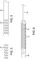
- FIG. 1 shows an implantable device 20, in this case a stent or stent-graft, mounted on a catheter 22 and constrained in a deployment apparatus 24 of the present invention.
- the deployment apparatus 24 comprises an everted traction tube sheath element 26 having an outer layer 28 and an inner layer 30. Contained within the outer layer 28 and the inner layer 30 of the sheath element 26 is a constraining member 32.
- the deployment apparatus 24 includes a first deployment line 34 operatively coupled to actuate the sheath 26 and a second deployment line 36 operatively coupled to actuate the constraining member 32.
- the sheath element 26 is constructed from a thin, flexible material that is adapted to surround and protect the implantable device.
- the flexible material should have sufficient longitudinal tensile strength so that it can serve as a traction tube to help pull the implantable device 20 through compaction apparatus and into the constraining member 32 during the manufacturing process.
- the flexible material should also have sufficient coverage and structural integrity to protect any bioactive coating or other surface treatment on the implantable device until the device is ultimately deployed in vivo. It may further be desirable for the flexible sheath to be constructed from a lubricious material that can aid in the manufacturing process described below.
- the sheath element 26 is not required to provide any significant constraint to the implantable device 20 as that function, if required, may be primarily provided by the constraining member 32. As such, the sheath element 26 may be constructed from very thin and flexible material that exhibits some degree of radial compliance. In fact, it may be desirable for the sheath element 26 undergo necking when under longitudinal tension so as to aid in the compaction process during manufacturing.
- the flexible material of the sheath element 26 may be formed from a variety of different materials, including without limitation: a continuous tube or sheet of material; a woven, knitted, or other fabric material; non-woven materials such as a felt; or a composite of two or more different materials.
- Suitable materials for use as a sheath 26 include tubes or sheets of material that may comprise but are not limited to: polytetrafluoroethylene (PTFE), expanded PTFE, polyester, polyethylene, nylon, rayon, polyimide, polyamide, polypropylene, and/or polyurethane.
- the sheath element 26 may be formed from a radially distensible material and/or it may be constructed in a wide variety of configurations.
- the material may be radially distensible, or radially necking, and/or have a wide range of strength or other properties.
- it may be beneficial to construct the sheath element in the form of a pleated sheath or a helically pleated sheath so as to assist in radial compliance or release of the device.
- the sheath element 26 is constructed from a continuous tube that is split at its trailing end, at point 37 in FIG. 1 , so as to form the first deployment line 34 from the same material as the sheath 26.
- the deployment line 34 may be formed by, for example, spirally winding, heating, or otherwise manipulating the split tube into thread structure.
- other materials such as a thread of polyamide, polyimide, PTFE, ePTFE, polyester or similar material, may be used alone or added to the split tube to provide a more robust deployment line construct.
- a suitable sheath element 26 may comprise a tubular sheath of expanded PTFE with a thickness of approximately 0.0015 to 0.15 mm, a longitudinal tensile strength of approximately 0.5 to 10 kgf.
- the sheath should have sufficient toughness to withstand any strains that may be applied by the constrained device (e.g., forces from stent apices, fins, anchors, etc.). As is explained below, for some applications it may be desirable for the sheath to have the ability to neck to an intermediate diameter when longitudinal tension is applied to the sheath.
- the sheath may be formed from any suitable base material, including without limitation a tube, sheet, and/or fibers (e.g., weave or braid of material).
- the constraining member 32 serves to provide the effective constraint for the implantable device 20.
- the constraining member 32 should be formed from a relatively non-compliant material that will resist any expansion force delivered by the implantable device 20.
- the constraining member 32 may be formed from a variety of different materials, including without limitation: a continuous tube or sheet of material; a woven, knitted, or other fabric material; non-woven materials such as a felt; or a composite of two or more different materials. Additionally, it may be beneficial to construct the constraining member 32 in the form of a pleated sheath or a helically pleated sheath, such as that disclosed in US Patent 8,845,712 to Irwin et al.
- Suitable materials for use as a constraining member 32 include tubes, sheets, or fibers of material that may comprise but are not limited to: polytetrafluoroethylene (PTFE), expanded PTFE, polyester, polyethylene, nylon, rayon, polyimide, polyamide, polypropylene, and/or polyurethane.
- PTFE polytetrafluoroethylene
- expanded PTFE polyester
- polyethylene polyethylene
- nylon nylon
- rayon polyimide
- polyamide polyamide
- polypropylene polyurethane
- the constraining member 32 may be effectively formed from a filamentary material, such that described in US Patent 6,315,792 to Armstrong et al. ("Armstrong et al. Patent").
- the knitted constraining members described in that patent provide very effective device constraint yet easily unravel from the implantable device during deployment.
- the Armstrong et al. Patent's constraints have proven to be very accurate and effective in implantable device delivery and deployment.
- significant benefits have been demonstrated. It has been determined that if the filamentary constraints described in the Armstrong et al.
- the fibers can snag on features of some implantable device constructions (e.g., certain forms of anchors, barbs, stent apices, etc.), which can create difficulties in mounting the constraint during manufacture and/or in releasing the constraint during deployment.
- the sheath element 26 serves to cover and isolate any problematic features on the implantable device 20 so that the constraining member 32 can be readily mounted on the implantable device 20 during manufacture and then readily removed from the implantable device 20 during deployment. This benefit greatly enhances the types of implantable devices that can now be successfully deployed using the apparatus of the Armstrong et al. Patent.
- the second deployment line 36 may comprise the same material as the constraining member 26, such as when the constraining member 26 is formed in accordance with certain embodiments of the Armstrong et al. Patent.
- other materials such as a thread of polyamide, polyimide, PTFE, ePTFE, polyester or similar material, may be used alone or added to the deployment line 36 to provide a more robust construct.
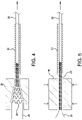
- FIG. 2 illustrates an implantable device 20, such as a stent or stent-graft, prior to mounting into the deployment apparatus 24 of the present invention.
- the implantable device 20 is placed within sheath element 26.
- the sheath element 26 and implantable device 20 combination illustrated in FIG 3 is drawn through a funnel 38 into a constraining member 32.
- the sheath element 26 is serving as a traction tube to provide a smooth and even surface to help ease the implantable device 20 through the funnel 38 and into the constraining member 32.
- any coating that may be applied to the implantable device 20 is thus protected from abrasion from the funnel 38 and constraining member 32.
- the necking force further assists in the compaction of the implantable device 20.
- the sheath element 26 is also isolating the implantable device 20 from the forces necessary to pull the device 20 through the funnel 38 and into the constraining member 32.
- tether lines would typically be applied to one end of the implantable device 20 in order to pull it through a funnel into a constraint.
- an implantable device must be constructed from materials and in a manner that allows it to withstand the substantial longitudinal forces necessary to compact it to its delivery dimensions (that is, if the implantable device is not sufficiently robust, it will be damaged under the forces of the tether lines during the compaction process). The compaction forces become significantly greater for longer implantable device constructs and when greater compaction ratios are undertaken.
- the sheath member of the present invention By using the sheath member of the present invention to apply traction forces along the entire length of the implantable device, it is possible to effectively compact implantable devices which would otherwise be too fragile to undergo compaction through conventional traction lines and/or to apply far greater compaction forces (and thus achieve far greater compaction ratios) than would previously be possible.
- the sheath element provides augmented axial strength to the implantable device during the compaction and loading processes.
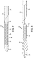
- FIG. 5 An alternative compaction process is illustrated in FIG. 5 .
- the sheath element 26 and implantable device 20 combination illustrated in FIG 3 is compacted by a compression apparatus 40, such as a radial crush device.
- the sheath element 26 facilitates the compacted implantable device to be more readily pulled out of the compression apparatus and into constraining member 32, with all of the benefits previous noted.
- the constrained device 20 may then be mounted on a delivery catheter 22 and the extra sheath element 26 may then be everted back over the constraining member 32 so as to sandwich the constraining member 32 within the inner layer 30 and outer layer 28 of the sheath element 26.
- Deployment line 34 may then be attached to or formed out of the sheath element 26.
- deployment line 36 may then be attached to or formed from constraining member 32 (for example, if the constraining member 32 is constructed from a knitted material, such as that described in the Armstrong et al. Patent, the deployment line 36 may comprise an cord formed from the unraveled constraining member 32).
- sheath element 26 may also be employed as a single layer.
- the benefits of employing a single layer sheath element are the opportunity to provide reduced delivery profile and decreased length of deployment line.
- the implantable device 20 and deployment apparatus 24 can be delivered to a desired treatment site in a patient in a conventional manner. It should be appreciated, however, that the encapsulation of the implantable device 20 within the sheath element 26 provides additional protection to the implantable device 20 during the delivery process.
- an implantable device 20 is provided with a drug or other bioactive coating, it is desirable that the coating is not exposed prior to reaching the intended deployment site.
- drug coatings will necessarily be exposed to blood and tissue long before reaching the intended deployment site, which can lead to possible abrasion of the coating from the device and unintended release of the bioactive materials in undesirable locations in the body.
- the sheath member 26 of the present invention the bioactive coating can be safeguarded against damage or premature release independent of how open the structure of the constraining devices may be.
- the device 20 can be released by actuating the two deployment lines 34 and 36, with each of the constraining member 32 and the sheath element 26 pulling away from the device upon actuation. This process is illustrated in FIG. 8 , with implantable device 20 shown beginning to deploy from the deployment apparatus 24.
- the sheath element 26 and the constraining member 32 may be constructed of different materials and comprise different forms, they are unlikely to retract at the same rate or in the same manner. Additionally, depending on construction, the deployment lines may not actuate at linear rates, thus requiring some degree of modulation of the rate of actuation of each of the lines. This presents the clinician with an undesirable challenge of trying to actuate the two deployment lines 34 and 36 simultaneously but at different rates.
- the present inventors have determined that this challenge can be fully addressed by employing one of a variety of differential mechanisms that allow the clinician to apply a single deployment force to the deployment apparatus 24 while the differential mechanism automatically modulates the rate of actuation of each of the deployment lines 34 and 36.
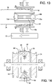
- FIG. 9 through FIG. 12 illustrate various apparatus that may be used to effectuate simultaneous removal of multiple traction lines that may be employed with the present invention.
- FIG. 9 illustrates the simplest form of differential whereby a the two deployment lines 34 and 36 are attached together at their terminal ends 42 and 44, respectively, and a pulley 46 is employed so that varying retraction rates on each of the deployment lines 34, 36 are instantly accommodated. The clinician simply applies a single deployment force 48 to the pulley and the sheath element and constraining member will retract at the same rate while any rate differential between the two are corrected by the pulley 46.
- FIG. 10 illustrates another form of differential whereby any difference in rate of withdrawal is pre-calculated and different fixed ratio pulleys 50, 52 are used to withdraw each of the deployment lines 34, 36 at their predetermined rates.
- FIG. 11 illustrates still another form of differential whereby a spring or other passive displacement mechanism 54 is associated with the deployment line 34 that is determined to require the most slack during deployment (that is, the deployment line that needs to be withdrawn slower). In this manner, the clinician can pull both lines at an even rate but the lines will effectively withdraw at their appropriate differential rates.
- FIG. 12 illustrates yet another form of differential whereby a clutch drive 56 is employed so that a driven pulley 58 takes up one of the deployment lines 36 at a set rate and a friction interface 60 between the driven pulley 58 and a second pulley 62 provides a clutch mechanism so that deployment line 34 will accumulate at a slower rate of speed.
- FIG. 13 A more sophisticated differential mechanism is illustrated in FIG. 13 .
- two pulleys 64, 66 are provided, each associated with deployment lines 34, 36, respectively.
- Pulley bevel gears 68a, 68b and planetary bevel gears 70a, 70b are mounted between the two pulleys 64, 66 so as to accommodate different rates of actuation of each of the pulleys 64, 66.
- a clinician-actuated thumb wheel 72 is provided to actuate the planetary gears through a center shaft with thumb wheel fixed at one end, and similarly to the clutch mechanism illustrated in FIG. 12 , the planetary gears 70a, 70b serve to accommodate different actuation rates between the two pulleys 64, 66.
- the bevel gears may be chosen to actuate each of the pulleys at their appropriate rates. For example, the sum of rotation of pulleys 64 and 66 can be established to be, for instance, 2x the input rotation of the thumb wheel 72.
- pulleys 74 and 76 are each associated with each of the deployment lines (not shown) and are attached, respectively, to ring gears 78, 80.
- Planetary gears 82, 84 are each provided with a clinician-actuated thumb wheel 86 that engages directly with the planetary gears.
- implantable device may be beneficial to transfer the implantable device to an intermediate compacted diameter prior to final compaction and mounting of the implantable device for delivery.
- a thinner and less robust sheath may be used for final device compaction and delivery, which may allow for desirable smaller device delivery dimensions.
- One method of accomplishing is to modify the mounting procedure illustrated in FIG. 2 to 6 , above, with additional process steps as illustrated in FIG. 15 to 18 .
- FIG. 15 the sheath element 26 and implantable device 20 combination illustrated in FIG 3 is drawn into a transfer funnel 88, with a segment 90 of the sheath element 26 everted over the transfer funnel 88.
- the compaction of the implantable device 20 into the transfer funnel 88 may be accomplished by applying tension 92 to the segment 90 so as to draw the sheath 26 and device 20 into the funnel 88.
- the implantable device 20 is positioned at the tip 94 of the transfer funnel 80, the device is ready for transfer.
- FIG. 16 shows a second sheath element 96 that is everted over a transfer tube 98.
- the second sheath element 96 is configured to be a diameter smaller than the diameter of sheath element 26.
- the transfer tube 98 is constructed from an essentially non-compliant material, such as a metal or plastic hypotube.
- the transfer tube 98 has a diameter that is approximately equal to that of the tip 94 of the transfer funnel 88.
- a portion 100 of the second sheath on the outside of the transfer tube 98 may be compacted or "scrunched" to make actuation of the second sheath easier in the transfer step described below.
- the implantable device 20, sheath element 26, and transfer funnel 88 combination shown in FIG. 15 is placed in abutted orientation with the second sheath element 96 and transfer tube 98 combination shown in FIG. 16 , as is shown in FIG 17 .
- the implantable device 20 will transfer from the transfer funnel 88 and sheath element 26 into the transfer tube 98 and second sheath element 96. This transfer is shown partially completed in FIG. 17 .
- the device 20 and second sheath 98 can be removed from the transfer tube, as is shown in FIG. 18 .
- the implantable device 20 is now contained at a small diameter and/or contained in a sheath with thinner wall thickness than the device and sheath illustrated in FIG 3 .
- the combined device and sheath can be further processed as previously described with respect to FIG. 4 through 6 .
- the present invention may be practiced through a number of ways whereby the implantable device may be partially compacted to one or more intermediate diameters during the manufacturing process.
- the present invention provides many benefits over prior medical device deployment apparatus, including without limitation:
- the present invention provides a delivery system that protects medical device during delivery in a body while providing simple, accurate, and reliable device deployment that is scalable to work on a wide variety of implantable device forms and sizes.
- the delivery system is configured so that loading and deployment forces are not directly related to device diameter, length, or design, thus allowing a more universal delivery system across various delivered device configurations and product lines.
- forces required to constrain implantable devices and deploy implantable devices can be decoupled from the length and other properties of the implantable devices.
- deployment forces may be smoother during delivery so as to minimize catheter movement (for example, increases in delivery force due to adverse interaction between the implantable device and the constraint can be avoided).
- the present invention can accommodate deployment of devices with irregular features (e.g., scallops, barbs, anchors, apices, and other features that may otherwise interfere with smooth operation of deployment apparatus).
- sheath element may help reduce device delivery profiles, both by allowing compaction forces to be decoupled from device longitudinal tensile strength and by providing a smoother and possibly more lubricious surface on the outside of the implantable device to allow for easier compaction of the device.
- the present invention also allows for lower implantable device mass and lower profile.
- the present invention can be configured so as to contain delivery lines within a sheath element in order to reduce or eliminate "bow-stringing" of the line during deployment.
- the present invention imparts minimal stress to the implantable device. For drug delivery devices, this can reduce drug loss and particulation during handling of the device in both manufacture and use.
- the encapsulation of the device can reduce or eliminate contact between device and tooling during device loading and mounting and also may isolate the device from surface shear and other damage during delivery and deployment.
Landscapes
- Health & Medical Sciences (AREA)
- Biomedical Technology (AREA)
- Engineering & Computer Science (AREA)
- Life Sciences & Earth Sciences (AREA)
- General Health & Medical Sciences (AREA)
- Animal Behavior & Ethology (AREA)
- Heart & Thoracic Surgery (AREA)
- Veterinary Medicine (AREA)
- Public Health (AREA)
- Vascular Medicine (AREA)
- Cardiology (AREA)
- Transplantation (AREA)
- Oral & Maxillofacial Surgery (AREA)
- Surgery (AREA)
- Molecular Biology (AREA)
- Medical Informatics (AREA)
- Nuclear Medicine, Radiotherapy & Molecular Imaging (AREA)
- Reproductive Health (AREA)
- Gastroenterology & Hepatology (AREA)
- Pulmonology (AREA)
- Prostheses (AREA)
- Media Introduction/Drainage Providing Device (AREA)
- Infusion, Injection, And Reservoir Apparatuses (AREA)
- Surgical Instruments (AREA)
Priority Applications (2)
| Application Number | Priority Date | Filing Date | Title |
|---|---|---|---|
| EP22166820.5A EP4049632B1 (en) | 2014-03-06 | 2015-03-06 | Implantable medical device constraint and deployment apparatus |
| EP25194594.5A EP4620435A3 (en) | 2014-03-06 | 2015-03-06 | Implantable medical device constraint and deployment apparatus |
Applications Claiming Priority (3)
| Application Number | Priority Date | Filing Date | Title |
|---|---|---|---|
| US201461949100P | 2014-03-06 | 2014-03-06 | |
| US14/639,699 US10966850B2 (en) | 2014-03-06 | 2015-03-05 | Implantable medical device constraint and deployment apparatus |
| PCT/US2015/019271 WO2015134917A2 (en) | 2014-03-06 | 2015-03-06 | Implantable medical device constraint and deployment apparatus |
Related Child Applications (2)
| Application Number | Title | Priority Date | Filing Date |
|---|---|---|---|
| EP25194594.5A Division EP4620435A3 (en) | 2014-03-06 | 2015-03-06 | Implantable medical device constraint and deployment apparatus |
| EP22166820.5A Division EP4049632B1 (en) | 2014-03-06 | 2015-03-06 | Implantable medical device constraint and deployment apparatus |
Publications (2)
| Publication Number | Publication Date |
|---|---|
| EP3113728A2 EP3113728A2 (en) | 2017-01-11 |
| EP3113728B1 true EP3113728B1 (en) | 2022-05-11 |
Family
ID=54016261
Family Applications (3)
| Application Number | Title | Priority Date | Filing Date |
|---|---|---|---|
| EP25194594.5A Pending EP4620435A3 (en) | 2014-03-06 | 2015-03-06 | Implantable medical device constraint and deployment apparatus |
| EP15711374.7A Active EP3113728B1 (en) | 2014-03-06 | 2015-03-06 | Implantable medical device constraint and deployment apparatus |
| EP22166820.5A Active EP4049632B1 (en) | 2014-03-06 | 2015-03-06 | Implantable medical device constraint and deployment apparatus |
Family Applications Before (1)
| Application Number | Title | Priority Date | Filing Date |
|---|---|---|---|
| EP25194594.5A Pending EP4620435A3 (en) | 2014-03-06 | 2015-03-06 | Implantable medical device constraint and deployment apparatus |
Family Applications After (1)
| Application Number | Title | Priority Date | Filing Date |
|---|---|---|---|
| EP22166820.5A Active EP4049632B1 (en) | 2014-03-06 | 2015-03-06 | Implantable medical device constraint and deployment apparatus |
Country Status (10)
| Country | Link |
|---|---|
| US (3) | US10966850B2 (enExample) |
| EP (3) | EP4620435A3 (enExample) |
| JP (3) | JP6870986B2 (enExample) |
| KR (1) | KR20160130268A (enExample) |
| CN (2) | CN110051399B (enExample) |
| AU (2) | AU2015226907B2 (enExample) |
| BR (1) | BR112016020044A8 (enExample) |
| CA (2) | CA2940704C (enExample) |
| ES (1) | ES2924403T3 (enExample) |
| WO (1) | WO2015134917A2 (enExample) |
Families Citing this family (29)
| Publication number | Priority date | Publication date | Assignee | Title |
|---|---|---|---|---|
| US10213329B2 (en) | 2011-08-12 | 2019-02-26 | W. L. Gore & Associates, Inc. | Evertable sheath devices, systems, and methods |
| US9782282B2 (en) | 2011-11-14 | 2017-10-10 | W. L. Gore & Associates, Inc. | External steerable fiber for use in endoluminal deployment of expandable devices |
| US9877858B2 (en) | 2011-11-14 | 2018-01-30 | W. L. Gore & Associates, Inc. | External steerable fiber for use in endoluminal deployment of expandable devices |
| US9375308B2 (en) | 2012-03-13 | 2016-06-28 | W. L. Gore & Associates, Inc. | External steerable fiber for use in endoluminal deployment of expandable devices |
| US9907641B2 (en) | 2014-01-10 | 2018-03-06 | W. L. Gore & Associates, Inc. | Implantable intraluminal device |
| US9763819B1 (en) | 2013-03-05 | 2017-09-19 | W. L. Gore & Associates, Inc. | Tapered sleeve |
| US10966850B2 (en) | 2014-03-06 | 2021-04-06 | W. L. Gore & Associates, Inc. | Implantable medical device constraint and deployment apparatus |
| US11712230B2 (en) | 2014-05-02 | 2023-08-01 | W. L. Gore & Associates, Inc. | Occluder and anastomosis devices |
| US11439396B2 (en) | 2014-05-02 | 2022-09-13 | W. L. Gore & Associates, Inc. | Occluder and anastomosis devices |
| US20150313595A1 (en) | 2014-05-02 | 2015-11-05 | W. L. Gore & Associates, Inc. | Anastomosis Devices |
| JP6883115B2 (ja) | 2017-03-08 | 2021-06-09 | ダブリュ.エル.ゴア アンド アソシエイツ,インコーポレイティドW.L. Gore & Associates, Incorporated | 角度付け用ステアリングワイヤーアタッチ |
| AU2018230487B2 (en) | 2017-03-09 | 2020-02-27 | Medtronic Vascular Inc. | Tension management devices for stented prosthesis delivery device |
| US11724075B2 (en) * | 2017-04-18 | 2023-08-15 | W. L. Gore & Associates, Inc. | Deployment constraining sheath that enables staged deployment by device section |
| US10406012B2 (en) * | 2017-04-26 | 2019-09-10 | Medtronic Vascular, Inc. | Mechanical delivery systems for an endovascular device |
| US11540933B2 (en) | 2017-10-11 | 2023-01-03 | W. L. Gore & Associates, Inc. | Implantable medical device constraint and deployment apparatus |
| US10857015B2 (en) * | 2018-03-21 | 2020-12-08 | Medtronic Vascular, Inc. | Variable speed retraction mechanism delivery system and method |
| US12004981B2 (en) * | 2018-06-14 | 2024-06-11 | W. L. Gore & Associates, Inc. | Systems and methods for on-device constraining mechanism construction |
| EP3817687A1 (en) * | 2018-07-06 | 2021-05-12 | Muffin Incorporated d/b/a Cook Advanced Technologies | Storage devices, loading devices, delivery systems kits, and associated methods |
| CA3108510C (en) * | 2018-08-31 | 2023-06-20 | W. L. Gore & Associates, Inc. | Pivot delivery system for implantable medical device |
| CN112789012B (zh) * | 2018-10-05 | 2024-06-07 | W.L.戈尔及同仁股份有限公司 | 约束机构和相关联的方法 |
| AU2019355988B2 (en) | 2018-10-05 | 2022-10-20 | W. L. Gore & Associates, Inc. | Constraining mechanisms for selective deployment and associated methods |
| US11690743B2 (en) * | 2019-02-15 | 2023-07-04 | Boston Scientific Scimed, Inc. | Stent delivery system |
| JP7329059B2 (ja) * | 2019-02-22 | 2023-08-17 | ダブリュ.エル.ゴア アンド アソシエイツ,インコーポレイティド | 作動ライン格納システム及び方法 |
| US12433775B2 (en) | 2019-05-10 | 2025-10-07 | W. L. Gore & Associates, Inc. | Constraining mechanisms for selective deployment and associated methods |
| AU2019445546B2 (en) | 2019-05-10 | 2022-12-15 | W. L. Gore & Associates, Inc. | Constraining mechanisms for selective deployment and associated methods |
| US11259944B2 (en) * | 2019-06-27 | 2022-03-01 | Cook Medical Technologies Llc | Stent deployment system with unwrapping deployment constraint |
| CN116056668A (zh) * | 2020-06-11 | 2023-05-02 | 爱德华兹生命科学公司 | 用于假体瓣膜递送设备的刚性编织物构件 |
| CN116847902A (zh) * | 2020-12-23 | 2023-10-03 | 波士顿科学国际有限公司 | 以高摩擦编织物促进装置的递送 |
| CN117045303B (zh) * | 2023-08-16 | 2024-02-02 | 南京思脉德医疗科技有限公司 | 一种栓塞弹簧圈输送系统的换丝装置 |
Citations (2)
| Publication number | Priority date | Publication date | Assignee | Title |
|---|---|---|---|---|
| US6315792B1 (en) * | 1998-06-15 | 2001-11-13 | Gore Enterprise Holdings, Inc. | Remotely removable covering and support |
| US20050240254A1 (en) * | 2004-04-27 | 2005-10-27 | Michael Austin | Stent delivery system |
Family Cites Families (221)
| Publication number | Priority date | Publication date | Assignee | Title |
|---|---|---|---|---|
| NL8220336A (nl) | 1981-09-16 | 1984-01-02 | Wallsten Hans Ivar | Inrichting voor toepassing in bloedvaten of andere moeilijk toegankelijke plaatsen, en haar gebruik. |
| US4606347A (en) | 1983-03-25 | 1986-08-19 | Thomas J. Fogarty | Inverted balloon catheter having sealed through lumen |
| ES8705239A1 (es) | 1984-12-05 | 1987-05-01 | Medinvent Sa | Un dispositivo para implantar,mediante insercion en un lugarde dificil acceso, una protesis sustancialmente tubular y radialmente expandible |
| SE455834B (sv) | 1986-10-31 | 1988-08-15 | Medinvent Sa | Anordning for transluminal implantation av en i huvudsak rorformig, radiellt expanderbar protes |
| US4921479A (en) | 1987-10-02 | 1990-05-01 | Joseph Grayzel | Catheter sheath with longitudinal seam |
| US5064435A (en) | 1990-06-28 | 1991-11-12 | Schneider (Usa) Inc. | Self-expanding prosthesis having stable axial length |
| US5389100A (en) | 1991-11-06 | 1995-02-14 | Imagyn Medical, Inc. | Controller for manipulation of instruments within a catheter |
| FR2688401B1 (fr) | 1992-03-12 | 1998-02-27 | Thierry Richard | Endoprothese expansible pour organe tubulaire humain ou animal, et outil de mise en place. |
| US5425765A (en) | 1993-06-25 | 1995-06-20 | Tiefenbrun; Jonathan | Surgical bypass method |
| US5445646A (en) * | 1993-10-22 | 1995-08-29 | Scimed Lifesystems, Inc. | Single layer hydraulic sheath stent delivery apparatus and method |
| US5989280A (en) * | 1993-10-22 | 1999-11-23 | Scimed Lifesystems, Inc | Stent delivery apparatus and method |
| US5571135A (en) * | 1993-10-22 | 1996-11-05 | Scimed Life Systems Inc. | Stent delivery apparatus and method |
| US5824041A (en) | 1994-06-08 | 1998-10-20 | Medtronic, Inc. | Apparatus and methods for placement and repositioning of intraluminal prostheses |
| EP0686379B2 (en) | 1994-06-08 | 2007-03-28 | Cardiovascular Concepts, Inc. | Vascular graft |
| US6264684B1 (en) | 1995-03-10 | 2001-07-24 | Impra, Inc., A Subsidiary Of C.R. Bard, Inc. | Helically supported graft |
| US5647857A (en) * | 1995-03-16 | 1997-07-15 | Endotex Interventional Systems, Inc. | Protective intraluminal sheath |
| ATE232067T1 (de) * | 1995-04-14 | 2003-02-15 | Boston Scient Ltd | Stentanbringungsvorrichtung mit rollmembran |
| US5534007A (en) | 1995-05-18 | 1996-07-09 | Scimed Life Systems, Inc. | Stent deployment catheter with collapsible sheath |
| DE19531659C2 (de) | 1995-08-29 | 1998-07-02 | Ernst Peter Prof Dr M Strecker | Stent |
| GB9518400D0 (en) | 1995-09-08 | 1995-11-08 | Anson Medical Ltd | A surgical graft/stent system |
| JP2000503559A (ja) | 1995-12-14 | 2000-03-28 | ゴア エンタープライズ ホールディングス,インコーポレイティド | ステント移植片を展開する装置並びに方法 |
| US6042605A (en) | 1995-12-14 | 2000-03-28 | Gore Enterprose Holdings, Inc. | Kink resistant stent-graft |
| US5928279A (en) | 1996-07-03 | 1999-07-27 | Baxter International Inc. | Stented, radially expandable, tubular PTFE grafts |
| CA2211249C (en) | 1996-07-24 | 2007-07-17 | Cordis Corporation | Balloon catheter and methods of use |
| CA2263672A1 (en) | 1996-08-26 | 1998-03-05 | Transvascular, Inc. | Methods and apparatus for transmyocardial direct coronary revascularization |
| US6254628B1 (en) * | 1996-12-09 | 2001-07-03 | Micro Therapeutics, Inc. | Intracranial stent |
| EP2298241A3 (en) | 1996-12-03 | 2011-11-02 | Atrium Medical Corporation | Multi-stage prothesis |
| US6352561B1 (en) | 1996-12-23 | 2002-03-05 | W. L. Gore & Associates | Implant deployment apparatus |
| US6004328A (en) | 1997-06-19 | 1999-12-21 | Solar; Ronald J. | Radially expandable intraluminal stent and delivery catheter therefore and method of using the same |
| US20100030256A1 (en) | 1997-11-12 | 2010-02-04 | Genesis Technologies Llc | Medical Devices and Methods |
| AUPP083597A0 (en) | 1997-12-10 | 1998-01-08 | William A Cook Australia Pty Ltd | Endoluminal aortic stents |
| DE69928224T2 (de) | 1998-01-26 | 2006-08-03 | Anson Medical Ltd., Didcot | Verstärktes implantat |
| US6203550B1 (en) | 1998-09-30 | 2001-03-20 | Medtronic, Inc. | Disposable delivery device for endoluminal prostheses |
| US6059813A (en) * | 1998-11-06 | 2000-05-09 | Scimed Life Systems, Inc. | Rolling membrane stent delivery system |
| US6544278B1 (en) | 1998-11-06 | 2003-04-08 | Scimed Life Systems, Inc. | Rolling membrane stent delivery system |
| US6113608A (en) | 1998-11-20 | 2000-09-05 | Scimed Life Systems, Inc. | Stent delivery device |
| AU768071B2 (en) * | 1999-01-22 | 2003-12-04 | W.L. Gore & Associates, Inc. | Low profile stent and graft combination |
| US6398758B1 (en) | 1999-02-16 | 2002-06-04 | Stephen C. Jacobsen | Medicament delivery system |
| JP4138144B2 (ja) | 1999-03-31 | 2008-08-20 | テルモ株式会社 | 管腔内留置物 |
| US6428550B1 (en) | 1999-05-18 | 2002-08-06 | Cardica, Inc. | Sutureless closure and deployment system for connecting blood vessels |
| US6478814B2 (en) | 1999-06-14 | 2002-11-12 | Scimed Life Systems, Inc. | Stent securement sleeves and optional coatings and methods of use |
| US6364904B1 (en) | 1999-07-02 | 2002-04-02 | Scimed Life Systems, Inc. | Helically formed stent/graft assembly |
| US6533806B1 (en) | 1999-10-01 | 2003-03-18 | Scimed Life Systems, Inc. | Balloon yielded delivery system and endovascular graft design for easy deployment |
| US6383171B1 (en) * | 1999-10-12 | 2002-05-07 | Allan Will | Methods and devices for protecting a passageway in a body when advancing devices through the passageway |
| US7201770B2 (en) * | 2000-03-21 | 2007-04-10 | Cordis Corporation | Everting balloon stent delivery system having tapered leading edge |
| KR20020093109A (ko) * | 2000-05-02 | 2002-12-12 | 윌슨-쿡 메디컬 인크. | 뒤집힐 수 있는 슬리브가 구비된 카테터 o.t.l.용삽입기 장치 |
| SE522805C2 (sv) * | 2000-06-22 | 2004-03-09 | Jan Otto Solem | Stentappliceringssystem |
| US6607552B1 (en) | 2000-09-18 | 2003-08-19 | Scimed Life Systems, Inc. | Rolling socks |
| US6733520B2 (en) | 2000-09-22 | 2004-05-11 | Scimed Life Systems, Inc. | Sandwich striped sleeve for stent delivery |
| US6645242B1 (en) | 2000-12-11 | 2003-11-11 | Stephen F. Quinn | Bifurcated side-access intravascular stent graft |
| US6899727B2 (en) * | 2001-01-22 | 2005-05-31 | Gore Enterprise Holdings, Inc. | Deployment system for intraluminal devices |
| US6733521B2 (en) | 2001-04-11 | 2004-05-11 | Trivascular, Inc. | Delivery system and method for endovascular graft |
| US6676693B1 (en) | 2001-06-27 | 2004-01-13 | Advanced Cardiovascular Systems, Inc. | Apparatus and method for delivering a self-expanding stent |
| US20030004561A1 (en) | 2001-06-28 | 2003-01-02 | Steve Bigus | Peeling sheath for self-expanding stent |
| US6949112B1 (en) | 2001-07-26 | 2005-09-27 | Advanced Cardiovascular Systems, Inc. | Medical device formed of polyester copolymer |
| AUPR847301A0 (en) | 2001-10-26 | 2001-11-15 | Cook Incorporated | Endoluminal prostheses for curved lumens |
| US20060292206A1 (en) | 2001-11-26 | 2006-12-28 | Kim Steven W | Devices and methods for treatment of vascular aneurysms |
| US7147656B2 (en) * | 2001-12-03 | 2006-12-12 | Xtent, Inc. | Apparatus and methods for delivery of braided prostheses |
| US7147661B2 (en) | 2001-12-20 | 2006-12-12 | Boston Scientific Santa Rosa Corp. | Radially expandable stent |
| US20100016943A1 (en) | 2001-12-20 | 2010-01-21 | Trivascular2, Inc. | Method of delivering advanced endovascular graft |
| US6699273B2 (en) | 2002-02-04 | 2004-03-02 | Scimed Life Systems, Inc. | Sleeve welding collar |
| GB0203177D0 (en) | 2002-02-11 | 2002-03-27 | Anson Medical Ltd | An improved control mechanism for medical catheters |
| JP4208075B2 (ja) | 2002-03-25 | 2009-01-14 | クック インコーポレイティド | 二股の/枝分かれした血管用プロテーゼ |
| US6911039B2 (en) * | 2002-04-23 | 2005-06-28 | Medtronic Vascular, Inc. | Integrated mechanical handle with quick slide mechanism |
| EP2067499B1 (en) | 2002-04-25 | 2012-05-16 | The Board of Trustees of The Leland Stanford Junior University | Expandable guide sheath and apparatus and methods using such sheaths |
| US6830575B2 (en) * | 2002-05-08 | 2004-12-14 | Scimed Life Systems, Inc. | Method and device for providing full protection to a stent |
| AU2003243204B2 (en) | 2002-05-16 | 2008-09-18 | Cook Medical Technologies Llc | Flexible barb for anchoring a prosthesis |
| US20040097957A1 (en) * | 2002-10-18 | 2004-05-20 | Marc Jaker | Medical device, drug delivery and lab sampling system utilizing an inverting sheath technology |
| US20040087886A1 (en) | 2002-10-30 | 2004-05-06 | Scimed Life Systems, Inc. | Linearly expandable ureteral stent |
| GB0327306D0 (en) | 2003-11-24 | 2003-12-24 | Angiomed Gmbh & Co | Catheter device |
| US7625337B2 (en) | 2003-01-17 | 2009-12-01 | Gore Enterprise Holdings, Inc. | Catheter assembly |
| US7198636B2 (en) | 2003-01-17 | 2007-04-03 | Gore Enterprise Holdings, Inc. | Deployment system for an endoluminal device |
| US7753945B2 (en) | 2003-01-17 | 2010-07-13 | Gore Enterprise Holdings, Inc. | Deployment system for an endoluminal device |
| US7318836B2 (en) | 2003-03-11 | 2008-01-15 | Boston Scientific Scimed, Inc. | Covered stent |
| US8262671B2 (en) | 2003-03-14 | 2012-09-11 | Oscor Inc. | Vascular introducer having hemostatic valve with integral seal |
| US20050049675A1 (en) | 2003-03-28 | 2005-03-03 | Board Of Regents, The University Of Texas System | Medical devices and related methods |
| EP1608293B1 (en) | 2003-04-03 | 2015-06-03 | Cook Medical Technologies LLC | Deployment system for a branched stent graft |
| US7530963B2 (en) | 2003-04-24 | 2009-05-12 | Wisconsin Alumni Research Foundation | Method of maintaining patency of opening in third ventricle floor |
| ATE327589T1 (de) * | 2003-07-01 | 2006-06-15 | Cit Alcatel | Verfahren zur verhinderung der sättigung einer induktanzspule und induktanzspulenschaltung für die ausführung eines solchen verfahrens |
| US7651519B2 (en) | 2003-09-16 | 2010-01-26 | Cook Incorporated | Prosthesis deployment system |
| US20050059923A1 (en) | 2003-09-17 | 2005-03-17 | Ricardo Gamboa | Fenestration with intrinsic means of selective closure incorporated to a tubular body and used in interventional cardiovascular procedures |
| CA2540836C (en) | 2003-10-10 | 2012-01-24 | William A. Cook Australia Pty. Ltd. | Stent graft fenestration |
| EP1682041A2 (en) | 2003-10-10 | 2006-07-26 | QUADRI, Arshad | System and method for endoluminal grafting of bifurcated and branched vessels |
| US8012193B2 (en) | 2003-10-14 | 2011-09-06 | William A. Cook Australia Pty, Ltd | Introducer for an iliac side branch device |
| US7695508B2 (en) * | 2003-10-16 | 2010-04-13 | Minvasys Sa | Catheter system for stenting bifurcated vessels |
| US20050131515A1 (en) | 2003-12-16 | 2005-06-16 | Cully Edward H. | Removable stent-graft |
| US7468070B2 (en) * | 2004-01-23 | 2008-12-23 | Boston Scientific Scimed, Inc. | Stent delivery catheter |
| WO2005088437A1 (en) * | 2004-03-11 | 2005-09-22 | Redsky Mobile Inc. | Restricted user interface navigation |
| JP2006006648A (ja) | 2004-06-25 | 2006-01-12 | Terumo Corp | 血管接合具および血管接合装置 |
| US20050288766A1 (en) | 2004-06-28 | 2005-12-29 | Xtent, Inc. | Devices and methods for controlling expandable prostheses during deployment |
| US8308789B2 (en) * | 2004-07-16 | 2012-11-13 | W. L. Gore & Associates, Inc. | Deployment system for intraluminal devices |
| US7955370B2 (en) * | 2004-08-06 | 2011-06-07 | Boston Scientific Scimed, Inc. | Stent delivery system |
| US7393358B2 (en) * | 2004-08-17 | 2008-07-01 | Boston Scientific Scimed, Inc. | Stent delivery system |
| CN100352406C (zh) | 2004-08-17 | 2007-12-05 | 微创医疗器械(上海)有限公司 | 组合式可任意方向弯曲的覆膜支架 |
| US9706997B2 (en) | 2004-08-27 | 2017-07-18 | Rox Medical, Inc. | Device and method for establishing an artificial arterio-venous fistula |
| US7347868B2 (en) * | 2004-10-26 | 2008-03-25 | Baronova, Inc. | Medical device delivery catheter |
| US8262720B2 (en) * | 2004-12-02 | 2012-09-11 | Nitinol Development Corporation | Prosthesis comprising dual tapered stent |
| US7918880B2 (en) * | 2005-02-16 | 2011-04-05 | Boston Scientific Scimed, Inc. | Self-expanding stent and delivery system |
| US7828837B2 (en) | 2005-02-17 | 2010-11-09 | Khoury Medical Devices, LLC. | Vascular endograft |
| US7632296B2 (en) * | 2005-03-03 | 2009-12-15 | Boston Scientific Scimed, Inc. | Rolling membrane with hydraulic recapture means for self expanding stent |
| US7766959B2 (en) | 2005-03-25 | 2010-08-03 | Scimed Life Systems, Inc. | Variable length endovascular graft prosthesis adapted to prevent endoleaks |
| FR2885794B1 (fr) * | 2005-05-19 | 2007-08-17 | Perouse Soc Par Actions Simpli | Necessaire de largage d'un organe de traitement d'une cavite et procede de preparation d'un organe de traitement associe |
| US7938851B2 (en) | 2005-06-08 | 2011-05-10 | Xtent, Inc. | Devices and methods for operating and controlling interventional apparatus |
| EP2179709B1 (en) | 2005-08-17 | 2011-10-05 | C. R. Bard, Inc. | Variable speed stent delivery system |
| WO2007024964A1 (en) | 2005-08-22 | 2007-03-01 | Incept, Llc | Flared stents and apparatus and methods for making and using them |
| US20070142904A1 (en) | 2005-12-20 | 2007-06-21 | Boston Scientific Scimed, Inc. | Bifurcated stent with multiple locations for side branch access |
| TW200732412A (en) * | 2006-02-23 | 2007-09-01 | Pont Taiwan Ltd Du | Non-halogen composition having phosphor-containing epoxy resin |
| US20070208350A1 (en) * | 2006-03-06 | 2007-09-06 | Gunderson Richard C | Implantable medical endoprosthesis delivery systems |
| WO2007109621A2 (en) | 2006-03-20 | 2007-09-27 | Xtent, Inc. | Apparatus and methods for deployment of linked prosthetic segments |
| US9211206B2 (en) * | 2006-04-13 | 2015-12-15 | Medtronic Vascular, Inc. | Short handle for a long stent |
| US20080028139A1 (en) * | 2006-07-27 | 2008-01-31 | Cypher Robert E | Content-addressable memory that supports a priority ordering between banks |
| US9585743B2 (en) | 2006-07-31 | 2017-03-07 | Edwards Lifesciences Cardiaq Llc | Surgical implant devices and methods for their manufacture and use |
| US20080140173A1 (en) | 2006-08-07 | 2008-06-12 | Sherif Eskaros | Non-shortening wrapped balloon |
| GB0618516D0 (en) | 2006-09-20 | 2006-11-01 | Angiomed Ag | Hand-held actuator device |
| US8257431B2 (en) | 2006-11-01 | 2012-09-04 | Boston Scientific Scimed, Inc. | Multi-furcated ePTFE grafts and stent-graft prostheses and methods of making the same |
| AU2007317777B2 (en) | 2006-11-07 | 2012-08-02 | Cook Incorporated | Fenestrations for stent graft arrangements and stent graft including the same |
| US8052732B2 (en) | 2006-11-14 | 2011-11-08 | Medtronic Vascular, Inc. | Delivery system for stent-graft with anchoring pins |
| US20080140003A1 (en) * | 2006-12-06 | 2008-06-12 | Advanced Cardiovascular Systems, Inc. | Balloon catheter having a regrooming sheath and method for collapsing an expanded medical device |
| US20080167705A1 (en) * | 2007-01-10 | 2008-07-10 | Cook Incorporated | Short wire stent delivery system with splittable outer sheath |
| US8088154B2 (en) * | 2007-03-31 | 2012-01-03 | Cook Medical Technologies Llc | Medical device delivery system with sheath separation |
| US8764816B2 (en) | 2007-05-07 | 2014-07-01 | W. L. Gore & Associates, Inc. | Stent delivery and deployment system |
| US20080312662A1 (en) | 2007-06-13 | 2008-12-18 | Hickingbotham Dyson W | Self Sealing Cannula / Aperture Closure Cannula |
| US8540760B2 (en) | 2007-07-11 | 2013-09-24 | Cook Medical Technologies Llc | Tubular devices having reversible components for deployment of endoluminal occluders and related methods and systems |
| US8617114B2 (en) * | 2007-07-13 | 2013-12-31 | Abbott Cardiovascular Systems Inc. | Drug coated balloon catheter |
| US8690823B2 (en) * | 2007-07-13 | 2014-04-08 | Abbott Cardiovascular Systems Inc. | Drug coated balloon catheter |
| US9149379B2 (en) | 2007-07-16 | 2015-10-06 | Cook Medical Technologies Llc | Delivery device |
| US20090043376A1 (en) | 2007-08-08 | 2009-02-12 | Hamer Rochelle M | Endoluminal Prosthetic Conduit Systems and Method of Coupling |
| US20090099638A1 (en) | 2007-10-11 | 2009-04-16 | Med Institute, Inc. | Motorized deployment system |
| WO2009061882A1 (en) | 2007-11-07 | 2009-05-14 | Cook Incorporated | Method and apparatus for introducing expandable intraluminal prosthesis |
| US8328861B2 (en) | 2007-11-16 | 2012-12-11 | Trivascular, Inc. | Delivery system and method for bifurcated graft |
| US20090143760A1 (en) | 2007-11-30 | 2009-06-04 | Jacques Van Dam | Methods, Devices, Kits and Systems for Defunctionalizing the Gallbladder |
| US8845712B2 (en) * | 2008-01-15 | 2014-09-30 | W. L. Gore & Associates, Inc. | Pleated deployment sheath |
| US8758421B2 (en) * | 2008-01-30 | 2014-06-24 | Boston Scientific Scimed, Inc. | Medical systems and related methods |
| AU2009215163B2 (en) | 2008-02-11 | 2012-12-13 | Cook Incorporated | Curve forming apparatus and curvable stent graft |
| DE102008012113A1 (de) | 2008-03-02 | 2009-09-03 | Transcatheter Technologies Gmbh | Stent, welcher vom expandierten Zustand erneut im Durchmesser kontrolliert verringerbar ist |
| EP2278939B1 (en) | 2008-04-25 | 2021-04-14 | Endologix LLC | Stent graft delivery system |
| DE102008021060A1 (de) * | 2008-04-26 | 2009-10-29 | Biotronik Vi Patent Ag | Einführvorrichtung mit einer Freisetzeinrichtung zur Freisetzung eines von einem Katheter getragenen Gegenstandes sowie Freisetzeinrichtung einer Einführvorrichtung |
| WO2009145901A1 (en) | 2008-05-29 | 2009-12-03 | Med Institute, Inc. | Low profile composite endoluminal prostheses |
| TW201000160A (en) | 2008-06-25 | 2010-01-01 | Univ Nat Taiwan | The control system of catheter feeder |
| JP5134729B2 (ja) | 2008-07-01 | 2013-01-30 | エンドロジックス、インク | カテーテルシステム |
| WO2010003070A1 (en) * | 2008-07-02 | 2010-01-07 | Cook Incorporated | Deployment assembly and introducer |
| US20100003647A1 (en) * | 2008-07-04 | 2010-01-07 | Wendell Brown | System and Method for Automated Meal Recommendations |
| US8109985B2 (en) | 2008-07-23 | 2012-02-07 | Boston Scientific Scimed, Inc. | Occlusion crossing device and method |
| US7976574B2 (en) * | 2008-08-08 | 2011-07-12 | Advanced Cardiovascular Systems, Inc. | Delivery system with variable delivery rate for deploying a medical device |
| US8721714B2 (en) * | 2008-09-17 | 2014-05-13 | Medtronic Corevalve Llc | Delivery system for deployment of medical devices |
| US8790387B2 (en) * | 2008-10-10 | 2014-07-29 | Edwards Lifesciences Corporation | Expandable sheath for introducing an endovascular delivery device into a body |
| WO2010048052A1 (en) | 2008-10-22 | 2010-04-29 | Boston Scientific Scimed, Inc. | Shape memory tubular stent with grooves |
| GB2464978B (en) | 2008-10-31 | 2010-10-20 | Cook William Europ | Introducer for deploying a stent graft in a curved lumen |
| GB0822109D0 (en) | 2008-12-03 | 2009-01-07 | Angiomed Ag | Rectractable catheter |
| GB0822110D0 (en) | 2008-12-03 | 2009-01-07 | Angiomed Ag | Catheter sheath for implant delivery |
| JP5635997B2 (ja) * | 2008-12-03 | 2014-12-03 | アンジオメト・ゲーエムベーハー・ウント・コンパニー・メディツィンテクニク・カーゲー | 伸縮自在なカテーテル |
| GB0823716D0 (en) | 2008-12-31 | 2009-02-04 | Angiomed Ag | Stent delivery device with rolling stent retaining sheath |
| US8326437B2 (en) * | 2009-03-04 | 2012-12-04 | W. L. Gore & Associates, Inc. | Atraumatic lead removal sheath |
| US9301863B2 (en) | 2009-03-10 | 2016-04-05 | Medtronic Vascular, Inc. | Prosthesis delivery apparatus and methods |
| WO2010120671A1 (en) | 2009-04-15 | 2010-10-21 | Cook Incorporated | Everting deployment system and handle |
| US20110009943A1 (en) | 2009-07-09 | 2011-01-13 | Paul Ram H | Delivery system with medical device release by evertable sleeve |
| US8936634B2 (en) * | 2009-07-15 | 2015-01-20 | W. L. Gore & Associates, Inc. | Self constraining radially expandable medical devices |
| US8435282B2 (en) * | 2009-07-15 | 2013-05-07 | W. L. Gore & Associates, Inc. | Tube with reverse necking properties |
| US20110034987A1 (en) * | 2009-08-04 | 2011-02-10 | Kennedy Kenneth C | Roll sleeve mechanism for proximal release stent |
| US9060895B2 (en) | 2009-10-20 | 2015-06-23 | Cook Medical Technologies Llc | Rotational controlled deployment device |
| US20110118817A1 (en) * | 2009-11-17 | 2011-05-19 | Boston Scientific Scimed, Inc. | Stent delivery system |
| US20110118765A1 (en) | 2009-11-18 | 2011-05-19 | Aguirre Andres F | Anastomosis stent |
| GB0921236D0 (en) | 2009-12-03 | 2010-01-20 | Angiomed Ag | Stent device delivery system and method of making such |
| GB0921237D0 (en) | 2009-12-03 | 2010-01-20 | Angiomed Ag | Stent device delivery system and method of making such |
| US8016872B2 (en) * | 2009-12-22 | 2011-09-13 | Cook Medical Technologies Llc | Deployment and dilation with an expandable roll sock delivery system |
| DE102009060228B4 (de) | 2009-12-23 | 2014-12-04 | Acandis Gmbh & Co. Kg | Medizinische Vorrichtungen |
| US20120296408A1 (en) | 2010-01-25 | 2012-11-22 | Jones Donald K | Methods and systems for performing vascular reconstruction |
| US20110208292A1 (en) | 2010-02-19 | 2011-08-25 | Abbott Laboratories | Hinged sheath assembly and method of use |
| US9226826B2 (en) * | 2010-02-24 | 2016-01-05 | Medtronic, Inc. | Transcatheter valve structure and methods for valve delivery |
| US9119738B2 (en) | 2010-06-28 | 2015-09-01 | Colibri Heart Valve Llc | Method and apparatus for the endoluminal delivery of intravascular devices |
| US8337542B2 (en) * | 2010-07-14 | 2012-12-25 | Cook Medical Technologies Llc | Delivery system for simultaneous deployment of intraluminal device |
| EP2629706B1 (en) | 2010-10-21 | 2017-08-16 | Boston Scientific Scimed, Inc. | Stent delivery system with a rolling membrane |
| GB201017834D0 (en) * | 2010-10-21 | 2010-12-01 | Angiomed Ag | System to deliver a bodily implant |
| US9468547B2 (en) | 2010-11-11 | 2016-10-18 | W. L. Gore & Associates, Inc. | Deployment of endoluminal devices |
| US9414944B2 (en) * | 2010-11-11 | 2016-08-16 | W. L. Gore & Associates, Inc. | Deployment sleeve shortening mechanism |
| JP2012105188A (ja) | 2010-11-12 | 2012-05-31 | Sony Corp | 画像出力装置、画像出力方法、画像処理装置、画像処理方法、プログラム、および撮像装置 |
| US8753386B2 (en) | 2010-11-15 | 2014-06-17 | W. L. Gore & Associates, Inc. | Stent-graft having facing side branch portals |
| US20140018610A1 (en) * | 2010-12-20 | 2014-01-16 | Walter von Pechmann | Endoscopic mesh delivery system with integral mesh stabilizer and vaginal probe |
| US8657866B2 (en) * | 2010-12-22 | 2014-02-25 | Cook Medical Technologies Llc | Emergency vascular repair prosthesis deployment system |
| US8641752B1 (en) * | 2011-01-20 | 2014-02-04 | W. L. Gore & Associates, Inc. | Integrated sheath and deployment |
| US9114000B2 (en) | 2011-03-14 | 2015-08-25 | Cook Medical Technologies Llc | Apparatus and methods to enhance bonding in endoluminal prostheses |
| US8945212B2 (en) | 2011-04-01 | 2015-02-03 | W. L. Gore & Associates, Inc. | Durable multi-layer high strength polymer composite suitable for implant and articles produced therefrom |
| CN102166142A (zh) * | 2011-04-07 | 2011-08-31 | 北京畅想天行医疗技术有限公司 | 十二指肠-空肠内置套管输送器 |
| EP2517671B1 (en) | 2011-04-28 | 2016-05-11 | Cook Medical Technologies LLC | Apparatus for facilitating deployment of an endoluminal prosthesis |
| US10335296B2 (en) | 2011-05-17 | 2019-07-02 | The University Of Kentucky Research Foundation | Graft within a graft endoluminal graft |
| EP2579811B1 (en) | 2011-06-21 | 2016-03-16 | Endospan Ltd | Endovascular system with circumferentially-overlapping stent-grafts |
| CN103764902A (zh) | 2011-06-24 | 2014-04-30 | 帝人芳纶有限公司 | 平行超高分子量聚乙烯绳 |
| KR101311756B1 (ko) | 2011-07-06 | 2013-09-26 | 신경민 | 인체 기관의 인접 조직 연결 시술용 스텐트 |
| AU2012209013B2 (en) | 2011-08-02 | 2013-11-14 | Cook Medical Technologies Llc | Delivery device having a variable diameter introducer sheath |
| US10213329B2 (en) * | 2011-08-12 | 2019-02-26 | W. L. Gore & Associates, Inc. | Evertable sheath devices, systems, and methods |
| JP5717592B2 (ja) | 2011-08-31 | 2015-05-13 | Junken Medical株式会社 | 管状器官の治療装置 |
| US9539360B2 (en) | 2011-10-07 | 2017-01-10 | W. L. Gore & Associaes, Inc. | Puncturable and resealable graft |
| US10010437B2 (en) | 2011-10-17 | 2018-07-03 | W. L. Gore & Associates, Inc. | Endoluminal device retrieval devices and related systems and methods |
| EP2604233A3 (de) | 2011-12-14 | 2013-12-11 | Biotronik AG | Freigabevorrichtung zum Lösen eines medizinischen Implantats von einen Katheter und Katheter mit einer Freigabevorrichtung sowie Verfahren zum Herstellen eines Klemmkörpers einer Freigabevorrichtung zum Lösen eines medizinischen Implantats von einen Katheter und Katheter mit einer Freigabevorrichtung sowie Verfahren zum Herstellen eines Klemmkörpers einer Freigabevorrichtung und Verfahren zum Klemmen eines Imp-lantats in einem solchen |
| EP2609895B1 (en) | 2011-12-28 | 2015-11-04 | The Cleveland Clinic Foundation | Endoluminal prosthesis with valve arrangement |
| US9375308B2 (en) | 2012-03-13 | 2016-06-28 | W. L. Gore & Associates, Inc. | External steerable fiber for use in endoluminal deployment of expandable devices |
| US8702791B2 (en) | 2012-04-12 | 2014-04-22 | Sanford Health | Debranching visceral stent graft and methods for use |
| US8968384B2 (en) | 2012-04-27 | 2015-03-03 | Medtronic Vascular, Inc. | Circumferentially constraining sutures for a stent-graft |
| US9132025B2 (en) | 2012-06-15 | 2015-09-15 | Trivascular, Inc. | Bifurcated endovascular prosthesis having tethered contralateral leg |
| US9387105B2 (en) | 2012-11-12 | 2016-07-12 | W.L. Gore & Associates, Inc | Sleeves for expandable medical devices and methods of making the same |
| EP2745812B1 (en) | 2012-12-19 | 2017-01-18 | Cook Medical Technologies LLC | Repositionable diameter constraints |
| US10350096B2 (en) | 2012-12-26 | 2019-07-16 | Cook Medical Technologies Llc | Expandable stent-graft system having diameter reducing connectors |
| BR112015015238A2 (pt) | 2013-01-04 | 2017-07-11 | Gore & Ass | dispositivo intraluminal implantável |
| US9907641B2 (en) | 2014-01-10 | 2018-03-06 | W. L. Gore & Associates, Inc. | Implantable intraluminal device |
| US12274612B2 (en) | 2013-01-04 | 2025-04-15 | W. L. Gore & Associates, Inc. | Implantable intraluminal device |
| US9308349B2 (en) | 2013-02-08 | 2016-04-12 | Vention Medical Advanced Components, Inc. | Universal catheter handle |
| US9763819B1 (en) | 2013-03-05 | 2017-09-19 | W. L. Gore & Associates, Inc. | Tapered sleeve |
| US9254204B2 (en) | 2013-03-15 | 2016-02-09 | Cook Medical Technologies Llc | Stents having barbs protected during delivery |
| US20140277347A1 (en) | 2013-03-15 | 2014-09-18 | W. L. Gore & Associates, Inc. | Endoprosthetic device comprising a support channel capapble of receiving a branch endoprosthetic device |
| WO2014182855A1 (en) | 2013-05-07 | 2014-11-13 | St. Jude Medical, Atrial Fibrillation Division, Inc. | Steering actuator for deflectable catheter |
| US9445928B2 (en) * | 2013-05-30 | 2016-09-20 | Medtronic Vascular, Inc. | Delivery system having a single handed deployment handle for a retractable outer sheath |
| AU2013254913B1 (en) | 2013-11-04 | 2014-09-25 | Cook Medical Technologies Llc | Stent graft with valve arrangement |
| US10966850B2 (en) | 2014-03-06 | 2021-04-06 | W. L. Gore & Associates, Inc. | Implantable medical device constraint and deployment apparatus |
| US10195064B2 (en) | 2014-08-15 | 2019-02-05 | W. L. Gore & Associates, Inc. | Endoprosthesis delivery systems with improved retraction |
| EP3028680B1 (en) | 2014-12-04 | 2017-11-29 | Cook Medical Technologies LLC | Delivery device handle assembly for the sequential deployment of a prosthesis |
| US10231815B2 (en) | 2015-01-16 | 2019-03-19 | Cook Medical Technologies Llc | Spiral bird's nest filter |
| US10893938B2 (en) | 2016-03-03 | 2021-01-19 | Medtronic Vascular, Inc. | Stented prosthesis delivery system having a bumper |
| CN109069282A (zh) | 2016-04-05 | 2018-12-21 | 波顿医疗公司 | 具有导引器和远侧护套的递送系统及使用方法 |
| US20200163750A1 (en) | 2017-07-14 | 2020-05-28 | Endologix, Inc. | Stent grafts and methods of enhancing flexibility of stent grafts by thermal pleating |
| US11540933B2 (en) | 2017-10-11 | 2023-01-03 | W. L. Gore & Associates, Inc. | Implantable medical device constraint and deployment apparatus |
| CN116801836A (zh) | 2021-02-05 | 2023-09-22 | W.L.戈尔及同仁股份有限公司 | 具有自密封窗孔的可植入管道以及相关系统和方法 |
-
2015
- 2015-03-05 US US14/639,699 patent/US10966850B2/en active Active
- 2015-03-06 EP EP25194594.5A patent/EP4620435A3/en active Pending
- 2015-03-06 ES ES15711374T patent/ES2924403T3/es active Active
- 2015-03-06 BR BR112016020044A patent/BR112016020044A8/pt not_active Application Discontinuation
- 2015-03-06 CN CN201910476286.3A patent/CN110051399B/zh active Active
- 2015-03-06 AU AU2015226907A patent/AU2015226907B2/en active Active
- 2015-03-06 KR KR1020167027396A patent/KR20160130268A/ko not_active Withdrawn
- 2015-03-06 JP JP2016555656A patent/JP6870986B2/ja active Active
- 2015-03-06 CN CN201580011920.6A patent/CN106102596B/zh active Active
- 2015-03-06 EP EP15711374.7A patent/EP3113728B1/en active Active
- 2015-03-06 EP EP22166820.5A patent/EP4049632B1/en active Active
- 2015-03-06 WO PCT/US2015/019271 patent/WO2015134917A2/en not_active Ceased
- 2015-03-06 CA CA2940704A patent/CA2940704C/en active Active
- 2015-03-06 CA CA3074339A patent/CA3074339C/en active Active
-
2018
- 2018-04-12 AU AU2018202564A patent/AU2018202564B2/en active Active
-
2020
- 2020-12-25 JP JP2020216306A patent/JP7286610B2/ja active Active
-
2021
- 2021-03-08 US US17/195,335 patent/US11801155B2/en active Active
-
2023
- 2023-01-20 JP JP2023007148A patent/JP2023052544A/ja active Pending
- 2023-10-12 US US18/379,457 patent/US12310871B2/en active Active
Patent Citations (2)
| Publication number | Priority date | Publication date | Assignee | Title |
|---|---|---|---|---|
| US6315792B1 (en) * | 1998-06-15 | 2001-11-13 | Gore Enterprise Holdings, Inc. | Remotely removable covering and support |
| US20050240254A1 (en) * | 2004-04-27 | 2005-10-27 | Michael Austin | Stent delivery system |
Also Published As
Similar Documents
| Publication | Publication Date | Title |
|---|---|---|
| US12310871B2 (en) | Implantable medical device constraint and deployment apparatus | |
| US20220168481A1 (en) | Sleeve for medical device assembly | |
| JP7007475B2 (ja) | インプラント可能メディカルデバイスの拘束及び展開装置 | |
| US8845712B2 (en) | Pleated deployment sheath |
Legal Events
| Date | Code | Title | Description |
|---|---|---|---|
| STAA | Information on the status of an ep patent application or granted ep patent |
Free format text: STATUS: THE INTERNATIONAL PUBLICATION HAS BEEN MADE |
|
| PUAI | Public reference made under article 153(3) epc to a published international application that has entered the european phase |
Free format text: ORIGINAL CODE: 0009012 |
|
| STAA | Information on the status of an ep patent application or granted ep patent |
Free format text: STATUS: REQUEST FOR EXAMINATION WAS MADE |
|
| 17P | Request for examination filed |
Effective date: 20160824 |
|
| AK | Designated contracting states |
Kind code of ref document: A2 Designated state(s): AL AT BE BG CH CY CZ DE DK EE ES FI FR GB GR HR HU IE IS IT LI LT LU LV MC MK MT NL NO PL PT RO RS SE SI SK SM TR |
|
| AX | Request for extension of the european patent |
Extension state: BA ME |
|
| DAV | Request for validation of the european patent (deleted) | ||
| DAX | Request for extension of the european patent (deleted) | ||
| REG | Reference to a national code |
Ref country code: HK Ref legal event code: DE Ref document number: 1231724 Country of ref document: HK |
|
| STAA | Information on the status of an ep patent application or granted ep patent |
Free format text: STATUS: EXAMINATION IS IN PROGRESS |
|
| 17Q | First examination report despatched |
Effective date: 20191008 |
|
| GRAP | Despatch of communication of intention to grant a patent |
Free format text: ORIGINAL CODE: EPIDOSNIGR1 |
|
| STAA | Information on the status of an ep patent application or granted ep patent |
Free format text: STATUS: GRANT OF PATENT IS INTENDED |
|
| INTG | Intention to grant announced |
Effective date: 20211206 |
|
| GRAS | Grant fee paid |
Free format text: ORIGINAL CODE: EPIDOSNIGR3 |
|
| GRAA | (expected) grant |
Free format text: ORIGINAL CODE: 0009210 |
|
| STAA | Information on the status of an ep patent application or granted ep patent |
Free format text: STATUS: THE PATENT HAS BEEN GRANTED |
|
| AK | Designated contracting states |
Kind code of ref document: B1 Designated state(s): AL AT BE BG CH CY CZ DE DK EE ES FI FR GB GR HR HU IE IS IT LI LT LU LV MC MK MT NL NO PL PT RO RS SE SI SK SM TR |
|
| REG | Reference to a national code |
Ref country code: GB Ref legal event code: FG4D |
|
| REG | Reference to a national code |
Ref country code: CH Ref legal event code: EP |
|
| REG | Reference to a national code |
Ref country code: AT Ref legal event code: REF Ref document number: 1490778 Country of ref document: AT Kind code of ref document: T Effective date: 20220515 |
|
| REG | Reference to a national code |
Ref country code: DE Ref legal event code: R096 Ref document number: 602015078869 Country of ref document: DE |
|
| REG | Reference to a national code |
Ref country code: IE Ref legal event code: FG4D |
|
| REG | Reference to a national code |
Ref country code: LT Ref legal event code: MG9D |
|
| REG | Reference to a national code |
Ref country code: NL Ref legal event code: MP Effective date: 20220511 |
|
| REG | Reference to a national code |
Ref country code: ES Ref legal event code: FG2A Ref document number: 2924403 Country of ref document: ES Kind code of ref document: T3 Effective date: 20221006 |
|
| REG | Reference to a national code |
Ref country code: AT Ref legal event code: MK05 Ref document number: 1490778 Country of ref document: AT Kind code of ref document: T Effective date: 20220511 |
|
| PG25 | Lapsed in a contracting state [announced via postgrant information from national office to epo] |
Ref country code: SE Free format text: LAPSE BECAUSE OF FAILURE TO SUBMIT A TRANSLATION OF THE DESCRIPTION OR TO PAY THE FEE WITHIN THE PRESCRIBED TIME-LIMIT Effective date: 20220511 Ref country code: PT Free format text: LAPSE BECAUSE OF FAILURE TO SUBMIT A TRANSLATION OF THE DESCRIPTION OR TO PAY THE FEE WITHIN THE PRESCRIBED TIME-LIMIT Effective date: 20220912 Ref country code: NO Free format text: LAPSE BECAUSE OF FAILURE TO SUBMIT A TRANSLATION OF THE DESCRIPTION OR TO PAY THE FEE WITHIN THE PRESCRIBED TIME-LIMIT Effective date: 20220811 Ref country code: NL Free format text: LAPSE BECAUSE OF FAILURE TO SUBMIT A TRANSLATION OF THE DESCRIPTION OR TO PAY THE FEE WITHIN THE PRESCRIBED TIME-LIMIT Effective date: 20220511 Ref country code: LT Free format text: LAPSE BECAUSE OF FAILURE TO SUBMIT A TRANSLATION OF THE DESCRIPTION OR TO PAY THE FEE WITHIN THE PRESCRIBED TIME-LIMIT Effective date: 20220511 Ref country code: HR Free format text: LAPSE BECAUSE OF FAILURE TO SUBMIT A TRANSLATION OF THE DESCRIPTION OR TO PAY THE FEE WITHIN THE PRESCRIBED TIME-LIMIT Effective date: 20220511 Ref country code: GR Free format text: LAPSE BECAUSE OF FAILURE TO SUBMIT A TRANSLATION OF THE DESCRIPTION OR TO PAY THE FEE WITHIN THE PRESCRIBED TIME-LIMIT Effective date: 20220812 Ref country code: FI Free format text: LAPSE BECAUSE OF FAILURE TO SUBMIT A TRANSLATION OF THE DESCRIPTION OR TO PAY THE FEE WITHIN THE PRESCRIBED TIME-LIMIT Effective date: 20220511 Ref country code: BG Free format text: LAPSE BECAUSE OF FAILURE TO SUBMIT A TRANSLATION OF THE DESCRIPTION OR TO PAY THE FEE WITHIN THE PRESCRIBED TIME-LIMIT Effective date: 20220811 Ref country code: AT Free format text: LAPSE BECAUSE OF FAILURE TO SUBMIT A TRANSLATION OF THE DESCRIPTION OR TO PAY THE FEE WITHIN THE PRESCRIBED TIME-LIMIT Effective date: 20220511 |
|
| PG25 | Lapsed in a contracting state [announced via postgrant information from national office to epo] |
Ref country code: RS Free format text: LAPSE BECAUSE OF FAILURE TO SUBMIT A TRANSLATION OF THE DESCRIPTION OR TO PAY THE FEE WITHIN THE PRESCRIBED TIME-LIMIT Effective date: 20220511 Ref country code: PL Free format text: LAPSE BECAUSE OF FAILURE TO SUBMIT A TRANSLATION OF THE DESCRIPTION OR TO PAY THE FEE WITHIN THE PRESCRIBED TIME-LIMIT Effective date: 20220511 Ref country code: LV Free format text: LAPSE BECAUSE OF FAILURE TO SUBMIT A TRANSLATION OF THE DESCRIPTION OR TO PAY THE FEE WITHIN THE PRESCRIBED TIME-LIMIT Effective date: 20220511 Ref country code: IS Free format text: LAPSE BECAUSE OF FAILURE TO SUBMIT A TRANSLATION OF THE DESCRIPTION OR TO PAY THE FEE WITHIN THE PRESCRIBED TIME-LIMIT Effective date: 20220911 |
|
| PG25 | Lapsed in a contracting state [announced via postgrant information from national office to epo] |
Ref country code: SM Free format text: LAPSE BECAUSE OF FAILURE TO SUBMIT A TRANSLATION OF THE DESCRIPTION OR TO PAY THE FEE WITHIN THE PRESCRIBED TIME-LIMIT Effective date: 20220511 Ref country code: SK Free format text: LAPSE BECAUSE OF FAILURE TO SUBMIT A TRANSLATION OF THE DESCRIPTION OR TO PAY THE FEE WITHIN THE PRESCRIBED TIME-LIMIT Effective date: 20220511 Ref country code: RO Free format text: LAPSE BECAUSE OF FAILURE TO SUBMIT A TRANSLATION OF THE DESCRIPTION OR TO PAY THE FEE WITHIN THE PRESCRIBED TIME-LIMIT Effective date: 20220511 Ref country code: EE Free format text: LAPSE BECAUSE OF FAILURE TO SUBMIT A TRANSLATION OF THE DESCRIPTION OR TO PAY THE FEE WITHIN THE PRESCRIBED TIME-LIMIT Effective date: 20220511 Ref country code: DK Free format text: LAPSE BECAUSE OF FAILURE TO SUBMIT A TRANSLATION OF THE DESCRIPTION OR TO PAY THE FEE WITHIN THE PRESCRIBED TIME-LIMIT Effective date: 20220511 Ref country code: CZ Free format text: LAPSE BECAUSE OF FAILURE TO SUBMIT A TRANSLATION OF THE DESCRIPTION OR TO PAY THE FEE WITHIN THE PRESCRIBED TIME-LIMIT Effective date: 20220511 |
|
| REG | Reference to a national code |
Ref country code: DE Ref legal event code: R097 Ref document number: 602015078869 Country of ref document: DE |
|
| PLBE | No opposition filed within time limit |
Free format text: ORIGINAL CODE: 0009261 |
|
| STAA | Information on the status of an ep patent application or granted ep patent |
Free format text: STATUS: NO OPPOSITION FILED WITHIN TIME LIMIT |
|
| PG25 | Lapsed in a contracting state [announced via postgrant information from national office to epo] |
Ref country code: AL Free format text: LAPSE BECAUSE OF FAILURE TO SUBMIT A TRANSLATION OF THE DESCRIPTION OR TO PAY THE FEE WITHIN THE PRESCRIBED TIME-LIMIT Effective date: 20220511 |
|
| 26N | No opposition filed |
Effective date: 20230214 |
|
| PG25 | Lapsed in a contracting state [announced via postgrant information from national office to epo] |
Ref country code: SI Free format text: LAPSE BECAUSE OF FAILURE TO SUBMIT A TRANSLATION OF THE DESCRIPTION OR TO PAY THE FEE WITHIN THE PRESCRIBED TIME-LIMIT Effective date: 20220511 |
|
| P01 | Opt-out of the competence of the unified patent court (upc) registered |
Effective date: 20230516 |
|
| REG | Reference to a national code |
Ref country code: HK Ref legal event code: WD Ref document number: 1231724 Country of ref document: HK |
|
| PG25 | Lapsed in a contracting state [announced via postgrant information from national office to epo] |
Ref country code: MC Free format text: LAPSE BECAUSE OF FAILURE TO SUBMIT A TRANSLATION OF THE DESCRIPTION OR TO PAY THE FEE WITHIN THE PRESCRIBED TIME-LIMIT Effective date: 20220511 |
|
| REG | Reference to a national code |
Ref country code: CH Ref legal event code: PL |
|
| REG | Reference to a national code |
Ref country code: BE Ref legal event code: MM Effective date: 20230331 |
|
| PG25 | Lapsed in a contracting state [announced via postgrant information from national office to epo] |
Ref country code: LU Free format text: LAPSE BECAUSE OF NON-PAYMENT OF DUE FEES Effective date: 20230306 |
|
| REG | Reference to a national code |
Ref country code: IE Ref legal event code: MM4A |
|
| PG25 | Lapsed in a contracting state [announced via postgrant information from national office to epo] |
Ref country code: LI Free format text: LAPSE BECAUSE OF NON-PAYMENT OF DUE FEES Effective date: 20230331 Ref country code: IE Free format text: LAPSE BECAUSE OF NON-PAYMENT OF DUE FEES Effective date: 20230306 Ref country code: CH Free format text: LAPSE BECAUSE OF NON-PAYMENT OF DUE FEES Effective date: 20230331 |
|
| PG25 | Lapsed in a contracting state [announced via postgrant information from national office to epo] |
Ref country code: BE Free format text: LAPSE BECAUSE OF NON-PAYMENT OF DUE FEES Effective date: 20230331 |
|
| PG25 | Lapsed in a contracting state [announced via postgrant information from national office to epo] |
Ref country code: BG Free format text: LAPSE BECAUSE OF FAILURE TO SUBMIT A TRANSLATION OF THE DESCRIPTION OR TO PAY THE FEE WITHIN THE PRESCRIBED TIME-LIMIT Effective date: 20220511 |
|
| PG25 | Lapsed in a contracting state [announced via postgrant information from national office to epo] |
Ref country code: BG Free format text: LAPSE BECAUSE OF FAILURE TO SUBMIT A TRANSLATION OF THE DESCRIPTION OR TO PAY THE FEE WITHIN THE PRESCRIBED TIME-LIMIT Effective date: 20220511 |
|
| PGFP | Annual fee paid to national office [announced via postgrant information from national office to epo] |
Ref country code: DE Payment date: 20250218 Year of fee payment: 11 |
|
| PGFP | Annual fee paid to national office [announced via postgrant information from national office to epo] |
Ref country code: FR Payment date: 20250218 Year of fee payment: 11 |
|
| PGFP | Annual fee paid to national office [announced via postgrant information from national office to epo] |
Ref country code: IT Payment date: 20250218 Year of fee payment: 11 Ref country code: GB Payment date: 20250221 Year of fee payment: 11 |
|
| PGFP | Annual fee paid to national office [announced via postgrant information from national office to epo] |
Ref country code: ES Payment date: 20250401 Year of fee payment: 11 |
|
| PG25 | Lapsed in a contracting state [announced via postgrant information from national office to epo] |
Ref country code: CY Free format text: LAPSE BECAUSE OF FAILURE TO SUBMIT A TRANSLATION OF THE DESCRIPTION OR TO PAY THE FEE WITHIN THE PRESCRIBED TIME-LIMIT; INVALID AB INITIO Effective date: 20150306 |
|
| PG25 | Lapsed in a contracting state [announced via postgrant information from national office to epo] |
Ref country code: HU Free format text: LAPSE BECAUSE OF FAILURE TO SUBMIT A TRANSLATION OF THE DESCRIPTION OR TO PAY THE FEE WITHIN THE PRESCRIBED TIME-LIMIT; INVALID AB INITIO Effective date: 20150306 |
|
| PG25 | Lapsed in a contracting state [announced via postgrant information from national office to epo] |
Ref country code: TR Free format text: LAPSE BECAUSE OF FAILURE TO SUBMIT A TRANSLATION OF THE DESCRIPTION OR TO PAY THE FEE WITHIN THE PRESCRIBED TIME-LIMIT Effective date: 20220511 |