EP3113258B1 - Negative electrode active substance material, negative electrode, and cell - Google Patents
Negative electrode active substance material, negative electrode, and cell Download PDFInfo
- Publication number
- EP3113258B1 EP3113258B1 EP15754973.4A EP15754973A EP3113258B1 EP 3113258 B1 EP3113258 B1 EP 3113258B1 EP 15754973 A EP15754973 A EP 15754973A EP 3113258 B1 EP3113258 B1 EP 3113258B1
- Authority
- EP
- European Patent Office
- Prior art keywords
- negative electrode
- electrode active
- phase
- active material
- ratio
- Prior art date
- Legal status (The legal status is an assumption and is not a legal conclusion. Google has not performed a legal analysis and makes no representation as to the accuracy of the status listed.)
- Active
Links
- 239000000463 material Substances 0.000 title claims description 244
- 239000013543 active substance Substances 0.000 title claims description 19
- 239000007773 negative electrode material Substances 0.000 claims description 111
- 229910000905 alloy phase Inorganic materials 0.000 claims description 102
- 239000013078 crystal Substances 0.000 claims description 94
- 230000009466 transformation Effects 0.000 claims description 70
- 229910021645 metal ion Inorganic materials 0.000 claims description 46
- 239000000843 powder Substances 0.000 claims description 46
- 230000002441 reversible effect Effects 0.000 claims description 24
- 229910052710 silicon Inorganic materials 0.000 claims description 23
- 238000001237 Raman spectrum Methods 0.000 claims description 13
- 229910052718 tin Inorganic materials 0.000 claims description 12
- 239000012535 impurity Substances 0.000 claims description 10
- 229910052782 aluminium Inorganic materials 0.000 claims description 9
- 229910052759 nickel Inorganic materials 0.000 claims description 8
- 229910052804 chromium Inorganic materials 0.000 claims description 6
- 229910052748 manganese Inorganic materials 0.000 claims description 6
- 229910052719 titanium Inorganic materials 0.000 claims description 6
- 229910052796 boron Inorganic materials 0.000 claims description 5
- 229910052742 iron Inorganic materials 0.000 claims description 5
- 229910052720 vanadium Inorganic materials 0.000 claims description 5
- 229910052725 zinc Inorganic materials 0.000 claims description 5
- 229910052802 copper Inorganic materials 0.000 claims description 4
- 238000002441 X-ray diffraction Methods 0.000 description 47
- 238000000034 method Methods 0.000 description 35
- 239000000203 mixture Substances 0.000 description 30
- 238000007599 discharging Methods 0.000 description 29
- 229910001416 lithium ion Inorganic materials 0.000 description 25
- 239000000126 substance Substances 0.000 description 24
- HBBGRARXTFLTSG-UHFFFAOYSA-N Lithium ion Chemical compound [Li+] HBBGRARXTFLTSG-UHFFFAOYSA-N 0.000 description 23
- 238000005259 measurement Methods 0.000 description 23
- 229910052751 metal Inorganic materials 0.000 description 22
- 239000002184 metal Substances 0.000 description 22
- 229910045601 alloy Inorganic materials 0.000 description 21
- 239000000956 alloy Substances 0.000 description 21
- 239000011888 foil Substances 0.000 description 20
- 230000000052 comparative effect Effects 0.000 description 19
- OKTJSMMVPCPJKN-UHFFFAOYSA-N Carbon Chemical compound [C] OKTJSMMVPCPJKN-UHFFFAOYSA-N 0.000 description 18
- PXHVJJICTQNCMI-UHFFFAOYSA-N nickel Substances [Ni] PXHVJJICTQNCMI-UHFFFAOYSA-N 0.000 description 18
- 239000002245 particle Substances 0.000 description 18
- 230000008602 contraction Effects 0.000 description 17
- 239000003575 carbonaceous material Substances 0.000 description 16
- 230000014759 maintenance of location Effects 0.000 description 16
- 239000010949 copper Substances 0.000 description 15
- 229910002804 graphite Inorganic materials 0.000 description 13
- 239000010439 graphite Substances 0.000 description 13
- 229910000734 martensite Inorganic materials 0.000 description 13
- 238000003991 Rietveld refinement Methods 0.000 description 12
- 238000004519 manufacturing process Methods 0.000 description 12
- 239000011159 matrix material Substances 0.000 description 12
- 239000008151 electrolyte solution Substances 0.000 description 11
- 238000002156 mixing Methods 0.000 description 11
- 239000011149 active material Substances 0.000 description 10
- 230000007812 deficiency Effects 0.000 description 10
- 238000005087 graphitization Methods 0.000 description 10
- RYGMFSIKBFXOCR-UHFFFAOYSA-N Copper Chemical compound [Cu] RYGMFSIKBFXOCR-UHFFFAOYSA-N 0.000 description 9
- 239000011651 chromium Substances 0.000 description 9
- 239000011572 manganese Substances 0.000 description 9
- 239000011255 nonaqueous electrolyte Substances 0.000 description 9
- 239000010936 titanium Substances 0.000 description 9
- XKRFYHLGVUSROY-UHFFFAOYSA-N Argon Chemical compound [Ar] XKRFYHLGVUSROY-UHFFFAOYSA-N 0.000 description 8
- 238000004458 analytical method Methods 0.000 description 8
- 230000007423 decrease Effects 0.000 description 8
- XEEYBQQBJWHFJM-UHFFFAOYSA-N iron Substances [Fe] XEEYBQQBJWHFJM-UHFFFAOYSA-N 0.000 description 8
- 230000002427 irreversible effect Effects 0.000 description 8
- 238000010298 pulverizing process Methods 0.000 description 8
- 238000011156 evaluation Methods 0.000 description 7
- XLYOFNOQVPJJNP-UHFFFAOYSA-N water Substances O XLYOFNOQVPJJNP-UHFFFAOYSA-N 0.000 description 7
- 239000011701 zinc Substances 0.000 description 7
- IJGRMHOSHXDMSA-UHFFFAOYSA-N Atomic nitrogen Chemical compound N#N IJGRMHOSHXDMSA-UHFFFAOYSA-N 0.000 description 6
- WHXSMMKQMYFTQS-UHFFFAOYSA-N Lithium Chemical compound [Li] WHXSMMKQMYFTQS-UHFFFAOYSA-N 0.000 description 6
- ZMXDDKWLCZADIW-UHFFFAOYSA-N N,N-Dimethylformamide Chemical compound CN(C)C=O ZMXDDKWLCZADIW-UHFFFAOYSA-N 0.000 description 6
- XUIMIQQOPSSXEZ-UHFFFAOYSA-N Silicon Chemical compound [Si] XUIMIQQOPSSXEZ-UHFFFAOYSA-N 0.000 description 6
- ATJFFYVFTNAWJD-UHFFFAOYSA-N Tin Chemical compound [Sn] ATJFFYVFTNAWJD-UHFFFAOYSA-N 0.000 description 6
- -1 and among others Substances 0.000 description 6
- 239000011230 binding agent Substances 0.000 description 6
- 230000008859 change Effects 0.000 description 6
- 238000010586 diagram Methods 0.000 description 6
- 229910052744 lithium Inorganic materials 0.000 description 6
- 239000010703 silicon Substances 0.000 description 6
- 239000002002 slurry Substances 0.000 description 6
- 239000002180 crystalline carbon material Substances 0.000 description 5
- 230000000694 effects Effects 0.000 description 5
- 238000002844 melting Methods 0.000 description 5
- 230000008018 melting Effects 0.000 description 5
- 229910052786 argon Inorganic materials 0.000 description 4
- 239000011889 copper foil Substances 0.000 description 4
- 238000009792 diffusion process Methods 0.000 description 4
- 239000003792 electrolyte Substances 0.000 description 4
- 238000010438 heat treatment Methods 0.000 description 4
- 229910021382 natural graphite Inorganic materials 0.000 description 4
- 239000003960 organic solvent Substances 0.000 description 4
- 230000008569 process Effects 0.000 description 4
- 229920003048 styrene butadiene rubber Polymers 0.000 description 4
- 102100025490 Slit homolog 1 protein Human genes 0.000 description 3
- 101710123186 Slit homolog 1 protein Proteins 0.000 description 3
- 102100027340 Slit homolog 2 protein Human genes 0.000 description 3
- 101710133576 Slit homolog 2 protein Proteins 0.000 description 3
- 239000006230 acetylene black Substances 0.000 description 3
- 239000012300 argon atmosphere Substances 0.000 description 3
- 239000012298 atmosphere Substances 0.000 description 3
- 230000015572 biosynthetic process Effects 0.000 description 3
- 229910052799 carbon Inorganic materials 0.000 description 3
- 239000006229 carbon black Substances 0.000 description 3
- 238000005266 casting Methods 0.000 description 3
- 150000001875 compounds Chemical class 0.000 description 3
- 230000003247 decreasing effect Effects 0.000 description 3
- 230000002950 deficient Effects 0.000 description 3
- 238000004080 punching Methods 0.000 description 3
- 238000010791 quenching Methods 0.000 description 3
- 230000000171 quenching effect Effects 0.000 description 3
- 238000007712 rapid solidification Methods 0.000 description 3
- 150000003623 transition metal compounds Chemical class 0.000 description 3
- RTZKZFJDLAIYFH-UHFFFAOYSA-N Diethyl ether Chemical compound CCOCC RTZKZFJDLAIYFH-UHFFFAOYSA-N 0.000 description 2
- SECXISVLQFMRJM-UHFFFAOYSA-N N-Methylpyrrolidone Chemical compound CN1CCCC1=O SECXISVLQFMRJM-UHFFFAOYSA-N 0.000 description 2
- 239000002033 PVDF binder Substances 0.000 description 2
- 238000001069 Raman spectroscopy Methods 0.000 description 2
- XAGFODPZIPBFFR-UHFFFAOYSA-N aluminium Chemical compound [Al] XAGFODPZIPBFFR-UHFFFAOYSA-N 0.000 description 2
- 238000000889 atomisation Methods 0.000 description 2
- 239000011575 calcium Substances 0.000 description 2
- 238000006243 chemical reaction Methods 0.000 description 2
- 239000011248 coating agent Substances 0.000 description 2
- 238000000576 coating method Methods 0.000 description 2
- 238000010276 construction Methods 0.000 description 2
- RKTYLMNFRDHKIL-UHFFFAOYSA-N copper;5,10,15,20-tetraphenylporphyrin-22,24-diide Chemical compound [Cu+2].C1=CC(C(=C2C=CC([N-]2)=C(C=2C=CC=CC=2)C=2C=CC(N=2)=C(C=2C=CC=CC=2)C2=CC=C3[N-]2)C=2C=CC=CC=2)=NC1=C3C1=CC=CC=C1 RKTYLMNFRDHKIL-UHFFFAOYSA-N 0.000 description 2
- 238000005520 cutting process Methods 0.000 description 2
- 230000007547 defect Effects 0.000 description 2
- 229910001873 dinitrogen Inorganic materials 0.000 description 2
- 230000006870 function Effects 0.000 description 2
- 239000007789 gas Substances 0.000 description 2
- 239000011521 glass Substances 0.000 description 2
- 239000008266 hair spray Substances 0.000 description 2
- 239000007788 liquid Substances 0.000 description 2
- AMXOYNBUYSYVKV-UHFFFAOYSA-M lithium bromide Chemical compound [Li+].[Br-] AMXOYNBUYSYVKV-UHFFFAOYSA-M 0.000 description 2
- KWGKDLIKAYFUFQ-UHFFFAOYSA-M lithium chloride Chemical compound [Li+].[Cl-] KWGKDLIKAYFUFQ-UHFFFAOYSA-M 0.000 description 2
- 229910003002 lithium salt Inorganic materials 0.000 description 2
- 159000000002 lithium salts Chemical class 0.000 description 2
- 239000011777 magnesium Substances 0.000 description 2
- 238000002074 melt spinning Methods 0.000 description 2
- 230000003446 memory effect Effects 0.000 description 2
- 150000002739 metals Chemical class 0.000 description 2
- 229910052757 nitrogen Inorganic materials 0.000 description 2
- 239000003921 oil Substances 0.000 description 2
- 229920000620 organic polymer Polymers 0.000 description 2
- 229920003229 poly(methyl methacrylate) Polymers 0.000 description 2
- 239000004926 polymethyl methacrylate Substances 0.000 description 2
- 229920000098 polyolefin Polymers 0.000 description 2
- 229920001343 polytetrafluoroethylene Polymers 0.000 description 2
- 239000004810 polytetrafluoroethylene Substances 0.000 description 2
- 229920002981 polyvinylidene fluoride Polymers 0.000 description 2
- 239000007774 positive electrode material Substances 0.000 description 2
- 238000003825 pressing Methods 0.000 description 2
- 229910052761 rare earth metal Inorganic materials 0.000 description 2
- 150000002910 rare earth metals Chemical class 0.000 description 2
- 102220327886 rs80356929 Human genes 0.000 description 2
- 239000011856 silicon-based particle Substances 0.000 description 2
- 238000004088 simulation Methods 0.000 description 2
- 241000894007 species Species 0.000 description 2
- 238000004544 sputter deposition Methods 0.000 description 2
- 239000007858 starting material Substances 0.000 description 2
- 238000003860 storage Methods 0.000 description 2
- 230000000153 supplemental effect Effects 0.000 description 2
- 238000012360 testing method Methods 0.000 description 2
- 229910052723 transition metal Inorganic materials 0.000 description 2
- 229910052582 BN Inorganic materials 0.000 description 1
- PZNSFCLAULLKQX-UHFFFAOYSA-N Boron nitride Chemical compound N#B PZNSFCLAULLKQX-UHFFFAOYSA-N 0.000 description 1
- OYPRJOBELJOOCE-UHFFFAOYSA-N Calcium Chemical compound [Ca] OYPRJOBELJOOCE-UHFFFAOYSA-N 0.000 description 1
- 229920002134 Carboxymethyl cellulose Polymers 0.000 description 1
- 229910052684 Cerium Inorganic materials 0.000 description 1
- VYZAMTAEIAYCRO-UHFFFAOYSA-N Chromium Chemical compound [Cr] VYZAMTAEIAYCRO-UHFFFAOYSA-N 0.000 description 1
- 229910020646 Co-Sn Inorganic materials 0.000 description 1
- 229910020709 Co—Sn Inorganic materials 0.000 description 1
- 229910017755 Cu-Sn Inorganic materials 0.000 description 1
- 229910018471 Cu6Sn5 Inorganic materials 0.000 description 1
- 229910017927 Cu—Sn Inorganic materials 0.000 description 1
- OIFBSDVPJOWBCH-UHFFFAOYSA-N Diethyl carbonate Chemical compound CCOC(=O)OCC OIFBSDVPJOWBCH-UHFFFAOYSA-N 0.000 description 1
- KMTRUDSVKNLOMY-UHFFFAOYSA-N Ethylene carbonate Chemical compound O=C1OCCO1 KMTRUDSVKNLOMY-UHFFFAOYSA-N 0.000 description 1
- 229910007032 Li(CF2SO2)2 Inorganic materials 0.000 description 1
- 229910001560 Li(CF3SO2)2N Inorganic materials 0.000 description 1
- 229910015044 LiB Inorganic materials 0.000 description 1
- 229910001559 LiC4F9SO3 Inorganic materials 0.000 description 1
- 229910000552 LiCF3SO3 Inorganic materials 0.000 description 1
- 229910001290 LiPF6 Inorganic materials 0.000 description 1
- FYYHWMGAXLPEAU-UHFFFAOYSA-N Magnesium Chemical compound [Mg] FYYHWMGAXLPEAU-UHFFFAOYSA-N 0.000 description 1
- JLVVSXFLKOJNIY-UHFFFAOYSA-N Magnesium ion Chemical compound [Mg+2] JLVVSXFLKOJNIY-UHFFFAOYSA-N 0.000 description 1
- PWHULOQIROXLJO-UHFFFAOYSA-N Manganese Chemical compound [Mn] PWHULOQIROXLJO-UHFFFAOYSA-N 0.000 description 1
- 229910052779 Neodymium Inorganic materials 0.000 description 1
- 239000004698 Polyethylene Substances 0.000 description 1
- 239000004743 Polypropylene Substances 0.000 description 1
- 229910052777 Praseodymium Inorganic materials 0.000 description 1
- 241000872198 Serjania polyphylla Species 0.000 description 1
- FKNQFGJONOIPTF-UHFFFAOYSA-N Sodium cation Chemical compound [Na+] FKNQFGJONOIPTF-UHFFFAOYSA-N 0.000 description 1
- 229910004337 Ti-Ni Inorganic materials 0.000 description 1
- RTAQQCXQSZGOHL-UHFFFAOYSA-N Titanium Chemical compound [Ti] RTAQQCXQSZGOHL-UHFFFAOYSA-N 0.000 description 1
- 229910011209 Ti—Ni Inorganic materials 0.000 description 1
- XHCLAFWTIXFWPH-UHFFFAOYSA-N [O-2].[O-2].[O-2].[O-2].[O-2].[V+5].[V+5] Chemical compound [O-2].[O-2].[O-2].[O-2].[O-2].[V+5].[V+5] XHCLAFWTIXFWPH-UHFFFAOYSA-N 0.000 description 1
- 229910052784 alkaline earth metal Inorganic materials 0.000 description 1
- 229910021383 artificial graphite Inorganic materials 0.000 description 1
- 229910052788 barium Inorganic materials 0.000 description 1
- DSAJWYNOEDNPEQ-UHFFFAOYSA-N barium atom Chemical compound [Ba] DSAJWYNOEDNPEQ-UHFFFAOYSA-N 0.000 description 1
- 239000011324 bead Substances 0.000 description 1
- 230000006399 behavior Effects 0.000 description 1
- 229910052790 beryllium Inorganic materials 0.000 description 1
- ATBAMAFKBVZNFJ-UHFFFAOYSA-N beryllium atom Chemical compound [Be] ATBAMAFKBVZNFJ-UHFFFAOYSA-N 0.000 description 1
- 238000001354 calcination Methods 0.000 description 1
- 229910052791 calcium Inorganic materials 0.000 description 1
- GWXLDORMOJMVQZ-UHFFFAOYSA-N cerium Chemical compound [Ce] GWXLDORMOJMVQZ-UHFFFAOYSA-N 0.000 description 1
- 239000003153 chemical reaction reagent Substances 0.000 description 1
- 229910017052 cobalt Inorganic materials 0.000 description 1
- 239000010941 cobalt Substances 0.000 description 1
- GUTLYIVDDKVIGB-UHFFFAOYSA-N cobalt atom Chemical compound [Co] GUTLYIVDDKVIGB-UHFFFAOYSA-N 0.000 description 1
- 239000002131 composite material Substances 0.000 description 1
- 229920001940 conductive polymer Polymers 0.000 description 1
- 229920000547 conjugated polymer Polymers 0.000 description 1
- 238000001816 cooling Methods 0.000 description 1
- KUNSUQLRTQLHQQ-UHFFFAOYSA-N copper tin Chemical compound [Cu].[Sn] KUNSUQLRTQLHQQ-UHFFFAOYSA-N 0.000 description 1
- 238000005336 cracking Methods 0.000 description 1
- 230000001351 cycling effect Effects 0.000 description 1
- 238000013461 design Methods 0.000 description 1
- 238000003795 desorption Methods 0.000 description 1
- 230000006866 deterioration Effects 0.000 description 1
- 229910003460 diamond Inorganic materials 0.000 description 1
- 239000010432 diamond Substances 0.000 description 1
- 238000010790 dilution Methods 0.000 description 1
- 239000012895 dilution Substances 0.000 description 1
- IEJIGPNLZYLLBP-UHFFFAOYSA-N dimethyl carbonate Chemical compound COC(=O)OC IEJIGPNLZYLLBP-UHFFFAOYSA-N 0.000 description 1
- 239000012153 distilled water Substances 0.000 description 1
- 238000001035 drying Methods 0.000 description 1
- 238000003487 electrochemical reaction Methods 0.000 description 1
- 239000007772 electrode material Substances 0.000 description 1
- 150000002148 esters Chemical class 0.000 description 1
- JBTWLSYIZRCDFO-UHFFFAOYSA-N ethyl methyl carbonate Chemical compound CCOC(=O)OC JBTWLSYIZRCDFO-UHFFFAOYSA-N 0.000 description 1
- 239000004744 fabric Substances 0.000 description 1
- 230000002349 favourable effect Effects 0.000 description 1
- 239000010419 fine particle Substances 0.000 description 1
- 238000009689 gas atomisation Methods 0.000 description 1
- 238000000227 grinding Methods 0.000 description 1
- KHYBPSFKEHXSLX-UHFFFAOYSA-N iminotitanium Chemical compound [Ti]=N KHYBPSFKEHXSLX-UHFFFAOYSA-N 0.000 description 1
- 238000000155 in situ X-ray diffraction Methods 0.000 description 1
- 229910052738 indium Inorganic materials 0.000 description 1
- APFVFJFRJDLVQX-UHFFFAOYSA-N indium atom Chemical compound [In] APFVFJFRJDLVQX-UHFFFAOYSA-N 0.000 description 1
- 230000006698 induction Effects 0.000 description 1
- 238000003780 insertion Methods 0.000 description 1
- 230000037431 insertion Effects 0.000 description 1
- 239000012212 insulator Substances 0.000 description 1
- 239000003273 ketjen black Substances 0.000 description 1
- 238000004898 kneading Methods 0.000 description 1
- 238000003475 lamination Methods 0.000 description 1
- 229910052746 lanthanum Inorganic materials 0.000 description 1
- FZLIPJUXYLNCLC-UHFFFAOYSA-N lanthanum atom Chemical compound [La] FZLIPJUXYLNCLC-UHFFFAOYSA-N 0.000 description 1
- 230000000670 limiting effect Effects 0.000 description 1
- 150000002642 lithium compounds Chemical class 0.000 description 1
- 229910001540 lithium hexafluoroarsenate(V) Inorganic materials 0.000 description 1
- HSZCZNFXUDYRKD-UHFFFAOYSA-M lithium iodide Inorganic materials [Li+].[I-] HSZCZNFXUDYRKD-UHFFFAOYSA-M 0.000 description 1
- MHCFAGZWMAWTNR-UHFFFAOYSA-M lithium perchlorate Chemical compound [Li+].[O-]Cl(=O)(=O)=O MHCFAGZWMAWTNR-UHFFFAOYSA-M 0.000 description 1
- 229910001486 lithium perchlorate Inorganic materials 0.000 description 1
- 229910001496 lithium tetrafluoroborate Inorganic materials 0.000 description 1
- 229910052749 magnesium Inorganic materials 0.000 description 1
- 229910001425 magnesium ion Inorganic materials 0.000 description 1
- VNWKTOKETHGBQD-UHFFFAOYSA-N methane Chemical class C VNWKTOKETHGBQD-UHFFFAOYSA-N 0.000 description 1
- 239000011812 mixed powder Substances 0.000 description 1
- 239000004570 mortar (masonry) Substances 0.000 description 1
- QEFYFXOXNSNQGX-UHFFFAOYSA-N neodymium atom Chemical compound [Nd] QEFYFXOXNSNQGX-UHFFFAOYSA-N 0.000 description 1
- 229910000484 niobium oxide Inorganic materials 0.000 description 1
- URLJKFSTXLNXLG-UHFFFAOYSA-N niobium(5+);oxygen(2-) Chemical compound [O-2].[O-2].[O-2].[O-2].[O-2].[Nb+5].[Nb+5] URLJKFSTXLNXLG-UHFFFAOYSA-N 0.000 description 1
- 230000003287 optical effect Effects 0.000 description 1
- 230000003647 oxidation Effects 0.000 description 1
- 238000007254 oxidation reaction Methods 0.000 description 1
- 229920000573 polyethylene Polymers 0.000 description 1
- 229920000642 polymer Polymers 0.000 description 1
- 229920001155 polypropylene Polymers 0.000 description 1
- PUDIUYLPXJFUGB-UHFFFAOYSA-N praseodymium atom Chemical compound [Pr] PUDIUYLPXJFUGB-UHFFFAOYSA-N 0.000 description 1
- RUOJZAUFBMNUDX-UHFFFAOYSA-N propylene carbonate Chemical compound CC1COC(=O)O1 RUOJZAUFBMNUDX-UHFFFAOYSA-N 0.000 description 1
- 239000002994 raw material Substances 0.000 description 1
- 230000002829 reductive effect Effects 0.000 description 1
- 238000000988 reflection electron microscopy Methods 0.000 description 1
- 230000004044 response Effects 0.000 description 1
- 230000000717 retained effect Effects 0.000 description 1
- 150000003839 salts Chemical class 0.000 description 1
- 229910052706 scandium Inorganic materials 0.000 description 1
- SIXSYDAISGFNSX-UHFFFAOYSA-N scandium atom Chemical compound [Sc] SIXSYDAISGFNSX-UHFFFAOYSA-N 0.000 description 1
- 238000010008 shearing Methods 0.000 description 1
- 238000005549 size reduction Methods 0.000 description 1
- 229910001415 sodium ion Inorganic materials 0.000 description 1
- 239000007784 solid electrolyte Substances 0.000 description 1
- 239000000243 solution Substances 0.000 description 1
- 239000002904 solvent Substances 0.000 description 1
- 238000005507 spraying Methods 0.000 description 1
- 229910001220 stainless steel Inorganic materials 0.000 description 1
- 239000010935 stainless steel Substances 0.000 description 1
- AKEJUJNQAAGONA-UHFFFAOYSA-N sulfur trioxide Inorganic materials O=S(=O)=O AKEJUJNQAAGONA-UHFFFAOYSA-N 0.000 description 1
- 239000003115 supporting electrolyte Substances 0.000 description 1
- JBQYATWDVHIOAR-UHFFFAOYSA-N tellanylidenegermanium Chemical compound [Te]=[Ge] JBQYATWDVHIOAR-UHFFFAOYSA-N 0.000 description 1
- 239000002562 thickening agent Substances 0.000 description 1
- 150000003624 transition metals Chemical class 0.000 description 1
- LEONUFNNVUYDNQ-UHFFFAOYSA-N vanadium atom Chemical compound [V] LEONUFNNVUYDNQ-UHFFFAOYSA-N 0.000 description 1
- 229910001935 vanadium oxide Inorganic materials 0.000 description 1
- 238000009692 water atomization Methods 0.000 description 1
- 238000005303 weighing Methods 0.000 description 1
- 229910052727 yttrium Inorganic materials 0.000 description 1
- VWQVUPCCIRVNHF-UHFFFAOYSA-N yttrium atom Chemical compound [Y] VWQVUPCCIRVNHF-UHFFFAOYSA-N 0.000 description 1
Images


Classifications
-
- H—ELECTRICITY
- H01—ELECTRIC ELEMENTS
- H01M—PROCESSES OR MEANS, e.g. BATTERIES, FOR THE DIRECT CONVERSION OF CHEMICAL ENERGY INTO ELECTRICAL ENERGY
- H01M4/00—Electrodes
- H01M4/02—Electrodes composed of, or comprising, active material
- H01M4/36—Selection of substances as active materials, active masses, active liquids
- H01M4/362—Composites
- H01M4/364—Composites as mixtures
-
- C—CHEMISTRY; METALLURGY
- C22—METALLURGY; FERROUS OR NON-FERROUS ALLOYS; TREATMENT OF ALLOYS OR NON-FERROUS METALS
- C22C—ALLOYS
- C22C9/00—Alloys based on copper
- C22C9/02—Alloys based on copper with tin as the next major constituent
-
- H—ELECTRICITY
- H01—ELECTRIC ELEMENTS
- H01M—PROCESSES OR MEANS, e.g. BATTERIES, FOR THE DIRECT CONVERSION OF CHEMICAL ENERGY INTO ELECTRICAL ENERGY
- H01M10/00—Secondary cells; Manufacture thereof
- H01M10/05—Accumulators with non-aqueous electrolyte
- H01M10/052—Li-accumulators
-
- H—ELECTRICITY
- H01—ELECTRIC ELEMENTS
- H01M—PROCESSES OR MEANS, e.g. BATTERIES, FOR THE DIRECT CONVERSION OF CHEMICAL ENERGY INTO ELECTRICAL ENERGY
- H01M10/00—Secondary cells; Manufacture thereof
- H01M10/05—Accumulators with non-aqueous electrolyte
- H01M10/052—Li-accumulators
- H01M10/0525—Rocking-chair batteries, i.e. batteries with lithium insertion or intercalation in both electrodes; Lithium-ion batteries
-
- H—ELECTRICITY
- H01—ELECTRIC ELEMENTS
- H01M—PROCESSES OR MEANS, e.g. BATTERIES, FOR THE DIRECT CONVERSION OF CHEMICAL ENERGY INTO ELECTRICAL ENERGY
- H01M4/00—Electrodes
- H01M4/02—Electrodes composed of, or comprising, active material
- H01M4/36—Selection of substances as active materials, active masses, active liquids
- H01M4/38—Selection of substances as active materials, active masses, active liquids of elements or alloys
- H01M4/387—Tin or alloys based on tin
-
- H—ELECTRICITY
- H01—ELECTRIC ELEMENTS
- H01M—PROCESSES OR MEANS, e.g. BATTERIES, FOR THE DIRECT CONVERSION OF CHEMICAL ENERGY INTO ELECTRICAL ENERGY
- H01M4/00—Electrodes
- H01M4/02—Electrodes composed of, or comprising, active material
- H01M4/36—Selection of substances as active materials, active masses, active liquids
- H01M4/58—Selection of substances as active materials, active masses, active liquids of inorganic compounds other than oxides or hydroxides, e.g. sulfides, selenides, tellurides, halogenides or LiCoFy; of polyanionic structures, e.g. phosphates, silicates or borates
- H01M4/583—Carbonaceous material, e.g. graphite-intercalation compounds or CFx
- H01M4/587—Carbonaceous material, e.g. graphite-intercalation compounds or CFx for inserting or intercalating light metals
-
- H—ELECTRICITY
- H01—ELECTRIC ELEMENTS
- H01M—PROCESSES OR MEANS, e.g. BATTERIES, FOR THE DIRECT CONVERSION OF CHEMICAL ENERGY INTO ELECTRICAL ENERGY
- H01M4/00—Electrodes
- H01M4/02—Electrodes composed of, or comprising, active material
- H01M4/62—Selection of inactive substances as ingredients for active masses, e.g. binders, fillers
- H01M4/624—Electric conductive fillers
- H01M4/625—Carbon or graphite
-
- H—ELECTRICITY
- H01—ELECTRIC ELEMENTS
- H01M—PROCESSES OR MEANS, e.g. BATTERIES, FOR THE DIRECT CONVERSION OF CHEMICAL ENERGY INTO ELECTRICAL ENERGY
- H01M4/00—Electrodes
- H01M4/02—Electrodes composed of, or comprising, active material
- H01M2004/026—Electrodes composed of, or comprising, active material characterised by the polarity
- H01M2004/027—Negative electrodes
-
- Y—GENERAL TAGGING OF NEW TECHNOLOGICAL DEVELOPMENTS; GENERAL TAGGING OF CROSS-SECTIONAL TECHNOLOGIES SPANNING OVER SEVERAL SECTIONS OF THE IPC; TECHNICAL SUBJECTS COVERED BY FORMER USPC CROSS-REFERENCE ART COLLECTIONS [XRACs] AND DIGESTS
- Y02—TECHNOLOGIES OR APPLICATIONS FOR MITIGATION OR ADAPTATION AGAINST CLIMATE CHANGE
- Y02E—REDUCTION OF GREENHOUSE GAS [GHG] EMISSIONS, RELATED TO ENERGY GENERATION, TRANSMISSION OR DISTRIBUTION
- Y02E60/00—Enabling technologies; Technologies with a potential or indirect contribution to GHG emissions mitigation
- Y02E60/10—Energy storage using batteries
-
- Y—GENERAL TAGGING OF NEW TECHNOLOGICAL DEVELOPMENTS; GENERAL TAGGING OF CROSS-SECTIONAL TECHNOLOGIES SPANNING OVER SEVERAL SECTIONS OF THE IPC; TECHNICAL SUBJECTS COVERED BY FORMER USPC CROSS-REFERENCE ART COLLECTIONS [XRACs] AND DIGESTS
- Y02—TECHNOLOGIES OR APPLICATIONS FOR MITIGATION OR ADAPTATION AGAINST CLIMATE CHANGE
- Y02T—CLIMATE CHANGE MITIGATION TECHNOLOGIES RELATED TO TRANSPORTATION
- Y02T10/00—Road transport of goods or passengers
- Y02T10/60—Other road transportation technologies with climate change mitigation effect
- Y02T10/70—Energy storage systems for electromobility, e.g. batteries
Definitions
- the present invention relates to an electrode active material, and more particularly to a negative electrode active material.
- graphite-based negative electrode active materials are utilized for lithium ion batteries.
- graphite-based negative electrode active materials have technical problem as described above.
- alloy-based negative electrode active materials have gained attention, which have higher capacity than those of the graphite-based negative electrode active materials.
- silicon (Si)-based negative electrode active materials and tin (Sn)-based negative electrode active materials are known.
- Si silicon
- Sn tin
- an alloy-based negative electrode active material repeatedly undergoes large expansion and contraction in volume at the time of charging/discharging. For that reason, the capacity of the alloy-based negative electrode active material is prone to deteriorate.
- a volume expansion/contraction ratio of graphite associated with charging is about 12%.
- the volume expansion/contraction ratio of Si single substance or Sn single substance associated with charging is about 400%.
- Patent Literature 1 proposes a method for solving the above described problem of an alloy-based negative electrode active material.
- the negative electrode material of Patent Literature 1 includes a Ti-Ni superelastic alloy, and Si particles formed in the superelastic alloy.
- Patent Literature 1 describes that a large expansion/contraction change of Si particle which occur following occlusion and release of lithium ions can be suppressed by a superelastic alloy.
- JP 2007 165061 discloses an electrode structure for the lithium secondary battery, which includes a main active material layer formed from a metal powder selected from silicon, tin and an alloy thereof that can store and discharge and capable of lithium by electrochemical reaction, and a binder of an organic polymer; and an electrode structure comprising a current collector.
- the main active material layer is formed at least by a powder of a support material for supporting the electron conduction of the main active material layer in addition to the metal powder.
- the powder of the support material is a particle having a spherical, pseudo-spherical or pillar shape with an average particle size of 0.3 to 1.35 times the thickness of the main active material layer.
- the support material is one or more materials selected from a group consisting of graphite, oxides of transition metals and metals that do not electrochemically form alloy with lithium.
- Organic polymer compounded with a conductive polymer is used for the binder.
- Patent Literature 1 US2008/0233479A
- the negative electrode active material of the present embodiment contains material A and material C.
- Material A carbonaceous powder material in which a ratio of a peak intensity at 1360 cm -1 with respect to a peak intensity at 1580 cm -1 in the Raman spectrum is not more than 0.5.
- Material C powder material whose main component is an active substance made up of an alloy phase. This alloy phase undergoes thermoelastic diffusionless transformation when releasing metal ions or occluding the metal ions.
- the mass ratio of material A/material C is 0.01 to 7.
- the negative electrode active material of the present embodiment can improve the discharge capacity per mass and/or the charge-discharge cycle characteristics.
- the negative electrode active material according to the present embodiment contains a material A and a material C.
- Material A carbonaceous powder material in which a ratio of a peak intensity at 1360 cm -1 with respect to a peak intensity at 1580 cm -1 in the Raman spectrum is not more than 0.5.
- Material C powder material whose main component is an active substance made up of an alloy phase. This alloy phase undergoes thermoelastic diffusionless transformation when releasing metal ions or occluding the metal ions.
- the mass ratio of material A/material C is 0.01 to 7.
- a “negative electrode active material” referred herein is preferably a negative electrode active material for nonaqueous electrolyte secondary batteries.
- a “thermoelastic diffusionless transformation” referred herein means so-called thermoelastic martensitic transformation.
- a “metal ion” refers to, for example, a lithium ion, magnesium ion, sodium ion, and the like. A preferable metal ion is lithium ion.
- This material C may contain other phases different from the above described alloy phases.
- the other phases include, for example, a silicon (Si) phase, a tin (Sn) phase, other alloy phases (alloy phases which do not undergo thermoelastic diffusionless transformation) excepting the above described alloy phases, and the like.
- the above described alloy phases are main components (main phases) of the material C.
- Main component refers to a component which occupies not less than 50% by volume.
- the alloy phase may contain impurities to the extent that the spirit of the present invention is unimpaired. However, the impurities are contained preferably as little as possible.
- a negative electrode formed of a negative electrode active material of the present embodiment has a higher discharge capacity (discharge capacity per mass) than that of a negative electrode made of graphite, when used in a nonaqueous electrolyte secondary battery. Further, a nonaqueous electrolyte secondary battery using a negative electrode containing a negative electrode active material of the present embodiment has a higher capacity retention ratio than one using a conventional alloy-based negative electrode. Therefore, the negative electrode active material is highly likely to sufficiently improve the charge-discharge cycle characteristics of the nonaqueous electrolyte secondary battery. Moreover, the nonaqueous electrolyte secondary battery which uses a negative electrode containing the negative electrode active material of the present embodiment has a small irreversible capacity.
- a possible reason why the capacity retention ratio is high is that strain due to expansion/contraction that occurs in material C at the time of charging/discharging is relaxed by thermoelastic diffusionless transformation. Moreover, the fact that at least material A is mixed in material C may also increase the capacity retention ratio. Further, the fact that material A is mixed with material C may decrease the irreversible capacity (increase the initial Coulomb efficiency). Details will be described later.
- Material A is a carbonaceous material with a high graphitization degree (that is, a graphite-based carbonaceous material).
- material B is a low crystalline carbonaceous material.
- the peak at 1360 cm -1 of the Raman spectrum is a peak of low crystalline carbonaceous material, and the peak at 1580 cm -1 is a peak of graphite-base carbonaceous material. It is meant that as the 1360 cm -1 /1580 cm -1 peak intensity ratio of carbonaceous material increases, the graphitization degree of that material decreases (becomes low crystalline). On the contrary, it is meant that the smaller the peak intensity ratio, the higher the graphitization degree.
- the above described negative electrode active material may further contain material B.
- Material B Carbonaceous powder material in which a ratio of a peak intensity at 1360 cm -1 with respect to a peak intensity at 1580 cm -1 in the Raman spectrum is more than 0.5.
- the mass ratio of material B/(material A + material B + material C) is preferably 0.01 to 0.2.
- the alloy phase in the material C may be of any one of the following types 1 to 4.
- the alloy phase of type 1 undergoes thermoelastic diffusionless transformation when occluding metal ions, and undergoes reverse transformation when releasing metal ions.
- the alloy phase is a matrix phase in a normal state.
- the alloy phase of type 2 undergoes reverse transformation when occluding metal ions, and undergoes thermoelastic diffusionless transformation when releasing metal ions.
- the alloy phase is a martensite phase in a normal state.
- the alloy phase of type 3 undergoes supplemental deformation (slip deformation or twin deformation) when occluding metal ions, and returns to the original martensite phase when releasing metal ions.
- the alloy phase is a martensite phase in a normal state.
- the alloy phase of type 4 transforms from a martensite phase to another martensite phase when occluding metal ions, and returns to the original martensite phase when releasing metal ions.
- the alloy phase is a martensite phase in a normal state.
- the crystal structure of the alloy phase after thermoelastic diffusionless transformation is either of 2H, 3R, 6R, 9R, 18R, M2H, M3R, M6R, M9R, and M18R in the Ramsdell notation, and the crystal structure of the alloy phase after reverse transformation is DO 3 in the Strukturbericht notation. More preferably, the crystal structure of the alloy phase after thermoelastic diffusionless transformation is the above described 2H, and the crystal structure of the alloy phase after reverse transformation is the above described DO 3 .
- the alloy phase of type 1 preferably, contains Cu and Sn, and also contains the above described 2H structure after thermoelastic diffusionless transformation, and the above described DO 3 structure after reverse transformation.
- the above described alloy phase may contain one or more selected from the group consisting of Ti, V, Cr, Mn, Fe, Co, Ni, Zn, Al, Si, B, and C, and Sn, with balance being Cu and impurities.
- the above described alloy phase may contain one or more selected from the group consisting of ⁇ phase of F-Cell structure, ⁇ phase of 2H structure, ⁇ ' phase of monoclinic crystal, and a phase having DO 3 structure, each including site deficiency.
- ⁇ phase, ⁇ phase, ⁇ ' phase, and phase having DO 3 structure each including site deficiency form a storage site and a diffusion site of metal ions (Li ions, etc.) in the negative electrode active material. Thereby, the discharge capacity and the cycle characteristics of the negative electrode active material are further improved.
- a volume expansion ratio or volume contraction ratio of a unit cell of the above described alloy phase before and after the phase transformation is preferably not more than 20%, and more preferably not more than 10%.
- the volume expansion ratio of unit cell is defined by the following Formula (1), and the volume contraction ratio of unit cell is defined by the following Formula (2).
- Volume expansion ratio of unit cell volume of unit when metal ions are occluded ⁇ volume of unit cell when metal ions are released / volume of unit cell when metal ions are released ⁇ 100
- Volume contraction ratio of unit cell volume of unit cell when metal ions are occluded ⁇ volume of unit cell when metal ions are released / volume of unit cell when metal ions are occluded ⁇ 100
- the volume of unit cell at the time of releasing which corresponds to a crystal lattice range of unit cell at the time of occluding, is substituted into "volume of unit cell when metal ions are released" in Formulas (1) and (2).
- the above described negative electrode active material can be used as active material for making up an electrode, particularly electrode of a nonaqueous electrolyte secondary battery.
- An example of the nonaqueous electrolyte secondary battery is a lithium ion secondary battery.
- a negative electrode active material relating to an embodiment of the present invention contains material A and material C.
- Material A Carbonaceous powder material in which a ratio of a peak intensity at 1360 cm -1 with respect to a peak intensity at 1580 cm -1 in the Raman spectrum is not more than 0.5.
- Material C Powder material whose main component is an active substance made up of an alloy phase.
- the alloy phase of material C undergoes thermoelastic diffusionless transformation when releasing metal ions or occluding metal ions.
- thermoelastic diffusionless transformation is also called as thermoelastic martensitic transformation.
- M transformation the thermoelastic martensitic transformation
- M phase the martensite phase
- An alloy phase that undergoes M transformation when occluding or releasing metal ions is also referred to as a "specific alloy phase”.
- the above described negative electrode active material may further contain material B.
- Material B carbonaceous powder material in which a ratio of a peak intensity at 1360 cm -1 with respect to a peak intensity at 1580 cm -1 in the Raman spectrum is more than 0.5.
- material C is powder material having a specific alloy phase.
- the specific alloy phase is dominantly made up of at least one of M phase and a matrix phase.
- the specific alloy phase repeats occlusion/release of metal ions at the time of charging/discharging. Then, the specific alloy phase undergoes M transformation, reverse transformation, supplemental deformation, etc. in response to occlusion and release of metal ions. These transformation behaviors mitigate strain which is caused by expansion and contraction of the alloy phase when occluding and releasing metal ions.
- the specific alloy phase may be of any one of the above described types 1 to 4.
- the specific alloy phase is of type 1. That is, the specific alloy phase preferably undergoes M transformation when occluding metal ions, and undergoes reverse transformation when releasing metal ions.
- the crystal structure of the specific alloy phase is not specifically limited. If the alloy phase is of type 1, and the crystal structure of the specific alloy phase (that is, a matrix phase) after reverse transformation is ⁇ 1 phase (DO 3 structure), the crystal structure of the specific alloy phase (that is, M phase) after M transformation is, for example, ⁇ 1 ' phase (M18R 1 structure of monoclinic crystal or 18R 1 structure of orthorhombic crystal), ⁇ 1 ' phase (M2H structure of monoclinic crystal or 2H structure of orthorhombic crystal), ⁇ 1 " phase (M18R 2 structure of monoclinic crystal or 18R 2 structure of orthorhombic crystal), ⁇ 1 ' phase (M6R structure of monoclinic crystal or 6R structure of orthorhombic crystal), and the like.
- ⁇ 1 ' phase M18R 1 structure of monoclinic crystal or 18R 1 structure of orthorhombic crystal
- ⁇ 1 ' phase M6R structure of monoclinic crystal or 6R structure of orthorhombic crystal
- the crystal structure of M phase of the specific alloy phase is ⁇ 2 phase (B2 structure)
- the crystal structure of M phase of the specific alloy phase is, for example, ⁇ 2 ' phase (M9R structure of monoclinic crystal or 9R structure of orthorhombic crystal), ⁇ 2 ' phase (M2H structure of monoclinic crystal or 2H structure of orthorhombic crystal), and ⁇ 2 ' phase (M3R structure of monoclinic crystal or 3R structure of orthorhombic crystal).
- the crystal structure of M phase of the alloy phase has, for example, a face-centered tetragonal lattice, and a body-centered tetragonal lattice.
- Such symbols as the above described 2H, 3R, 6R, 9R, 18R, M2H, M3R, M6R, M9R, and M18R are used as the method of denoting crystal structures of a layered construction according to Ramsdell's classification.
- the symbols H and R mean that respective symmetries in the direction perpendicular to the lamination plane are hexagonal symmetry and rhombohedral symmetry. If there is no M appended at the beginning, it means that the crystal structure is an orthorhombic crystal. If there is M appended at the beginning, it means that the crystal structure is a monoclinic crystal. Even if same classification symbols are used, there are cases in which distinction is made by the difference in the order of the layers.
- ⁇ 1 ' phase and ⁇ 1 " phase which are two kinds of M phase, have a different layered construction, there are cases in which they are distinguished by being denoted as I8R 1 and 18R 2 , or M18R 1 and M18R 2 etc., respectively.
- M transformation and reverse transformation in normal shape memory effects and pseudoelastic effects often involve volume contraction or volume expansion.
- a negative electrode active material relating to the present embodiment electrochemically releases or occludes metal ions (for example, lithium ions), it is considered that the crystal structure often changes in consistent with the phenomena of volume contraction or volume expansion in the direction of respective transformation.
- the negative electrode active material according to the present embodiment will not be particularly limited by such restriction.
- M transformation or reverse transformation occurs following occlusion and release of metal ions in the specific alloy phase, there may be generated other crystal structures than the crystal structure that appears at the time of ordinary shape memory effects and pseudoelastic effects.
- the specific alloy phase undergoes slip deformation or twin deformation following occlusion or release of metal ions.
- slip deformation since dislocation is introduced as the lattice defect, reversible deformation is difficult. Therefore, when the specific alloy phase is of type 3, it is preferable that twin deformation dominantly occurs.
- the chemical composition of material C containing an active substance made up of the above described specific alloy phase is not particularly limited provided that the crystal structure at the time of M transformation and reverse transformation contains the above described crystal structures.
- the chemical composition of the specific alloy phase contains, for example, Cu (copper) and Sn (tin).
- the crystal structure of the specific alloy phase after reverse transformation caused by discharge of metal ions is DO 3 structure
- the crystal structure of the specific alloy phase after M transformation caused by occlusion of metal ions is 2H structure.
- a specific alloy phase of the material C contains Sn, with the balance being Cu and impurities. More preferably, the specific alloy phase contains 10 to 20 at% or 21 to 27 at% of Sn, with the balance being Cu and impurities, wherein the negative electrode active material contains 2H structure after M transformation, and DO 3 structure after reverse transformation.
- a more preferable Sn content in the material C is 13 to 16 at%, 18.5 to 20 at%, or 21 to 27 at%.
- the chemical composition of a specific alloy phase may contain one or more selected from the group consisting of Ti, V, Cr, Mn, Fe, Co, Ni, Zn, Al, Si, B, and C, and Sn, with the balance being Cu and impurities.
- the chemical composition of the specific alloy phase in this case contains: Sn: 10 to 35 at%, and one or more selected from the group consisting of Ti: 9.0 at% or less, V: 49.0 at% or less, Cr: 49.0 at% or less, Mn: 9. 0 at% or less, Fe: 49.0 at% or less, Co: 49.0 at% or less, Ni: 9.0 at% or less, Zn: 29.0 at% or less, Al: 49.0 at% or less, Si: 49.0 at% or less, B: 5.0 at% or less, and C: 5.0 at% or less, with the balance being Cu and impurities.
- Ti, V, Cr, Mn, Fe, Co, Ni, Zn, Al, Si, B and C are optional elements.
- a preferable upper limit of Ti content is 9.0 at% as described above.
- the upper limit of Ti content is more preferably 6.0 at%, and further preferably 5.0 at%.
- a lower limit of Ti content is preferably 0.1 at%, more preferably 0.5 at%, and further preferably at 1.0 at%.
- a preferable upper limit of V content is 49.0 at% as described above.
- the upper limit of V content is more preferably 30.0 at%, further preferably 15.0 at%, and furthermore preferably 10.0 at%.
- a lower limit of V content is preferably 0.1 at%, more preferably 0.5 at%, and further preferably at 1.0 at%.
- a preferable upper limit of Cr content is 49.0 at% as described above.
- the upper limit of Cr content is more preferably 30.0 at%, further preferably 15.0 at%, and furthermore preferably 10.0 at%.
- a lower limit of Cr content is preferably 0.1 at%, more preferably 0.5 at%, and further preferably at 1.0 at%.
- a preferable upper limit of Mn content is 9.0 at% as described above.
- the upper limit of Mn content is more preferably 6.0 at%, and further preferably 5.0 at%.
- a lower limit of Mn content is preferably 0.1 at%, more preferably 0.5 at%, and further preferably at 1.0 at%.
- a preferable upper limit of Fe content is 49.0 at% as described above.
- the upper limit of Fe content is more preferably 30.0 at%, further preferably 15.0 at%, and furthermore preferably 10.0 at%.
- a lower limit of Fe content is preferably 0.1 at%, more preferably 0.5 at%, and further preferably at 1.0 at%.
- a preferable upper limit of Co content is 49.0 at% as described above.
- the upper limit of Co content is more preferably 30.0 at%, further preferably 15.0 at%, and furthermore preferably 10.0 at%.
- a lower limit of Co content is preferably 0.1 at%, more preferably 0.5 at%, and further preferably at 1.0 at%.
- a preferable upper limit of Ni content is 9.0 at% as described above.
- the upper limit of Ni content is more preferably 5.0 at%, and further preferably 2.0 at%.
- a lower limit of Ni content is preferably 0.1 at%, more preferably 0.5 at%, and further preferably at 1.0 at%.
- a preferable upper limit of Zn content is 29.0 at% as described above.
- the upper limit of Zn content is more preferably 27.0 at%, and further preferably 25.0 at%.
- a lower limit of Zn content is preferably 0.1 at%, more preferably 0.5 at%, and further preferably at 1.0 at%.
- a preferable upper limit of Al content is 49.0 at% as described above.
- the upper limit of Al content is more preferably 30.0 at%, further preferably 15.0 at%, and furthermore preferably 10.0 at%.
- a lower limit of Al content is preferably 0.1 %, more preferably 0.5 at%, and further preferably at 1.0 at%.
- a preferable upper limit of Si content is 49.0 at% as described above.
- the upper limit of Si content is more preferably 30.0 at%, further preferably 15.0 at%, and furthermore preferably 10.0 at%.
- a lower limit of Si content is preferably 0.1 at%, more preferably 0.5 at%, and further preferably at 1.0 at%.
- a preferable upper limit of B content is 5.0 at%.
- the lower limit of B content is preferably 0.01 at%, more preferably 0.1 at%, further preferably 0.5 at%, and furthermore preferably 1.0 at%.
- a preferable upper limit of C content is 5.0 at%.
- the lower limit of C content is preferably 0.01 at%, more preferably 0.1 at%, further preferably 0.5 at%, and furthermore preferably 1.0 at%.
- the material C contains one or more selected from the group consisting of ⁇ phase of F-Cell structure containing site deficiency, ⁇ phase of 2H structure containing site deficiency, ⁇ ' phase of monoclinic crystal containing site deficiency, and a phase having DO 3 structure containing site deficiency.
- these ⁇ phase, ⁇ phase, ⁇ ' phase, and phase having DO 3 structure, each containing site deficiency is also referred to as "site deficient phase”.
- site deficiency means a state of a crystal structure in which occupancy factor is less than 1 in a specific atomic site.
- site deficient phases include a plurality of site deficiencies in the crystal structure. These site deficiencies function as a storage site or a diffusion site of metal ions (such as Li ions). Therefore, if a material C contains an alloy phase which becomes 2H structure after M transformation and becomes DO 3 structure after reverse transformation, and at least one phase among the above described site deficient phases, the discharge capacity and the cycle characteristics of the negative electrode active material are further improved.
- the chemical composition of a material C may further contain a Group 2 element and/or rare earth metal (REM) for the purpose of increasing discharge capacity.
- the Group 2 elements include, for example, magnesium (Mg) calcium (Ca) and the like.
- REMs include, for example, lanthanum (La), cerium (Ce), praseodymium (Pr), neodymium (Nd) and the like.
- the material C may be made up of the above described specific alloy phase, or may contain the above described specific alloy phase and another active material phase which is metal ion-active.
- Another active material phase includes, for example, a tin (Sn) phase, a silicon (Si) phase, an aluminum (Al) phase, a Co-Sn alloy phase, a Cu 6 Sn 5 compound phase ( ⁇ ' phase or ⁇ phase) and the like.
- volume expansion/contraction ratio of unit cell of the specific alloy phase is not more than 20%. In this case, it is possible to sufficiently relax the strain due to a volume change which occurs following occlusion and release of metal ions.
- the volume expansion/contraction ratio of unit cell of the specific alloy phase is more preferably not more than 10%, and further preferably not more than 5%.
- the volume expansion/contraction ratio of the specific alloy phase can be measured by an in-situ X-ray diffraction during charging/discharging.
- an electrode plate of negative electrode active material, a separator, a counter electrode lithium, and electrolytic solution are placed and sealed in a dedicated charge/discharge cell including a window made of beryllium which transmits X-ray, within a glove box in pure argon gas atmosphere in which moisture is controlled such that due point is not more than -80°C. Then, this charge/discharge cell is mounted onto the X-ray diffraction apparatus.
- an X-ray diffraction profile of the specific alloy phase is obtained in each of an initially charged state and an initially discharged state in the course of charging and discharging. From this X-ray diffraction profile, a lattice constant of the specific alloy phase is found. From the lattice constant, it is possible to calculate the volume change ratio in consideration of crystal lattice correspondence of the specific alloy phase.
- X-ray diffraction measurement is performed on the material C to obtain measured data of X-ray diffraction profile. Based on the obtained X-ray diffraction profile (measured data), the configuration of phases in the material C is analyzed by Rietveld method. For the analysis by Rietveld method, either of "RIETAN2000" (program name) or "RIETAN-FP" (program name) which are general-purpose analysis software is used.
- the crystal structure of a negative electrode active material in a negative electrode before charging in a battery is determined by the same method as that in (1).
- the battery which is in an uncharged state, is disassembled within the glove box in argon atmosphere, and the negative electrode is taken out from the battery.
- the negative electrode taken out is enclosed with Myler foil. Thereafter, the perimeter of the Myler foil is sealed by a thermocompression bonding machine. Then, the negative electrode sealed by the Myler foil is taken out of the glove box.
- a measurement sample is fabricated by bonding the negative electrode to a reflection-free sample plate (a plate of a silicon single crystal which is cut out such that a specific crystal plane is in parallel with the measurement plane) with hair spray.
- the measurement sample is mounted onto the X-ray diffraction apparatus and X-ray diffraction measurement of the measurement sample is performed to obtain an X-ray diffraction profile. Based on the obtained X-ray diffraction profile, the crystal structure of the negative electrode active material in the negative electrode is determined by the Rietveld method.
- the battery is fully charged in a charging/discharging test apparatus.
- the fully charged battery is disassembled in the glove box, and a measurement sample is fabricated by a method similar to that of (2).
- the measurement sample is mounted onto the X-ray diffraction apparatus and X-ray diffraction measurement is performed.
- the battery is fully discharged, and the fully discharged battery is disassembled in the glove box and a measurement sample is fabricated by a method similar to that of (2) to be subjected to X-ray diffraction measurement.
- Molten metal of the raw material of material C containing the specific alloy phase is produced.
- molten metal having the above described chemical composition is produced.
- the molten metal is produced by melting starting material by an ordinary melting method such as arc melting or resistance heating melting.
- an ingot (bulk alloy) is produced by an ingot casting method by using the molten metal.
- a thin cast piece or particle is produced, preferably by subjecting the molten metal to rapid solidification.
- This method is called a rapid solidification method.
- the rapid solidification method include a strip casting method, a melt-spinning method, a gas atomization method, a melt spinning method, a water atomization method, an oil atomization method, and the like.
- the bulk alloy (ingot) obtained by melting is (1) cut, (2) coarsely crushed by a hammer mill etc., or (3) finely pulverized mechanically by a ball mill, an attritor, a disc mill, a jet mill, a pin mill, and the like to adjusted into a necessary particle size.
- the bulk alloy may be subjected to cutting and pulverization by a grinder disc, which is embedded with diamond abrasive particles, and the like.
- M phase due to stress induction is formed in these pulverization processes, the formation ratio thereof is adjusted as needed by appropriately combining the alloy design, heat treatment, and pulverization conditions thereof.
- the melted material When powder generated by an atomization method can be used as melted or as heat treated, there may be cases where no pulverization process is particularly needed. Moreover, when melted material is obtained by a strip casting method and crushing thereof is difficult due to its ductility, the melted material is adjusted to have a predetermined size by being subjected to mechanical cutting such as shearing. Moreover, in such a case, the melted material may be heat treated in a necessary stage, to adjust the ratio between M phase and a matrix phase, and the like.
- the material When adjusting the constitution ratio, etc. of the specific alloy phase by heat treatment, the material may be rapidly cooled after being retained at a predetermined temperature for a predetermined time period in inert atmosphere as needed.
- the cooling rate may be adjusted by selecting a quenching medium such as water, salt water with ice, oil, and liquid nitrogen according to the size of the material, and setting the quenching medium to a predetermined temperature.
- a quenching medium such as water, salt water with ice, oil, and liquid nitrogen
- liquid nitrogen sub-zero treatment may be performed to adjust the constitution ratio of the specific alloy phase and the martensite transformation temperature.
- the peak at 1360 cm -1 of the Raman spectrum is a peak of low crystalline carbonaceous material, and the peak at 1580 cm -1 is a peak of graphite-base carbonaceous material. Therefore, it is meant that as the peak intensity ratio of carbonaceous material represented by 1360 cm -1 /1580 cm -1 (hereinafter, referred to as "peak intensity ratio") increases, the graphitization degree of that material decreases (becomes low crystalline). On the contrary, it is meant that the smaller the peak intensity ratio is, the higher the graphitization degree is.
- Material A whose peak intensity ratio is as small as not more than 0.5 is carbonaceous material with a high graphitization degree (that is, graphite-based carbonaceous material).
- material B whose peak intensity ratio is as large as more than 0.5 is a low crystalline carbonaceous material.
- Material C is a material having a high discharge capacity.
- the negative electrode active material of the present invention contains, in addition to this material C, at least material A, and more preferably contains material B. As a result of this, the capacity retention ratio of the negative electrode active material increases, and thus the cycle characteristics improves. This mixing also has further effect of decreasing irreversible capacity.
- Material A which is a graphite-base carbonaceous material, increases the capacity of the negative electrode active material as well as improves the capacity retention ratio by being mixed with material C.
- material A which is a graphite-base carbonaceous material is mixed with material C, material A which is a graphite-base carbonaceous material is easily deformed when subjected to pressing after being applied on the negative electrode plate as a negative electrode mixture, thus improving the contact property with the surface of the hard material C. For that reason, the electron conductivity of the negative electrode active material improves. Therefore, the discharge capacity increases. Further, in the course of repeating charge-discharge cycles, insulating film resulting from the electrolytic solution is not likely to be formed in the area of the contact surface. As a result of that, the capacity retention ratio increases. As so far described, material A increases the discharge capacity of the negative electrode active material which is mixed powder, and further improves the capacity retention ratio. To sufficiently achieve these effects, the peak intensity ratio of material A is not more than 0.5. The peak intensity ratio of material A is preferably not more than 0.4.
- Material A is powder of graphite-based carbonaceous material, and the production method thereof is not particularly limited provided that it is powder of carbonaceous material that exhibits a necessary peak intensity ratio of the Raman spectrum.
- a production method of material A for example, spheroidal natural graphite is mixed with pitch powder, and is calcined in a nitrogen gas flow.
- the pitch coat layer of the surface of graphite particle is removed in advance by argon sputtering to detect the property of the bulk. Selection of natural graphite makes it possible to formulate carbonaceous materials having different graphitization degrees and average particle sizes.
- the specific surface area of the powder of material A is preferably not more than 1.5 m 2 /g.
- a specific surface area of not more than 1.5 m 2 /g makes it possible to suppress the amount of surface film which is adhered to the surface of the negative electrode at the first cycle, thereby suppressing increase in the irreversible capacity due to the formation of the surface film.
- pulverization may be performed before graphitization. Performing graphitization after pulverization will result in powder having a smaller specific surface area since cracks and surface defects generated by pulverization are blocked during the heat treatment for graphitization.
- Material B is powder of low crystalline carbonaceous material. Material B improves electron conductivity in the active material (active substance mixture) by being mixed with material A and material C, and thereby increases the capacity retention ratio. Specifically, in the course of repeating charge-discharge cycles, fine particles of material B having a good conductivity are present in the contact surface area between active substance particles of material C. As a result of this, electron conductivity is maintained, and capacity retention ratio is increased. To sufficiently achieve these effects, the peak intensity ratio of material B is made to be more than 0.5. The peak intensity ratio of material B is preferably not less than 0.6.
- the powder of carbonaceous material which is suitable for use as the material B, is carbon black, and among others, carbon black with a high conductivity, such as acetylene black and Ketjen black is preferable.
- Material A and material B are porous. For that reason, electrolyte solution infiltrates into cavities within these particles. As a result of this, material A and material B also have a function of supporting the conduction of metal ions. Therefore, material A and material B can sufficiently draw and utilize electric capacity potential as a negative electrode of material C which is alloy active substance, thereby increasing discharge capacity.
- the surface of the active substance particle of material C forms an interface with material A and material B.
- the proportion of the interface which is in direct contact with electrolytic solution is reduced, and a degradable film resulted from the electrolyte is not likely to be formed. As a result of this, irreversible capacity decreases.
- the grain sizes of material A and material B are both not particularly limited. However, it is preferable particularly for material A to have a smaller specific surface area. Specifically, an average grain size D50 of material A is preferably not less than 5 ⁇ m, and more preferably not less than 10 ⁇ m. On the other hand, while material B is generally very fine powder particularly when it is carbon black, such will not be a problem. As described later, to cause material A and material B to be present around material C, it is more favorable that material A and material B are fine powder, since they can be present more uniformly around material C.
- the negative electrode active material (mixed material) relating to the present invention contains material C, and one or more selected from the group consisting of material A and material B.
- Preferable mixing ratio of each material is as follows.
- F1 material B/(material A + material B + material C).
- F1 is not less than 0.01, it is possible to more sufficiently absorb the expansion of material C, thereby obtaining better cycle characteristics. If F1 is not more than 0.2, it is possible to suppress the increase of irreversible capacity.
- the lower limit of F1 is more preferably 0.05.
- the upper limit of F1 is more preferably 0.08.
- the terms "material A” and “material C” in F2 are substituted by masses of the corresponding materials, respectively.
- F2 is not less than 0.01, it is possible to suppress the increase of irreversible capacity. Further, since the proportion of material C is more appropriate, it is also possible to suppress the deterioration of cycle characteristics. If F2 is not more than 7, it is possible to ensure a larger negative electrode capacity.
- the lower limit of F2 is more preferably 0.15.
- the upper limit of F2 is more preferably 0.25.
- a negative electrode active material is produced by mixing the above described material A (and further preferably material B) with the powder of material C obtained by the above described production method.
- the mixing method is not particularly limited.
- a negative electrode which uses the negative electrode active material relating to an embodiment of the present invention can be produced by a method well known to the person skilled in the art.
- a binder such as polyvinylidene fluoride (PVDF), polymethyl methacrylate (PMMA), polytetrafluoroethylene (PTFE), and styrene-butadiene rubber (SBR) is admixed to powder of a negative electrode active material of an embodiment of the present invention, and further carbon material powder such as natural graphite, artificial graphite, and acetylene black is admixed thereto to impart sufficient conductivity to the negative electrode.
- a solvent such as N-methylpyrrolidone (NMP), dimethylformamide (DMF) and water
- NMP N-methylpyrrolidone
- DMF dimethylformamide
- the binder is stirred well using a homogenizer and glass beads if necessary, and formed into a slurry.
- This slurry is applied on an active substance support member such as a rolled copper foil and an electrodeposited copper foil and is dried. Thereafter, the dried product is subjected to pressing.
- the amount of the binder to be admixed is preferably about 5 to 10 mass% from the viewpoint of the mechanical strength and battery characteristics of the negative electrode.
- the support member is not limited to a copper foil.
- the support member may be, for example, a foil of other metals such as stainless steel and nickel, a net-like sheet punching plate, a mesh braided with a metal element wire and the like.
- the particle size of the powder of negative electrode active material affects the thickness and density of electrode, that is, the capacity of electrode.
- the thickness of electrode is preferably as thin as possible. This is because a smaller thickness of electrode can increase the total surface area of the negative electrode active material included in a battery. Therefore, an average particle size of the powder of negative electrode active material is preferably not more than 100 ⁇ m. As the average particle size of the powder of negative electrode active material decreases, the reaction area of the powder increases, thereby resulting in excellent rate characteristics. However, when the average particle size of the powder of negative electrode active material is too small, the properties and condition of the surface of the powder change due to oxidation etc. so that it becomes difficult for lithium ions to enter into the powder. In such a case, the rate characteristics and the efficiency of charging/discharging may decline over time. Therefore, the average particle size of the powder of negative electrode active material is preferably 0.1 to 100 ⁇ m, and more preferably 1 to 50 ⁇ m.
- a nonaqueous electrolyte secondary battery includes a negative electrode, a positive electrode, a separator, and an electrolytic solution or electrolyte as described above.
- the shape of the battery may be a cylindrical type, a square shape as well as a coin type and a sheet type.
- the battery of the present embodiment may be a battery utilizing a solid electrolyte such as a polymer battery and the like.
- the positive electrode of the battery of the present embodiment preferably contains a transition metal compound containing a metal ion as the active material. More preferably, the positive electrode contains a lithium (Li)-containing transition metal compound as the active material.
- Li-containing transition metal compound is LiM 1 -xM'xO 2 , or LiM 2 yM'O 4 .
- 0 ⁇ x, y ⁇ 1, and M and M' are respectively at least one kind of barium (Ba), cobalt (Co), nickel (Ni), manganese (Mn), chromium (Cr), titanium (Ti), vanadium (V), iron (Fe), zinc (Zn), aluminum (Al), indium (In), tin (Sn), scandium (Sc) and yttrium (Y).
- the battery of the present embodiment may use other positive electrode materials such as transition metal chalcogenides; vanadium oxide and lithium (Li) compound thereof; niobium oxide and lithium compound thereof; conjugated polymers using organic conductive substance; Shepureru phase compound; activated carbon; activated carbon fiber; and the like.
- positive electrode materials such as transition metal chalcogenides; vanadium oxide and lithium (Li) compound thereof; niobium oxide and lithium compound thereof; conjugated polymers using organic conductive substance; Shepureru phase compound; activated carbon; activated carbon fiber; and the like.
- the electrolytic solution of the battery of the present embodiment is generally a nonaqueous electrolytic solution in which lithium salt as the supporting electrolyte is dissolved into an organic solvent.
- lithium salt include LiClO 4 , LiBF 4 , LiPF 6 , LiAsF 6 , LiB(C 6 H 5 ), LiCF 3 SO 3 , LiCH 3 SO 3 , Li(CF 3 SO 2 ) 2 N, LiC 4 F 9 SO 3 , Li(CF 2 SO 2 ) 2 , LiCl, LiBr, and LiI. These may be used singly or in combination.
- the organic solvent is preferably carbonic ester, such as propylene carbonate, ethylene carbonate, ethyl methyl carbonate, dimethyl carbonate, and diethyl carbonate.
- carbonic ester such as propylene carbonate, ethylene carbonate, ethyl methyl carbonate, dimethyl carbonate, and diethyl carbonate.
- carboxylate ester and ether are usable. These organic solvents may be used singly or in combination.
- the separator is placed between the positive electrode and the negative electrode.
- the separator serves as an insulator. Further, the separator greatly contributes to the retention of electrolyte.
- the battery of the present embodiment may include a well known separator.
- the separator is made of, for example, polypropylene or polyethylene, which is polyolefin-based material, or mixed fabric of the two, or a porous body such as a glass filter.
- the negative electrode active material, the negative electrode, and the battery of the present embodiment described above will be described in more detail by using Examples. It is noted that the negative electrode active material, the negative electrode, and the battery of the present embodiment will not be limited to Examples shown below.
- Powdered negative electrode active materials, negative electrodes, and coin batteries of Inventive Examples 1 to 10 of the present invention and Comparative Examples 1 to 5 shown in Table 1 were produced by the following method. Then, changes in the crystal structure of each negative electrode active material caused by charging/discharging were confirmed. Further, discharge capacity (discharge capacity per mass) and cycle characteristics of each battery were investigated.
- a mixture of a plurality of starting materials is highfrequency melted in a nozzle made of boron nitride in argon gas atmosphere to produce a molten metal such that the final chemical composition of the negative electrode active material becomes the chemical composition listed in the "Alloy phase chemical composition of material C" column in Table 1.
- a rapidly solidified foil band was produced by spraying the molten metal onto a rotating copper roll.
- the thickness of the foil band was 20 to 40 ⁇ m.
- This foil band was pulverized by a grinding machine (automatic mortar) into alloy powder of a size of not more than 45 ⁇ m.
- This alloy powder was supposed to be material C.
- the chemical composition of this material C was as listed in the "Alloy phase chemical composition of material C" column in Table 1.
- “Cu-23at%Sn-5 at% Si" of Inventive Example 1 in Table 1 indicates that the chemical composition of material C of Inventive Example 1 contains 23 at% of Sn and 5 at% of Si, with the balance being Cu and impurities.
- Material A was produced by mixing 2 mass% of pitch powder into spheroidal natural graphite, and calcining the mixture at 1000°C in a nitrogen gas flow.
- the average particle size (D50) of obtained material A was 20 ⁇ m.
- the peak intensity ratio of this material A was as listed in Table 1.
- the pitch coat layer of the surface of graphite particle was removed in advance by argon sputtering to detect the property of the bulk.
- a mixture (negative electrode active material) in which the above described material A, material B, and material C were mixed in the proportion listed in Table 1, styrene-butadiene rubber (SBR) as a binder (2-fold dilution), and carboxymethylcellulose (CMC) as a thickening agent were mixed in a mass ratio of 85:10:5 (blending quantity was 1g:0.134g:0.067g). Then, a kneading machine was used to produce a negative electrode mixture slurry by adding distilled water to the mixture such that slurry density was 27.2%. Since the styrene-butadiene rubber was used by being diluted 2-fold with water, 0.134 g of styrene-butadiene rubber was blended when weighing.
- SBR styrene-butadiene rubber
- CMC carboxymethylcellulose
- the produced negative electrode mixture slurry was applied on a metal foil by using an applicator (150 ⁇ m).
- the metal foil applied with the slurry was dried at 100°C for 20 minutes.
- the metal foil after drying had a coating film made up of the negative electrode active material on the surface.
- the metal foil having the coating film was subjected to punching to produce a disc-shaped metal foil having a diameter of 13 mm.
- the metal foil after punching was pressed at a press pressure of 500 kgf/cm 2 to produce a plate-shaped negative electrode.
- the metal foil was copper foil.
- the metal foil was nickel foil.
- the produced negative electrode, EC-DMC-EMC-VC-FEC as the electrolytic solution, a polyolefin separator ( ⁇ 17mm) as the separator, and a metal Li plate ( ⁇ 19 ⁇ 1 mmt) as the positive electrode material were prepared.
- a coin battery of 2016 type Assembly of the coin battery was performed within a glove box in argon atmosphere.
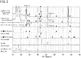
- the crystal structures of material C to be used in the negative electrode, material C in the negative electrode before initial charging, and material C in the negative electrode after 1 to 5 times of charging and discharging were determined by the following method. X-ray diffraction measurements were carried out for the target negative electrode active materials to obtain measured data. Then, based on the obtained measured data, crystal structures included in the target negative electrode active materials were determined by the Rietveld method. More specifically, the crystal structures were determined by the following method.
- X-ray diffraction measurements were carried out for the material C before use in the negative electrode to obtain measured data of X-ray diffraction profile.
- SmartLab product of Rigaku Co., Ltd
- rotor target maximum output 9KW 45kV-200mA
- the DO 3 ordered structure is an ordered structure as shown in FIG. 1 .
- a Cu-Sn base alloy mainly Cu is present at atomic sites shown by a black circle and mainly Sn is present at atomic sites shown by a white circle, in FIG. 1 . Respective sites may be replaced by addition of a third element. It is known that such a crystal structure falls into No. 225 (Fm-3m) of International Table (Volume-A) in the classification of space group representation. The lattice constant and atomic coordinates of this space group number are as shown in Table 2.
- a calculated value of diffraction profile (hereinafter, referred to as a calculated profile) of ⁇ 1 phase (DO 3 structure) of this chemical composition was found by Rietveld method.
- RIETAN-FP program name
- the crystal structure of a negative electrode active material in a negative electrode before charging was also determined by the same method as that in (1). Measured X-ray diffraction profiles were measured by the following method.
- the above described coin battery which was before being charged, was disassembled within the glove box in argon atmosphere, and a plate-shaped negative electrode (including nickel foil) was taken out from the coin battery.
- the negative electrode taken out was enclosed in Myler foil (manufactured by DuPont). Thereafter, the perimeter of the Myler foil was sealed by a thermocompression bonding machine. Then, the negative electrode sealed by the Myler foil was taken out of the glove box.
- a measurement sample was fabricated by bonding the negative electrode to a reflection-free sample plate manufactured by Rigaku Co., Ltd. (a plate of a silicon single crystal which was cut out such that a specific crystal plane was in parallel with the measurement plane) with a hair spray.
- the measurement sample was mounted onto the X-ray diffraction apparatus described below in (4), and the X-ray diffraction measurement of the measurement sample was performed under measurement conditions described below in (4).
- the crystal structure of the material C in the negative electrode active material in the negative electrode after one to 5 times of charging and after one to 5 times of discharging was also determined by the same method as that in (1). Measured X-ray diffraction profiles were measured by the following method.
- the above described coin battery was fully charged in a charging/discharging test apparatus.
- the fully charged coin battery was disassembled in the glove box, and a measurement sample was fabricated by the same method as that in (2).
- the measurement sample was mounted onto the X-ray diffraction apparatus described below in (4), and X-ray diffraction measurement of the measurement sample was performed under measurement conditions described below in (4).
- the above described coin battery was fully discharged.
- the fully discharged coin battery was disassembled in the glove box, and a measurement sample was fabricated by the same method as in (3).
- the measurement sample was mounted onto the X-ray diffraction apparatus described below in (4), and X-ray diffraction measurement of the measurement sample was performed at measurement conditions described below in (4).
- the X-ray diffraction data obtained in (2) and (3) are shown in FIG. 3 .
- the item (e) in FIG. 3 shows an X-ray diffraction profile of negative electrode plate obtained in (2).
- (f) is an X-ray diffraction profile of the negative electrode active material after first charging; and
- (g) is an X-ray diffraction profile after first discharging.
- Reference symbol (a) in FIG. 3 indicates a measured X-ray diffraction profile in which similar X-ray diffraction is performed on a Myler film alone.
- Reference symbol (b) in FIG. 3 indicates an X-ray diffraction profile of Ni, which is calculated to identify diffraction lines of Ni foil used for the current collector.
- Reference symbol (c) in FIG. 3 indicates a calculated profile of 2H structure in the chemical composition of the present example, and reference symbol (d) in FIG. 3 indicates a calculated profile of DO 3 structure in the chemical composition of the present example.
- the diffraction line repeatedly changed in a reversible manner at a position where the diffraction angle 2 ⁇ is near 43.5° (position caused by M phase ( ⁇ 1 ' phase))(hereinafter, referred to as a strongest diffraction line of M phase). That is, a structural change was suggested.
- the crystal structures of the "negative electrode active material after charging” and the “negative electrode active materials after discharging” were determined by using Rietveld method.
- the crystal plane A shown in FIG. 2D and the crystal plane B shown in FIG. 2C are alternately layered in the DO 3 structure of the matrix phase shown in FIGS. 1 and 2A .
- a phase transformation occurs between the DO 3 structure and ⁇ 1 ' phase which is a kind of M phase, as shown in FIGS. 2A and 2B , the crystal plane B regularly undergoes shuffling due to shear stress, thereby being displaced to the position of crystal plane B'.
- phase transformation M transformation
- the crystal plane A shown in FIG. 2D and the crystal plane B' shown in FIG. 2E are alternately layered.
- the intensity of the strongest diffraction line of M phase of near 43.5° increased as a result of initial charging, and decreased as a result of consecutive discharging. It can be judged that this diffraction line resulted from the formation of M phase ( ⁇ 1 ') by M transformation, as will be next described, from calculated profiles of RIETAN-FP).
- a measured diffraction profile of a Myler foil and a calculated profile of nickel of the current collector are shown by (a) and (b) in FIG. 3 respectively, in which 2 ⁇ angle positions of major diffraction lines are indicated by ⁇ (white rhombus) symbols and ⁇ (white triangle) symbols, respectively. Since diffraction lines resulted from these members appear in the measured profiles of (f) and (g) in FIG. 3 , corresponding positions are indicated by ⁇ (white rhombus) symbols and ⁇ (white triangle) symbols. Note that since the negative electrode active materials of Inventive Examples are each a composite material with graphite, diffraction lines resulted from graphite appeared, and as such is indicated in (e), (f), and (g) in FIG. 3 .
- the negative electrode of the present Example contained an alloy phase which underwent M transformation to become M phase (2H structure) as a result of charging, and became a matrix phase (DO 3 structure) as a result of discharging. That is, the negative electrode of the present Example contained an alloy phase which underwent M transformation when occluding lithium ions which are metal ions, and underwent reverse transformation when releasing lithium ions. In the negative electrode of the present Example, M transformation at the time of charging, and reverse transformation at the time of discharging were repeated.
- Constant current doping (corresponding to the insertion of lithium ions into electrode, and the charging of lithium ion secondary battery) was performed to a coin battery at a current value of 0.1 mA (a current value of 0.075 mA/cm 2 ) or a current value of 1.0 mA (a current value of 0.75 mA/cm 2 ) until the potential difference against the counter electrode becomes 0.005 V. Thereafter, doping capacity was measured by continuing doping against the counter electrode at a constant voltage until the current value became 7.5 ⁇ A/cm 2 while retaining 0.005 V.
- de-doping capacity was measured by performing de-doping (which corresponds to desorption of lithium ions from the electrode, and discharge of the lithium ion secondary battery) at a current value of 0.1 mA (a current value of 0.075 mA/cm 2 ) or a current value of 1.0 mA (a current value of 0.75 mA/cm 2 ) until the potential difference becomes 1.2 V.
- the doping capacity and de-doping capacity correspond to charge capacity and discharge capacity when the electrode is used as the negative electrode of the lithium ion secondary battery. Therefore, the measured dope capacity was defined as the charge capacity, and a measured de-doping capacity was defined as the discharge capacity.
- a capacity retention ratio (%) was defined as "the discharge capacity at the time of de-doping of the 20th cycle" divided by "the discharge capacity at the time of de-doping of the 1st cycle, and multiplied by 100.
- Comparative Example 2 a negative electrode active material, negative electrode, and coin battery were produced in the same way as in Inventive Example 1 excepting that only material C used in Inventive Example 1 was used as the negative electrode active substance.
- Inventive Example 7 a negative electrode active material, negative electrode, and coin battery were produced in the same way as in Inventive Example 1 excepting that the final chemical composition of the material C was changed to the composition according to Table 1.
- Comparative Example 3 a negative electrode active material, negative electrode, and coin battery were produced in the same way as in Inventive Example 1 excepting that only material C used in Inventive Example 7 was used as the negative electrode active substance.
- Inventive Example 8 the negative electrode active material, negative electrode, and coin battery were produced in the same way as in Inventive Example 1 excepting that the final chemical composition of the material C was changed to the composition listed in Table 1.
- Comparative Example 4 a negative electrode active material, negative electrode, and coin battery were produced in the same way as in Inventive Example 1 excepting that only material C used in Inventive Example 8 was used as the negative electrode active substance.
- the alloy phase changed as follows as charging/discharging was performed.
- the alloy phase was M phase (2H structure) before initial charging, M phase (2H structure) after initial charging, and a matrix phase (DO 3 structure) after initial discharging, and thereafter, the alloy phase underwent M transformation to be transformed into M phase (2H structure) through charging, and became matrix phase (DO 3 structure) through discharging.
- Comparative Example 1 the mass ratio of material A/material C was more than 7. For that reason, the discharge capacities at the initial and 20th cycles were less than 95 mAh/g.
- the negative electrode active materials of Comparative Examples 2 to 4 contained material C, they contained neither material A nor material B. As a result of that, all of the discharge capacities at the initial and 20th cycles, the capacity retention ratios, and the initial Coulomb efficiency were low.
Landscapes
- Chemical & Material Sciences (AREA)
- Chemical Kinetics & Catalysis (AREA)
- Electrochemistry (AREA)
- General Chemical & Material Sciences (AREA)
- Engineering & Computer Science (AREA)
- Composite Materials (AREA)
- Materials Engineering (AREA)
- Manufacturing & Machinery (AREA)
- Inorganic Chemistry (AREA)
- Mechanical Engineering (AREA)
- Metallurgy (AREA)
- Organic Chemistry (AREA)
- Battery Electrode And Active Subsutance (AREA)
- Manufacture Of Metal Powder And Suspensions Thereof (AREA)
- Powder Metallurgy (AREA)
Priority Applications (1)
| Application Number | Priority Date | Filing Date | Title |
|---|---|---|---|
| PL15754973T PL3113258T3 (pl) | 2014-02-25 | 2015-02-25 | Materiał substancji aktywnej elektrody ujemnej, elektroda ujemna, i ogniwo |
Applications Claiming Priority (2)
| Application Number | Priority Date | Filing Date | Title |
|---|---|---|---|
| JP2014034277 | 2014-02-25 | ||
| PCT/JP2015/000952 WO2015129265A1 (ja) | 2014-02-25 | 2015-02-25 | 負極活物質材料、負極及び電池 |
Publications (3)
| Publication Number | Publication Date |
|---|---|
| EP3113258A1 EP3113258A1 (en) | 2017-01-04 |
| EP3113258A4 EP3113258A4 (en) | 2017-07-19 |
| EP3113258B1 true EP3113258B1 (en) | 2019-04-03 |
Family
ID=54008599
Family Applications (1)
| Application Number | Title | Priority Date | Filing Date |
|---|---|---|---|
| EP15754973.4A Active EP3113258B1 (en) | 2014-02-25 | 2015-02-25 | Negative electrode active substance material, negative electrode, and cell |
Country Status (8)
| Country | Link |
|---|---|
| US (1) | US10128493B2 (ja) |
| EP (1) | EP3113258B1 (ja) |
| JP (2) | JP6350647B2 (ja) |
| KR (1) | KR101940386B1 (ja) |
| CN (1) | CN106030866B (ja) |
| HU (1) | HUE044657T2 (ja) |
| PL (1) | PL3113258T3 (ja) |
| WO (1) | WO2015129265A1 (ja) |
Families Citing this family (4)
| Publication number | Priority date | Publication date | Assignee | Title |
|---|---|---|---|---|
| US10381640B2 (en) * | 2012-08-27 | 2019-08-13 | Nippon Steel Corporation | Negative electrode active material |
| KR20190009331A (ko) * | 2016-05-18 | 2019-01-28 | 신닛테츠스미킨 카부시키카이샤 | 음극 활물질 재료, 음극 및 전지 |
| WO2017213147A1 (ja) * | 2016-06-10 | 2017-12-14 | 新日鐵住金株式会社 | 負極活物質材料、負極及び電池 |
| US11387449B2 (en) * | 2017-07-18 | 2022-07-12 | Nippon Steel Corporation | Negative electrode active material, negative electrode, and battery |
Family Cites Families (16)
| Publication number | Priority date | Publication date | Assignee | Title |
|---|---|---|---|---|
| JPH10308207A (ja) * | 1997-05-08 | 1998-11-17 | Matsushita Denchi Kogyo Kk | 非水電解液二次電池 |
| EP1043789B1 (en) * | 1998-10-22 | 2013-01-23 | Panasonic Corporation | Secondary cell having non-aqueous electrolyte |
| JP4056183B2 (ja) * | 1999-09-24 | 2008-03-05 | 松下電器産業株式会社 | 非水電解質二次電池用負極活物質および非水電解質二次電池 |
| JP4056180B2 (ja) * | 1999-08-30 | 2008-03-05 | 松下電器産業株式会社 | 非水電解質二次電池用負極活物質および非水電解質二次電池 |
| WO2001003210A1 (fr) * | 1999-07-01 | 2001-01-11 | Matsushita Electric Industrial Co., Ltd. | Pile secondaire a electrolyte non aqueux |
| JP4789330B2 (ja) * | 2001-02-22 | 2011-10-12 | 株式会社クレハ | 非水溶媒二次電池用電極材料、電極および二次電池 |
| JP4228593B2 (ja) * | 2002-05-29 | 2009-02-25 | ソニー株式会社 | 非水電解質二次電池 |
| JP3624417B2 (ja) * | 2002-08-07 | 2005-03-02 | ソニー株式会社 | 負極活物質及びその製造方法、並びに非水電解質電池 |
| JP2004087264A (ja) * | 2002-08-26 | 2004-03-18 | Mitsui Mining & Smelting Co Ltd | 非水電解液二次電池用負極材料及びその製造方法 |
| JP4366101B2 (ja) * | 2003-03-31 | 2009-11-18 | キヤノン株式会社 | リチウム二次電池 |
| JP5094013B2 (ja) | 2004-12-10 | 2012-12-12 | キヤノン株式会社 | リチウム二次電池用の電極構造体及び該電極構造体を有する二次電池 |
| JP2007128766A (ja) * | 2005-11-04 | 2007-05-24 | Sony Corp | 負極活物質および電池 |
| JP5143437B2 (ja) * | 2007-01-30 | 2013-02-13 | 日本カーボン株式会社 | リチウムイオン二次電池用負極活物質の製造方法、負極活物質及び負極 |
| KR100859687B1 (ko) | 2007-03-21 | 2008-09-23 | 삼성에스디아이 주식회사 | 리튬 이차 전지용 음극 활물질 및 그를 포함하는 리튬 이차전지 |
| KR101386163B1 (ko) | 2007-07-19 | 2014-04-17 | 삼성에스디아이 주식회사 | 복합 음극활물질, 이를 채용한 음극 및 리튬 전지 |
| US10381640B2 (en) * | 2012-08-27 | 2019-08-13 | Nippon Steel Corporation | Negative electrode active material |
-
2015
- 2015-02-25 EP EP15754973.4A patent/EP3113258B1/en active Active
- 2015-02-25 PL PL15754973T patent/PL3113258T3/pl unknown
- 2015-02-25 WO PCT/JP2015/000952 patent/WO2015129265A1/ja active Application Filing
- 2015-02-25 HU HUE15754973 patent/HUE044657T2/hu unknown
- 2015-02-25 JP JP2016505072A patent/JP6350647B2/ja active Active
- 2015-02-25 KR KR1020167026187A patent/KR101940386B1/ko active IP Right Grant
- 2015-02-25 CN CN201580009858.7A patent/CN106030866B/zh active Active
- 2015-02-25 US US15/115,920 patent/US10128493B2/en active Active
-
2018
- 2018-05-31 JP JP2018104192A patent/JP6737305B2/ja active Active
Non-Patent Citations (1)
| Title |
|---|
| None * |
Also Published As
| Publication number | Publication date |
|---|---|
| PL3113258T3 (pl) | 2019-08-30 |
| EP3113258A4 (en) | 2017-07-19 |
| US10128493B2 (en) | 2018-11-13 |
| JP6737305B2 (ja) | 2020-08-05 |
| EP3113258A1 (en) | 2017-01-04 |
| US20170170461A1 (en) | 2017-06-15 |
| KR20160124220A (ko) | 2016-10-26 |
| JP6350647B2 (ja) | 2018-07-04 |
| KR101940386B1 (ko) | 2019-04-11 |
| JPWO2015129265A1 (ja) | 2017-03-30 |
| CN106030866A (zh) | 2016-10-12 |
| HUE044657T2 (hu) | 2019-11-28 |
| JP2018200876A (ja) | 2018-12-20 |
| CN106030866B (zh) | 2020-06-02 |
| WO2015129265A1 (ja) | 2015-09-03 |
Similar Documents
| Publication | Publication Date | Title |
|---|---|---|
| US10381640B2 (en) | Negative electrode active material | |
| EP3113259B1 (en) | Negative electrode active substance material, negative electrode, and cell | |
| EP3113257B1 (en) | Negative electrode active substance material, negative electrode, and cell | |
| US10270087B2 (en) | Composite particle, negative electrode and battery | |
| JP6737305B2 (ja) | 負極活物質材料、負極及び電池 | |
| EP3113260B1 (en) | Negative electrode active substance material, negative electrode, and cell |
Legal Events
| Date | Code | Title | Description |
|---|---|---|---|
| PUAI | Public reference made under article 153(3) epc to a published international application that has entered the european phase |
Free format text: ORIGINAL CODE: 0009012 |
|
| STAA | Information on the status of an ep patent application or granted ep patent |
Free format text: STATUS: REQUEST FOR EXAMINATION WAS MADE |
|
| 17P | Request for examination filed |
Effective date: 20160810 |
|
| AK | Designated contracting states |
Kind code of ref document: A1 Designated state(s): AL AT BE BG CH CY CZ DE DK EE ES FI FR GB GR HR HU IE IS IT LI LT LU LV MC MK MT NL NO PL PT RO RS SE SI SK SM TR |
|
| AX | Request for extension of the european patent |
Extension state: BA ME |
|
| DAX | Request for extension of the european patent (deleted) | ||
| RIC1 | Information provided on ipc code assigned before grant |
Ipc: H01M 4/587 20100101ALI20170607BHEP Ipc: C22C 9/02 20060101ALI20170607BHEP Ipc: H01M 4/62 20060101ALI20170607BHEP Ipc: H01M 4/02 20060101ALI20170607BHEP Ipc: C22C 9/01 20060101ALI20170607BHEP Ipc: C22C 9/10 20060101ALI20170607BHEP Ipc: C22C 9/04 20060101ALI20170607BHEP Ipc: H01M 10/052 20100101ALI20170607BHEP Ipc: H01M 4/38 20060101AFI20170607BHEP Ipc: C22C 9/00 20060101ALI20170607BHEP Ipc: H01M 4/36 20060101ALI20170607BHEP Ipc: C22C 9/06 20060101ALI20170607BHEP |
|
| A4 | Supplementary search report drawn up and despatched |
Effective date: 20170619 |
|
| STAA | Information on the status of an ep patent application or granted ep patent |
Free format text: STATUS: EXAMINATION IS IN PROGRESS |
|
| 17Q | First examination report despatched |
Effective date: 20180424 |
|
| GRAP | Despatch of communication of intention to grant a patent |
Free format text: ORIGINAL CODE: EPIDOSNIGR1 |
|
| STAA | Information on the status of an ep patent application or granted ep patent |
Free format text: STATUS: GRANT OF PATENT IS INTENDED |
|
| INTG | Intention to grant announced |
Effective date: 20181105 |
|
| GRAS | Grant fee paid |
Free format text: ORIGINAL CODE: EPIDOSNIGR3 |
|
| GRAA | (expected) grant |
Free format text: ORIGINAL CODE: 0009210 |
|
| STAA | Information on the status of an ep patent application or granted ep patent |
Free format text: STATUS: THE PATENT HAS BEEN GRANTED |
|
| AK | Designated contracting states |
Kind code of ref document: B1 Designated state(s): AL AT BE BG CH CY CZ DE DK EE ES FI FR GB GR HR HU IE IS IT LI LT LU LV MC MK MT NL NO PL PT RO RS SE SI SK SM TR |
|
| REG | Reference to a national code |
Ref country code: GB Ref legal event code: FG4D |
|
| REG | Reference to a national code |
Ref country code: AT Ref legal event code: REF Ref document number: 1116855 Country of ref document: AT Kind code of ref document: T Effective date: 20190415 Ref country code: CH Ref legal event code: EP |
|
| REG | Reference to a national code |
Ref country code: DE Ref legal event code: R096 Ref document number: 602015027624 Country of ref document: DE |
|
| REG | Reference to a national code |
Ref country code: IE Ref legal event code: FG4D |
|
| RAP2 | Party data changed (patent owner data changed or rights of a patent transferred) |
Owner name: NIPPON STEEL CORPORATION |
|
| REG | Reference to a national code |
Ref country code: NL Ref legal event code: MP Effective date: 20190403 |
|
| REG | Reference to a national code |
Ref country code: LT Ref legal event code: MG4D |
|
| REG | Reference to a national code |
Ref country code: AT Ref legal event code: MK05 Ref document number: 1116855 Country of ref document: AT Kind code of ref document: T Effective date: 20190403 |
|
| PG25 | Lapsed in a contracting state [announced via postgrant information from national office to epo] |
Ref country code: NL Free format text: LAPSE BECAUSE OF FAILURE TO SUBMIT A TRANSLATION OF THE DESCRIPTION OR TO PAY THE FEE WITHIN THE PRESCRIBED TIME-LIMIT Effective date: 20190403 |
|
| PG25 | Lapsed in a contracting state [announced via postgrant information from national office to epo] |
Ref country code: ES Free format text: LAPSE BECAUSE OF FAILURE TO SUBMIT A TRANSLATION OF THE DESCRIPTION OR TO PAY THE FEE WITHIN THE PRESCRIBED TIME-LIMIT Effective date: 20190403 Ref country code: LT Free format text: LAPSE BECAUSE OF FAILURE TO SUBMIT A TRANSLATION OF THE DESCRIPTION OR TO PAY THE FEE WITHIN THE PRESCRIBED TIME-LIMIT Effective date: 20190403 Ref country code: CZ Free format text: LAPSE BECAUSE OF FAILURE TO SUBMIT A TRANSLATION OF THE DESCRIPTION OR TO PAY THE FEE WITHIN THE PRESCRIBED TIME-LIMIT Effective date: 20190403 Ref country code: PT Free format text: LAPSE BECAUSE OF FAILURE TO SUBMIT A TRANSLATION OF THE DESCRIPTION OR TO PAY THE FEE WITHIN THE PRESCRIBED TIME-LIMIT Effective date: 20190803 Ref country code: AL Free format text: LAPSE BECAUSE OF FAILURE TO SUBMIT A TRANSLATION OF THE DESCRIPTION OR TO PAY THE FEE WITHIN THE PRESCRIBED TIME-LIMIT Effective date: 20190403 Ref country code: FI Free format text: LAPSE BECAUSE OF FAILURE TO SUBMIT A TRANSLATION OF THE DESCRIPTION OR TO PAY THE FEE WITHIN THE PRESCRIBED TIME-LIMIT Effective date: 20190403 Ref country code: SE Free format text: LAPSE BECAUSE OF FAILURE TO SUBMIT A TRANSLATION OF THE DESCRIPTION OR TO PAY THE FEE WITHIN THE PRESCRIBED TIME-LIMIT Effective date: 20190403 Ref country code: NO Free format text: LAPSE BECAUSE OF FAILURE TO SUBMIT A TRANSLATION OF THE DESCRIPTION OR TO PAY THE FEE WITHIN THE PRESCRIBED TIME-LIMIT Effective date: 20190703 Ref country code: HR Free format text: LAPSE BECAUSE OF FAILURE TO SUBMIT A TRANSLATION OF THE DESCRIPTION OR TO PAY THE FEE WITHIN THE PRESCRIBED TIME-LIMIT Effective date: 20190403 |
|
| REG | Reference to a national code |
Ref country code: DE Ref legal event code: R081 Ref document number: 602015027624 Country of ref document: DE Owner name: NIPPON STEEL CORPORATION, JP Free format text: FORMER OWNER: NIPPON STEEL & SUMITOMO METAL CORPORATION, TOKYO, JP |
|
| REG | Reference to a national code |
Ref country code: HU Ref legal event code: AG4A Ref document number: E044657 Country of ref document: HU |
|
| PG25 | Lapsed in a contracting state [announced via postgrant information from national office to epo] |
Ref country code: LV Free format text: LAPSE BECAUSE OF FAILURE TO SUBMIT A TRANSLATION OF THE DESCRIPTION OR TO PAY THE FEE WITHIN THE PRESCRIBED TIME-LIMIT Effective date: 20190403 Ref country code: GR Free format text: LAPSE BECAUSE OF FAILURE TO SUBMIT A TRANSLATION OF THE DESCRIPTION OR TO PAY THE FEE WITHIN THE PRESCRIBED TIME-LIMIT Effective date: 20190704 Ref country code: RS Free format text: LAPSE BECAUSE OF FAILURE TO SUBMIT A TRANSLATION OF THE DESCRIPTION OR TO PAY THE FEE WITHIN THE PRESCRIBED TIME-LIMIT Effective date: 20190403 Ref country code: BG Free format text: LAPSE BECAUSE OF FAILURE TO SUBMIT A TRANSLATION OF THE DESCRIPTION OR TO PAY THE FEE WITHIN THE PRESCRIBED TIME-LIMIT Effective date: 20190703 |
|
| PG25 | Lapsed in a contracting state [announced via postgrant information from national office to epo] |
Ref country code: IS Free format text: LAPSE BECAUSE OF FAILURE TO SUBMIT A TRANSLATION OF THE DESCRIPTION OR TO PAY THE FEE WITHIN THE PRESCRIBED TIME-LIMIT Effective date: 20190803 Ref country code: AT Free format text: LAPSE BECAUSE OF FAILURE TO SUBMIT A TRANSLATION OF THE DESCRIPTION OR TO PAY THE FEE WITHIN THE PRESCRIBED TIME-LIMIT Effective date: 20190403 |
|
| REG | Reference to a national code |
Ref country code: DE Ref legal event code: R097 Ref document number: 602015027624 Country of ref document: DE |
|
| PG25 | Lapsed in a contracting state [announced via postgrant information from national office to epo] |
Ref country code: EE Free format text: LAPSE BECAUSE OF FAILURE TO SUBMIT A TRANSLATION OF THE DESCRIPTION OR TO PAY THE FEE WITHIN THE PRESCRIBED TIME-LIMIT Effective date: 20190403 Ref country code: DK Free format text: LAPSE BECAUSE OF FAILURE TO SUBMIT A TRANSLATION OF THE DESCRIPTION OR TO PAY THE FEE WITHIN THE PRESCRIBED TIME-LIMIT Effective date: 20190403 Ref country code: RO Free format text: LAPSE BECAUSE OF FAILURE TO SUBMIT A TRANSLATION OF THE DESCRIPTION OR TO PAY THE FEE WITHIN THE PRESCRIBED TIME-LIMIT Effective date: 20190403 Ref country code: SK Free format text: LAPSE BECAUSE OF FAILURE TO SUBMIT A TRANSLATION OF THE DESCRIPTION OR TO PAY THE FEE WITHIN THE PRESCRIBED TIME-LIMIT Effective date: 20190403 |
|
| PLBE | No opposition filed within time limit |
Free format text: ORIGINAL CODE: 0009261 |
|
| STAA | Information on the status of an ep patent application or granted ep patent |
Free format text: STATUS: NO OPPOSITION FILED WITHIN TIME LIMIT |
|
| PG25 | Lapsed in a contracting state [announced via postgrant information from national office to epo] |
Ref country code: SM Free format text: LAPSE BECAUSE OF FAILURE TO SUBMIT A TRANSLATION OF THE DESCRIPTION OR TO PAY THE FEE WITHIN THE PRESCRIBED TIME-LIMIT Effective date: 20190403 |
|
| 26N | No opposition filed |
Effective date: 20200106 |
|
| PG25 | Lapsed in a contracting state [announced via postgrant information from national office to epo] |
Ref country code: TR Free format text: LAPSE BECAUSE OF FAILURE TO SUBMIT A TRANSLATION OF THE DESCRIPTION OR TO PAY THE FEE WITHIN THE PRESCRIBED TIME-LIMIT Effective date: 20190403 |
|
| PGFP | Annual fee paid to national office [announced via postgrant information from national office to epo] |
Ref country code: IT Payment date: 20200225 Year of fee payment: 6 Ref country code: GB Payment date: 20200219 Year of fee payment: 6 |
|
| PG25 | Lapsed in a contracting state [announced via postgrant information from national office to epo] |
Ref country code: SI Free format text: LAPSE BECAUSE OF FAILURE TO SUBMIT A TRANSLATION OF THE DESCRIPTION OR TO PAY THE FEE WITHIN THE PRESCRIBED TIME-LIMIT Effective date: 20190403 |
|
| REG | Reference to a national code |
Ref country code: CH Ref legal event code: PL |
|
| REG | Reference to a national code |
Ref country code: BE Ref legal event code: MM Effective date: 20200229 |
|
| PG25 | Lapsed in a contracting state [announced via postgrant information from national office to epo] |
Ref country code: LU Free format text: LAPSE BECAUSE OF NON-PAYMENT OF DUE FEES Effective date: 20200225 Ref country code: MC Free format text: LAPSE BECAUSE OF FAILURE TO SUBMIT A TRANSLATION OF THE DESCRIPTION OR TO PAY THE FEE WITHIN THE PRESCRIBED TIME-LIMIT Effective date: 20190403 |
|
| PG25 | Lapsed in a contracting state [announced via postgrant information from national office to epo] |
Ref country code: LI Free format text: LAPSE BECAUSE OF NON-PAYMENT OF DUE FEES Effective date: 20200229 Ref country code: CH Free format text: LAPSE BECAUSE OF NON-PAYMENT OF DUE FEES Effective date: 20200229 |
|
| PG25 | Lapsed in a contracting state [announced via postgrant information from national office to epo] |
Ref country code: IE Free format text: LAPSE BECAUSE OF NON-PAYMENT OF DUE FEES Effective date: 20200225 |
|
| PG25 | Lapsed in a contracting state [announced via postgrant information from national office to epo] |
Ref country code: BE Free format text: LAPSE BECAUSE OF NON-PAYMENT OF DUE FEES Effective date: 20200229 |
|
| GBPC | Gb: european patent ceased through non-payment of renewal fee |
Effective date: 20210225 |
|
| PG25 | Lapsed in a contracting state [announced via postgrant information from national office to epo] |
Ref country code: GB Free format text: LAPSE BECAUSE OF NON-PAYMENT OF DUE FEES Effective date: 20210225 |
|
| PG25 | Lapsed in a contracting state [announced via postgrant information from national office to epo] |
Ref country code: IT Free format text: LAPSE BECAUSE OF NON-PAYMENT OF DUE FEES Effective date: 20210225 |
|
| PG25 | Lapsed in a contracting state [announced via postgrant information from national office to epo] |
Ref country code: MT Free format text: LAPSE BECAUSE OF FAILURE TO SUBMIT A TRANSLATION OF THE DESCRIPTION OR TO PAY THE FEE WITHIN THE PRESCRIBED TIME-LIMIT Effective date: 20190403 Ref country code: CY Free format text: LAPSE BECAUSE OF FAILURE TO SUBMIT A TRANSLATION OF THE DESCRIPTION OR TO PAY THE FEE WITHIN THE PRESCRIBED TIME-LIMIT Effective date: 20190403 |
|
| PG25 | Lapsed in a contracting state [announced via postgrant information from national office to epo] |
Ref country code: MK Free format text: LAPSE BECAUSE OF FAILURE TO SUBMIT A TRANSLATION OF THE DESCRIPTION OR TO PAY THE FEE WITHIN THE PRESCRIBED TIME-LIMIT Effective date: 20190403 |
|
| PGFP | Annual fee paid to national office [announced via postgrant information from national office to epo] |
Ref country code: HU Payment date: 20240222 Year of fee payment: 10 Ref country code: DE Payment date: 20240219 Year of fee payment: 10 |
|
| PGFP | Annual fee paid to national office [announced via postgrant information from national office to epo] |
Ref country code: PL Payment date: 20240201 Year of fee payment: 10 Ref country code: FR Payment date: 20240221 Year of fee payment: 10 |