EP3112544A1 - Akustikpaneel - Google Patents
Akustikpaneel Download PDFInfo
- Publication number
- EP3112544A1 EP3112544A1 EP15174338.2A EP15174338A EP3112544A1 EP 3112544 A1 EP3112544 A1 EP 3112544A1 EP 15174338 A EP15174338 A EP 15174338A EP 3112544 A1 EP3112544 A1 EP 3112544A1
- Authority
- EP
- European Patent Office
- Prior art keywords
- layer
- acoustic panel
- acoustic
- panel
- base plate
- Prior art date
- Legal status (The legal status is an assumption and is not a legal conclusion. Google has not performed a legal analysis and makes no representation as to the accuracy of the status listed.)
- Granted
Links
Images


Classifications
-
- E—FIXED CONSTRUCTIONS
- E04—BUILDING
- E04B—GENERAL BUILDING CONSTRUCTIONS; WALLS, e.g. PARTITIONS; ROOFS; FLOORS; CEILINGS; INSULATION OR OTHER PROTECTION OF BUILDINGS
- E04B1/00—Constructions in general; Structures which are not restricted either to walls, e.g. partitions, or floors or ceilings or roofs
- E04B1/62—Insulation or other protection; Elements or use of specified material therefor
- E04B1/74—Heat, sound or noise insulation, absorption, or reflection; Other building methods affording favourable thermal or acoustical conditions, e.g. accumulating of heat within walls
- E04B1/82—Heat, sound or noise insulation, absorption, or reflection; Other building methods affording favourable thermal or acoustical conditions, e.g. accumulating of heat within walls specifically with respect to sound only
- E04B1/84—Sound-absorbing elements
- E04B1/86—Sound-absorbing elements slab-shaped
-
- E—FIXED CONSTRUCTIONS
- E04—BUILDING
- E04F—FINISHING WORK ON BUILDINGS, e.g. STAIRS, FLOORS
- E04F13/00—Coverings or linings, e.g. for walls or ceilings
- E04F13/07—Coverings or linings, e.g. for walls or ceilings composed of covering or lining elements; Sub-structures therefor; Fastening means therefor
- E04F13/08—Coverings or linings, e.g. for walls or ceilings composed of covering or lining elements; Sub-structures therefor; Fastening means therefor composed of a plurality of similar covering or lining elements
- E04F13/0801—Separate fastening elements
- E04F13/0803—Separate fastening elements with load-supporting elongated furring elements between wall and covering elements
- E04F13/081—Separate fastening elements with load-supporting elongated furring elements between wall and covering elements with additional fastening elements between furring elements and covering elements
- E04F13/0821—Separate fastening elements with load-supporting elongated furring elements between wall and covering elements with additional fastening elements between furring elements and covering elements the additional fastening elements located in-between two adjacent covering elements
- E04F13/0826—Separate fastening elements with load-supporting elongated furring elements between wall and covering elements with additional fastening elements between furring elements and covering elements the additional fastening elements located in-between two adjacent covering elements engaging side grooves running along the whole length of the covering elements
-
- E—FIXED CONSTRUCTIONS
- E04—BUILDING
- E04F—FINISHING WORK ON BUILDINGS, e.g. STAIRS, FLOORS
- E04F13/00—Coverings or linings, e.g. for walls or ceilings
- E04F13/07—Coverings or linings, e.g. for walls or ceilings composed of covering or lining elements; Sub-structures therefor; Fastening means therefor
- E04F13/08—Coverings or linings, e.g. for walls or ceilings composed of covering or lining elements; Sub-structures therefor; Fastening means therefor composed of a plurality of similar covering or lining elements
- E04F13/0866—Coverings or linings, e.g. for walls or ceilings composed of covering or lining elements; Sub-structures therefor; Fastening means therefor composed of a plurality of similar covering or lining elements composed of several layers, e.g. sandwich panels or layered panels
-
- E—FIXED CONSTRUCTIONS
- E04—BUILDING
- E04F—FINISHING WORK ON BUILDINGS, e.g. STAIRS, FLOORS
- E04F13/00—Coverings or linings, e.g. for walls or ceilings
- E04F13/07—Coverings or linings, e.g. for walls or ceilings composed of covering or lining elements; Sub-structures therefor; Fastening means therefor
- E04F13/08—Coverings or linings, e.g. for walls or ceilings composed of covering or lining elements; Sub-structures therefor; Fastening means therefor composed of a plurality of similar covering or lining elements
- E04F13/0889—Coverings or linings, e.g. for walls or ceilings composed of covering or lining elements; Sub-structures therefor; Fastening means therefor composed of a plurality of similar covering or lining elements characterised by the joints between neighbouring elements, e.g. with joint fillings or with tongue and groove connections
- E04F13/0894—Coverings or linings, e.g. for walls or ceilings composed of covering or lining elements; Sub-structures therefor; Fastening means therefor composed of a plurality of similar covering or lining elements characterised by the joints between neighbouring elements, e.g. with joint fillings or with tongue and groove connections with tongue and groove connections
-
- E—FIXED CONSTRUCTIONS
- E04—BUILDING
- E04F—FINISHING WORK ON BUILDINGS, e.g. STAIRS, FLOORS
- E04F13/00—Coverings or linings, e.g. for walls or ceilings
- E04F13/07—Coverings or linings, e.g. for walls or ceilings composed of covering or lining elements; Sub-structures therefor; Fastening means therefor
- E04F13/08—Coverings or linings, e.g. for walls or ceilings composed of covering or lining elements; Sub-structures therefor; Fastening means therefor composed of a plurality of similar covering or lining elements
- E04F13/10—Coverings or linings, e.g. for walls or ceilings composed of covering or lining elements; Sub-structures therefor; Fastening means therefor composed of a plurality of similar covering or lining elements of wood or with an outer layer of wood
-
- E—FIXED CONSTRUCTIONS
- E04—BUILDING
- E04B—GENERAL BUILDING CONSTRUCTIONS; WALLS, e.g. PARTITIONS; ROOFS; FLOORS; CEILINGS; INSULATION OR OTHER PROTECTION OF BUILDINGS
- E04B1/00—Constructions in general; Structures which are not restricted either to walls, e.g. partitions, or floors or ceilings or roofs
- E04B1/62—Insulation or other protection; Elements or use of specified material therefor
- E04B1/74—Heat, sound or noise insulation, absorption, or reflection; Other building methods affording favourable thermal or acoustical conditions, e.g. accumulating of heat within walls
- E04B1/82—Heat, sound or noise insulation, absorption, or reflection; Other building methods affording favourable thermal or acoustical conditions, e.g. accumulating of heat within walls specifically with respect to sound only
- E04B1/84—Sound-absorbing elements
- E04B2001/8457—Solid slabs or blocks
- E04B2001/8461—Solid slabs or blocks layered
-
- E—FIXED CONSTRUCTIONS
- E04—BUILDING
- E04B—GENERAL BUILDING CONSTRUCTIONS; WALLS, e.g. PARTITIONS; ROOFS; FLOORS; CEILINGS; INSULATION OR OTHER PROTECTION OF BUILDINGS
- E04B1/00—Constructions in general; Structures which are not restricted either to walls, e.g. partitions, or floors or ceilings or roofs
- E04B1/62—Insulation or other protection; Elements or use of specified material therefor
- E04B1/74—Heat, sound or noise insulation, absorption, or reflection; Other building methods affording favourable thermal or acoustical conditions, e.g. accumulating of heat within walls
- E04B1/82—Heat, sound or noise insulation, absorption, or reflection; Other building methods affording favourable thermal or acoustical conditions, e.g. accumulating of heat within walls specifically with respect to sound only
- E04B1/84—Sound-absorbing elements
- E04B2001/8457—Solid slabs or blocks
- E04B2001/8476—Solid slabs or blocks with acoustical cavities, with or without acoustical filling
- E04B2001/848—Solid slabs or blocks with acoustical cavities, with or without acoustical filling the cavities opening onto the face of the element
- E04B2001/849—Groove or slot type openings
-
- E—FIXED CONSTRUCTIONS
- E04—BUILDING
- E04F—FINISHING WORK ON BUILDINGS, e.g. STAIRS, FLOORS
- E04F13/00—Coverings or linings, e.g. for walls or ceilings
- E04F13/07—Coverings or linings, e.g. for walls or ceilings composed of covering or lining elements; Sub-structures therefor; Fastening means therefor
- E04F13/08—Coverings or linings, e.g. for walls or ceilings composed of covering or lining elements; Sub-structures therefor; Fastening means therefor composed of a plurality of similar covering or lining elements
- E04F13/088—Coverings or linings, e.g. for walls or ceilings composed of covering or lining elements; Sub-structures therefor; Fastening means therefor composed of a plurality of similar covering or lining elements fixed directly to the wall by means of magnets, hook and loop-type or similar fasteners, not necessarily involving the side faces of the covering element
- E04F13/0883—Coverings or linings, e.g. for walls or ceilings composed of covering or lining elements; Sub-structures therefor; Fastening means therefor composed of a plurality of similar covering or lining elements fixed directly to the wall by means of magnets, hook and loop-type or similar fasteners, not necessarily involving the side faces of the covering element by magnets
-
- E—FIXED CONSTRUCTIONS
- E04—BUILDING
- E04F—FINISHING WORK ON BUILDINGS, e.g. STAIRS, FLOORS
- E04F2201/00—Joining sheets or plates or panels
- E04F2201/01—Joining sheets, plates or panels with edges in abutting relationship
- E04F2201/0138—Joining sheets, plates or panels with edges in abutting relationship by moving the sheets, plates or panels perpendicular to the main plane
-
- E—FIXED CONSTRUCTIONS
- E04—BUILDING
- E04F—FINISHING WORK ON BUILDINGS, e.g. STAIRS, FLOORS
- E04F2201/00—Joining sheets or plates or panels
- E04F2201/01—Joining sheets, plates or panels with edges in abutting relationship
- E04F2201/0153—Joining sheets, plates or panels with edges in abutting relationship by rotating the sheets, plates or panels around an axis which is parallel to the abutting edges, possibly combined with a sliding movement
-
- E—FIXED CONSTRUCTIONS
- E04—BUILDING
- E04F—FINISHING WORK ON BUILDINGS, e.g. STAIRS, FLOORS
- E04F2290/00—Specially adapted covering, lining or flooring elements not otherwise provided for
- E04F2290/04—Specially adapted covering, lining or flooring elements not otherwise provided for for insulation or surface protection, e.g. against noise, impact or fire
- E04F2290/041—Specially adapted covering, lining or flooring elements not otherwise provided for for insulation or surface protection, e.g. against noise, impact or fire against noise
- E04F2290/042—Specially adapted covering, lining or flooring elements not otherwise provided for for insulation or surface protection, e.g. against noise, impact or fire against noise with a facing or top layer for sound insulation
Definitions
- the invention relates to an acoustic panel according to the preamble of independent claim 1 and to a method for producing an acoustic panel according to the preamble of independent claim 11.
- Acoustic elements for use as a wall or ceiling covering are used to influence the room acoustics.
- the room acoustics are influenced by sound waves radiated directly from a sound source and sound waves reflected by walls, ceilings and furnishings that occur in a room.
- Decisive for the improvement of the room acoustics is the reduction of the direct sound reflection in the room.
- the degree of sound absorption of the respective materials serves as a measure of this.
- Acoustic elements are intended in particular for use in meeting rooms, entrance areas, restaurants, offices, concert halls, meeting rooms, schools or sports facilities.
- Such an acoustic element is, for example, from the DE 10 2014 207 852 A1 discloses a panel with a Holzmaschinedämmplatte, a wood-based panel and a resting on the wood-based panel visible solid wood surface, wherein in the solid wood surface and the wood-based panel slits are incorporated into the wood fiber insulation.
- a NutfederNK is provided in the wood-based panel.
- Further acoustic elements are, for example, from the DE 20 2009 016 944 U1 , of the EP 2 216 773 B1 and the WO 2006/056351 A1 known.
- Known acoustic panels have a multilayer structure and have a viewing surface directed towards the room and provided with perforations or other recesses, which is designed so that the sound waves penetrate through them into an absorber surface and run there.
- the structural design of the known panels is designed to achieve a high efficiency particularly expensive.
- Each panel is designed as an independent component and provided for each separate attachment to the wall or ceiling.
- the production of visually appealing, acoustically particularly effective and precisely mountable acoustic panels, ie acoustic panels can be produced by means of mountable without offset covering surfaces is complicated and costly with the known acoustic panels and manufacturing processes.
- the invention is therefore an object of the invention to provide a structurally particularly simple and inexpensive to manufacture acoustic panel can be formed with the offsetless and visually appealing surfaces. It is also an object to provide a corresponding method for producing such an acoustic panel.
- the invention achieves the object by an acoustic panel having the features of claim 1 and a method having the features of claim 11.
- Advantageous developments of the invention are specified in the dependent claims. In this case, the features described in themselves or in any combination in principle subject of the invention, regardless of their summary in the claims or their dependency.
- the acoustic panel according to the invention for use as ceiling and / or wall covering has a base plate which comprises at least one wood-based panel having a top and a bottom and a top layer arranged on the top and on the longitudinal sides and / or end sides mutually corresponding locking profiles for adhesive-free bonding having further acoustic panels and an absorber unit arranged on the underside for absorbing room sound and a multiplicity of recesses which pass completely through the baseplate and allow the passage of space sound impinging on the upper side into the absorber unit.
- the design of the acoustic panel with corresponding locking profiles makes it possible in a particularly simple manner to produce wall and ceiling coverings with non-offset surfaces, since the locking profiles guarantee an offsetless connection of the acoustic panels. Even in the case of unevenness on the direct wall or ceiling surface, or in the fastening means for the acoustic panels, the surface visible in the space produced by the acoustic panels is without offset. Due to the Verrieglungsprofile is also ensured that the surface remains permanently offset and the positioning of the individual panels to each other permanently consistent, so that, for example, even in setting activities of the building and / or climate-induced changes in individual building materials, such as the wood-based panel, the surface of the coating produced remains permanently consistent. By offset is meant that the panel surfaces are arranged in a plane.
- the acoustic panel according to the invention can be produced by a method matched to the acoustic panel, which method is particularly cost-effective, since individual method steps are at least partially known from the production of floor, wall or ceiling laminates.
- a further particular advantage of the inventive acoustic panel is that, alternatively, a floor, wall or ceiling laminate known per se and cost-effective to produce can be further processed into an inventive acoustic panel in a particularly cost-effective manner by modification with the corresponding recesses and connection to a lower-side absorber unit can.
- the particularly simple structural design of the inventive acoustic panel thus makes it possible to modify any known as wall, ceiling or floor laminate panel in a simple and cost-effective manner to the acoustic panel.
- Under ceiling and wall coverings are from the interior of visible coatings (cladding, coverings) on the walls and ceilings to understand. These can either be directly connected to the wall or the ceiling or arranged on a fastening device and corresponding connection means such as. Over drop or suspended ceilings, clip systems, and rail systems with mounting claws on these.
- the wood-based panel may in particular be a chipboard or fiberboard, for example an MDF or HDF board, or a mineral fiber-bonded board.
- the wood-based panel is depending on the intended application in particular as formaldehydarm or formaldehyde-free glued wood-based panel with a Formaldehydausticianskonzentration of ⁇ 0.02 ppm, according to EN 717-1 formed.
- the chipboards or fiberboards preferably used for the inventive acoustic panel may contain at least in large part isocyanate as a binder.
- the wood-based panels may contain other additives, such as, for example, fire retardants.
- the base plate can also comprise a chipboard or a fiber board, for example an MDF or HDF board.
- a base plate also has at least largely the later panel length and panel width and may have on the top next to at least one cover layer, for example.
- a decorative layer further coating layers.
- the base plate may also have on the underside a coating of one or more layers, for example a bottom-side undercoat coating.
- the base plate is preferably between 4 mm and 12 mm thick with coatings.
- a panel for example an acoustic panel
- a base plate with mutually corresponding locking profiles on the front and / or longitudinal sides of the base plate.
- the locking profiles of the panel are designed for adhesive-free connection of several panels with each other.
- the profiles arranged on the longitudinal sides and the profiles arranged on the transverse sides (end faces) can correspond to each other, so that a completely flat (offset) surface (wall or ceiling covering) can be formed by means of a plurality of acoustic panels.
- the cover layer can be designed in particular as a decorative layer.
- the decorative layer may be formed in particular monochrome or show a wood decor, a stone surface, a tile decor or fantasy decoration.
- the cover layer may, for example, be formed as a wear layer.
- the cover layer can also be multi-layered.
- An optionally arranged on the underside of the coating may, for example, be designed as a counter-pull and comprise one or more layers.
- the coating can be arranged adjacent to the absorber unit or connected to the absorber unit.
- the layer acting as a countermovement can be, for example, in the formation of the decorative layer by means of a decorative paper a Gegenzugpapier.
- a lacquer layer which acts in response to the decorative layer.
- the lower side of the cover layer is consequently opposite Understood surface of the wood-based panel, the base plate or the panel / acoustic panel, which may be uncoated or coated according to the context (for example, with a Martinezzug Mrs).
- the underside can alternatively also be coated with one or more cover layers, for example a decorative layer.
- An absorber unit is understood to mean a structure which is designed to accommodate the sound waves and in which the sound waves are dispersed.
- Absorber units have, in particular, a particularly low density in the range from 50 kg / m 3 to 300 kg / m 3 and are preferably open-pored.
- Absorber units can, for example, consist of plastics.
- the absorber units are made of wood material, for example. From a Holzfaserdämmplatte formed.
- the absorber unit is in particular plate-shaped and connected in a flat manner to the wood-based material board or its coating.
- the recesses in the base plate may have different geometric shapes. You can, for example, be designed as round or square holes or slot-shaped.
- the recesses are arranged side by side in the longitudinal and / or transverse direction of the panel.
- the recesses completely pass through the base plate, i.e., the recesses, in addition to the wood-based panel, also penetrate all layers of the coating, i. Both the cover layer or other layers on the top, as well as all applied to the bottom layers, such as a Gegenzug harsh.
- the recesses are thus designed so that sound waves impinging on the coating on the upper side are conducted through the recesses, strike the absorber unit, penetrate into it and dissipate in it.
- decor recesses may be arranged which protrude through the cover layer into the wood-based panel, but they do not penetrate.
- the decorative recesses ensure a particularly high stability of the acoustic panel in the edge region and thus a particularly secure and durable connection of several acoustic panels together by means of the binder-free locking profiles.
- the absorber unit can directly in the production of the base plate, for example. With the help of a arranged on the bottom adhesive counter-pull, are connected to the wood-based panel. According to a development of the invention, however, an additional adhesive layer for connecting the absorber unit to the underside is arranged between the underside (ie, the surface of the wood-based panel or the optionally present coating) and the absorber unit.
- This may in particular be a hot melt adhesive (hot melt), an adhesive film or a one-component adhesive, such as white glue.
- the recesses pass through the adhesive layer. That is, the recesses project through the adhesive layer.
- a significant improvement in the sound absorption is achieved because the penetrating into the recesses sound waves can penetrate particularly easily in the absorber unit and are not reflected by the adhesive layer.
- the recesses extend into the absorber unit.
- the recesses project beyond the underside of the panel and an optionally arranged adhesive layer into the absorber unit, so that recesses are likewise arranged in the absorber unit.
- the recesses do not penetrate the absorber unit.
- the recesses extending into the absorber unit significantly improve the sound absorption.
- the recesses passing through the panel and optionally also the decorative recesses extend over the entire length of the acoustic panel, whereby a further improved sound absorption of the sound impinging on the panel is made possible.
- reinforcing elements aligned with the underside in particular transversely to the longitudinal direction of the wood-based material board or base plate or transversely to a longitudinal direction of the recesses, are arranged.
- the reinforcing elements can, for example, be designed as strips (rod-shaped).
- the reinforcing elements are connected to the underside, in particular adhesively bonded, and ensure increased strength of the panel, for example with a high number of recesses penetrating the panel.
- the reinforcing elements are particularly adapted to the material of the wood-based panel and thus preferably consist of wood-based material, such as chipboard, HDF or MDF.
- the reinforcing elements are preferably arranged at a distance from one another, wherein, for example, in the region of the end faces, in particular adjacent to the end-side locking profiles, in each case one arranged in the transverse direction of the panel reinforcing element is arranged.
- the reinforcing elements are preferably between 10 mm - 50 mm, in particular 20 mm +/- 2 mm wide.
- the reinforcing elements are adapted in their thickness to the thickness of the absorber unit.
- the thickness of the reinforcing element is equal to the thickness of the absorber unit or up to 20% lower than the absorber unit, whereby a secure compression of reinforcing element and absorber element is ensured with the bottom.
- the absorber unit adapted to the height of the base plate, formed between 4 mm to 14 mm high.
- the particularly preferred dimensions ensure an optimal ratio of high stability, low production costs, minimum thickness and high sound absorption rates. Particularly good sound absorption rates are also achieved from a height ratio of about 1: 1 between the base plate and absorber unit.
- the absorber unit is preferably in one piece, designed and covers the underside of the wood-based panel as far as possible (possibly up to edge areas) completely.
- the absorber unit particularly preferably has a plurality of absorber elements, which are arranged in particular between the reinforcing elements.
- a high sound absorption is achieved in accordance with sufficiently high strength of the acoustic panel.
- the particularly thin construction of the acoustic panel makes it possible to retrofit rooms in which no acoustic panels were provided during the construction planning, without retrofitting substantial space losses with acoustic panels.
- the top layer arranged on the top layer may be formed as a solid wood layer, but is particularly preferably as applied to the surface of the wood-based panel layer of PVC, PE, PP, polyester, PU, as a laminate, HPL, DPL, CPL, film, acrylic film, and / or formed as on the surface printed paint and / or synthetic resin layer, which is applied, for example.
- the cover layer may also comprise all auxiliary layers necessary for the application of the cover layer or a decorative layer, such as, for example, adhesive layers, primers, filler layers, etc.
- a (particularly transparent) wear layer and / or structural layer or a structured wear layer for improving the surface resistance of the acoustic panel against external influences, or for the visual enhancement and / or haptic formation of the surface is also preferably arranged on the outside.
- the wear layer and / or structural layer can be applied, for example, as a synthetic resin layer or overlay, either liquid or solid.
- the wear layer and / or the structural layer is applied by means of a layer-forming digital printing method. Individual layers, such as, for example, a structural layer, can only be applied in sections, in order to produce a haptic, negative or positive surface structure, for example, matched to the decor.
- the profiles on the longitudinal sides and transverse sides are particularly preferred as latching profiles, i. for mutual locking, formed.
- the profiles are designed in particular as a rotary-swivel profile or as a vertical locking profile. Vertical means that two mutually corresponding profiles can be brought into one another in a direction perpendicular to the top direction.
- the profiles on the longitudinal sides and the transverse sides are corresponding to each other, so that a first panel can be locked with a transverse side in a longitudinal side of a second panel.
- the profiles may, for example, be formed as a rotary-swivel profile or vertical locking profile.
- rectangular panels can thus a variety of different installation patterns (eg., Transverse side on the longitudinal side) can be realized.
- each of the transverse sides corresponding locking profiles, for example.
- Vertical locking profiles, and each of the longitudinal sides corresponding locking profiles for example.
- Rotary swivel profiles which in particular the installation of the acoustic panels in the wall or ceiling area is much easier.
- the attachment of the acoustic panels can be done directly on a wall or ceiling bspw. By adhesive.
- the acoustic panels are attached via, for example, mechanical connection means to a fastening device arranged on the wall or ceiling for receiving the panels.
- a means for receiving connecting means for fastening the acoustic panel to the fastening device is particularly preferably arranged.
- the means on the acoustic panel are matched to the connecting means.
- the longitudinal locking profile is at least partially modified and formed for receiving the connecting means, for example.
- a recess for example a groove, is arranged in the immediate vicinity of the longitudinal profile, for example in the region of a profiled ground (groove base) or on a lower-side section of the panel.
- the object of the invention is achieved by a method for producing an acoustic panel comprising the steps of: coating a top and bottom having wood-based panel with at least one cover layer on the top, cutting the wood-based panel for producing base plates, profiling of longitudinal and / or End faces of the base plate with locking profiles for adhesive-free connecting a plurality of acoustic panels together, connecting an absorber unit to the underside, introducing the base plate completely penetrating recesses, for passing on the top of the base plate striking space sound in the absorber unit.
- the method according to the invention makes it possible to produce an acoustical panel with a particularly high degree of sound absorption which is particularly simple in its structure.
- numerous process steps known at least in part from the production of wall, ceiling or floor laminates are used, as a result of which the acoustic panel can be produced in a particularly cost-effective manner.
- the method enables the production of very thin acoustic panels in the thickness range of 15 mm +/- 5 mm with a particularly high degree of sound absorption, which is also a retrofitting of acoustic panels in rooms where originally no acoustic panels are provided is possible.
- different production methods can be carried out depending on the selected sequence of process steps.
- first the method steps of coating, slicing and profiling are carried out successively and subsequently the joining and introduction in any order. That is, first, a wall, ceiling or floor laminate is produced (coating, slicing and profiling) and then the modified finished panel is modified into an acoustic panel by applying the absorber unit and inserting the recesses.
- the panel can, for example.
- profiling also initially stored and removed only when appropriate needs from the camp and processed into an acoustic panel.
- the method steps of coating, joining, slicing and profiling can be carried out successively and subsequently or simultaneously with the joining, slicing or profiling the introduction.
- a large-format wood-based panel can be produced in a particularly cost-effective manner in a method that is specifically geared to the production of acoustic panels.
- the absorber unit can also consist of a plurality of absorber elements, so that a plurality of absorber elements are optionally applied with reinforcing elements for arranging the absorber unit.
- a corresponding counteracting layer can be applied to the underside, or further layers can be applied to or under the covering layer.
- primer, utility and / or structural layers can be arranged.
- a connecting means receptacle for receiving a connecting means, which is designed for fastening the panel to a fastening device, is arranged.
- the connection means receptacle can be introduced into the wood-based panel or the absorber unit.
- the kausstoffausNeillung is introduced at the same time or after the profiling or the introduction of the base plate passing through recesses, whereby a particularly efficient production is possible.
- the connecting means recess is formed, for example, as a groove extending in the longitudinal direction of the panel.
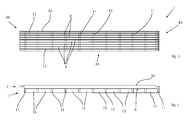
- Fig. 1 and 2 show an acoustic panel 1 of a base plate 2, ie a coated, divided into plate sections wood-based panel 2a, here an MDF board.
- the base plate 2 has on a top side 5 a cover layer (not shown here), here a decorative layer and a structure layer arranged above the decorative layer (not shown here) for producing a haptic surface.
- a cover layer not shown here
- a structure layer arranged above the decorative layer (not shown here) for producing a haptic surface.
- a Chems not shown here
- locking profiles 13a, 13b are mutually corresponding, lockable with each other rotary-swivel profiles (see also Fig. 5 ), via which the acoustic panel 1 can be connected to other acoustic acoustic panels 1 (not shown here) without binder to form a surface without offset.
- correspondingly shaped locking profiles 10 are arranged for vertical Aufratetzen.
- the decorative layer is designed as a lacquer layer.
- the counteracting layer is also adapted to this as a lacquer layer.
- the decorative layer shows a wood decor (not shown here).
- the absorber unit 7 is interruption-free, ie continuous (up to the locking profiles adjacent) arranged over the bottom 6 of the base plate 2.
- the absorber unit 7 is connected to the underside 6, here on the lacquer layer formed as a countermix, by means of an adhesive layer (not shown here), here a melt adhesive layer.
- the base plate 2 passing through recesses 8 are introduced.
- the recesses 8 are formed as aligned in the longitudinal direction of the acoustic panel 1 slots.
- the recesses 8 are only partially introduced into the base plate 2.
- the recesses 8 are exposed both in the edge region 9a, 9b of the end faces 3a, 3b and in a central region 9c of the base plate 2, so that the base plate 2 has no recesses 8 in the edge regions 9a, 9b.
- a particularly good stability of the acoustic panel 1 is ensured.
- the recesses 8 protrude through the entire base plate 2 and through the adhesive layer in the absorber unit 7, so that on the visible side of the acoustic panel 1 incident sound waves (not shown here) can be passed through the recesses 8 to the absorber unit 7.
- the base plate 2 has a height of 6 mm and the absorber unit 7 has a height of 8 mm.
- Fig. 3 to 5 show a second embodiment of the acoustic panel 1 with over the entire length of the acoustic panel 1 extending recesses 8.
- the recesses 8 are also arranged in a slot shape and aligned parallel to each other in the longitudinal axis direction.
- At the bottom 6 of the base plate 2 are reinforcing elements 11 (in Fig. 3 represented by dashed lines) which extend transversely to the longitudinal direction of the acoustic panel 1 and are connected thereto.
- the reinforcing elements 11 are also formed as strips, here corresponding to the base plate 2 made of MDF, and glued to the bottom 6. Between the reinforcing elements 11 absorber elements 15 of the absorber unit 7 are arranged.
- the height of the absorber unit 7 is (not shown here) about 10% higher than the height of the reinforcing elements 11. Due to the over the entire length of the acoustic panel 1 extending recesses 8 is a particularly good sound absorption by the acoustic panel 1 when hitting sound waves reached. In addition, this embodiment of the acoustic panel 1 offers the possibility of forming jointless acoustic panel surfaces with uninterrupted recesses 8.
- the recesses 8 extend through the entire base plate 2 through into the individual absorber elements 15 of the absorber unit 7 or into the reinforcing elements 11 and form in these grooves 14.
- the recesses 8 For a uniform appearance are also in the longitudinal outer area of the acoustic panel 1 extending into the wood-based panel 2a extending DekorausEnglishept 12, which are formed on the one hand for a uniform appearance of the acoustic panel 1 and the other for a dispersion of the impinging sound waves.
- acoustic panel 1 has according to the embodiment Fig. 1 and 2 on the end faces 4a, 4b and on the longitudinal sides 3a, 3b in each case corresponding locking profiles, which are designed as a rotary-swivel profiles or as a vertical locking profiles 10.
Landscapes
- Engineering & Computer Science (AREA)
- Architecture (AREA)
- Civil Engineering (AREA)
- Structural Engineering (AREA)
- Physics & Mathematics (AREA)
- Acoustics & Sound (AREA)
- Electromagnetism (AREA)
- Life Sciences & Earth Sciences (AREA)
- Wood Science & Technology (AREA)
- Building Environments (AREA)
- Finishing Walls (AREA)
Abstract
Description
- Die Erfindung betrifft ein Akustikpaneel gemäß des Oberbegriffs des unabhängigen Anspruchs 1 und ein Verfahren zum Herstellen eines Akustikpaneels gemäß des Oberbegriffs des unabhängigen Anspruchs 11.
- Akustikelemente zur Verwendung als Wand- oder Deckenbelag dienen der Beeinflussung der Raumakustik. Die Raumakustik wird von direkt von einer Schallquelle abgestrahlten Schallwellen und von Wänden, Decken und Einrichtungsgegenständen reflektierten Schallwellen, die in einem Raum auftreten beeinflusst. Entscheidend für die Verbesserung der Raumakustik ist die Verminderung der direkten Schallreflexion im Raum. Als Maß hierfür dient der Schallabsorptionsgrad der jeweiligen Materialien.
- Akustikelemente sind insbesondere zum Einsatz in Besprechungsräumen, Eingangsbereichen, Gaststätten, Büros, Konzerthallen, Versammlungsräumen, Schulen oder Sportstätten vorgesehen. Ein derartiges Akustikelement ist bspw. aus der
DE 10 2014 207 852 A1 bekannt, das ein Paneel mit einer Holzfaserdämmplatte, einer Holzwerkstoffplatte und einer auf der Holzwerkstoffplatte aufliegenden sichtbaren Vollholzoberfläche offenbart, wobei in die Vollholzoberfläche und die Holzwerkstoffplatte Schlitze bis in den Holzfaserdämmstoff eingebracht sind. Zum Verbinden der Paneele ist eine Nutfederverbindung in der Holzwerkstoffplatte vorgesehen. Weitere Akustikelemente sind bspw. aus derDE 20 2009 016 944 U1 , derEP 2 216 773 B1 und derWO 2006/056351 A1 bekannt. - Bekannte Akustikpaneele sind mehrschichtig aufgebaut und weisen eine zum Raum hin ausgerichtete mit Perforationen oder anderen Ausnehmungen versehene Sichtoberfläche auf, die dazu ausgebildet ist, dass die Schallwellen durch sie hindurch in eine Absorberoberfläche eindringen und sich dort verlaufen. Der strukturelle Aufbau der bekannten Paneele ist zum Erreichen eines hohen Wirkungsgrades besonders aufwendig ausgestaltet. Jedes Paneel ist als eigenständiges Bauelement ausgebildet und zum jeweils separaten Befestigen an der Wand oder Decke vorgesehen. Das Herstellen optisch besonders ansprechender, akustisch besonders wirksamer und präzise montierbarer Akustikpaneele, d.h. Akustikpaneele mittels der ohne Versatz montierbare Belagsoberflächen hergestellt werden können, ist mit den bekannten Akustikpaneelen und Herstellungsverfahren aufwendig und kostenintensiv.
- Der Erfindung liegt somit die Aufgabe zugrunde, ein strukturell besonders einfach aufgebautes und kostengünstig herstellbares Akustikpaneel bereitzustellen, mit dem versatzlose und optisch ansprechende Oberflächen ausgebildet werden können. Weiter ist es Aufgabe, ein entsprechendes Verfahren zum Herstellen eines derartigen Akustikpaneels bereitzustellen.
- Die Erfindung löst die Aufgabe durch ein Akustikpaneel mit den Merkmalen des Anspruchs 1 und ein Verfahren mit den Merkmalen des Anspruchs 11. Vorteilhafte Weiterbildungen der Erfindung sind in den abhängigen Ansprüchen angegeben. Dabei sind die beschriebenen Merkmale für sich oder in beliebiger Kombination grundsätzlich Gegenstand der Erfindung, unabhängig von ihrer Zusammenfassung in den Ansprüchen oder deren Rückbeziehung.
- Das erfindungsgemäße Akustikpaneel zur Verwendung als Decken- und/oder Wandbelag weist eine Basisplatte auf, die mindestens eine Holzwerkstoffplatte mit einer Oberseite und einer Unterseite und einer auf der Oberseite angeordneten Deckschicht umfasst und die an den Längsseiten und/oder Stirnseiten zueinander korrespondierende Verriegelungsprofile zum klebstofffreien Verbinden mit weiteren Akustikpaneelen und eine an der Unterseite angeordneten Absorbereinheit zum Absorbieren von Raumschall und eine Vielzahl die Basisplatte vollständig durchsetzende Ausnehmungen zum Durchleiten von auf die Oberseite treffenden Raumschalls in die Absorbereinheit aufweist.
- Die Ausführung des Akustikpaneels mit korrespondierenden Verriegelungsprofilen ermöglicht in besonders einfacher Weise, Wand- und Deckenbeläge mit versatzlosen Oberflächen herzustellen, da die Verriegelungsprofile ein versatzloses Verbinden der Akustikpaneele garantieren. Selbst bei Unebenheiten an der direkten Wand- oder Deckenoberfläche, bzw. bei den Befestigungsmitteln für die Akustikpaneele ist die von den Akustikpaneelen erzeugte im Raum sichtbare Oberfläche versatzlos. Aufgrund der Verrieglungsprofile ist zudem gewährleistet, dass die Oberfläche dauerhaft versatzlos bleibt und die Positionierung der einzelnen Paneele zueinander dauerhaft gleich bleibend ist, so dass bspw. selbst bei Setztätigkeiten des Bauwerks und/oder bei klimabedingten Veränderungen einzelner Baustoffe, wie bspw. der Holzwerkstoffplatte, die Oberfläche des erzeugten Belages dauerhaft gleichbleibend erhalten bleibt. Unter versatzlos wird verstanden, dass die Paneeloberflächen in einer Ebene angeordnet sind.
- Das erfindungsgemäße Akustikpaneel kann durch ein auf das Akustikpaneel abgestimmtes Verfahren hergestellt werden, das besonders kostengünstig ist, da einzelne Verfahrensschritte zumindest teilweise aus der Herstellung von Fußboden-, Wand- oder Deckenlaminaten bekannt sind. Ein weiterer besonderer Vorteil des erfinderischen Akustikpaneels ist, dass alternativ auch ein an sich bekanntes und in großer Vielfalt kostengünstig herstellbares Fußboden-, Wand- oder Deckenlaminat durch Modifikation mit den entsprechenden Ausnehmungen und dem Verbinden mit einer unterseitigen Absorbereinheit besonders kostengünstig zu einem erfinderischen Akustikpaneel weiterverarbeitet werden kann. Der besonders einfache strukturelle Aufbau des erfinderischen Akustikpaneels ermöglicht es somit jedes als Wand-, Decken- oder Fußbodenlaminat bekannte Paneel auf einfache und kostengünstige Weise zum Akustikpaneel zu modifizieren.
- Unter Decken- und Wandbelägen sind vom Rauminnern aus sichtbare Beschichtungen (Verkleidungen, Beläge) auf den Wänden und Decken zu verstehen. Diese können entweder direkt mit der Wand oder der Decke verbunden oder über eine Befestigungsvorrichtung und entsprechende Verbindungsmittel wie bspw. über Abhang- oder Unterdecken, Clipsysteme, sowie Schienensysteme mit Montagekrallen an diesen angeordnet sein.
- Die Holzwerkstoffplatte kann insbesondere eine Spanplatte oder Faserplatte, bspw. eine MDF- oder HDF-Platte, oder eine mineralfasergebundene Platte, sein. Dabei ist die Holzwerkstoffplatte in Abhängigkeit vom vorgesehenen Einsatzgebiet insbesondere als formaldehydarm oder formaldehydfrei verleimte Holzwerkstoffplatte mit einer Formaldehydausgleichskonzentration von ≤ 0,02 ppm, entsprechend EN 717-1, ausgebildet. Hierzu kann die verwendete Holzwerkstoffplatte insbesondere ein formaldehydfreies Bindemittel, bspw. ein Isocyanat aufweisen. Somit können die für das erfinderische Akustikpaneel vorzugsweise verwendeten Span-, oder Faserplatten zumindest in großen Teilen Isocyanat als Bindemittel enthalten. Zudem können die Holzwerkstoffplatten weitere Additive, wie bspw. Brandhemmer, enthalten.
- Unter einer Basisplatte wird ein einzelner Abschnitt einer in mehrere Abschnitte aufgeteilten, beschichteten Holzwerkstoffplatte verstanden, die noch keine Profilierung an den Längs-, und/oder Querseiten aufweist. Dementsprechend kann auch die Basisplatte eine Spanplatte oder eine Faserplatte, bspw. eine MDF- oder HDF-Platte, umfassen. Eine Basisplatte weist zudem zumindest weitestgehend die spätere Paneellänge und Paneelbreite auf und kann auf der Oberseite neben mindestens einer Deckschicht, bspw. einer Dekorschicht, weitere Beschichtungs-Schichten aufweisen. Zudem kann die Basisplatte auch an der Unterseite eine Beschichtung aus einer Schicht oder mehreren Schichten, bspw. eine unterseitige Unterzugbeschichtung, aufweisen. Die Basisplatte ist mit Beschichtungen vorzugsweise zwischen 4 mm und 12 mm dick.
- Unter einem Paneel (bspw. Akustikpaneel) wird im Zusammenhang mit der Erfindung eine Basisplatte mit zueinander korrespondierenden Verriegelungsprofilen an den Stirnund/oder Längsseiten der Basisplatte verstanden.
- Die Verriegelungsprofile des Paneels sind zum klebstofffreien Verbinden mehrerer Paneele untereinander ausgebildet. Dabei können jeweils die an den Längsseiten angeordneten Profile und die an den Querseiten (Stirnseiten) angeordneten Profile zueinander korrespondieren, so dass mittels einer Mehrzahl von Akustikpaneelen eine vollständig ebene (absatzlose) Fläche (Wand- oder Deckenbelag) ausgebildet werden kann.
- Die Deckschicht kann, wie bereits erwähnt, insbesondere als Dekorschicht ausgebildet sein. Dabei kann die Dekorschicht insbesondere einfarbig ausgebildet sein oder ein Holzdekor, eine Steinoberfläche, ein Fliesendekor oder ein Fantasiedekor zeigen. Alternativ kann die Deckschicht bspw. auch als Nutzschicht ausgebildet sein. Die Deckschicht kann zudem mehrlagig sein.
- Eine ggf. an der Unterseite angeordnete Beschichtung kann bspw. als Gegenzug ausgebildet sein und eine oder mehrere Schichten umfassen. Die Beschichtung kann an die Absorbereinheit angrenzend angeordnet bzw. mit der Absorbereinheit verbunden sein. Die als Gegenzug wirkende Schicht kann bspw. bei der Ausbildung der Dekorschicht mittels eines Dekorpapiers ein Gegenzugpapier sein. Bei einem direkt bedruckten Paneel kann bspw. eine Lackschicht, die als Gegenzug zur Dekorschicht wirkt, angeordnet sein.
- Unter der Unterseite wird im Weiteren somit die der Deckschicht gegenüberliegende unterseitige Oberfläche der Holzwerkstoffplatte, der Basisplatte oder des Paneels/Akustikpaneels verstanden, die entsprechend dem Kontext unbeschichtet oder beschichtet (bspw. mit einer Gegenzugschicht) sein kann. Um bspw. von beiden Seiten sichtbare Elemente zur Raumteilung bereitzustellen, kann die Unterseite alternativ auch mit einer oder mehreren Deckschichten, bspw. einer Dekorschicht, beschichtet sein.
- Unter einer Absorbereinheit wird ein Baukörper verstanden, der zur Aufnahme der Schallwellen ausgebildet ist und in dem sich die Schallwellen zerstreuen. Absorbereinheiten weisen insbesondere eine besonders geringe Dichte im Bereich von 50 kg/m3 bis 300 kg/m3 auf und sind bevorzugt offenporig ausgebildet. Absorbereinheiten können bspw. aus Kunststoffen bestehen. Vorzugsweise sind die Absorbereinheiten jedoch aus Holzwerkstoff, bspw. aus einer Holzfaserdämmplatte, ausgebildet. Die Absorbereinheit ist insbesondere plattenförmig ausgebildet und flächig mit der Holzwerkstoffplatte oder deren Beschichtung verbunden.
- Die Ausnehmungen in der Basisplatte können unterschiedliche geometrische Formen aufweisen. Sie können bspw. als runde oder eckige Löcher oder auch schlitzförmig ausgebildet sein. Die Ausnehmungen sind nebeneinander in Längs- und/oder Querrichtung des Paneels angeordnet. Die Ausnehmungen durchsetzen die Basisplatte vollständig, d.h., die Ausnehmungen durchsetzen neben der Holzwerkstoffplatte auch alle Schichten der Beschichtung, d.h. sowohl die Deckschicht oder weitere Schichten auf der Oberseite, als auch alle auf die Unterseite aufgetragenen Schichten, wie bspw. eine Gegenzugschicht. Die Ausnehmungen sind somit dazu ausgebildet, dass auf die Beschichtung auf der Oberseite auftreffende Schallwellen durch die Ausnehmungen hindurch geleitet werden, auf die Absorbereinheit treffen, in diese eindringen und sich in dieser zerstreuen.
- Ergänzend können neben den die Basisplatte vollständig durchsetzenden Ausnehmungen, insbesondere in Randbereichen des Paneels, Dekorausnehmungen angeordnet sein, die durch die Deckschicht bis in die Holzwerkstoffplatte hineinragen, diese jedoch nicht durchdringen. Die Dekorausnehmungen gewährleisten eine besonders hohe Stabilität des Akustikpaneels im Randbereich und somit eine besonders sichere und dauerhafte Verbindung mehrerer Akustikpaneele miteinander mittels der bindemittelfreien Verriegelungsprofile.
- Die Absorbereinheit kann direkt bei der Herstellung der Basisplatte, bspw. mit Hilfe eines an der Unterseite angeordneten klebenden Gegenzuges, mit der Holzwerkstoffplatte verbunden werden. Nach einer Weiterbildung der Erfindung ist jedoch zwischen der Unterseite (d.h. der Oberfläche der Holzwerkstoffplatte oder der ggf. vorliegenden Beschichtung) und der Absorbereinheit eine zusätzliche Klebstoffschicht zum Verbinden der Absorbereinheit mit der Unterseite angeordnet. Dies kann insbesondere ein Schmelzkleber (HotMelt), eine Klebfolie oder ein Einkomponentenklebstoff, wie z.B. Weißleim, sein.
- Gemäß einer Weiterbildung der Erfindung ist vorgesehen, dass die Ausnehmungen die Klebstoffschicht durchsetzen. D.h., die Ausnehmungen ragen durch die Klebstoffschicht hindurch. Hierdurch wird eine deutliche Verbesserung der Schallabsorption erreicht, da die in die Ausnehmungen eindringenden Schallwellen besonders einfach in die Absorbereinheit eindringen können und nicht von der Klebstoffschicht reflektiert werden.
- Zudem ist nach einer Weiterbildung der Erfindung vorgesehen, dass die Ausnehmungen bis in die Absorbereinheit ragen. D.h., die Ausnehmungen ragen über die Unterseite des Paneels und eine ggf. angeordnete Klebstoffschicht hinaus in die Absorbereinheit hinein, so dass in der Absorbereinheit ebenfalls Ausnehmungen angeordnet sind. Vorzugsweise durchdringen die Ausnehmungen die Absorbereinheit dabei nicht. Die sich in die Absorbereinheit erstreckenden Ausnehmungen verbessern die Schallabsorption nochmals deutlich.
- Besonders bevorzugt ist zudem vorgesehen, dass die das Paneel durchsetzenden Ausnehmungen und ggf. auch die Dekorausnehmungen sich über die gesamte Länge des Akustikpaneels erstrecken, wodurch eine weiter verbesserte Schallabsorption des auf das Paneel treffenden Schalls ermöglicht wird.
- Nach einer Weiterbildung der Erfindung sind an der Unterseite, insbesondere quer zur Längsrichtung der Holzwerkstoffplatte bzw. Basisplatte oder quer zu einer Längsrichtung der Ausnehmungen ausgerichtete Verstärkungselemente angeordnet. Die Verstärkungselemente können bspw. als Leisten (stabförmig) ausgebildet sein. Die Verstärkungselemente sind mit der Unterseite verbunden, insbesondere verklebt, und sorgen für eine erhöhte Festigkeit des Paneels, bspw. bei einer hohen Anzahl von das Paneel durchsetzenden Ausnehmungen. Die Verstärkungselemente sind insbesondere an das Material der Holzwerkstoffplatte angepasst und bestehen somit bevorzugt aus Holzwerkstoff, wie Spanplatte, HDF oder MDF. Die Verstärkungselemente sind bevorzugt beabstandet zueinander angeordnet, wobei bspw. im Bereich der Stirnseiten, insbesondere an die stirnseitigen Verriegelungsprofile angrenzend, jeweils ein in Querrichtung des Paneels ausgerichtetes Verstärkungselement angeordnet ist.
- Die Verstärkungselemente sind bevorzugt zwischen 10 mm - 50 mm, insbesondere 20 mm +/-2 mm breit. Die Verstärkungselemente sind in ihrer Dicke an die Dicke der Absorbereinheit angepasst. Bspw. abhängig vom Pressdruck bzw. dem angewendeten Pressverfahren beim Verpressen des Verstärkungselementes mit der Basisplatte ist die Dicke des Verstärkungselementes gleich der Dicke des Absorbereinheit oder bis zu 20% niedriger als die Absorbereinheit ausgebildet, wodurch ein sicheres Verpressen von Verstärkungselement und Absorberelement mit der Unterseite gewährleistet ist. Insbesondere zur Ausbildung von besonders dünnen Akustikpaneelen mit einer Höhe von 15 mm +/- 5 mm ist die Absorbereinheit, entsprechend an die Höhe der Basisplatte angepasst, zwischen 4 mm bis 14 mm hoch ausgebildet. Die besonders bevorzugten Maße gewährleisten ein optimales Verhältnis aus hoher Stabilität, geringen Herstellungskosten, minimaler Dicke und hohen Schallabsorptionsraten. Besonders gute Schallabsorptionsraten werden zudem ab einem Höhenverhältnis von ca. 1:1 zwischen Basisplatte und Absorbereinheit erreicht.
- Die Absorbereinheit ist bevorzugt einstückig, ausgebildet und deckt die Unterseite der Holzwerkstoffplatte weitestgehend (ggf. bis auf Randbereiche) vollständig ab. Bei einer Anordnung von Verstärkungselementen an der Unterseite weist die Absorbereinheit jedoch besonders bevorzugt eine Vielzahl von Absorberelementen auf, die insbesondere zwischen den Verstärkungselementen angeordnet sind. Hierdurch wird eine hohe Schallabsorption bei entsprechend ausreichend hoher Festigkeit des Akustikpaneels erreicht. Die bereits erwähnte von der Höhe der Basisplatte abhängige optimierte Höhe der Absorbereinheit zwischen 4 mm - 14 mm, gewährleistet eine optimale Schallabsorption, so dass ein besonders dünnes Akustikpaneel mit einer Höhe von 15 +/- 5 mm bereitgestellt werden kann. Der besonders dünne Aufbau des Akustikpaneels ermöglicht es, wie bereits oben erwähnt, Räume, in denen bei der Bauplanung keine Akustikpaneele vorgesehen waren, ohne wesentliche Raumverluste mit Akustikpaneelen nachzurüsten.
- Die auf der Oberseite angeordnete Deckschicht kann als Vollholzschicht ausgebildet sein, ist besonders bevorzugt jedoch als auf die Oberfläche der Holzwerkstoffplatte aufgetragene Schicht aus PVC, PE, PP, Polyester, PU, als Schichtstoff, HPL, DPL, CPL, Folie, Acrylfolie, und/oder als auf die Oberfläche aufgedruckte Lack- und/oder Kunstharzschicht ausgebildet, die bspw. im Digitaldruck aufgetragen wird. Die Deckschicht kann zudem sämtliche für das Auftragen der Deckschicht oder einer Dekorschicht notwendigen Hilfsschichten, wie bspw. Klebschichten, Grundierungen, Spachtelschichten usw., umfassen.
- Besonders bevorzugt ist zudem (außenseitig) eine (insbesondere transparente) Nutzschicht und/oder Strukturschicht oder eine strukturierte Nutzschicht zur Verbesserung der Oberflächenbeständigkeit des Akustikpaneels vor äußeren Einflüssen, bzw. zur optischen Aufwertung und/oder haptischen Ausbildung der Oberfläche, angeordnet. Die Nutzschicht und/oder Strukturschicht kann bspw. als Kunstharzschicht oder Overlayjeweils flüssig oder fest aufgetragen werden. Insbesondere wird die Nutzschicht und/oder Strukturschicht mittels eines schichtbildenden digitalen Druckverfahrens aufgetragen. Einzelne Schichten, wie bspw. eine Strukturschicht, können nur abschnittsweise aufgetragen sein, um eine haptische, bspw. auf das Dekor abgestimmte, negative oder positive Oberflächenstruktur zu erzeugen.
- Die Profile an den Längsseiten und Querseiten sind besonders bevorzugt als Rastprofile, d.h. zum gegenseitigen Verriegeln, ausgebildet. Dabei sind die Profile insbesondere als Dreh-Schwenk-Profil oder als vertikales Rastprofil ausgebildet. Vertikal heißt, dass zwei zueinander korrespondierende Profile in einer senkrecht zur Oberseite zeigenden Richtung ineinander bringbar sind.
- Vorzugsweise sind die Profile an den Längsseiten und den Querseiten korrespondierend zueinander, so dass ein erstes Paneel mit einer Querseite in eine Längsseite eines zweiten Paneels eingerastet werden kann. Hierzu können die Profile bspw. als Dreh-Schwenk-Profil oder vertikales Rastprofil ausgebildet sein. Bei der Ausführung von bspw. rechteckigen Paneelen können somit eine Vielzahl von unterschiedlichen Verlegemustern (bspw. Querseite an Längsseite) verwirklicht werden.
- Alternativ weisen jeweils die Querseiten korrespondierende Verriegelungsprofile, bspw. vertikale Rastprofile, und jeweils die Längsseiten korrespondierende Verriegelungsprofile, bspw. Dreh-Schwenk-Profile auf, wodurch insbesondere die Montage der Akustikpaneele im Wand- oder Deckenbereich deutlich erleichtert wird.
- Die Befestigung der Akustikpaneele kann direkt an einer Wand oder Decke bspw. durch Klebemittel erfolgen. Vorzugsweise werden die Akustikpaneele jedoch über bspw. mechanische Verbindungsmittel an einer an der Wand oder Decke angeordneten Befestigungsvorrichtung zur Aufnahme der Paneele angebracht. Besonders bevorzugt ist hierfür im Bereich der längsseitigen Verriegelungsprofile ein Mittel zur Aufnahme von Verbindungsmitteln für die Befestigung des Akustikpaneels an der Befestigungsvorrichtung angeordnet. Die Mittel am Akustikpaneel sind auf die Verbindungsmittel abgestimmt. Hierfür ist vorzugsweise das längsseitige Verriegelungsprofil zumindest abschnittsweise modifiziert und zur Aufnahme des Verbindungsmittels ausgebildet, bspw. durch eine zumindest abschnittsweise Veränderung der Profilgeometrie. Alternativ oder ergänzend ist eine Ausnehmung, bspw. eine Nut in unmittelbare Nähe des längsseitigen Profils, bspw. im Bereich eines Profilgrundes (Nutgrund) oder an einem unterseitigen Abschnitt des Paneels angeordnet.
- Weiter wird die Aufgabe der Erfindung gelöst durch ein Verfahren zum Herstellen eines Akustikpaneels mit den Schritten: Beschichten einer eine Oberseite und eine Unterseite aufweisenden Holzwerkstoffplatte mit mindestens einer Deckschicht auf der Oberseite, Aufschneiden der Holzwerkstoffplatte zum Erzeugen von Basisplatten, Profilieren von Längs- und/oder Stirnseiten der Basisplatte mit Verriegelungsprofilen zum klebstofffreien Verbinden mehrerer Akustikpaneele miteinander, Verbinden einer Absorbereinheit mit der Unterseite, Einbringen von die Basisplatte vollständig durchsetzenden Ausnehmungen, zum Durchleiten von auf die Oberseite der Basisplatte treffenden Raumschalls in die Absorbereinheit.
- Das erfindungsgemäße Verfahren ermöglicht die Herstellung eines in seiner Struktur besonders einfach aufgebauten Akustikpaneels mit besonders hohem Schallabsorptionsgrad. Dabei werden zahlreiche zumindest in Teilen aus der Herstellung von Wand-, Decken- oder Fußbodenlaminaten bekannte Verfahrensschritte genutzt, wodurch das Akustikpaneel besonders kostengünstig hergestellt werden kann. Zudem ermöglicht das Verfahren die Herstellung besonders dünner Akustikpaneele im Dickenbereich von 15 mm +/- 5 mm mit besonders hohem Schallabsorptionsgrad, wodurch auch eine Nachrüstung von Akustikpaneelen in Räumen, in denen ursprünglich keine Akustikpaneele vorgesehen sind, ermöglicht wird. Abhängig von der gewählten Reihenfolge der Verfahrensschritte sind unterschiedliche Herstellungsverfahren ausführbar.
- Nach einer Weiterbildung der Erfindung werden zuerst die Verfahrensschritte Beschichten, Aufschneiden und Profilieren nacheinander und nachfolgend das Verbinden und Einbringen in beliebiger Reihenfolge durchgeführt. D.h., dass zuerst ein Wand-, Decken- oder Fußbodenlaminat hergestellt wird (Beschichten, Aufschneiden und Profilieren) und anschließend erfolgt die Modifizierung des fertig hergestellten Paneels in ein Akustikpaneel durch das Aufbringen der Absorbereinheit und das Einbringen der Ausnehmungen. Dabei kann das Paneel bspw. nach dem Profilieren auch vorerst eingelagert und erst bei entsprechendem Bedarf aus dem Lager entnommen und zu einem Akustikpaneel weiterverarbeitet werden.
- Neben der Modifizierung von bereits bestehenden Paneelen können gemäß einer Weiterbildung des Verfahrens auch zuerst die Verfahrensschritte Beschichten, Verbinden, Aufschneiden und Profilieren nacheinander und nachfolgend oder gleichzeitig mit dem Verbinden, Aufschneiden oder Profilieren das Einbringen durchgeführt werden. Hierdurch kann unter Ausnutzung zum Teil bekannter Verfahrensschritte eine großformatige Holzwerkstoffplatte in einem speziell auf die Herstellung von Akustikpaneelen ausgerichteten Verfahren besonders kostengünstig hergestellt werden.
- Abhängig von der Ausgestaltung des Akustikpaneels kann die Absorbereinheit auch aus mehreren Absorberelementen bestehen, so dass zum Anordnen der Absorbereinheit mehrere Absorberelemente ggf. mit Verstärkungselementen aufgebracht werden.
- Insbesondere im Zusammenhang mit dem Beschichten können zahlreiche zusätzliche Verfahrenschritte durchgeführt werden. So kann bspw. eine entsprechende Gegenzugschicht auf die Unterseite aufgebracht werden oder es können weitere Schichten auf oder unter die Deckschicht aufgetragen werden. Insbesondere können Grundierungs-, Nutz- und/oder Strukturschichten angeordnet werden.
- Nach einer Weiterbildung der Erfindung wird eine Verbindungsmittelaufnahme zur Aufnahme eines Verbindungsmittels, welches zur Befestigung des Paneels an einer Befestigungsvorrichtung ausgebildet ist, angeordnet. Die Verbindungsmittelaufnahme kann in die Holzwerkstoffplatte oder die Absorbereinheit eingebracht werden. Insbesondere wird die Verbindungsmittelaufnahme jedoch in die Basisplatte oder mindestens ein Verstärkungselement eingebracht, um einen besonders sicheren Halt der Paneele an der Befestigungsvorrichtung zu gewährleisten. Vorzugsweise wird die Verbindungsmittelausnehmung gleichzeitig oder nach dem Profilieren oder dem Einbringen der die Basisplatte durchsetzenden Ausnehmungen eingebracht, wodurch eine besonders effiziente Produktion möglich ist. Die Verbindungsmittelausnehmung wird bspw. als sich in Längsrichtung des Paneels erstreckende Nut ausgebildet.
- Obwohl manche Aspekte im Zusammenhang mit einer Vorrichtung beschrieben wurden, versteht es sich, dass diese Aspekte auch eine Beschreibung des entsprechenden Verfahrens darstellen, so dass ein Block- oder ein Bauelement einer Vorrichtung auch als ein entsprechender Verfahrensschritt oder als ein Merkmal eines Verfahrensschrittes zu verstehen ist. Analog dazu stellen Aspekte, die im Zusammenhang mit einem oder als ein Verfahrensschritt beschrieben wurden, auch eine Beschreibung eines entsprechenden Blocks oder Details oder Merkmals einer entsprechenden Vorrichtung dar.
- Im Weiteren wird die Erfindung anhand von mehreren Ausführungsbeispielen näher beschrieben. Es zeigt:
- Fig. 1
- schematisch in einer Ansicht eine erste Ausführungsform des Akustikpaneels;
- Fig. 2
- schematisch in einem vertikalen Längsschnitt die Ausführungsform aus
Fig. 1 ; - Fig. 3
- schematisch in einer Ansicht eine zweite Ausführungsform des Akustikpaneels;
- Fig. 4
- schematisch in einem vertikalen Längsschnitt die Ausführungsform des Akustikpaneels aus
Fig. 3 ; - Fig. 5
- schematisch in einem vertikalen Querschnitt die Ausführungsform des Akustikpaneels aus
Fig. 3 und 4 . -
Fig. 1 und 2 zeigen ein Akustikpaneel 1 aus einer Basisplatte 2, d.h. einer beschichteten, in Plattenabschnitte aufgeteilten Holzwerkstoffplatte 2a, hier einer MDF-Platte. Die Basisplatte 2 weist auf einer Oberseite 5 eine Deckschicht (hier nicht dargestellt), hier eine Dekorschicht und eine oberhalb der Dekorschicht angeordnete Strukturschicht (hier nicht dargestellt) zum Herstellen einer haptischen Oberfläche auf. Auf einer Unterseite 6 ist eine Gegenzugschicht (hier nicht dargestellt) angeordnet. - An den Längsseiten 3a, 3b der Basisplatte 2 sind Verriegelungsprofile 13a, 13b hier zueinander korrespondierende, miteinander verriegelbare Dreh-Schwenk-Profile (siehe auch
Fig. 5 ) angeordnet, über die das Akustikpaneel 1 mit weiteren (hier nicht dargestellten) Akustikpaneelen 1 bindemittellos zu einer absatzlosen Fläche verbunden werden kann. An den Stirnseiten 4a, 4b des Akustikpaneels 1 sind zum vertikalen Aufeinandersetzen korrespondierend ausgebildete Rastprofile 10 angeordnet. - Die Dekorschicht ist als Lackschicht ausgebildet. Die Gegenzugschicht ist hieran angepasst ebenfalls als Lackschicht ausgebildet. Die Dekorschicht zeigt ein Holzdekor (hier nicht dargestellt).
- An der als Lackschicht ausgebildeten Gegenzugschicht ist eine Absorbereinheit 7 aus einer Holzfaserdämmplatte mit einer Dichte von 150 kg/m3 angeordnet. Die Absorbereinheit 7 ist unterbrechungsfrei, d.h. durchgängig (bis an die Verriegelungsprofile angrenzend) über die Unterseite 6 der Basisplatte 2 angeordnet. Die Absorbereinheit 7 ist mit der Unterseite 6, hier an der als Gegenzug ausgebildeten Lackschicht, mittels einer Klebstoffschicht (hier nicht dargestellt), hier einer Schmelzkleberschicht, verbunden.
- In das Akustikpaneel 1 sind eine Vielzahl von nebeneinander angeordneten, die Basisplatte 2 durchsetzenden Ausnehmungen 8 eingebracht. Die Ausnehmungen 8 sind als in Längsrichtung des Akustikpaneels 1 ausgerichtete Schlitze ausgebildet. Die Ausnehmungen 8 sind nur partiell in die Basisplatte 2 eingebracht. Die Ausnehmungen 8 sind sowohl im Randbereich 9a, 9b der Stirnseiten 3a, 3b als auch in einem Zentralbereich 9c der Basisplatte 2 ausgesetzt, so dass die Basisplatte 2 in den Randbereichen 9a, 9b keine Ausnehmungen 8 aufweist. Hierdurch wird eine besonders gute Stabilität des Akustikpaneels 1 gewährleistet.
- Die Ausnehmungen 8 ragen durch die gesamte Basisplatte 2 und durch die Klebstoffschicht in die Absorbereinheit 7 hinein, so dass auf die Sichtseite des Akustikpaneels 1 auftreffende Schallwellen (hier nicht dargestellt) durch die Ausnehmungen 8 bis in die Absorbereinheit 7 geleitet werden können. Die Basisplatte 2 weist eine Höhe von 6 mm und die Absorbereinheit 7 eine Höhe von 8 mm auf.
-
Fig. 3 bis 5 zeigen eine zweite Ausführungsform des Akustikpaneels 1 mit sich über die gesamte Länge des Akustikpaneels 1 erstreckenden Ausnehmungen 8. Die Ausnehmungen 8 sind ebenfalls schlitzförmig angeordnet und parallel zueinander in Längsachsenrichtung ausgerichtet. An der Unterseite 6 der Basisplatte 2 sind Verstärkungselemente 11 (inFig. 3 durch gestrichelte Linien dargestellt) angeordnet, die sich quer zur Längsrichtung des Akustikpaneels 1 erstrecken und mit diesem verbunden sind. Die Verstärkungselemente 11 sind als Leisten, hier entsprechend der Basisplatte 2 ebenfalls aus MDF ausgebildet, und mit der Unterseite 6 verklebt. Zwischen den Verstärkungselementen 11 sind Absorberelemente 15 der Absorbereinheit 7 angeordnet. Die Höhe der Absorbereinheit 7 ist (hier nicht dargestellt) um ca. 10 % höher als die Höhe der Verstärkungselemente 11. Aufgrund der sich über die gesamte Länge des Akustikpaneels 1 erstreckenden Ausnehmungen 8 wird eine besonders gute Schallabsorption durch das Akustikpaneel 1 beim Auftreffen von Schallwellen erreicht. Zudem bietet diese Ausführungsform des Akustikpaneels 1 die Möglichkeit, fugenlose Akustikpaneelflächen mit unterbrechungsfreien Ausnehmungen 8 auszubilden. - In vertikaler Richtung erstrecken sich die Ausnehmungen 8 durch die gesamte Basisplatte 2 hindurch bis in die einzelnen Absorberelemente 15 der Absorbereinheit 7 bzw. in die Verstärkungselemente 11 und bilden in diesen Nuten 14 aus. Für ein gleichmäßiges Erscheinungsbild sind zudem im längsseitigen Außenbereich des Akustikpaneels 1 sich bis in die Holzwerkstoffplatte 2a erstreckende Dekorausnehmungen 12 angeordnet, die zum einen für ein gleichmäßiges Erscheinungsbild des Akustikpaneels 1 und zum anderen für eine Zerstreuung der auftreffenden Schallwellen ausgebildet sind.
- Das in
Fig. 3 bis 5 dargestellte Akustikpaneel 1 weist entsprechend der Ausführungsform ausFig. 1 und 2 an den Stirnseiten 4a, 4b und an den Längsseiten 3a, 3b jeweils zueinander korrespondierende Verriegelungsprofile auf, die als Dreh-Schwenk-Profile bzw. als vertikale Rastprofile 10 ausgebildet sind. -
- 1
- Akustikpaneel
- 2
- Basisplatte
- 2a
- Holzwerkstoffplatte
- 3a, 3b
- Längsseiten
- 4a, 4b
- Stirnseiten
- 5
- Oberseite
- 6
- Unterseite
- 7
- Absorbereinheit
- 8
- Ausnehmungen
- 9a, 9b
- Randbereich
- 9c
- Zentralabschnitt
- 10
- vertikales Rastprofil
- 11
- Verstärkungselement
- 12
- Dekorausnehmungen
- 13a, 13b
- Verriegelungsprofil
- 14
- Nuten
- 15
- Absorberelemente
Claims (15)
- Akustikpaneel zur Verwendung als Decken- und Wandbelag, aufweisend- eine Basisplatte (2) mindestens umfassend eine Holzwerkstoffplatte (2a) mit einer Oberseite (5) und einer Unterseite (6) und einer auf der Oberseite (5) angeordneten Deckschicht,- an den Längsseiten (3a, 3b) und/oder Stirnseiten (4a, 4b) der Basisplatte (2) zueinander korrespondierende Verriegelungsprofile (13a, 13b) zum klebstofffreien Verbinden mit weiteren Akustikpaneelen (1),- eine an der Unterseite (6) angeordneten Absorbereinheit (7) zum Absorbieren von Raumschall und- eine Vielzahl die Basisplatte (2) vollständig durchsetzende Ausnehmungen (8) zum Durchleiten von auf die Oberseite (5) des Paneels treffenden Raumschalls in die Absorbereinheit (7).
- Akustikpaneel nach Anspruch 1, dadurch gekennzeichnet, dass zwischen der Unterseite (6) und der Absorbereinheit (7) eine Klebstoffschicht, insbesondere ein Schmelzkleber, eine Klebefolie, oder ein Einkomponentenklebstoff zum Verbinden der Absorbereinheit (7) mit der Unterseite (6) angeordnet ist.
- Akustikpaneel nach Anspruch 1 oder 2, dadurch gekennzeichnet, dass die Ausnehmungen (8) die Klebstoffschicht durchsetzen.
- Akustikpaneel nach einem der vorhergehenden Ansprüche, dadurch gekennzeichnet, dass sich die Ausnehmungen (8) in die Absorbereinheit (7) erstrecken.
- Akustikpaneel nach einem der vorhergehenden Ansprüche, dadurch gekennzeichnet, dass sich die Ausnehmungen (8) über die gesamte Länge des Akustikpaneels (1) erstrecken.
- Akustikpaneel nach einem der vorhergehenden Ansprüche, dadurch gekennzeichnet, dass an der Unterseite (6) zueinander beabstandet angeordnete Verstärkungselemente (11) angeordnet sind und zwischen den Verstärkungselementen mindestens ein Absorberelement (15) angeordnet ist.
- Akustikpaneel nach einem der vorhergehenden Ansprüche, dadurch gekennzeichnet, dass die Deckschicht als PVC-Schicht, PE-Schicht, PP-Schicht, Polyester-Schicht, PU-Schicht, Schichtstoff, HPL, DPL, CPL, Folie, Lack- oder Kunstharzschicht ausgebildet und/oder im Digitaldruck aufgetragen, ist.
- Akustikpaneel nach einem der vorhergehenden Ansprüche, dadurch gekennzeichnet, dass die Deckschicht eine Dekorschicht umfasst, wobei insbesondere oberhalb der Dekorschicht eine Nutzschicht und/oder eine Strukturschicht oder eine strukturierte Nutzschicht angeordnet ist.
- Akustikpaneel nach einem der vorhergehenden Ansprüche, dadurch gekennzeichnet, dass die Verriegelungsprofile als Dreh-Schwenk-Profile und/oder als vertikale Rastprofile ausgebildet sind.
- Akustikpaneel nach einem der vorhergehenden Ansprüche, dadurch gekennzeichnet, dass im Bereich der längsseitigen Verriegelungsprofile Mittel zur Aufnahme von Verbindungsmitteln für die Befestigung des Akustikpaneels an einer Befestigungsvorrichtung angeordnet sind.
- Verfahren zum Herstellen eines Akustikpaneels (1) mit den Schritten:- Beschichten einer eine Oberseite (5) und eine Unterseite (6) aufweisenden Holzwerkstoffplatte (2a), mit mindestens einer Deckschicht auf der Oberseite (5),- Aufschneiden der Holzwerkstoffplatte (2a) zum Erzeugen von Basisplatten (2),- Profilieren von Längs- und/oder Stirnseiten (3a, 3b, 4a, 4b) der Basisplatte (2) mit Verriegelungsprofilen (13a, 13b) zum klebstofffreien Verbinden mehrerer Akustikpaneele (1) miteinander,- Verbinden einer Absorbereinheit (7) mit der Unterseite (6),- Einbringen von die Basisplatte (2) vollständig durchsetzenden Ausnehmungen (8), zum Durchleiten von auf die Oberseite (5) der Basisplatte (2) treffenden Raumschalls in die Absorbereinheit (7).
- Verfahren nach Anspruch 11, dadurch gekennzeichnet, dass zuerst die Verfahrensschritte Beschichten, Aufschneiden und Profilieren nacheinander und nachfolgend das Verbinden und Einbringen in beliebiger Reihenfolge durchgeführt werden.
- Verfahren nach Anspruch 11, dadurch gekennzeichnet, dass zuerst die Verfahrensschritte Beschichten, Verbinden, Aufschneiden und Profilieren und nachfolgend oder gleichzeitig mit dem Verbinden, Aufschneiden oder Profilieren das Einbringen durchgeführt werden.
- Verfahren nach mindestens einem der Ansprüche 11 bis 13, dadurch gekennzeichnet, dass- beabstandet zueinander angeordnete Verstärkungselemente (11) und- zwischen den Verstärkungselementen (11) angeordnete Absorberelemente der Absorbereinheit (7) mit der Unterseite (6) verbunden werden.
- Verfahren nach mindestens einem der Ansprüche 11 bis 14, dadurch gekennzeichnet, dass eine Verbindungsmittelaufnahme zur Aufnahme eines Verbindungsmittels zur Befestigung des Akustikpaneels (1) an einer Befestigungsvorrichtung angeordnet wird.
Priority Applications (10)
| Application Number | Priority Date | Filing Date | Title |
|---|---|---|---|
| ES15174338T ES2764129T3 (es) | 2015-06-29 | 2015-06-29 | Panel acústico |
| PT151743382T PT3112544T (pt) | 2015-06-29 | 2015-06-29 | Painel acústico |
| PL15174338T PL3112544T3 (pl) | 2015-06-29 | 2015-06-29 | Panel akustyczny |
| EP15174338.2A EP3112544B1 (de) | 2015-06-29 | 2015-06-29 | Akustikpaneel |
| EP16176930.2A EP3112545B1 (de) | 2015-06-29 | 2016-06-29 | Akustikpaneel |
| PL16176930T PL3112545T3 (pl) | 2015-06-29 | 2016-06-29 | Panel akustyczny |
| PT16176930T PT3112545T (pt) | 2015-06-29 | 2016-06-29 | Painel acústico |
| TR2018/16156T TR201816156T4 (tr) | 2015-06-29 | 2016-06-29 | Akustik panel. |
| ES16176930T ES2696531T3 (es) | 2015-06-29 | 2016-06-29 | Panel acústico |
| ES17201101T ES2863302T3 (es) | 2015-06-29 | 2017-11-10 | Sistema de sujeción para paneles |
Applications Claiming Priority (1)
| Application Number | Priority Date | Filing Date | Title |
|---|---|---|---|
| EP15174338.2A EP3112544B1 (de) | 2015-06-29 | 2015-06-29 | Akustikpaneel |
Publications (2)
| Publication Number | Publication Date |
|---|---|
| EP3112544A1 true EP3112544A1 (de) | 2017-01-04 |
| EP3112544B1 EP3112544B1 (de) | 2019-10-02 |
Family
ID=53514001
Family Applications (2)
| Application Number | Title | Priority Date | Filing Date |
|---|---|---|---|
| EP15174338.2A Active EP3112544B1 (de) | 2015-06-29 | 2015-06-29 | Akustikpaneel |
| EP16176930.2A Active EP3112545B1 (de) | 2015-06-29 | 2016-06-29 | Akustikpaneel |
Family Applications After (1)
| Application Number | Title | Priority Date | Filing Date |
|---|---|---|---|
| EP16176930.2A Active EP3112545B1 (de) | 2015-06-29 | 2016-06-29 | Akustikpaneel |
Country Status (5)
| Country | Link |
|---|---|
| EP (2) | EP3112544B1 (de) |
| ES (3) | ES2764129T3 (de) |
| PL (2) | PL3112544T3 (de) |
| PT (2) | PT3112544T (de) |
| TR (1) | TR201816156T4 (de) |
Families Citing this family (9)
| Publication number | Priority date | Publication date | Assignee | Title |
|---|---|---|---|---|
| CN109653467B (zh) * | 2019-02-21 | 2020-10-30 | 浙江新概念装饰设计工程有限公司 | 一种可拼装的装修墙板 |
| CN110206258A (zh) * | 2019-06-11 | 2019-09-06 | 广西福美新材料有限公司 | 磁性板材 |
| ES2911046T3 (es) * | 2019-06-18 | 2022-05-17 | SWISS KRONO Tec AG | Panel acústico con ranuras desplazadas |
| CN110565889B (zh) * | 2019-09-05 | 2024-10-08 | 上海金茂建筑装饰有限公司 | 装配式建筑的外墙挂板结构及其装配方法 |
| DE102022130696A1 (de) | 2022-11-21 | 2024-05-23 | Hamberger Industriewerke Gmbh | Akustikaufbau |
| DE102023102894A1 (de) | 2023-02-07 | 2024-08-08 | Hamberger Industriewerke Gmbh | Dekoratives Flächenelement |
| DE102023104919A1 (de) | 2023-02-28 | 2024-08-29 | Hamberger Industriewerke Gmbh | Modulares Akustikplattensystem und Akustikplatte |
| DE202023002736U1 (de) | 2023-03-08 | 2024-04-18 | Hamberger Industriewerke Gmbh | Akustikelement |
| DE102023105733A1 (de) | 2023-03-08 | 2024-09-12 | Hamberger Industriewerke Gmbh | Akustikelement und Verfahren zum Herstellen eines Akustikelements |
Citations (4)
| Publication number | Priority date | Publication date | Assignee | Title |
|---|---|---|---|---|
| DE202006017188U1 (de) * | 2006-10-11 | 2007-02-08 | Hülsta-Werke Hüls Gmbh & Co. Kg | Paneel und Belag aus einer Mehrzahl von Paneelen |
| DE202009016944U1 (de) * | 2009-12-15 | 2010-03-04 | Lignotrend Ag | Holzbautafel für Decken und Wände |
| WO2010089271A1 (de) * | 2009-02-04 | 2010-08-12 | Fritz Egger Gmbh & Co. Og | Fussbodenpaneel sowie verfahren und vorrichtung zu dessen herstellung |
| DE102014207852A1 (de) * | 2013-04-26 | 2014-10-30 | Holzwerke Ladenburger GmbH & Co. KG | Akustikabsorber-Bauelement |
Family Cites Families (4)
| Publication number | Priority date | Publication date | Assignee | Title |
|---|---|---|---|---|
| DE202004018241U1 (de) | 2004-11-24 | 2006-04-06 | Fritz Egger Gmbh & Co | Deckschicht und Paneel mit schallabsorbierenden Eigenschaften |
| DE202005018659U1 (de) * | 2005-11-22 | 2006-01-26 | Strähle, Werner | Schallabsorptionseinrichtung |
| DE202009001318U1 (de) | 2009-02-04 | 2009-04-30 | Eichhorn Gmbh & Co. Kg | Schallabsorbierendes Paneel |
| DE102009033150A1 (de) * | 2009-07-13 | 2011-01-27 | Akzenta Paneele + Profile Gmbh | Befestigungsklammer und Tragschiene sowie Verfahren zur Einrichtung einer Verkleidungsfläche |
-
2015
- 2015-06-29 PL PL15174338T patent/PL3112544T3/pl unknown
- 2015-06-29 EP EP15174338.2A patent/EP3112544B1/de active Active
- 2015-06-29 ES ES15174338T patent/ES2764129T3/es active Active
- 2015-06-29 PT PT151743382T patent/PT3112544T/pt unknown
-
2016
- 2016-06-29 PT PT16176930T patent/PT3112545T/pt unknown
- 2016-06-29 EP EP16176930.2A patent/EP3112545B1/de active Active
- 2016-06-29 TR TR2018/16156T patent/TR201816156T4/tr unknown
- 2016-06-29 PL PL16176930T patent/PL3112545T3/pl unknown
- 2016-06-29 ES ES16176930T patent/ES2696531T3/es active Active
-
2017
- 2017-11-10 ES ES17201101T patent/ES2863302T3/es active Active
Patent Citations (4)
| Publication number | Priority date | Publication date | Assignee | Title |
|---|---|---|---|---|
| DE202006017188U1 (de) * | 2006-10-11 | 2007-02-08 | Hülsta-Werke Hüls Gmbh & Co. Kg | Paneel und Belag aus einer Mehrzahl von Paneelen |
| WO2010089271A1 (de) * | 2009-02-04 | 2010-08-12 | Fritz Egger Gmbh & Co. Og | Fussbodenpaneel sowie verfahren und vorrichtung zu dessen herstellung |
| DE202009016944U1 (de) * | 2009-12-15 | 2010-03-04 | Lignotrend Ag | Holzbautafel für Decken und Wände |
| DE102014207852A1 (de) * | 2013-04-26 | 2014-10-30 | Holzwerke Ladenburger GmbH & Co. KG | Akustikabsorber-Bauelement |
Also Published As
| Publication number | Publication date |
|---|---|
| PT3112544T (pt) | 2020-01-14 |
| EP3112545A2 (de) | 2017-01-04 |
| EP3112545A3 (de) | 2017-03-29 |
| ES2863302T3 (es) | 2021-10-11 |
| ES2696531T3 (es) | 2019-01-16 |
| PL3112545T3 (pl) | 2019-01-31 |
| EP3112545B1 (de) | 2018-08-15 |
| TR201816156T4 (tr) | 2018-11-21 |
| PT3112545T (pt) | 2018-11-26 |
| EP3112544B1 (de) | 2019-10-02 |
| PL3112544T3 (pl) | 2020-04-30 |
| ES2764129T3 (es) | 2020-06-02 |
Similar Documents
| Publication | Publication Date | Title |
|---|---|---|
| EP3112544B1 (de) | Akustikpaneel | |
| DE102006058655B4 (de) | Bodenpaneel | |
| EP2130991B1 (de) | Holzwerkstoffplatte, insbesondere für Fußbodenpaneele | |
| EP0023618B1 (de) | Schallschluckende Bauplatte und Verfahren zu ihrer Herstellung | |
| DE102009041099A1 (de) | Fußbodenpaneel sowie Verfahren und Vorrichtung zu dessen Herstellung | |
| EP3329066B1 (de) | Wandkonstruktion und verfahren zum montieren | |
| DE202022002917U1 (de) | Plattenförmiges Element für die Wand- und Deckenverkleidung | |
| DE102011115897A1 (de) | Leichtbauplatte, Verfahren zur Herstellungund Vorrichtung zur Herstellung | |
| EP2230364B1 (de) | Fussbodenplatte mit Steinoberfläche | |
| EP2295240B1 (de) | Verfahren zum Herstellen eines schalldämmenden Paneels | |
| DE10011798A1 (de) | Schallabsorbierendes Paneel | |
| EP0973983B1 (de) | Plattenförmiges element nach art einer fliese | |
| EP2170599A1 (de) | Leichtbauplatte | |
| DE202008001822U1 (de) | Fußbodenplatte mit Steinoberfläche | |
| DE102007063646B4 (de) | Wand-oder Deckenverkleidung | |
| DE202023002736U1 (de) | Akustikelement | |
| DE102023105733A1 (de) | Akustikelement und Verfahren zum Herstellen eines Akustikelements | |
| DE102012111019A1 (de) | Paneelsystem für die Montage an Wänden, Decken oder Böden | |
| EP1867796B1 (de) | Verbundplatte für den Innenausbau | |
| EP3670783B1 (de) | Montageclip zur schwimmenden lagerung von wand- und deckenpaneelen | |
| EP1380699B1 (de) | Schallabsorbierendes Paneel | |
| DE4400666A1 (de) | Deckenplatte | |
| EP1398425A1 (de) | Wandsystem | |
| EP2907958B1 (de) | Verfahren zur Herstellung von Türblättern | |
| CH721744A2 (de) | Bodenbelagselement zur losen Verlegung sowie Herstellungsverfahren für ein Bodenbelagselement |
Legal Events
| Date | Code | Title | Description |
|---|---|---|---|
| PUAI | Public reference made under article 153(3) epc to a published international application that has entered the european phase |
Free format text: ORIGINAL CODE: 0009012 |
|
| STAA | Information on the status of an ep patent application or granted ep patent |
Free format text: STATUS: THE APPLICATION HAS BEEN PUBLISHED |
|
| AK | Designated contracting states |
Kind code of ref document: A1 Designated state(s): AL AT BE BG CH CY CZ DE DK EE ES FI FR GB GR HR HU IE IS IT LI LT LU LV MC MK MT NL NO PL PT RO RS SE SI SK SM TR |
|
| AX | Request for extension of the european patent |
Extension state: BA ME |
|
| RAP1 | Party data changed (applicant data changed or rights of an application transferred) |
Owner name: SWISS KRONO TEC AG |
|
| STAA | Information on the status of an ep patent application or granted ep patent |
Free format text: STATUS: REQUEST FOR EXAMINATION WAS MADE |
|
| 17P | Request for examination filed |
Effective date: 20170627 |
|
| RBV | Designated contracting states (corrected) |
Designated state(s): AL AT BE BG CH CY CZ DE DK EE ES FI FR GB GR HR HU IE IS IT LI LT LU LV MC MK MT NL NO PL PT RO RS SE SI SK SM TR |
|
| STAA | Information on the status of an ep patent application or granted ep patent |
Free format text: STATUS: EXAMINATION IS IN PROGRESS |
|
| 17Q | First examination report despatched |
Effective date: 20181026 |
|
| GRAP | Despatch of communication of intention to grant a patent |
Free format text: ORIGINAL CODE: EPIDOSNIGR1 |
|
| STAA | Information on the status of an ep patent application or granted ep patent |
Free format text: STATUS: GRANT OF PATENT IS INTENDED |
|
| INTG | Intention to grant announced |
Effective date: 20190426 |
|
| GRAS | Grant fee paid |
Free format text: ORIGINAL CODE: EPIDOSNIGR3 |
|
| GRAA | (expected) grant |
Free format text: ORIGINAL CODE: 0009210 |
|
| STAA | Information on the status of an ep patent application or granted ep patent |
Free format text: STATUS: THE PATENT HAS BEEN GRANTED |
|
| AK | Designated contracting states |
Kind code of ref document: B1 Designated state(s): AL AT BE BG CH CY CZ DE DK EE ES FI FR GB GR HR HU IE IS IT LI LT LU LV MC MK MT NL NO PL PT RO RS SE SI SK SM TR |
|
| REG | Reference to a national code |
Ref country code: GB Ref legal event code: FG4D Free format text: NOT ENGLISH |
|
| REG | Reference to a national code |
Ref country code: CH Ref legal event code: EP Ref country code: AT Ref legal event code: REF Ref document number: 1186313 Country of ref document: AT Kind code of ref document: T Effective date: 20191015 |
|
| REG | Reference to a national code |
Ref country code: DE Ref legal event code: R096 Ref document number: 502015010496 Country of ref document: DE |
|
| REG | Reference to a national code |
Ref country code: IE Ref legal event code: FG4D Free format text: LANGUAGE OF EP DOCUMENT: GERMAN |
|
| REG | Reference to a national code |
Ref country code: CH Ref legal event code: NV Representative=s name: PATENTANWALT DIPL.-ING. (UNI.) WOLFGANG HEISEL, CH |
|
| REG | Reference to a national code |
Ref country code: NL Ref legal event code: FP |
|
| REG | Reference to a national code |
Ref country code: PT Ref legal event code: SC4A Ref document number: 3112544 Country of ref document: PT Date of ref document: 20200114 Kind code of ref document: T Free format text: AVAILABILITY OF NATIONAL TRANSLATION Effective date: 20191226 |
|
| REG | Reference to a national code |
Ref country code: SE Ref legal event code: TRGR |
|
| REG | Reference to a national code |
Ref country code: LT Ref legal event code: MG4D |
|
| PG25 | Lapsed in a contracting state [announced via postgrant information from national office to epo] |
Ref country code: LV Free format text: LAPSE BECAUSE OF FAILURE TO SUBMIT A TRANSLATION OF THE DESCRIPTION OR TO PAY THE FEE WITHIN THE PRESCRIBED TIME-LIMIT Effective date: 20191002 Ref country code: NO Free format text: LAPSE BECAUSE OF FAILURE TO SUBMIT A TRANSLATION OF THE DESCRIPTION OR TO PAY THE FEE WITHIN THE PRESCRIBED TIME-LIMIT Effective date: 20200102 Ref country code: BG Free format text: LAPSE BECAUSE OF FAILURE TO SUBMIT A TRANSLATION OF THE DESCRIPTION OR TO PAY THE FEE WITHIN THE PRESCRIBED TIME-LIMIT Effective date: 20200102 Ref country code: FI Free format text: LAPSE BECAUSE OF FAILURE TO SUBMIT A TRANSLATION OF THE DESCRIPTION OR TO PAY THE FEE WITHIN THE PRESCRIBED TIME-LIMIT Effective date: 20191002 Ref country code: GR Free format text: LAPSE BECAUSE OF FAILURE TO SUBMIT A TRANSLATION OF THE DESCRIPTION OR TO PAY THE FEE WITHIN THE PRESCRIBED TIME-LIMIT Effective date: 20200103 Ref country code: LT Free format text: LAPSE BECAUSE OF FAILURE TO SUBMIT A TRANSLATION OF THE DESCRIPTION OR TO PAY THE FEE WITHIN THE PRESCRIBED TIME-LIMIT Effective date: 20191002 |
|
| PG25 | Lapsed in a contracting state [announced via postgrant information from national office to epo] |
Ref country code: HR Free format text: LAPSE BECAUSE OF FAILURE TO SUBMIT A TRANSLATION OF THE DESCRIPTION OR TO PAY THE FEE WITHIN THE PRESCRIBED TIME-LIMIT Effective date: 20191002 Ref country code: IS Free format text: LAPSE BECAUSE OF FAILURE TO SUBMIT A TRANSLATION OF THE DESCRIPTION OR TO PAY THE FEE WITHIN THE PRESCRIBED TIME-LIMIT Effective date: 20200224 Ref country code: CZ Free format text: LAPSE BECAUSE OF FAILURE TO SUBMIT A TRANSLATION OF THE DESCRIPTION OR TO PAY THE FEE WITHIN THE PRESCRIBED TIME-LIMIT Effective date: 20191002 Ref country code: RS Free format text: LAPSE BECAUSE OF FAILURE TO SUBMIT A TRANSLATION OF THE DESCRIPTION OR TO PAY THE FEE WITHIN THE PRESCRIBED TIME-LIMIT Effective date: 20191002 |
|
| REG | Reference to a national code |
Ref country code: ES Ref legal event code: FG2A Ref document number: 2764129 Country of ref document: ES Kind code of ref document: T3 Effective date: 20200602 |
|
| PG25 | Lapsed in a contracting state [announced via postgrant information from national office to epo] |
Ref country code: AL Free format text: LAPSE BECAUSE OF FAILURE TO SUBMIT A TRANSLATION OF THE DESCRIPTION OR TO PAY THE FEE WITHIN THE PRESCRIBED TIME-LIMIT Effective date: 20191002 |
|
| REG | Reference to a national code |
Ref country code: DE Ref legal event code: R097 Ref document number: 502015010496 Country of ref document: DE |
|
| PG2D | Information on lapse in contracting state deleted |
Ref country code: IS |
|
| PG25 | Lapsed in a contracting state [announced via postgrant information from national office to epo] |
Ref country code: RO Free format text: LAPSE BECAUSE OF FAILURE TO SUBMIT A TRANSLATION OF THE DESCRIPTION OR TO PAY THE FEE WITHIN THE PRESCRIBED TIME-LIMIT Effective date: 20191002 Ref country code: EE Free format text: LAPSE BECAUSE OF FAILURE TO SUBMIT A TRANSLATION OF THE DESCRIPTION OR TO PAY THE FEE WITHIN THE PRESCRIBED TIME-LIMIT Effective date: 20191002 Ref country code: DK Free format text: LAPSE BECAUSE OF FAILURE TO SUBMIT A TRANSLATION OF THE DESCRIPTION OR TO PAY THE FEE WITHIN THE PRESCRIBED TIME-LIMIT Effective date: 20191002 Ref country code: IS Free format text: LAPSE BECAUSE OF FAILURE TO SUBMIT A TRANSLATION OF THE DESCRIPTION OR TO PAY THE FEE WITHIN THE PRESCRIBED TIME-LIMIT Effective date: 20200202 |
|
| PLBE | No opposition filed within time limit |
Free format text: ORIGINAL CODE: 0009261 |
|
| STAA | Information on the status of an ep patent application or granted ep patent |
Free format text: STATUS: NO OPPOSITION FILED WITHIN TIME LIMIT |
|
| PG25 | Lapsed in a contracting state [announced via postgrant information from national office to epo] |
Ref country code: SK Free format text: LAPSE BECAUSE OF FAILURE TO SUBMIT A TRANSLATION OF THE DESCRIPTION OR TO PAY THE FEE WITHIN THE PRESCRIBED TIME-LIMIT Effective date: 20191002 Ref country code: SM Free format text: LAPSE BECAUSE OF FAILURE TO SUBMIT A TRANSLATION OF THE DESCRIPTION OR TO PAY THE FEE WITHIN THE PRESCRIBED TIME-LIMIT Effective date: 20191002 |
|
| 26N | No opposition filed |
Effective date: 20200703 |
|
| PG25 | Lapsed in a contracting state [announced via postgrant information from national office to epo] |
Ref country code: SI Free format text: LAPSE BECAUSE OF FAILURE TO SUBMIT A TRANSLATION OF THE DESCRIPTION OR TO PAY THE FEE WITHIN THE PRESCRIBED TIME-LIMIT Effective date: 20191002 |
|
| PG25 | Lapsed in a contracting state [announced via postgrant information from national office to epo] |
Ref country code: MC Free format text: LAPSE BECAUSE OF FAILURE TO SUBMIT A TRANSLATION OF THE DESCRIPTION OR TO PAY THE FEE WITHIN THE PRESCRIBED TIME-LIMIT Effective date: 20191002 |
|
| PG25 | Lapsed in a contracting state [announced via postgrant information from national office to epo] |
Ref country code: LU Free format text: LAPSE BECAUSE OF NON-PAYMENT OF DUE FEES Effective date: 20200629 |
|
| PG25 | Lapsed in a contracting state [announced via postgrant information from national office to epo] |
Ref country code: IE Free format text: LAPSE BECAUSE OF NON-PAYMENT OF DUE FEES Effective date: 20200629 |
|
| PG25 | Lapsed in a contracting state [announced via postgrant information from national office to epo] |
Ref country code: MT Free format text: LAPSE BECAUSE OF FAILURE TO SUBMIT A TRANSLATION OF THE DESCRIPTION OR TO PAY THE FEE WITHIN THE PRESCRIBED TIME-LIMIT Effective date: 20191002 Ref country code: CY Free format text: LAPSE BECAUSE OF FAILURE TO SUBMIT A TRANSLATION OF THE DESCRIPTION OR TO PAY THE FEE WITHIN THE PRESCRIBED TIME-LIMIT Effective date: 20191002 |
|
| PG25 | Lapsed in a contracting state [announced via postgrant information from national office to epo] |
Ref country code: MK Free format text: LAPSE BECAUSE OF FAILURE TO SUBMIT A TRANSLATION OF THE DESCRIPTION OR TO PAY THE FEE WITHIN THE PRESCRIBED TIME-LIMIT Effective date: 20191002 |
|
| PGFP | Annual fee paid to national office [announced via postgrant information from national office to epo] |
Ref country code: SE Payment date: 20220623 Year of fee payment: 8 Ref country code: PT Payment date: 20220628 Year of fee payment: 8 Ref country code: NL Payment date: 20220621 Year of fee payment: 8 |
|
| PGFP | Annual fee paid to national office [announced via postgrant information from national office to epo] |
Ref country code: TR Payment date: 20220624 Year of fee payment: 8 Ref country code: BE Payment date: 20220621 Year of fee payment: 8 |
|
| PGFP | Annual fee paid to national office [announced via postgrant information from national office to epo] |
Ref country code: IT Payment date: 20220630 Year of fee payment: 8 Ref country code: ES Payment date: 20220719 Year of fee payment: 8 |
|
| REG | Reference to a national code |
Ref country code: SE Ref legal event code: EUG |
|
| REG | Reference to a national code |
Ref country code: NL Ref legal event code: MM Effective date: 20230701 |
|
| REG | Reference to a national code |
Ref country code: BE Ref legal event code: MM Effective date: 20230630 |
|
| PG25 | Lapsed in a contracting state [announced via postgrant information from national office to epo] |
Ref country code: NL Free format text: LAPSE BECAUSE OF NON-PAYMENT OF DUE FEES Effective date: 20230701 |
|
| PG25 | Lapsed in a contracting state [announced via postgrant information from national office to epo] |
Ref country code: SE Free format text: LAPSE BECAUSE OF NON-PAYMENT OF DUE FEES Effective date: 20230630 Ref country code: BE Free format text: LAPSE BECAUSE OF NON-PAYMENT OF DUE FEES Effective date: 20230630 |
|
| PG25 | Lapsed in a contracting state [announced via postgrant information from national office to epo] |
Ref country code: IT Free format text: LAPSE BECAUSE OF NON-PAYMENT OF DUE FEES Effective date: 20230629 |
|
| REG | Reference to a national code |
Ref country code: ES Ref legal event code: FD2A Effective date: 20240805 |
|
| PG25 | Lapsed in a contracting state [announced via postgrant information from national office to epo] |
Ref country code: ES Free format text: LAPSE BECAUSE OF NON-PAYMENT OF DUE FEES Effective date: 20230630 |
|
| PG25 | Lapsed in a contracting state [announced via postgrant information from national office to epo] |
Ref country code: ES Free format text: LAPSE BECAUSE OF NON-PAYMENT OF DUE FEES Effective date: 20230630 |
|
| PG25 | Lapsed in a contracting state [announced via postgrant information from national office to epo] |
Ref country code: PT Free format text: LAPSE BECAUSE OF NON-PAYMENT OF DUE FEES Effective date: 20230629 |
|
| PGFP | Annual fee paid to national office [announced via postgrant information from national office to epo] |
Ref country code: CH Payment date: 20250701 Year of fee payment: 11 |
|
| PG25 | Lapsed in a contracting state [announced via postgrant information from national office to epo] |
Ref country code: TR Free format text: LAPSE BECAUSE OF NON-PAYMENT OF DUE FEES Effective date: 20230629 |
|
| REG | Reference to a national code |
Ref country code: CH Ref legal event code: U11 Free format text: ST27 STATUS EVENT CODE: U-0-0-U10-U11 (AS PROVIDED BY THE NATIONAL OFFICE) Effective date: 20260701 |
|
| PGFP | Annual fee paid to national office [announced via postgrant information from national office to epo] |
Ref country code: GB Payment date: 20260623 Year of fee payment: 12 Ref country code: PL Payment date: 20260623 Year of fee payment: 12 |
|
| PGFP | Annual fee paid to national office [announced via postgrant information from national office to epo] |
Ref country code: DE Payment date: 20260624 Year of fee payment: 12 |
|
| PGFP | Annual fee paid to national office [announced via postgrant information from national office to epo] |
Ref country code: AT Payment date: 20260618 Year of fee payment: 12 |
|
| PGFP | Annual fee paid to national office [announced via postgrant information from national office to epo] |
Ref country code: FR Payment date: 20260623 Year of fee payment: 12 |