EP3110683B1 - Wechselvorrichtung und wechselverfahren für karosserieteile tragende spannrahmen zwischen einer spannrahmen transportvorrichtung und einem rahmen förderer über spannrahmen magazinen - Google Patents
Wechselvorrichtung und wechselverfahren für karosserieteile tragende spannrahmen zwischen einer spannrahmen transportvorrichtung und einem rahmen förderer über spannrahmen magazinen Download PDFInfo
- Publication number
- EP3110683B1 EP3110683B1 EP15708766.9A EP15708766A EP3110683B1 EP 3110683 B1 EP3110683 B1 EP 3110683B1 EP 15708766 A EP15708766 A EP 15708766A EP 3110683 B1 EP3110683 B1 EP 3110683B1
- Authority
- EP
- European Patent Office
- Prior art keywords
- frame
- conveyor
- clamping frames
- magazines
- clamping
- Prior art date
- Legal status (The legal status is an assumption and is not a legal conclusion. Google has not performed a legal analysis and makes no representation as to the accuracy of the status listed.)
- Active
Links
Images






Classifications
-
- B—PERFORMING OPERATIONS; TRANSPORTING
- B62—LAND VEHICLES FOR TRAVELLING OTHERWISE THAN ON RAILS
- B62D—MOTOR VEHICLES; TRAILERS
- B62D65/00—Designing, manufacturing, e.g. assembling, facilitating disassembly, or structurally modifying motor vehicles or trailers, not otherwise provided for
- B62D65/02—Joining sub-units or components to, or positioning sub-units or components with respect to, body shell or other sub-units or components
- B62D65/024—Positioning of sub-units or components with respect to body shell or other sub-units or components
- B62D65/026—Positioning of sub-units or components with respect to body shell or other sub-units or components by using a jig or the like; Positioning of the jig
-
- B—PERFORMING OPERATIONS; TRANSPORTING
- B23—MACHINE TOOLS; METAL-WORKING NOT OTHERWISE PROVIDED FOR
- B23K—SOLDERING OR UNSOLDERING; WELDING; CLADDING OR PLATING BY SOLDERING OR WELDING; CUTTING BY APPLYING HEAT LOCALLY, e.g. FLAME CUTTING; WORKING BY LASER BEAM
- B23K37/00—Auxiliary devices or processes, not specially adapted for a procedure covered by only one of the other main groups of this subclass
- B23K37/04—Auxiliary devices or processes, not specially adapted for a procedure covered by only one of the other main groups of this subclass for holding or positioning work
- B23K37/047—Auxiliary devices or processes, not specially adapted for a procedure covered by only one of the other main groups of this subclass for holding or positioning work moving work to adjust its position between soldering, welding or cutting steps
-
- B—PERFORMING OPERATIONS; TRANSPORTING
- B62—LAND VEHICLES FOR TRAVELLING OTHERWISE THAN ON RAILS
- B62D—MOTOR VEHICLES; TRAILERS
- B62D65/00—Designing, manufacturing, e.g. assembling, facilitating disassembly, or structurally modifying motor vehicles or trailers, not otherwise provided for
- B62D65/02—Joining sub-units or components to, or positioning sub-units or components with respect to, body shell or other sub-units or components
-
- B—PERFORMING OPERATIONS; TRANSPORTING
- B62—LAND VEHICLES FOR TRAVELLING OTHERWISE THAN ON RAILS
- B62D—MOTOR VEHICLES; TRAILERS
- B62D65/00—Designing, manufacturing, e.g. assembling, facilitating disassembly, or structurally modifying motor vehicles or trailers, not otherwise provided for
- B62D65/02—Joining sub-units or components to, or positioning sub-units or components with respect to, body shell or other sub-units or components
- B62D65/18—Transportation, conveyor or haulage systems specially adapted for motor vehicle or trailer assembly lines
-
- B—PERFORMING OPERATIONS; TRANSPORTING
- B23—MACHINE TOOLS; METAL-WORKING NOT OTHERWISE PROVIDED FOR
- B23P—METAL-WORKING NOT OTHERWISE PROVIDED FOR; COMBINED OPERATIONS; UNIVERSAL MACHINE TOOLS
- B23P2700/00—Indexing scheme relating to the articles being treated, e.g. manufactured, repaired, assembled, connected or other operations covered in the subgroups
- B23P2700/50—Other automobile vehicle parts, i.e. manufactured in assembly lines
Definitions
- the invention relates to a changing device and a changing method for tenter frames with the features in the preamble of the main claim of the method and device.
- Such a changing device for tenter frames at a joining station for body parts is from WO 2014/026475 A known.
- the changing device has drum-like frame magazines and a frame conveyor for transporting the clamping frames between the frame magazines and a workstation of the processing station, as well as a further frame transporter which is also connected to the frame magazines served by the frame conveyor.
- the clamping frames with their drives are held loosely and rollable on rail sections of the frame magazines.
- the EP 1 858 750 B1 shows another changing device at a joining station for body parts, which has several controlled rotatable frame magazines with an upright axis of rotation and only one frame conveyor that transports the clamping frames between the magazines and to a work station of the joining station.
- the invention solves this problem with the features in the main claim of the method and device.
- the changing technology claimed offer increased flexibility for use and change of different, type-specific stenter frames.
- the clamping frames can be quickly exchanged when changing the body type and the respective body parts.
- the number of different tenter frames or types of tenter frames available can be increased. In spite of the increased number of stenter frames, a short-term availability of the respectively required stenter frame is guaranteed.
- the clamping frames are temporarily stored in several frame magazines, in which they can be safely taken up. This is advantageous in the case of a horizontal frame holder in a drum magazine and can also ensure inherent stability of the clamping frame and its components as well as an identifiability.
- the secure recording is achieved by a controlled locking device and a media coupling.
- the locking device fixes the respective clamping frame in the receiving position and releases it again for the frame change.
- the media coupling is also automatically opened or closed by means of the locking device. By means of the media coupling, operating resources, in particular fluids, and data can be transmitted between the frame magazine and the respective clamping frame.
- the frame conveyor and the associated frame transporter offer several parallel connection options for the associated frame magazines.
- the frame conveyor connects the frame magazines with the workplace. It can also transport two clamping frames at the same time when changing frames. He can remove the previous stenter and feed in the new stenter.
- the frame transporter which is preferably assigned in parallel, allows clamping frames to be changed between different frame magazines independently of the frame conveyor. As a result, a backflow, in particular a circuit, the tenter frame between the frame magazines.
- the conveyor operation of the frame transporter can take place independently and at the same time as the conveyor operation of the frame conveyor. In this way, on the one hand, overfilling of the magazine can be avoided. On the other hand, empty magazine spaces can be formed in a simple manner, which are useful or necessary for a clamping frame change carried out by the frame conveyor. Furthermore, unnecessary empty runs of the frame conveyor can also be avoided.
- Another advantage is the generation of additional, at least temporary, storage spaces for tenter frames.
- at least one such temporary storage space can be created between the frame magazines on the conveyor track of the frame transporter.
- additional storage spaces can also be generated in other ways. This is possible in particular by a conveyor track of the frame transporter that is extended beyond a frame magazine.
- the tensioning frames are guided on a guide track with a single rail in such a way that they cannot tip over during transport.
- the conveying means preferably a tow bar, is guided parallel to it and separately. This saves space and construction costs and offers a simplified, highly flexible, extremely fast and inexpensive conveyor technology.
- the clamping frames can be delivered by a delivery device and positioned and fixed precisely stationary in all three spatial directions x, y, z or spatial axes with a positioning device on a frame. Positioning using several roll stands and a sword is particularly effective and reliable and offers reliable and exact positioning with high repeatability even under difficult environmental and process conditions, especially when welding.
- clamping frames can be removed from the processing station and fed in by means of a discharge device of the changing device. This is advantageous, for example, for maintenance purposes or for quick retrofitting.
- the invention relates to a changing device (14) for tenter frames (6-9) and a changing method.
- the invention also relates to a processing station (2) equipped with such a changing device (14) and also to a processing system (1) equipped with one or more such processing stations (2), which may be linked.
- the processing station (2) is preferably designed as a joining station, in particular as a so-called geostation or framing station for joining workpieces (4).
- the workpieces (4) are preferably designed as body parts, in particular sheet metal parts, of a vehicle body shell. It can, for example, be a floor assembly and left and right side walls that are brought into a predetermined position relative to one another in the joining station (2), are clamped in this position and then joined, for example by welding.
- the body part assembly can first be tacked and then welded in a subsequent further joining station. This can be designed according to the geostation.
- the body parts (4) are fed to the joining station (2) on a transfer line (5), being self-supporting or transported along the transfer line (5) by means of a pallet or other carrier on a conveyor, e.g. a lifting shuttle, a skid conveyor or the like will.
- the transfer line (5) can chain a series of stations (2).
- the body parts (4) in particular the floor assembly and the side walls, can, for example, be supplied in a pre-positioned and loosely pre-attached, in particular stapled, assignment.
- a floor assembly can be fed in on the transfer line (5), the side walls being fed separately to the joining station (2).
- the joining station (2) has a work station (10) at which one or more processing devices (3) for carrying out the processing process are arranged. They are arranged on both sides of the transfer line (5) and are preferably designed as industrial robots with a suitable joining tool, for example a welding tool.
- a suitable joining tool for example a welding tool.
- an industrial robot or welding robot (3) is indicated schematically. Depending on the type of machining process, the industrial robots can also carry other tools.
- the body parts (4) and / or their carrier are at the work site (10) by means of an in Figure 2 , 9 and 10 schematically indicated prepositioner (39) brought into an exact, predetermined position.
- the positioning, mutual alignment and tensioning of the body parts (4) to be joined are carried out by means of clamping frames (6-9), which are attached to the transfer line (5) and the transfer line (5) on both sides by means of a feed device (13) at the work station (10) Body parts (4) are delivered. If necessary, body parts (4) can also be fed from the clamping frames (6-9) to the work station (10).
- the clamping frames (6-9) consist of a plate-shaped or frame-shaped carrier and clamping means arranged thereon, as well as positioning and supporting means for the body parts (4). In addition, other components, such as auxiliary tools, etc. can be attached.
- a clamping frame (6-9) can be supplied with operating resources or media in a suitable manner. These can be electrical signal and power flows, fluids, in particular compressed air, coolants, hydraulic oil or the like.
- the tensioning, positioning and supporting means can be actuated and moved, for example, electromechanically or fluidically, in particular pneumatically.
- the clamping frames (6-9) are exactly positioned at the work station (10) on both sides of the transfer line (5) and are received in a stationary manner.
- the joining station (2) according to Figure 2 , 9 and 10 a frame (12) with, for example, several, in particular four, upright corner posts on which the clamping frames (6-9) are received and fixed in a predetermined position and in the clamping position relative to the body parts (4) by means of a positioning device (11).
- a media supply can also take place here by means of suitable media couplings (47).
- the positioning device (11) is arranged on one or both sides of the transfer line (5). It interacts with the respective feed device (13) during its feed movement or cross feed.
- one of the clamping frames (6) is in the clamping position at the work site (10).
- the other clamping frame (8) assumes a waiting position before the cross feed.
- the positioning device (11) has a plurality of positioning elements (40, 41, 42) which receive and support the clamping frame (6-9) and position it exactly in the three spatial directions x, y and z.
- controllable fixing means (44) for example tensioners, are arranged which hold the tensioning frame (6-9) in the exact position it has assumed and also support it against processing and reaction forces.
- the positioning elements (40, 41, 42) are each designed, for example, as three floor-bound roller blocks lined up along the transfer line (5), on which the clamping frame (6-9) slides during said transverse feed and is positioned by means of the rollers.
- the two outer roller blocks (40, 42) position it with upright rollers in the vertical z-direction.
- the lying pair of rollers of the middle roller block (41) is positioned with a stop function transversely to the transfer line (5) in the y-direction.
- the positioning elements (40, 41, 42) can be designed as sliding blocks or in some other way.
- a changing device (14) for the clamping frames (6-9) is arranged in the processing station (2), in particular the joining station.
- different Body parts (4) can be supplied and processed in a free mix.
- the differences can relate to different body types of a vehicle series, for example bodies for a sedan, a convertible or the like.
- the side walls (4) and thus the clamping frames (6-9) adapted to them change accordingly. If the type is changed, the clamping frames (6-9) are also exchanged.
- the changing device (14) has a storage device (15) for the various clamping frames (6-9) and a frame conveyor (25) and a frame transporter (31).
- the storage device (15) has a plurality of frame magazines (16-19) that can be moved in a controlled manner, a plurality of clamping frames (6-9) being detachably arranged on each frame magazine (16-19).
- the frame magazines (16-19) for the clamping frames (6-9) are arranged on both sides of the transfer line (5). This can be a centrally symmetrical arrangement with respect to the central transfer line (5).
- the changing device (14) has a control (not shown) to which the frame magazines (16-19) and the conveying devices (25, 31) as well as the delivery devices (13) along with positioning devices (11) and possibly other controllable components mentioned below are connected.
- This control can be connected to a higher-level station control or integrated into it.
- the frame magazines (16, 17 and 18, 19) are each arranged, viewed in the transfer direction (5), at a mutual distance and on both sides of the work station (10).
- the storage device (15) shown has four frame magazines (16-19) in a distributed arrangement. She can also have a or have several additional storage spaces (20) for one or more clamping frames (6,9). This will be discussed in more detail later.
- the frame magazines (16-19) are designed as drum magazines which are arranged on a magazine frame (22) so as to be rotatable about a lying or horizontal axis of rotation (21).
- the frame magazines (16-19) have several magazine spaces each for holding a clamping frame (6-9).
- the axis of rotation (21), the magazine locations and the frame receptacles are preferably aligned along the transfer line (5).
- the number of magazine locations is preferably even. In the exemplary embodiments shown, there are four magazine locations in each case.
- the frame conveyor (25) is provided for the transport of the clamping frames (6-9) between the respectively assigned frame magazines (16-19) and the work station (10).
- the frame conveyor (25) is arranged between the frame magazines (16, 17 and 18, 19) arranged and lined up along the transfer line (5) and the transfer line (5). It is also arranged next to the station frame (12), e.g. at a lateral distance.
- the conveying direction of the frame conveyor (25) is also aligned along the transfer line (5), in particular parallel to it. Said arrangement is present on one side or on both sides of the transfer line (5) and is aligned parallel to it.
- the frame conveyor (25) has a conveyor track (26) and a driven and controllable conveyor (29).
- the conveyor track (26) can be in several parts. It can have guide means (27, 28) for the independent support and guidance of the clamping frames (6-9) and, if necessary, a separate guide track (30) for the conveying means (29).
- the guide means (27,28) can, for example, as stationary rail arrangement (27) and as a sliding or rolling carriage (28) each arranged on a tensioning frame (6-9). The assignment and kinematics can also be reversed.
- the guide track (30) can also be designed as a rail guide.
- the frame conveyor (25) can pick up a new tensioning frame (6, 8) from a frame magazine (16-19) or a storage location (20), feed it to the area of the work station (10) and alternate with a previously used tensioning frame (6, 8 ) take over as well as the same or preferably another frame magazine (16-19) or storage space (20).
- the frame conveyor (25) can move several clamping frames (6-9) at the same time, at least temporarily.
- a frame conveyor (25) can have one or more conveying means (29).
- the in Figure 1 , 5 and 7th The frame conveyor (25) shown has a single conveyor (29) with a spar (55), in particular a tow bar, which is guided on or on the guide track (30) and is driven in reversing by a controllable, preferably stationary drive (56).
- the drive (56) has, for example, an electric motor which moves the spar (55) forwards and backwards via a rack and pinion drive or the like.
- the guide track (30) is designed, for example, as a stationary rail on or on which the cross-sectionally U-shaped bar (55) is guided with low friction by means of rolling or sliding means.
- the spar (55) extends over a little more than half the length of the station (2) and carries a coupling device (37) for two clamping frames (6-9).
- This consists, for example, of two axially distanced, controllable drivers (57), which with a clamping frame (6-9) in the waiting position at the work station (10) and with another clamping frame (6-9) available for changing in a frame magazine (16-19) can engage in towing.
- the clamping frame (6-9) that is no longer required can be moved from the waiting position into a frame magazine (16-19) and a new clamping frame (6-9) can be moved from another frame magazine (16 -19) are brought to the waiting position at the work station (10).
- a clamping frame change is possible in both directions along the transfer line (5), the change direction being freely selectable.
- Figure 7 shows this position of engagement with the clamping frame (8,9) on the right side of the station before the conveying stroke of the spar (55), in which the clamping frame (8) to be changed is brought into the frame magazine (19) and a new clamping frame (9) from the Frame magazine (17) is supplied.
- the frame magazines (17, 19) are not shown for reasons of clarity.
- conveying means (29) there are e.g. two conveying means (29) which are independently driven and controlled and can travel separately from one another on a preferably common guide track (30).
- the conveyor (s) (29) can be designed, for example, as a tow truck.
- the conveyor track (26) shown has a single rail (27) for the guided upright transport of the clamping frames (6-9).
- the rail (27) has upper and lower, preferably U-shaped guide tracks (50, 51), in or on which vertical and horizontal support rollers (53, 54) of the drive (28) run.
- the drive (28) has two or more support arms (52) protruding from the clamping frame (6-9), which laterally encompass the rail (27) like a fork and carry upper and lower pairs of support rollers (53, 54).
- This Track and roller arrangement enables space-saving and tilt-proof clamping frame guidance.
- the two or more guide tracks (50, 51) can be designed and / or arranged in a different way, for example laterally or at a corner.
- a controllable and driven feed device (13) is provided for the transverse transport of the clamping frames (6-9) from the frame conveyor (25) to the station frame (12) and the work station (10) there and back. It takes a clamping frame (6, 8) from the frame conveyor (25) and transports it to the station frame (12) and the positioning device (11) there.
- the feed device (13) brings the previously used clamping frame (6, 8) back to the frame conveyor (25). This can then transport the changed clamping frame (6, 8) to the other frame magazine.
- the delivery device (13) has a slide which can be moved transversely to the transfer line (5) and has a controllable drive and a track or rail section for receiving a standing clamping frame (6-9) with its drive (28).
- the preferably single track or rail piece can be fitted into a gap in the rail (27). It has sufficient guide play for the support rollers (53, 54) to enable the positioning movement on the positioning device (11) and its positioning elements (40-43).
- the changing device (14) has the said further frame transporter (31), which is also connected to the frame magazines (16-19) served by the frame conveyor (25).
- a frame transporter (31) is arranged on each side of the transfer line (5).
- One of the frame transporters (31) is connected to the frame magazines (16, 17) on one side of the transfer line (5) connected.
- the frame transporter (31) is connected to the frame magazines (18, 19).
- the frame conveyor (25) and the respectively assigned frame transporter (31) are arranged on different sides of the frame magazines (16-19) that are operated together.
- the frame conveyor (25) is located, for example, on the front side facing the transfer line (5) and the frame transporter (31) on the opposite rear side of the respective frame magazines (16-19).
- the frame transporter (31) can alternatively be arranged on the top or the bottom of the respective frame magazines (16-19).
- several frame transporters (31) can be assigned to a magazine row and a frame conveyor (25).
- the frame transporter (31) also has a conveyor track (32) and a driven, controllable conveyor (35).
- the conveyor track (32) extends along the transfer line (5). It can also consist of several parts in that it has independent guide means (33, 34) for the clamping frames (6-9) and a guide track (36) for the conveying means (35).
- the guide means (33, 34) can be designed as a rail arrangement and as a drive for the clamping frames (6-9).
- As a drive (34) the existing drive (28) from the frame conveyor (25) or an additional drive, which may be designed differently and arranged at a different clamping frame location, can be used if necessary.
- the guide track (36) can be designed as a rail guide and possibly in the manner described above with guide tracks (50, 51).
- the controllable conveying means (35) is designed, for example, as a tow truck. It can be present individually or several times, with, for example, one or two tow cars traveling on the guideway (36).
- the conveying means (29, 35) can each have a controllable coupling device (37) for coupling and uncoupling one or more clamping frames (6-9).
- the coupling device (37) preferably works with a form fit.
- the coupling device (37) is formed by the two drivers (57). Due to the separate guidance of the clamping frame (6-9) and the conveying means (29, 35), the latter can move independently of the clamping frame (6-9) along their respective conveying path (26, 32) or guiding path (30, 36).
- the frame conveyor (s) (25) and the frame conveyor (s) (31) can be designed in a similar manner. Alternatively, they can differ. At the end of the description, constructive modification options are given.
- the conveyor tracks (26, 32) of the frame conveyor (25) and the respectively assigned frame conveyor (31) are connected to a frame magazine (16-19) at different heights.
- the conveyor track (26) is connected, for example, to the underside of the frame magazines (16-19) and the conveyor track (32) to the top of the frame magazines (16-19). This is particularly advantageous in the case of the magazine design shown as a horizontally arranged drum magazine.
- the frame conveyor (25) is designed as a bottom-side conveyor, the clamping frames (6-9) being transported standing on the conveyor track (26) and being guided there or on the top in a suitable manner.
- the frame transporter (31) is designed as an overhead suspension conveyor, the clamping frames (6-9) being transported while hanging on the conveyor track (32). The arrangement shown can also be reversed.
- a frame holder (23), e.g. a form-fitting receiving support rail, is provided at the magazine positions, which depending on the rotational position of the frame magazine (16-19) with the conveyor track (26), in particular the rail (27), of the frame conveyor (25 ) and the conveyor track (32), in particular the rail (33), of the frame transporter (31) are in alignment and the clamping frame (6,9), for example its drive (28,34), can be pushed in.
- the frame holder (23) and the conveyor track (26) have a matching shape, in particular a rail shape with guide tracks (50, 51).
- Controllable rail fixings (38) for positioning and securing the aligned position of the frame holder (23) and conveyor track (26) can be arranged on the frame magazines (16-19).
- the frame magazines (16-19) also each have a controllable locking device (24) at the magazine locations, which additionally fixes the clamping frame (6-9) and releases it again for removal.
- the clamping frame (6-9) can in particular be secured in a lying position and kept in the correct position.
- the transfer and takeover position in relation to the conveyor track (26, 32) is defined.
- the locking device (24) shown is formed by locking elements (45, 46) on the frame magazine (16-19) and on the clamping frame (6-9), which can interlock in a form-fitting manner.
- the locking elements (45) on the frame magazine (16-19) are controllably driven. You can move the tensioning frame (6-9) a little when locking.
- the Locking elements (45) are designed, for example, as pivotable grippers. These come into engagement with bolt-shaped or roller-shaped locking elements (46) on the clamping frame (6-9), which are arranged there, for example, on transversely protruding arms. The arrangement can also be reversed.
- media couplings (47) at the magazine locations between the frame magazines (16-19) and the clamping frames (6-9) that are received consist, for example, of a coupling element (48) on the magazine space and a coupling element (49) on the clamping frame (6-9), which are present individually or in several places and are arranged on the edge.
- the coupling elements (48, 49) can also serve as a mechanical stakeout for the clamping frames (6-9) at the magazine location.
- the media couplings (47) can transfer operating media, e.g. fluids, power and / or signal currents.
- operating media e.g. fluids, power and / or signal currents.
- movable clamping, positioning and supporting means of the clamping frames (6-9) can be activated and locked and secured in their desired position. This prevents uncontrolled intrinsic movements and the risk of collision resulting therefrom, especially when the tenter frame is lying on the frame magazine (16-19). Data can be exchanged via the signal streams or in some other way. This is beneficial for tax and identification purposes.
- the control always knows where which clamping frame (6-9) is located.
- the media couplings (47) are automatically opened and closed in the receiving position at the magazine location by the locking device (24) during its locking movement.
- the storage device (15) can have the aforementioned one or more additional storage locations (20) for one or more clamping frames (6-9).
- the conveyor tracks (26, 32) extend beyond one or more associated frame magazines (16-19) at one or both ends.
- Such a storage space (20) is formed in each case on this web overhang.
- One or more clamping frames (6-9) can be parked here outside the frame magazines (16-19).
- Such overhangs and storage spaces (20) can be present on all conveyor tracks (26, 32). If the space requirement of the processing system (1) and the neighboring station or other reasons require it, the number and arrangement of the storage spaces (20) can be reduced. In the exemplary embodiments shown, only the conveyor tracks (32) of the frame transporters (31) are extended at both ends to form storage locations (20).
- One or more further storage locations (20) can also be formed on the conveyor track (32) of the frame transporter (31) in the free space between the respective frame magazines (16, 17, 18, 19) spaced along the transfer line (5).
- the frame transporter (31) is used to exchange frames between the connected frame magazines (16-19) and, if necessary, the other storage locations (20).
- the frame transporter (31) is preferably not connected to the work station (10).
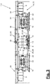
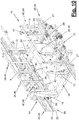
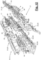
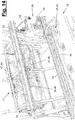
- Figures 11 to 14 show a variant of the processing station (2) which has a discharge device (58) and which, if necessary, manages without external storage spaces (20). They also show a different design and arrangement of the media coupling (47).
- Figure 12 are to The right frame magazines (18, 19) are not shown for a better overview.
- the detailed representation of Figure 13 is also one-sided and abstract.
- Figures 11 to 14 show the details of the individual conveying means (29) with the tow bar (55) together with the drive (56) and guide way (30) and the individual towing vehicle (35) with guide way (36).
- the guideways (30,36) are each arranged separately from the conveyor tracks (26,32), which in turn are used as individual rails (27,33) for the frame-side drives (28) with fork arms (52) and support rollers (53,54) are trained.
- the positioning device (11) is equipped with the positioning elements (41-43) and fixing means (44) described above.
- the discharge device (58) is used for the introduction and discharge of clamping frames (6-9) and can be present one or more times. It can connect to one or both conveyor tracks (26) at one or both front ends. As an alternative or in addition, it can interact with the return conveyor track.
- the discharge device (58) has a movable and preferably controllably driven discharge path (59), e.g. in the form of a rail section, which is aligned on the one hand for the transport of the tenter with the conveyor track (26, 32) and on the other hand in an e.g. inclined change position to a mobile discharge carriage (60 ) can be moved, in particular pivoted.
- the discharge track (59) is pivotably arranged on the magazine frame (22) by means of a link mechanism and can thus saving space between the in Figure 11 Pivot shown positions.
- the discharge carriage (60) can dock on the discharge path (59) in the inclined pivoting position. It is preferably floor-bound and height-adjustable. It also has a track or rail section for receiving a clamping frame (6-9) or its drive (28). It can be driven manually movable or controllable.
- the drive width is smaller than the clamping frame width.
- the rail sections of the discharge device (58) can therefore be short and space-saving. The same applies to the feed device (13) described above and its track or rail section.
- the media couplings (47) are designed and arranged differently in the variant.
- the coupling elements (48, 49) are separated from the mechanical stakes and are arranged centrally on the clamping frames (6-9) and on the magazine locations of the frame magazines (16-19).
- the coupling elements (48, 49) are each located on an arm of the clamping frame (6-9) and the magazine locations.
- the frame magazines (16-19) can have a different design and arrangement. They can be designed, for example, as turntables with several magazine locations and an upright or standing axis of rotation, for example according to the EP 1 858 750 B1 . An even number of is also recommended for such a magazine training Magazine places.
- frame magazines (16-19), frame conveyors (25) and frame transporters (31) as well as delivery and positioning devices (11, 13) can only be arranged on one side of the transfer line (5).
- frame magazines (16-19) shown in pairs it is possible to choose a different magazine arrangement on both sides of the workstation (10) between them. In this case, for example, only one frame magazine can be assigned to a work station (10). On the other hand, the number of frame magazines assigned to a job (10) on one side can also be greater than two.
- the clamping frames (6-9) can be held and supported on a conveyor (29,35), for example being loaded and unloaded with a suitable feeding device.
- the clamping frames (6-9) are then no longer guided independently, so that the respective conveyor track (26, 32) is possibly reduced to the guide track (30, 36) of the frame conveyor (25) and / or frame transporter (31).
- the frame conveyor (25) and the frame transporter (31) can be arranged at the same height relative to the respectively connected frame magazine (s) (16-19). This can be the case, for example, with a magazine design in the form of turntables or upright columns.
Landscapes
- Engineering & Computer Science (AREA)
- Mechanical Engineering (AREA)
- Combustion & Propulsion (AREA)
- Manufacturing & Machinery (AREA)
- Chemical & Material Sciences (AREA)
- Transportation (AREA)
- Optics & Photonics (AREA)
- Physics & Mathematics (AREA)
- Automatic Assembly (AREA)
- Automobile Manufacture Line, Endless Track Vehicle, Trailer (AREA)
- Specific Conveyance Elements (AREA)
- Treatment Of Fiber Materials (AREA)
- Intermediate Stations On Conveyors (AREA)
- Tyre Moulding (AREA)
Description
- Die Erfindung betrifft eine Wechselvorrichtung und ein Wechselverfahren für Spannrahmen mit den Merkmalen im Oberbegriff des Verfahrens- und Vorrichtungshauptanspruchs.
- Ein solche Wechselvorrichtung für Spannrahmen an einer Fügestation von Karosserieteilen ist aus der
WO 2014/026475 A bekannt. Die Wechselvorrichtung weist trommelartige Rahmenmagazinen und einen Rahmenförderer für den Transport der Spannrahmen zwischen den Rahmenmagazinen und einer Arbeitsstelle der Bearbeitungsstation sowie einen weiteren Rahmentransporter auf, der ebenfalls mit den vom Rahmenförderer bedienten Rahmenmagazinen verbunden ist. Die Spannrahmen sind mit ihren Laufwerken lose und rollfähig an Schienenstücken der Rahmenmagazine gehalten. - Die
EP 1 858 750 B1 zeigt eine andere Wechselvorrichtung an einer Fügestation für Karosserieteile, die mehrere gesteuert drehbare Rahmenmagazine mit aufrechter Drehachse und nur einen Rahmenförderer aufweist, der die Spannrahmen zwischen den Magazinen und zu einer Arbeitsstelle der Fügestation transportiert. - Es ist Aufgabe der vorliegenden Erfindung, eine weiterverbesserte Spannrahmenlogistik aufzuzeigen.
- Die Erfindung löst diese Aufgabe mit den Merkmalen im Verfahrens- und Vorrichtungshauptanspruch.
- Die beanspruchte Wechseltechnik, insbesondere die Wechselvorrichtung und das Wechselverfahren, bieten eine gesteigerte Flexiblität für den Einsatz und den Wechsel von unterschiedlichen, typspezifischen Spannrahmen. Zudem können bei einem Wechsel des Karosserietyps und der jeweiligen Karosserieteile die Spannrahmen schnell ausgetauscht werden. Ferner kann die Zahl der verfügbaren unterschiedlichen Spannrahmen bzw. Spannrahmentypen gesteigert werden. Trotz erhöhter Spannrahmenzahl ist dabei eine kurzeitige Verfügbarkeit des jeweils benötigten Spannrahmens gewährleistet.
- Die Spannrahmen werden in mehreren Rahmenmagazinen temporär gespeichert, in denen sie gesichert aufgenommen werden können. Dies ist bei einer liegenden Rahmenaufnahme in einem Trommelmagazin von Vorteil und kann auch für eine Eigenstabilität des Spannrahmens und seiner Komponenten sowie eine Identifizierbarkeit sorgen. Die gesicherte Aufnahme wird durch eine gesteuerte Verriegelungseinrichtung und eine Medienkupplung erreicht. Die Verriegelungseinrichtung fixiert den jeweiligen Spannrahmen in der Aufnahmeposition und gibt ihn für den Rahmenwechsel wieder frei. Mittels der Verriegelungseinrichtung wird außerdem die Medienkupplung automatisch geöffnet oder geschlossen. Mittels der Medienkupplung können Betriebsmittel, insbesondere Fluide, und Daten zwischen dem Rahmenmagazin und dem jeweiligen Spannrahmen übertragen werden.
- Der Rahmenförderer und der zugeordnete Rahmentransporter bieten mehrere parallele Verbindungsmöglichkeiten für die zugehörigen Rahmenmagazine. Der Rahmenförderer verbindet die Rahmenmagazine mit der Arbeitsstelle. Er kann auch beim Rahmenwechsel zwei Spannrahmen gleichzeitig transportieren. Er kann dabei den bisherigen Spannrahmen abführen und den neuen Spannrahmen zuführen. Der bevorzugt parallel zugeordnete Rahmentransporter erlaubt unabhängig vom Rahmenförderer einen Wechsel von Spannrahmen zwischen verschiedenen Rahmenmagazinen. Hierdurch kann ein Rückfluss, insbesondere ein Kreislauf, der Spannrahmen zwischen den Rahmenmagazinen erreicht werden.
- Der Förderbetrieb des Rahmentransporters kann unabhängig und zeitgleich mit dem Förderbetrieb des Rahmenförderers stattfinden. Hierdurch können einerseits Magazinüberfüllungen vermieden werden. Andererseits können auf einfache Weise leere Magazinplätze gebildet werden, die für einen vom Rahmenförderer durchgeführten Spannrahmenwechsel nützlich oder erforderlich sind. Im Weiteren können auch unnötige Leerfahrten des Rahmenförderers vermieden werden.
- Der Parallelbetrieb von Rahmenförderer und Rahmentransporter verkürzt signifikant die Wechselzeiten für einen Spannrahmen. Nützlich ist hierfür eine gerade Zahl von Magazinplätzen an den Rahmenmagazinen.
- Ein weiterer Vorteil ist die Generierung zusätzlicher, zumindest temporärer Speicherplätze für Spannrahmen. Auf der Förderbahn des Rahmentransporters kann z.B. mindestens ein solcher temporärer Speicherplatz zwischen den Rahmenmagazinen gebildet werden. Ferner können auch auf andere Weise neben den Rahmenmagazinen zusätzliche Speicherplätze generiert werden. Dies ist insbesondere durch eine über ein Rahmenmagazin hinaus verlängerte Förderbahn des Rahmentransporters möglich.
- Vorteilhafterweise werden die Spannrahmen beim Transport an einer Führungsbahn mit einer einzelnen Schiene kippsicher geführt. Das Fördermittel, bevorzugt ein Schleppholm, wird parallel dazu und getrennt geführt. Dies spart Platz sowie Bauaufwand und bietet eine vereinfachte, hochflexible, extrem schnelle sowie kostengünstige Fördertechnik.
- An der Arbeitsstelle können die Spannrahmen von einer Zustellvorrichtung zugestellt und mit einer Positioniereinrichtung an einem Gestell in allen drei Raumrichtungen x, y, z bzw. Raumachsen exakt stationär positioniert und fixiert werden. Eine Positionierung durch mehrere Rollböcke und ein Schwert ist besonders effektiv sowie betriebssicher und bietet auch unter schwierigen Umgebungs- und Prozessbedingungen, insbesondere beim Schweißen, eine zuverlässige und exakte Positionierung mit hoher Wiederholgenauigkeit.
- Mittels einer Ausschleuseinrichtung der Wechselvorrichtung können bedarfsweise Spannrahmen aus der Bearbeitungsstation entnommen und zugeführt werden. Dies ist z.B. für Wartungszwecke oder für eine schnelle Umrüstung von Vorteil.
- In den Unteransprüchen sind weitere vorteilhafte Ausgestaltungen der Erfindung angegeben.
- Die Erfindung ist in den Zeichnungen beispielsweise und schematisch dargestellt. Im Einzelnen zeigen:
- Figur 1:
- eine perspektivische Ansicht einer Bearbeitungsstation mit einer Wechselvorrichtung,
- Figur 2:
- eine Draufsicht auf die Bearbeitungsstation gemäß Pfeil II von
Figur 1 , - Figur 3:
- eine Seitenansicht der Bearbeitungsstation gemäß Pfeil III von
Figur 1 , - Figur 4:
- eine Stirnansicht der Bearbeitungsstation gemäß Pfeil IV von
Figur 1 , - Figur 5:
- eine andere perspektivische Ansicht der Bearbeitungsstation von
Figur 1 bis 4 , - Figur 6:
- eine abgebrochene und vergrößerte Detaildarstellung von
Figur 3 , - Figur 7:
- eine abgebrochene, abstrahierte und vergrößerte Detaildarstellung von
Figur 1 , - Figur 8:
- eine weiter vergrößerte Detaildarstellung von
Figur 7 , - Figur 9:
- eine vergrößerte Draufsicht der Arbeitsstelle gemäß
Figur 2 , - Figur 10:
- eine perspektivische Ansicht der Arbeitsstelle gemäß
Figur 9 , - Figur 11:
- eine Variante der Wechselvorrichtung von
Figur 1 bis 10 in Draufsicht, - Figur 12:
- eine perspektivische und einseitig abstrahierte Ansicht der Variante von
Figur 11 , - Figur 13:
- eine vergrößerte perspektivische Detaildarstellung zu
Figur 12 und - Figur 14:
- eine vergrößerte perspektivische Detaildarstellung eines Rahmenmagazins gemäß
Figur 11 bis 13 . - Die Erfindung betrifft eine Wechselvorrichtung (14) für Spannrahmen (6-9) und ein Wechselverfahren. Die Erfindung betrifft ferner eine mit einer solchen Wechselvorrichtung (14) ausgestattete Bearbeitungsstation (2) und im Weiteren auch eine mit einer oder mehreren solcher, ggf. verketteter Bearbeitungsstationen (2) ausgestattete Bearbeitungsanlage (1).
- Die Bearbeitungsstation (2) ist bevorzugt als Fügestation, insbesondere als sogenannte Geostation oder Framingstation für das Fügen von Werkstücken (4) ausgebildet. Die Werkstücke (4) sind bevorzugt als Karosserieteile, insbesondere Blechteile, einer Fahrzeugrohkarosserie ausgebildet. Es kann sich z.B. um eine Bodengruppe und linke und rechte Seitenwände handeln, die in der Fügestation (2) in eine vorgegebene Relativlage zueinander gebracht, in dieser Lage gespannt und dann gefügt werden, z.B. durch Schweißen. In der Geostation (2) kann der Karosserieteilverbund zunächst geheftet und in einer nachfolgenden weiteren Fügestation ausgeschweißt werden. Diese kann entsprechend der Geostation ausgebildet sein. Die Karosserieteile (4) werden auf einer Transferlinie (5) der Fügestation (2) zugeführt, wobei sie selbsttragend oder mittels einer Palette oder eines anderen Trägers auf einem Förderer, z.B. einem Hubshuttle, einem Skidförderer oder dgl. entlang der Transferlinie (5) transportiert werden. Die Transferlinie (5) kann eine Reihe von Stationen (2) verketten.
- Die Karosserieteile (4), insbesondere die Bodengruppe und die Seitenwände können z.B. in einer vorpositionierten und lose vorgefügten, insbesondere geklammerten Zuordnung zugeführt werden. In einer anderen Variante kann eine Bodengruppe auf der Transferlinie (5) zugeführt werden, wobei die Seitenwände getrennt davon an der Fügestation (2) zugeführt werden.
- Die Fügestation (2) weist eine Arbeitsstelle (10) auf, an der ein oder mehrere Bearbeitungsvorrichtungen (3) für die Durchführung des Bearbeitungsprozesses angeordnet sind. Sie sind beidseits der Transferlinie (5) angeordnet und bevorzugt als Industrieroboter mit einem geeigneten Fügewerkzeug, z.B. einem Schweißwerkzeug, ausgebildet. In
Figur 2 ist ein Industrieroboter bzw. Schweißroboter (3) schematisch angedeutet. Je nach Art des Bearbeitungsprozesses können die Industrieroboter auch andere Werkzeuge tragen. - Die Karosserieteile (4) und/oder ihr Träger werden an der Arbeitsstelle (10) mittels eines in
Figur 2 ,9 und10 schematisch angedeuteten Vorpositionierers (39) in eine exakte, vorgegebene Stellung gebracht. - Das Positionieren, gegenseitige Ausrichten und Spannen der zu fügenden Karosserieteile (4) wird mittels Spannrahmen (6-9) durchgeführt, die mittels einer Zustellvorrichtung (13) an der Arbeitsstelle (10) beidseits an die Transferlinie (5) und die dort befindlichen Karosserieteile (4) zugestellt werden. Von den Spannrahmen (6-9) können ggf. auch Karosserieteile (4) an die Arbeitsstelle (10) zugeführt werden.
- Die Spannrahmen (6-9) bestehen aus einem platten- oder rahmenförmigen Träger und daran angeordneten Spannmitteln sowie Positionier- und Stützmitteln für die Karosserieteile (4). Außerdem können weitere Komponenten, wie z.B. Hilfswerkzeuge etc. angebaut werden. Ein Spannrahmen (6-9) kann in geeigneter Weise mit Betriebsmitteln oder Medien versorgt werden. Dies können elektrische Signal- und Leistungsströme, Fluide, insbesondere Druckluft, Kühlmittel, Hydrauliköl oder dgl. sein. Die Spann-, Positionier- und Stützmittel können z.B. elektromechanisch oder fluidisch, insbesondere pneumatisch, betätigt und bewegt werden.
- Die Spannrahmen (6-9) werden an der Arbeitsstelle (10) beidseits der Transferlinie (5) exakt positioniert und stationär aufgenommen. Hierfür weist die Fügestation (2) gemäß
Figur 2 ,9 und10 ein Gestell (12) mit z.B. mehreren, insbesondere vier, aufrechten Eckpfosten auf, an denen die Spannrahmen (6-9) mittels einer Positioniereinrichtung (11) in vorgegebener Lage und in Spannposition relativ zu den Karosserieteilen (4) aufgenommen und fixiert werden. Hierbei kann auch eine Medienversorgung mittels geeigneter Medienkupplungen (47) stattfinden. - Die Positioniereinrichtung (11) ist auf einer oder beiden Seiten der Transferlinie (5) angeordnet. Sie wirkt mit der jeweiligen Zustellvorrichtung (13) bei deren Zustellbewegung bzw. Quervorschub zusammen. In der Darstellung von
Figur 2 ,9 und10 befindet sich der eine Spannrahmen (6) in der Spannposition an der Arbeitsstelle (10). Der andere Spannrahmen (8) nimmt eine Warteposition vor dem Quervorschub ein. - Wie
Figur 2 ,9 und10 verdeutlichen, weist die Positioniereinrichtung (11) mehrere Positionierelemente (40,41,42) auf, die den Spannrahmen (6-9) aufnehmen, abstützen und in den drei Raumrichtungen x, y und z exakt positionieren. Am Gestell (12), insbesondere an den Eckpfosten, sind steuerbare Fixiermittel (44), z.B. Spanner, angeordnet, die den Spannrahmen (6-9) in der eingenommenen exakten Position festhalten und auch gegen Bearbeitungs- und Reaktionskräfte abstützen. - Die Positionierelemente (40,41,42) sind z.B. jeweils als drei längs der Transferlinie (5) aufgereihte flurgebundene Rollenböcke ausgebildet, auf denen der Spannrahmen (6-9) beim besagten Quervorschub aufgleitet und mittels der Rollen positioniert wird. Die beiden äußeren Rollenböcke (40,42) positionieren ihn dabei mit aufrechten Rollen in der vertikalen z-Richtung. Das liegende Rollenpaar des mittleren Rollenbocks (41) positioniert mit einer Anschlagfunktion quer zur Transferlinie (5) in der y-Richtung. Ein am Spannrahmen (6-9) angeordnetes Positionierelement (43), z.B. ein Schwert, greift beim Quervorschub zwischen die Rollen des Paars, wodurch der Spannrahmen (6-9) in der x-Richtung längs der Transferlinie (5) positioniert wird. Alternativ können die Positionierelemente (40,41,42) als Gleitböcke oder in anderer Weise ausgebildet sein.
- Die Ausbildung der Spannrahmen (6-9) und der anderen vorgenannten Stationskomponenten für die Durchführung des Bearbeitungsprozesses, insbesondere Fügeprozesses, können andererseits die gleichen wie in der
EP 1 858 750 B1 sein. - In der Bearbeitungsstation (2), insbesondere Fügestation ist eine Wechselvorrichtung (14) für die Spannrahmen (6-9) angeordnet. In der Bearbeitungsanlage (1) und der Bearbeitungsstation (2) können verschiedene Karosserieteile (4) in einem freien Mix zugeführt und bearbeitet werden. Die Unterschiede können verschiedene Karosserietypen einer Fahrzeugbaureihe, z.B. Karosserien für eine Limousine, ein Cabriolet oder dergleichen betreffen. Dementsprechend ändern sich die Seitenwände (4) und damit die hierauf adaptierten Spannrahmen (6-9). Bei einem Typwechsel werden auch die Spannrahmen (6-9) getauscht.
- Die Wechselvorrichtung (14) weist eine Speichereinrichtung (15) für die verschiedenen Spannrahmen (6-9) und einen Rahmenförderer (25) sowie einen Rahmentransporter (31) auf. Die Speichereinrichtung (15) weist mehrere gesteuert bewegliche Rahmenmagazine (16-19) auf, wobei an jedem Rahmenmagazin (16-19) mehrere Spannrahmen (6-9) lösbar angeordnet sind.
- In den gezeigten Ausführungsbeispielen sind die Rahmenmagazine (16-19) für die Spannrahmen (6-9) beidseits der Transferlinie (5) angeordnet. Dies kann eine mittensymmetrische Anordnung bezüglich der zentralen Transferlinie (5) sein.
- Die Wechselvorrichtung (14) weist eine nicht dargestellte Steuerung auf, an welche die Rahmenmagazine (16-19) und die Fördereinrichtungen (25,31) sowie die Zustellvorrichtungen (13) nebst Positioniereinrichtungen (11) und ggf. weitere nachgenannte steuerbare Komponenten angeschlossen sind. Diese Steuerung kann an eine übergeordnete Stationssteuerung angeschlossen oder in diese integriert sein.
- Die Rahmenmagazine (16,17 und 18,19) sind jeweils in Transferrichtung (5) gesehen mit gegenseitigem Abstand und zu beiden Seiten der Arbeitsstelle (10) angeordnet. Die gezeigte Speichereinrichtung (15) hat vier Rahmenmagazine (16-19) in verteilter Anordnung. Sie kann außerdem einen oder mehrere zusätzliche Speicherplätze (20) für einen oder mehrere Spannrahmen (6,9) aufweisen. Hierauf wird später noch näher eingegangen.
- Die Rahmenmagazine (16-19) sind in den gezeigten Ausführungsbeispielen als Trommelmagazine ausgebildet, die um eine liegende bzw. horizontale Drehachse (21) drehbar an einem Magazingestell (22) angeordnet sind. Die Rahmenmagazine (16-19) haben mehrere Magazinplätze für die Aufnahme jeweils eines Spannrahmens (6-9). Die Drehachse (21), die Magazinplätze und die Rahmenaufnahmen sind bevorzugt längs der Transferlinie (5) ausgerichtet. Vorzugsweise ist die Zahl der Magazinplätze gerade. In den gezeigten Ausführungsbeispielen sind jeweils vier Magazinplätze vorhanden.
- Der Rahmenförderer (25) ist für den Transport der Spannrahmen (6-9) zwischen den jeweils zugeordneten Rahmenmagazinen (16-19) und der Arbeitsstelle (10) vorgesehen. Der Rahmenförderer (25) ist dabei zwischen den entlang der Transferlinie (5) angeordneten und aufgereihten Rahmenmagazinen (16,17 und 18,19) und der Transferlinie (5) angeordnet. Er ist dabei auch neben dem Stationsgestell (12) angeordnet, z.B. mit seitlichem Abstand. Die Förderrichtung des Rahmenförderers (25) ist ebenfalls entlang der Transferlinie (5), insbesondere parallel dazu ausgerichtet. Die besagte Anordnung ist einseitig oder beidseits der Transferlinie (5) vorhanden und parallel dazu ausgerichtet.
- Der Rahmenförderer (25) weist eine Förderbahn (26) und ein angetriebenes sowie steuerbares Fördermittel (29) auf. Die Förderbahn (26) kann mehrteilig sein. Sie kann dabei Führungsmittel (27,28) für die eigenständige Abstützung und Führung der Spannrahmen (6-9) sowie ggf. eine getrennte Führungsbahn (30) für das Fördermittel (29) aufweisen. Die Führungsmittel (27,28) können z.B. als stationäre Schienenanordnung (27) und als jeweils an einem Spannrahmen (6-9) angeordnetes gleitendes oder rollendes Laufwerk (28) ausgebildet sein. Die Zuordnung und Kinematik kann auch umgekehrt sein. Die Führungsbahn (30) kann ebenfalls als Schienenführung ausgebildet sein.
- Der Rahmenförderer (25) kann einen neuen Spannrahmen (6,8) von einem Rahmenmagazin (16-19) oder einem Speicherplatz (20) abholen, an den Bereich der Arbeitsstelle (10) zuführen und im Wechsel einen bisher benutzten Spannrahmen (6,8) übernehmen sowie dem gleichen oder bevorzugt einem anderen Rahmenmagazin (16-19) oder Speicherplatz (20) zuführen. Der Rahmenförderer (25) kann hierfür ggf. zumindest temporär mehrere Spannrahmen (6-9) zugleich bewegen.
- Ein Rahmenförderer (25) kann ein oder mehrere Fördermittel (29) aufweisen. Der in
Figur 1 ,5 und7 gezeigte Rahmenförderer (25) besitzt ein einzelnes Fördermittel (29) mit einem Holm (55), insbesondere Schleppholm, der an oder auf der Führungsbahn (30) geführt und von einem steuerbaren, bevorzugt stationären Antrieb (56) reversierend angetrieben ist. Der Antrieb (56) weist z.B. einen Elektromotor auf, der über einen Zahnstangentrieb oder dgl. den Holm (55) vorwärts und rückwärts bewegt. Die Führungsbahn (30) ist z.B. als stationäre Schiene ausgebildet, auf oder an welcher der z.B. im Querschnitt U-förmige Holm (55) mittels Roll- oder Gleitmitteln reibungsarm geführt ist. - Der Holm (55) ragt über etwas mehr als die halbe Länge der Station (2) und trägt eine Kupplungseinrichtung (37) für zwei Spannrahmen (6-9). Diese besteht z.B. aus zwei axial distanzierten, steuerbaren Mitnehmern (57), die mit einem Spannrahmen (6-9) in der Warteposition an der Arbeitsstelle (10) und mit einem anderen zum Wechsel bereit stehenden Spannrahmen (6-9) in einem Rahmenmagazin (16-19) in Schleppeingriff treten können.
- Mit einer einzigen Fahrbewegung des Schleppholms (55) kann dadurch beim Spannrahmenwechsel der nicht mehr benötigte Spannrahmen (6-9) von der Warteposition in ein Rahmenmagazin (16-19) geschafft und eine neuer Spannrahmen (6-9) aus einem anderen Rahmenmagazin (16-19) in die Warteposition an der Arbeitsstelle (10) gebracht werden. Ein Spannrahmenwechsel ist dabei in beiden Richtungen längs der Transferlinie (5) möglich, wobei die Wechselrichtung frei gewählt werden kann.
-
Figur 7 zeigt diese Eingriffstellung mit den Spannrahmen (8,9) auf der rechten Stationsseite vor dem Förderhub des Holms (55), bei dem dann der zu wechselnde Spannrahmen (8) in das Rahmenmagazin (19) gebracht und ein neuer Spannrahmen (9) aus dem Rahmenmagazin (17) zugeführt wird. Die Rahmenmagazine (17,19) sind aus Gründen der Übersichtlichkeit nicht dargestellt. - Bei einer alternativen Mehrfachanordnung von Fördermitteln (29) sind z.B. zwei Fördermittel (29) vorhanden, die eigenständig angetrieben und gesteuert sind sowie getrennt voneinander auf einer bevorzugt gemeinsamen Führungsbahn (30) fahren können. Das oder die Fördermittel (29) können z.B. als Schleppwagen ausgebildet sein.
- Die in
Figur 1 bis 10 gezeigte Förderbahn (26) weist eine einzelne Schiene (27) für den geführten stehenden Transport der Spannrahmen (6-9) auf. Die Schiene (27) besitzt obere und untere bevorzugt U-förmige Führungsspuren (50,51), in oder an denen jeweils vertikale und horizontale Stützrollen (53,54) des Laufwerks (28) laufen. Das Laufwerk (28) besitzt zwei oder mehr vom Spannrahmen (6-9) abstehende Stützarme (52), welche die Schiene (27) gabelartig seitlich umgreifen und obere und untere Paarungen von Stützrollen (53,54) tragen. Diese Spuren- und Rollenanordnung ermöglicht eine platzsparende und kippsichere Spannrahmenführung. Alternativ können die zwei oder mehr Führungsspuren (50,51) in anderer Weise ausgebildet und/oder angeordnet sein, z.B. seitlich oder über Eck. - Für den Quertransport der Spannrahmen (6-9) vom Rahmenförderer (25) zum Stationsgestell (12) sowie der dortigen Arbeitsstelle (10) und zurück ist eine steuerbare und angetriebene Zustellvorrichtung (13) vorgesehen. Sie nimmt einen Spannrahmen (6,8) vom Rahmenförderer (25) ab und transportiert ihn zum Stationsgestell (12) sowie der dortigen Positioniereinrichtung (11). Die Zustellvorrichtung (13) bringt zuvor den bisher benutzten Spannrahmen (6,8) zurück zum Rahmenförderer (25). Dieser kann den gewechselten Spannrahmen (6,8) dann weiter zum anderen Rahmenmagazin transportieren.
- Wie
Figur 2 ,4 ,9 und10 verdeutlichen, weist die Zustellvorrichtung (13) einen quer zur Transferlinie (5) verfahrbaren Schlitten mit einem steuerbaren Antrieb und mit einem Bahn- oder Schienenstück zur Aufnahme eines stehenden Spannrahmens (6-9) mit seinem Laufwerk (28) auf. Das bevorzugt einzelne Bahn- oder Schienenstück kann in eine Lücke der Schiene (27) eingepasst werden. Es hat ausreichend Führungsspiel für die Stützrollen (53,54), um die Positionierbewegung an der Positioniereinrichtung (11) und ihren Positionierelementen (40-43) zu ermöglichen. - Die Wechselvorrichtung (14) weist den genannten weiteren Rahmentransporter (31) auf, der ebenfalls mit den vom Rahmenförderer (25) bedienten Rahmenmagazinen (16-19) verbunden ist. In der gezeigten Ausführungsform der Wechselvorrichtung (14) ist beidseits der Transferlinie (5) jeweils ein Rahmentransporter (31) angeordnet. Der eine Rahmentransporter (31) ist mit den Rahmenmagazinen (16,17) auf der einen Seite der Transferlinie (5) verbunden. Auf der anderen Seite ist der Rahmentransporter (31) mit den Rahmenmagazinen (18,19) verbunden.
- Der Rahmenförderer (25) und der jeweils zugeordnete Rahmentransporter (31) sind an unterschiedlichen Seiten der gemeinsam bedienten Rahmenmagazine (16-19) angeordnet. Der Rahmenförderer (25) befindet sich z.B. an der zur Transferlinie (5) weisenden Vorderseite und der Rahmentransporter (31) an der gegenüberliegenden Rückseite der jeweiligen Rahmenmagazine (16-19). Der Rahmentransporter (31) kann alternativ an der Oberseite oder der Unterseite der jeweiligen Rahmenmagazine (16-19) angeordnet sein. In weiterer Abwandlung können mehrere Rahmentransporter (31) einer Magazinreihe und einem Rahmenförderer (25) zugeordnet sein.
- Der Rahmentransporter (31) weist ebenfalls eine Förderbahn (32) und ein angetriebenes, steuerbares Fördermittel (35) auf. Die Förderbahn (32) erstreckt sich entlang der Transferlinie (5). Sie kann ebenfalls mehrteilig sein, indem sie eigenständige Führungsmittel (33,34) für die Spannrahmen (6-9) und eine Führungsbahn (36) für das Fördermittel (35) aufweist. Die Führungsmittel (33,34) können als Schienenanordnung und als Laufwerk für die Spannrahmen (6-9) ausgebildet sein. Als Laufwerk (34) kann ggf. das vorhandene Laufwerk (28) vom Rahmenförderer (25) oder ein zusätzliches Laufwerk benutzt werden, das evtl. anders ausgebildet und an anderer Spannrahmenstelle angeordnet ist. Die Führungsbahn (36) kann als Schienenführung und ggf. in der vorbeschriebenen Art mit Führungsspuren (50,51) gestaltet sein. Das steuerbare Fördermittel (35) ist z.B. als Schleppwagen ausgebildet. Es kann einzeln oder mehrfach vorhanden sein, wobei z.B. ein oder zwei Schleppwagen auf der Führungsbahn (36) verkehren.
- Die Fördermittel (29,35) können jeweils eine steuerbare Kupplungseinrichtung (37) zum An- und Abkuppeln von einem oder mehreren Spannrahmen (6-9) aufweisen. Die Kupplungseinrichtung (37) arbeitet vorzugsweise mit Formschluss. Beim Schleppholm (55) wird die Kupplungseinrichtung (37) von den beiden Mitnehmern (57) gebildet. Durch die getrennte Führung von Spannrahmen (6-9) und Fördermitteln (29,35) können sich letztere unabhängig von den Spannrahmen (6-9) entlang ihrer jeweiligen Förderbahn (26,32) bzw. Führungsbahn (30,36) bewegen.
- Der oder die Rahmenförderer (25) und der oder die Rahmentransporter (31) können konstruktiv in ähnlicher Weise ausgebildet sein. Sie können sich alternativ unterscheiden. Am Ende der Beschreibung sind hierzu konstruktive Abwandlungsmöglichkeiten angegeben.
- Die Förderbahnen (26,32) des Rahmenförderers (25) und des jeweils zugeordneten Rahmentransporters (31) sind in unterschiedlicher Höhe an ein Rahmenmagazin (16-19) angebunden. Die Förderbahn (26) ist z.B. an der Unterseite der Rahmenmagazine (16-19) und die Förderbahn (32) an der Oberseite der Rahmenmagazine (16-19) angebunden. Dies ist besonders vorteilhaft bei der gezeigten Magazinausbildung als liegend angeordnete Trommelmagazine.
- Der Rahmenförderer (25) ist bei dem gezeigten und bevorzugten Ausführungsbeispielen als bodenseitiger Förderer ausgebildet, wobei die Spannrahmen (6-9) auf der Förderbahn (26) stehend transportiert werden und dort oder an der Oberseite in geeigneter Weise geführt sind. Der Rahmentransporter (31) ist als hochliegender Hängeförderer ausgebildet, wobei die Spannrahmen (6-9) an der Förderbahn (32) hängend transportiert werden. Die gezeigte Anordnung kann auch umgedreht sein.
- Die Übergabe der Spannrahmen (6-9) von den Fördereinrichtungen (25,31) an die Rahmenmagazine (16-19) und zurück kann in beliebig geeigneter Weise bewirkt werden. An den Magazinplätzen ist hierfür z.B. jeweils ein Rahmenhalter (23), z.B. eine formschlüssig aufnehmende Stützschiene, vorhanden, die je nach Drehstellung des Rahmenmagazins (16-19) mit der Förderbahn (26), insbesondere der Schiene (27), des Rahmenförderers (25) und der Förderbahn (32), insbesondere der Schiene (33), des Rahmentransporters (31) fluchtet und ein Einschieben des Spannrahmens (6,9), z.B. seines Laufwerks (28,34), erlaubt.
- Der Rahmenhalter (23) und die Förderbahn (26) haben eine übereinstimmende Form, insbesondere Schienenform mit Führungsspuren (50,51). An den Rahmenmagazinen (16-19) können steuerbare Schienenfixierungen (38) zur Positionierung und Sicherung der fluchtenden Stellung von Rahmenhalter (23) und Förderbahn (26) angeordnet sein.
- Die Rahmenmagazine (16-19) weisen ferner an den Magazinplätzen jeweils eine steuerbare Verriegelungseinrichtung (24) auf, die den aufgenommenen Spannrahmen (6-9) zusätzlich fixiert und für einen Abtransport wieder freigibt. Der Spannrahmen (6-9) kann insbesondere in liegender Position gesichert und lagetreu gehalten werden. Zudem wird die Übergabe- und Übernahmeposition gegenüber der Förderbahn (26,32) definiert.
- Die in
Figur 4 ,7 und8 gezeigte Verriegelungseinrichtung (24) wird von Riegelelementen (45,46) am Rahmenmagazin (16-19) und am Spannrahmen (6-9) gebildet, die formschlüssig ineinander greifen können. Die Riegelelemente (45) am Rahmenmagazin (16-19) sind steuerbar angetrieben. Sie können den Spannrahmen (6-9) bei der Verriegelung ggf. ein Stück bewegen. Die Riegelelemente (45) sind z.B. als schwenkbare Greifer ausgebildet. Diese treten mit bolzen- oder rollenförmigen Riegelelementen (46) am Spannrahmen (6-9) in Eingriff, die dort z.B. an quer abstehenden Auslegern angeordnet sind. Die Anordnung kann auch umgedreht sein. - Ferner sind Medienkupplungen (47) an den Magazinplätzen zwischen den Rahmenmagazinen (16-19) und den aufgenommenen Spannrahmen (6-9) vorhanden. Sie bestehen z.B. jeweils aus einem Kupplungselement (48) am Magazinplatz und einem Kupplungselement (49) am Spannrahmen (6-9), die einzeln oder mehrfach vorhanden und randseitig angeordnet sind. Die Kupplungselemente (48,49) können außerdem als mechanische Absteckung für die Spannrahmen (6-9) am Magazinplatz dienen.
- Die Medienkupplungen (47) können Betriebsmittel, z.B. Fluide, Leistungs- und/oder Signalströme, übertragen. Dadurch können bewegliche Spann-, Positionier- und Stützmittel der Spannrahmen (6-9) aktiviert und in ihrer Soll-Position arretiert und gesichert werden. Dies verhindert unkontrollierte Eigenbewegungen und hieraus resultierende Kollisionsgefahren, insbesondere bei einer liegenden Spannrahmenlage am Rahmenmagazin (16-19). Über die Signalströme oder auf andere Weise können Daten ausgetauscht werde. Dies ist zu Steuer- und Identifizierungszwecken von Vorteil. Die Steuerung weiß stets, wo sich welcher Spannrahmen (6-9) befindet.
- Die Medienkupplungen (47) werden in der Aufnahmeposition am Magazinplatz von der Verriegelungseinrichtung (24) bei deren Verriegelungsbewegung automatisch geöffnet und geschlossen.
- Die Speichereinrichtung (15) kann die vorerwähnten einen oder mehreren weiteren Speicherplätze (20) für einen oder mehrere Spannrahmen (6-9) aufweisen. In den gezeigten Ausführungsbeispielen erstrecken sich die Förderbahnen (26,32) über ein oder mehrere zugeordnete Rahmenmagazine (16-19) an einem oder beiden Enden hinaus. An diesem Bahnenüberstand wird jeweils ein solcher Speicherplatz (20) gebildet. Hier können jeweils ein oder mehrere Spannrahmen (6-9) außerhalb der Rahmenmagazine (16-19) geparkt werden.
- Solche Bahnüberstände und Speicherplätze (20) können an allen Förderbahnen (26,32) vorhanden sein. Falls es der Platzbedarf der Bearbeitungsanlage (1) und der Nachbarstation oder andere Gründe erfordern, kann die Zahl und Anordnung der Speicherplätze (20) reduziert werden. In den gezeigten Ausführungsbeispielen sind nur die Förderbahnen (32) der Rahmentransporter (31) beidendig zur Bildung von Speicherplätzen (20) verlängert.
- Ein oder mehrere weitere Speicherplätze (20) können auch an der Förderbahn (32) des Rahmentransporters (31) im Freiraum zwischen den längs der Transferlinie (5) beabstandeten jeweiligen Rahmenmagazinen (16,17,18,19) gebildet werden.
- Der Rahmentransporter (31) dient dem Rahmentausch zwischen den angeschlossenen Rahmenmagazinen (16-19) und ggf. den weiteren Speicherplätzen (20). Der Rahmentransporter (31) ist vorzugsweise nicht an die Arbeitsstelle (10) angebunden.
-
Figur 11 bis 14 zeigen eine Variante der Bearbeitungsstation (2), die eine Ausschleusvorrichtung (58) aufweist und die ggf. ohne äußere Speicherplätze (20) auskommt. Sie zeigen außerdem eine andere Ausbildung und Anordnung der Medienkuppplung (47). BeiFigur 12 sind zur besseren Übersicht die rechten Rahmenmagazine (18,19) nicht dargestellt. Die Detaildarstellung vonFigur 13 ist ebenfalls einseitig und abstrahiert. - Ansonsten kann die Variante mit den vorbeschriebenen Ausführungsbeispielen von
Figur 1 bis 10 übereinstimmen. Dies gilt insbesondere für die Gestaltung der Rahmenförderer (25) und Rahmentransporter (31) sowie der Positioniereinrichtung (11) und der Zustellvorrichtung (13).Figur 11 bis 14 zeigen hierzu die Details des einzelnen Fördermittels (29) mit dem Schleppholm (55) nebst Antrieb (56) und Führungsbahn (30) sowie des einzelnen Schleppwagens (35) mit Führungsbahn (36). Die Führungsbahnen (30,36) sind jeweils getrennt von den Förderbahnen (26,32) angeordnet, welche wiederum jeweils als einzelne Schienen (27,33) für die rahmenseitigen Laufwerke (28) mit Gabelarmen (52) und Stützrollen (53,54) ausgebildet sind. Die Positioniereinrichtung (11) ist mit den vorbeschriebenen Positionierelementen (41-43) und Fixiermitteln (44) ausgestattet. - Die Ausschleusvorrichtung (58) dient zum Ein- und Ausschleusen von Spannrahmen (6-9) und kann einfach oder mehrfach vorhanden sein. Sie kann an einer oder beiden Förderbahnen (26) an einem oder beiden Stirnenden anschließen. Sie kann alternativ oder zusätzlich mit der Rückführ-Förderbahn zusammenwirken.
- Die Ausschleusvorrichtung (58) besitzt eine bewegliche und bevorzugt steuerbar angetriebene Ausschleusbahn (59), z.B. in Form eines Schienenstücks, die einerseits zum Spannrahmentransport fluchtend mit der Förderbahn (26,32) ausgerichtet und andererseits in eine z.B. schräge Wechselposition zu einem mobilen Ausschleuswagen (60) bewegt, insbesondere geschwenkt, werden kann. Die Ausschleusbahn (59) ist mittels eines Lenkergetriebes schwenkbar am Magazingestell (22) angeordnet und kann dadurch platzsparend zwischen den in
Figur 11 gezeigten Positionen schwenken. - Der Ausschleuswagen (60) kann in der schrägen Schwenkstellung an der Ausschleusbahn (59) andocken. Er ist bevorzugt flurgebunden und höhenverstellbar. Er weist ebenfalls ein Bahn- oder Schienenstück zur Aufnahme eines Spannrahmens (6-9) bzw. seines Laufwerks (28) auf. Er kann manuell bewegbar oder steuerbar angetrieben sein.
- Die Laufwerksbreite ist kleiner als die Spannrahmenbreite. Die Schienenstücke der Ausschleusvorrichtung (58) können daher kurz und platzsparend ausgebildet sein. Entsprechendes gilt auch für die vorbeschriebene Zustellvorrichtung (13) und ihr Bahn- oder Schienenstück.
- Die Medienkupplungen (47) sind bei der Variante anders ausgebildet und angeordnet. Wie
Figur 13 und14 verdeutlichen, sind die Kupplungselemente (48,49) von den mechanischen Absteckungen getrennt und zentral an den Spannrahmen (6-9) und an den Magazinplätzen der Rahmenmagazine (16-19) angeordnet. Die Kupplungselemente (48,49) befinden sich dabei jeweils an einem Ausleger der Spannrahmen (6-9) und der Magazinplätze. - Abwandlungen der gezeigten und beschriebenen Ausführungsformen sind in verschiedener Weise möglich. Insbesondere können die Merkmale der Ausführungsbeispiele und der genannten Varianten in beliebiger Weise miteinander kombiniert und ggf. auch vertauscht werden.
- Die Rahmenmagazine (16-19) können eine andere Ausbildung und Anordnung haben. Sie können z.B. als Drehtische mit mehreren Magazinplätzen und einer aufrechten oder stehenden Drehachse ausgebildet sein, z.B. entsprechend der
EP 1 858 750 B1 . Auch bei einer solchen Magazinausbildung empfiehlt sich eine gerade Zahl von Magazinplätzen. - Ferner können in Abwandlung der gezeigten Ausführungsformen Rahmenmagazine (16-19), Rahmenförderer (25) und Rahmentransporter (31) sowie Zustell- und Positioniervorrichtung (11,13) nur an einer Seite der Transferlinie (5) angeordnet sein. Zudem ist es möglich, statt der gezeigten paarweisen Anordnung von Rahmenmagazinen (16-19) beidseits der zwischen ihnen liegenden Arbeitsstelle (10) eine andere Magazinanordnung zu wählen. Hierbei kann z.B. nur jeweils ein Rahmenmagazin einer Arbeitsstelle (10) zugeordnet sein. Andererseits kann die Zahl der einer Arbeitsstelle (10) an einer Seite zugeordneten Rahmenmagazine auch größer als zwei sein.
- Konstruktive Änderungen sind auch hinsichtlich des Rahmenförderers (25) und des Rahmentransporters (31) möglich. Die Spannrahmen (6-9) können auf oder an einem Fördermittel (29,35) gehalten und abgestützt sein, wobei sie z.B. mit einer geeigneten Zuführvorrichtung aufgeladen und abgeladen werden. Die Spannrahmen (6-9) sind dann nicht mehr eigenständig geführt, sodass die jeweilige Förderbahn (26,32) sich ggf. auf die Führungsbahn (30,36) des Rahmenförderers (25) und/oder Rahmentransporters (31) reduziert.
- Je nach Magazinausbildung können der Rahmenförderer (25) und der Rahmentransporter (31) in gleicher Höhe relativ zu dem oder den jeweils angebundenen Rahmenmagazinen (16-19) angeordnet sein. Dies kann z.B. bei einer Magazinausbildung in Form von Drehtischen oder aufrechten Säulen der Fall sein.
- Ein Einsatz ist ferner mit allen vorgenannten Varianten von Rahmenmagazinen (16-19) mit oder ohne Rahmentransporter (31) möglich.
- Die genannten Abwandlungen können ansonsten die gleiche oder entsprechende Ausbildung wie die gezeigten Ausführungsbeispiele haben.
-
- 1
- Bearbeitungsanlage
- 2
- Bearbeitungsstation, Fügestation, Geostation
- 3
- Bearbeitungsvorrichtung, Roboter
- 4
- Werkstück, Karosserieteil
- 5
- Transferlinie
- 6
- Spannrahmen
- 7
- Spannrahmen
- 8
- Spannrahmen
- 9
- Spannrahmen
- 10
- Arbeitsstelle
- 11
- Positioniereinrichtung
- 12
- Gestell
- 13
- Zustellvorrichtung
- 14
- Wechselvorrichtung für Spannrahmen
- 15
- Speichereinrichtung
- 16
- Rahmenmagazin, Trommelmagazin
- 17
- Rahmenmagazin, Trommelmagazin
- 18
- Rahmenmagazin, Trommelmagazin
- 19
- Rahmenmagazin, Trommelmagazin
- 20
- Speicherplatz
- 21
- Drehachse
- 22
- Magazingestell
- 23
- Rahmenhalter, Stützschiene
- 24
- Verriegelungseinrichtung
- 25
- Rahmenförderer, Hauptförderer
- 26
- Förderbahn, Führung, Schienenführung
- 27
- Führungsmittel, Schiene
- 28
- Führungsmittel, Laufwerk
- 29
- Fördermittel, Schleppwagen
- 30
- Führungsbahn
- 31
- Rahmentransporter, Nebenförderer, Hängeförderer
- 32
- Förderbahn, Führung, Schienenführung
- 33
- Führungsmittel, Schiene
- 34
- Führungsmittel, Laufwerk
- 35
- Fördermittel, Schleppwagen
- 36
- Führungsbahn
- 37
- Kupplung
- 38
- Schienenfixierung
- 39
- Vorpositionierer
- 40
- Positionierelement, Rollenbock
- 41
- Positionierelement, Rollenbock
- 42
- Positionierelement, Rollenbock
- 43
- Positionierelement, Schwert
- 44
- Fixiermittel, Spanner
- 45
- Riegelelement, Greifer
- 46
- Riegelelement, Bolzen
- 47
- Medienkupplung
- 48
- Kupplungselement an Magazin
- 49
- Kupplungselement an Spannrahmen
- 50
- Führungsspur oben
- 51
- Führungsspur unten
- 52
- Stützarm, Gabelarm
- 53
- Stützrolle vertikal
- 54
- Stützrolle horizontal
- 55
- Holm, Schleppholm
- 56
- Antrieb
- 57
- Kupplung, Mitnehmer
- 58
- Ausschleusvorrichtung
- 59
- Ausschleusbahn, Schienenstück
- 60
- Ausschleuswagen
Claims (14)
- Wechselvorrichtung für Spannrahmen (6-9) an einer Bearbeitungsstation (2), insbesondere Fügestation, für Karosserieteile (4), wobei die Wechselvorrichtung (14) eine Speichereinrichtung (15) für die Spannrahmen (6-9) mit mehreren gesteuert drehbaren und als Trommelmagazine mit einer liegenden Drehachse (21) ausgebildeten Rahmenmagazinen (16-19) und einen Rahmenförderer (25) aufweist, der für den Transport der Spannrahmen (6-9) zwischen Rahmenmagazinen (16-19) und einer Arbeitsstelle (10) der Bearbeitungsstation (2) vorgesehen und ausgebildet ist, wobei die Wechselvorrichtung (14) einen weiteren Rahmentransporter (31) aufweist, der ebenfalls mit den vom Rahmenförderer (25) bedienten Rahmenmagazinen (16-19) verbunden ist, dadurch gekennzeichnet, dass die Spannrahmen (6-9) an den Rahmenmagazinen (16-19) gesichert aufgenommen sind, wobei die Rahmenmagazine (16-19) eine steuerbare Verriegelungseinrichtung (24) und eine Medienkupplung (47) für die Spannrahmen (6-9) aufweisen, wobei mittels der Verriegelungseinrichtung (24) die Medienkupplung (47) automatisch geöffnet oder geschlossen wird.
- Wechselvorrichtung nach Anspruch 1, dadurch gekennzeichnet, dass der Rahmenförderer (25) und der Rahmentransporter (31) jeweils eine Förderbahn (26,32) und ein angetriebenes, steuerbares Fördermittel (29,35) für die Spannrahmen (6-9) aufweisen, wobei eine Förderbahn (26,32) ein Führungsmittel (27,33) für die Spannrahmen (6-9) und eine davon getrennte Führungsbahn (30,36) für ein Fördermittel (29,35) aufweist, wobei durch die getrennte Führung von Spannrahmen (6-9) und Fördermitteln (29,35) die Fördermittel (29,35) sich unabhängig von den Spannrahmen (6-9) entlang ihrer jeweiligen Führungsbahn (30,36) bewegen können.
- Wechselvorrichtung Anspruch 1 oder 2, dadurch gekennzeichnet, dass ein Fördermittel (29,35) als steuerbarer Schleppwagen oder als geführter Holm (55) mit einem stationären steuerbaren Antrieb (56) ausgebildet ist.
- Wechselvorrichtung nach Anspruch 3, dadurch gekennzeichnet, dass ein Fördermittel (35) des Rahmentransporters (31) als steuerbarer Schleppwagen ausgebildet ist und ein Fördermittel (29) des Rahmenförderers (25) als geführter Holm (55) mit einem stationären steuerbaren Antrieb (56) ausgebildet ist.
- Wechselvorrichtung nach einem der vorhergehenden Ansprüche, dadurch gekennzeichnet, dass der Rahmenförderer (25) und/oder der Rahmentransporter (31) mehrere, insbesondere zwei separate und eigenständig bewegliche sowie steuerbare Fördermittel (29,35) aufweist.
- Wechselvorrichtung nach einem der vorhergehenden Ansprüche, dadurch gekennzeichnet, dass die Förderbahnen (26,32) des Rahmenförderers (25) und des zugeordneten Rahmentransporters (31) in unterschiedlicher Höhe an ein Rahmenmagazin (16-19), insbesondere an dessen Unterseite und Oberseite, angebunden sind.
- Wechselvorrichtung nach einem der vorhergehenden Ansprüche, dadurch gekennzeichnet, dass die Wechselvorrichtung (14) eine Zustellvorrichtung (13) mit einem einzelnen Bahn- oder Schienenstück für den Transport eines Spannrahmens (6-9) vom Rahmenförderer (25) zur Arbeitsstelle (10) aufweist, wobei die Wechselvorrichtung (14) eine Positioniereinrichtung (11) für die stationäre Positionierung und Abstützung sowie ggf. die Medienversorgung eines Spannrahmens (6-9) an der Arbeitsstelle (10) aufweist.
- Bearbeitungsstation, insbesondere Fügestation, für Karosserieteile (4) mit einer Wechselvorrichtung für Spannrahmen (6-9), die eine Speichereinrichtung (15) für die Spannrahmen (6-9) mit mehreren beweglichen, insbesondere drehbaren Rahmenmagazinen (16-19) und einen Rahmenförderer (25) aufweist, der für den Transport der Spannrahmen (6-9) zwischen Rahmenmagazinen (16-19) und einer Arbeitsstelle (10) der Fügestation (2) vorgesehen und ausgebildet ist, dadurch gekennzeichnet, dass die Wechselvorrichtung (14) nach mindestens einem der Ansprüche 1 bis 7 ausgebildet ist.
- Verfahren zum Wechseln von Spannrahmen (6-9) für Karosserieteile (4) an einer Bearbeitungsstation (2), insbesondere Fügestation, wobei die Spannrahmen (6-9) in einer Speichereinrichtung (15) mit mehreren gesteuert drehbaren und als Trommelmagazine mit einer liegenden Drehachse (21) ausgebildeten Rahmenmagazinen (16-19) gespeichert und mittels eines Rahmenförderers (25) zwischen den Rahmenmagazinen (16-19) und einer Arbeitsstelle (10) der Bearbeitungsstation (2) transportiert und gewechselt werden, wobei die Spannrahmen (6-9) mittels eines weiteren Rahmentransporters (31) zwischen den vom Rahmenförderer (25) bedienten Rahmenmagazinen (16-19) transportiert und gewechselt werden, dadurch gekennzeichnet, dass die Spannrahmen (6-9) an den Rahmenmagazinen (16-19) gesichert aufgenommen werden, wobei die Spannrahmen (6-9) an den Rahmenmagazinen (16-19) mittels einer steuerbaren Verriegelungseinrichtung (24) und einer Medienkupplung (47) gesichert aufgenommen werden, wobei mittels der Verriegelungseinrichtung (24) die Medienkupplung (47) automatisch geöffnet oder geschlossen wird.
- Verfahren nach Anspruch 9, dadurch gekennzeichnet, dass mittels der Medienkupplung Betriebsmittel, insbesondere Fluide, und Daten zwischen dem Rahmenmagazin und dem jeweiligen Spannrahmen übertragen werden.
- Verfahren nach Anspruch 9 oder 10, dadurch gekennzeichnet, dass die Spannrahmen (6-9) beim Transport an einer Förderbahn (26,32) mit einer einzelnen Schiene (27,33) kippsicher geführt werden.
- Verfahren nach Anspruch 9, 10 oder 11, dadurch gekennzeichnet, dass zwei Spannrahmen (6-9) beim Transport an einer Förderbahn (26,32) von einem getrennt geführten (30), an- und abgekuppelbaren (37,57) Schleppholm (55) gemeinsam bewegt werden.
- Verfahren nach einem der Ansprüche 9 bis 12, dadurch gekennzeichnet, dass die Spannrahmen (6-9) an der Arbeitsstelle (10) von einer Zustellvorrichtung (13) mit einem einzelnen Bahn- oder Schienenstück zugestellt werden.
- Verfahren nach einem der Ansprüche 9 bis 13, dadurch gekennzeichnet, dass die Spannrahmen (6-9) an der Arbeitsstelle (10) mittels einer Positioniereinrichtung (11) mit mehreren Positionierelementen (40-43), insbesondere Rollböcken und einem Schwert, in den drei Raumrichtungen x, y, z stationär positioniert und abgestützt werden.
Applications Claiming Priority (2)
| Application Number | Priority Date | Filing Date | Title |
|---|---|---|---|
| DE202014100850.0U DE202014100850U1 (de) | 2014-02-25 | 2014-02-25 | Wechselvorrichtung |
| PCT/EP2015/053880 WO2015128342A1 (de) | 2014-02-25 | 2015-02-25 | Wechselvorrichtung und wechselverfahren für karosserieteile tragende spannrahmen zwischen einer spannrahmentransportvorrichtung und einem rahmenförderer über spannrahmenmagazinen |
Publications (2)
| Publication Number | Publication Date |
|---|---|
| EP3110683A1 EP3110683A1 (de) | 2017-01-04 |
| EP3110683B1 true EP3110683B1 (de) | 2021-12-29 |
Family
ID=52633242
Family Applications (1)
| Application Number | Title | Priority Date | Filing Date |
|---|---|---|---|
| EP15708766.9A Active EP3110683B1 (de) | 2014-02-25 | 2015-02-25 | Wechselvorrichtung und wechselverfahren für karosserieteile tragende spannrahmen zwischen einer spannrahmen transportvorrichtung und einem rahmen förderer über spannrahmen magazinen |
Country Status (7)
| Country | Link |
|---|---|
| US (1) | US10272962B2 (de) |
| EP (1) | EP3110683B1 (de) |
| CN (2) | CN104859754B (de) |
| BR (1) | BR112016018197B1 (de) |
| DE (1) | DE202014100850U1 (de) |
| RU (1) | RU2674422C2 (de) |
| WO (1) | WO2015128342A1 (de) |
Families Citing this family (7)
| Publication number | Priority date | Publication date | Assignee | Title |
|---|---|---|---|---|
| EP3130427A1 (de) | 2015-08-11 | 2017-02-15 | Helmut Fliegl | Bearbeitungsstation und bearbeitungsanlage |
| PL3452391T3 (pl) * | 2016-05-06 | 2024-07-01 | Comau Llc | System odwróconej windy transportowej |
| KR101846912B1 (ko) * | 2016-09-07 | 2018-04-09 | 현대자동차 주식회사 | 차체 조립 시스템용 메인 벅 유닛 및 이의 제어방법 |
| CN107199468B (zh) * | 2017-07-06 | 2019-02-22 | 安徽江淮汽车集团股份有限公司 | 设备更换系统 |
| KR20240008133A (ko) * | 2022-07-11 | 2024-01-18 | 현대자동차주식회사 | 자동화 라인의 부품 지지 장치 |
| CN116100172B (zh) * | 2023-01-03 | 2025-10-31 | 福立旺精密机电(中国)股份有限公司 | 一种镭雕设备固定料盘装置 |
| CN119190230B (zh) * | 2024-08-27 | 2025-11-04 | 江铃汽车股份有限公司 | 一种车身总拼 |
Citations (2)
| Publication number | Priority date | Publication date | Assignee | Title |
|---|---|---|---|---|
| EP1858750A1 (de) * | 2005-03-09 | 2007-11-28 | KUKA Schweissanlagen GmbH | Wechselvorrichtung für spannrahmen |
| WO2014026475A1 (zh) * | 2012-08-13 | 2014-02-20 | 广州明珞汽车装备有限公司 | 多车型共线柔性总拼 |
Family Cites Families (34)
| Publication number | Priority date | Publication date | Assignee | Title |
|---|---|---|---|---|
| IT986461B (it) * | 1973-06-14 | 1975-01-30 | Fiat Spa | Impianto automatico per l assem blaggio e la saldatura di parti di strutture particolarmente di parti di scocche di veicoli |
| DE3414387C2 (de) * | 1984-04-16 | 1986-03-06 | Kuka Schweissanlagen + Roboter Gmbh, 8900 Augsburg | Vorrichtung zum automatischen Fördern von Spannrahmen oder dgl., insbesondere in Transferstraßen |
| DE3506314A1 (de) * | 1985-02-22 | 1986-08-28 | Kuka Schweissanlagen + Roboter Gmbh, 8900 Augsburg | Verfahren und vorrichtung zum automatischen fuegen und bearbeiten |
| DE3720175A1 (de) * | 1987-06-16 | 1988-12-29 | Kuka Schweissanlagen & Roboter | Vorrichtung zum automatischen foerdern von spannrahmen oder dergleichen in transferstrassen |
| DE3823947A1 (de) * | 1988-07-14 | 1990-01-18 | Kuka Schweissanlagen & Roboter | Vorrichtung zum schweissen lose zusammengefuegter fahrzeugkarosserien |
| US4928383A (en) * | 1988-10-18 | 1990-05-29 | Permaflex Company | Non-synchronous assembly system |
| US5152050A (en) * | 1988-10-18 | 1992-10-06 | Kaczmarek James S | Non-synchronous assembly system |
| US5011068A (en) * | 1989-12-05 | 1991-04-30 | Progressive Tool & Industries Co. | Automotive body framing system |
| US5067606A (en) * | 1991-01-18 | 1991-11-26 | Progressive Tool & Industries Co. | Clamp actuating system for a conveyor carried clamping frame |
| US5272805A (en) * | 1991-04-01 | 1993-12-28 | Fanuc Robotics North America, Inc. | System for the flexible assembly of assemblies |
| WO1992017312A1 (en) * | 1991-04-01 | 1992-10-15 | Gmfanuc Robotics Corporation | Method and system for the flexible assembly of assemblies |
| DE9105490U1 (de) * | 1991-05-03 | 1992-09-10 | KUKA Schweissanlagen GmbH, 86165 Augsburg | Bearbeitungsstation für Werkstücke, insbesondere Fahrzeugkarosserien in einer Transferlinie |
| IT1249980B (it) * | 1991-08-07 | 1995-03-30 | Comau Spa | Dispositivo per la saldatura di strutture, quali scocche di autoveicoli o parti di esse, costituite da elementi di lamiera stampata assemblati preliminarmente fra loro in modo labile. |
| FR2711957B1 (fr) * | 1993-11-03 | 1996-01-05 | Renault Automation | Procédé et dispositif d'assemblage pour pièces de carrosserie. |
| US5560535A (en) * | 1995-03-30 | 1996-10-01 | Western Atlas, Inc. | Flexible body framing system |
| DE29806823U1 (de) * | 1998-04-16 | 1999-09-09 | KUKA Schweissanlagen GmbH, 86165 Augsburg | Vorrichtung zum Hantieren mindestens eines Spannrahmens, insbesondere für die Montage von Rohkarosserien von Fahrzeugen |
| US6932263B2 (en) * | 2002-04-08 | 2005-08-23 | Progressive Tool & Industries Co. | Vehicle framing system for plurality of vehicle body styles |
| US20040056497A1 (en) * | 2002-09-24 | 2004-03-25 | Abid Ghuman | Flexible manufacturing system |
| ATE387289T1 (de) * | 2005-04-13 | 2008-03-15 | Cross Hueller Gmbh | Fertigungs-anlage |
| US7992276B2 (en) * | 2006-10-24 | 2011-08-09 | GM Global Technology Operations LLC | Fixture exchange rail system and method of use |
| DE202007005034U1 (de) | 2007-04-04 | 2008-08-21 | Kuka Systems Gmbh | Fördereinrichtung |
| FR2933365B1 (fr) * | 2008-07-01 | 2010-07-30 | Renault Sas | Systeme pour la production d'au moins trois types distincts d'une caisse d'un vehicule automobile et procede pour sa mise en oeuvre |
| CN201385191Y (zh) * | 2009-05-05 | 2010-01-20 | 四川成焊宝玛焊接装备工程有限公司 | 一种适用于多车型混线生产汽车车身机器人柔性焊接系统 |
| ES2363663T3 (es) * | 2009-07-27 | 2011-08-11 | Comau Spa | Sistema para construir carrocerías de vehículos automóviles o subconjuntos de las mismas. |
| PL2512907T3 (pl) * | 2009-12-15 | 2015-08-31 | Comau Llc | Urządzenie i sposób blokowania nadwozia pojazdu |
| US8839507B2 (en) * | 2009-12-15 | 2014-09-23 | Comau, Inc. | Remote locking apparatus for securing a vehicle body to a vehicle body support |
| KR101036129B1 (ko) * | 2010-10-21 | 2011-05-24 | (주)우신시스템 | 차체 조립장치 |
| KR101198662B1 (ko) * | 2010-11-09 | 2012-11-12 | 현대자동차주식회사 | 자동차용 사이드패널 생산시스템 |
| KR20120063777A (ko) * | 2010-12-08 | 2012-06-18 | 현대자동차주식회사 | 차체 이송 대차 |
| CN102407419B (zh) * | 2011-09-15 | 2015-10-28 | 奇瑞汽车股份有限公司 | 一种应用在汽车焊装线上的工件输送系统 |
| US9032609B2 (en) * | 2011-10-03 | 2015-05-19 | Comau Llc | Direct vehicle body locking sensor apparatus and method |
| US9156510B2 (en) * | 2012-10-17 | 2015-10-13 | Btm Company Llc | Clamp mounting system |
| CN203111346U (zh) * | 2013-03-20 | 2013-08-07 | 爱孚迪(上海)制造系统工程有限公司 | 一种模块化白车身生产总拼定位工作站 |
| CN103302426B (zh) * | 2013-06-17 | 2015-04-22 | 四川成焊宝玛焊接装备工程有限公司 | 多车型机器人柔性焊接的车身定位夹具自动更换系统 |
-
2014
- 2014-02-25 DE DE202014100850.0U patent/DE202014100850U1/de not_active Expired - Lifetime
- 2014-07-21 CN CN201410347434.9A patent/CN104859754B/zh active Active
-
2015
- 2015-02-25 RU RU2016136142A patent/RU2674422C2/ru active
- 2015-02-25 US US15/121,167 patent/US10272962B2/en active Active
- 2015-02-25 WO PCT/EP2015/053880 patent/WO2015128342A1/de not_active Ceased
- 2015-02-25 CN CN201580010412.6A patent/CN106061673B/zh not_active Expired - Fee Related
- 2015-02-25 BR BR112016018197-2A patent/BR112016018197B1/pt not_active IP Right Cessation
- 2015-02-25 EP EP15708766.9A patent/EP3110683B1/de active Active
Patent Citations (2)
| Publication number | Priority date | Publication date | Assignee | Title |
|---|---|---|---|---|
| EP1858750A1 (de) * | 2005-03-09 | 2007-11-28 | KUKA Schweissanlagen GmbH | Wechselvorrichtung für spannrahmen |
| WO2014026475A1 (zh) * | 2012-08-13 | 2014-02-20 | 广州明珞汽车装备有限公司 | 多车型共线柔性总拼 |
Also Published As
| Publication number | Publication date |
|---|---|
| CN104859754B (zh) | 2019-08-20 |
| BR112016018197B1 (pt) | 2022-11-01 |
| DE202014100850U1 (de) | 2015-05-28 |
| WO2015128342A1 (de) | 2015-09-03 |
| CN106061673B (zh) | 2019-06-18 |
| RU2016136142A3 (de) | 2018-10-02 |
| RU2016136142A (ru) | 2018-03-29 |
| BR112016018197A2 (pt) | 2017-08-08 |
| US10272962B2 (en) | 2019-04-30 |
| CN104859754A (zh) | 2015-08-26 |
| BR112016018197A8 (pt) | 2020-06-23 |
| CN106061673A (zh) | 2016-10-26 |
| EP3110683A1 (de) | 2017-01-04 |
| US20170008582A1 (en) | 2017-01-12 |
| RU2674422C2 (ru) | 2018-12-07 |
Similar Documents
| Publication | Publication Date | Title |
|---|---|---|
| EP0583282B1 (de) | Bearbeitungsstation für werkstücke, insbesondere fahrzeugkarosserien in einer transferlinie | |
| EP1843936B1 (de) | Fertigungsverfahren und fertigungseinrichtung für bauteile | |
| DE3506314C2 (de) | ||
| DE69306480T2 (de) | Werkstücktransportsystem mit Palettentransportgerät | |
| WO2008122381A2 (de) | Fördereinrichtung | |
| EP3110683A1 (de) | Wechselvorrichtung und wechselverfahren für karosserieteile tragende spannrahmen zwischen einer spannrahmentransportvorrichtung und einem rahmenförderer über spannrahmenmagazinen | |
| EP0579160B1 (de) | Bearbeitungsstation für Fahrzeugkarosserien in einer Transferlinie | |
| DE3705561C1 (de) | Foerdereinrichtung | |
| EP2027008B1 (de) | Bearbeitungsstation, insbesondere fügestation | |
| EP2821187B1 (de) | Bearbeitungseinrichtung und Bearbeitungsverfahren | |
| EP0585584B1 (de) | Bearbeitungsstation für Fahrzeugkarosserien in einer Transferlinie | |
| EP1172170B1 (de) | Vorrichtung zum Wechseln von Spannrahmen in einer Bearbeitungsstation | |
| DE102009040951B4 (de) | Handhabungs-/Stapelvorrichtung für Paletten, Behälter oder dergleichen | |
| DE3316050C2 (de) | ||
| EP2307264B1 (de) | Transporteinrichtung | |
| WO2018100081A1 (de) | Fügestation und fügeverfahren | |
| DE202008006717U1 (de) | Bearbeitungsstation | |
| DE202007002364U1 (de) | Positioniereinrichtung | |
| DE102005015580B4 (de) | Spannmodul | |
| EP1357062B1 (de) | Lagerfahrzeug und Lager für ein derartiges Lagerfahrzeug | |
| DE19541409A1 (de) | Vorrichtung für die Oberflächenbehandlung, insbesondere Pulverbeschichtung, vonWerkstücken | |
| DE3411117A1 (de) | Behaelterpackmaschine | |
| DE602004003320T2 (de) | Vorrichtung zum Zuführen und Entfernen der Wagen von Fliesen zu/von Lade- und Entlademaschine | |
| DE2502302B2 (de) | Transportvorrichtung für Paletten | |
| EP4249408B1 (de) | Tansporteinheit für den transfer von rollwägen |
Legal Events
| Date | Code | Title | Description |
|---|---|---|---|
| PUAI | Public reference made under article 153(3) epc to a published international application that has entered the european phase |
Free format text: ORIGINAL CODE: 0009012 |
|
| STAA | Information on the status of an ep patent application or granted ep patent |
Free format text: STATUS: REQUEST FOR EXAMINATION WAS MADE |
|
| 17P | Request for examination filed |
Effective date: 20160913 |
|
| AK | Designated contracting states |
Kind code of ref document: A1 Designated state(s): AL AT BE BG CH CY CZ DE DK EE ES FI FR GB GR HR HU IE IS IT LI LT LU LV MC MK MT NL NO PL PT RO RS SE SI SK SM TR |
|
| AX | Request for extension of the european patent |
Extension state: BA ME |
|
| DAX | Request for extension of the european patent (deleted) | ||
| STAA | Information on the status of an ep patent application or granted ep patent |
Free format text: STATUS: EXAMINATION IS IN PROGRESS |
|
| 17Q | First examination report despatched |
Effective date: 20190528 |
|
| GRAP | Despatch of communication of intention to grant a patent |
Free format text: ORIGINAL CODE: EPIDOSNIGR1 |
|
| STAA | Information on the status of an ep patent application or granted ep patent |
Free format text: STATUS: GRANT OF PATENT IS INTENDED |
|
| INTG | Intention to grant announced |
Effective date: 20210721 |
|
| GRAS | Grant fee paid |
Free format text: ORIGINAL CODE: EPIDOSNIGR3 |
|
| GRAA | (expected) grant |
Free format text: ORIGINAL CODE: 0009210 |
|
| STAA | Information on the status of an ep patent application or granted ep patent |
Free format text: STATUS: THE PATENT HAS BEEN GRANTED |
|
| AK | Designated contracting states |
Kind code of ref document: B1 Designated state(s): AL AT BE BG CH CY CZ DE DK EE ES FI FR GB GR HR HU IE IS IT LI LT LU LV MC MK MT NL NO PL PT RO RS SE SI SK SM TR |
|
| REG | Reference to a national code |
Ref country code: GB Ref legal event code: FG4D Free format text: NOT ENGLISH |
|
| REG | Reference to a national code |
Ref country code: CH Ref legal event code: EP |
|
| REG | Reference to a national code |
Ref country code: DE Ref legal event code: R096 Ref document number: 502015015526 Country of ref document: DE |
|
| REG | Reference to a national code |
Ref country code: AT Ref legal event code: REF Ref document number: 1458491 Country of ref document: AT Kind code of ref document: T Effective date: 20220115 |
|
| REG | Reference to a national code |
Ref country code: IE Ref legal event code: FG4D Free format text: LANGUAGE OF EP DOCUMENT: GERMAN |
|
| REG | Reference to a national code |
Ref country code: LT Ref legal event code: MG9D |
|
| PG25 | Lapsed in a contracting state [announced via postgrant information from national office to epo] |
Ref country code: RS Free format text: LAPSE BECAUSE OF FAILURE TO SUBMIT A TRANSLATION OF THE DESCRIPTION OR TO PAY THE FEE WITHIN THE PRESCRIBED TIME-LIMIT Effective date: 20211229 Ref country code: LT Free format text: LAPSE BECAUSE OF FAILURE TO SUBMIT A TRANSLATION OF THE DESCRIPTION OR TO PAY THE FEE WITHIN THE PRESCRIBED TIME-LIMIT Effective date: 20211229 Ref country code: FI Free format text: LAPSE BECAUSE OF FAILURE TO SUBMIT A TRANSLATION OF THE DESCRIPTION OR TO PAY THE FEE WITHIN THE PRESCRIBED TIME-LIMIT Effective date: 20211229 Ref country code: BG Free format text: LAPSE BECAUSE OF FAILURE TO SUBMIT A TRANSLATION OF THE DESCRIPTION OR TO PAY THE FEE WITHIN THE PRESCRIBED TIME-LIMIT Effective date: 20220329 |
|
| REG | Reference to a national code |
Ref country code: NL Ref legal event code: MP Effective date: 20211229 |
|
| PG25 | Lapsed in a contracting state [announced via postgrant information from national office to epo] |
Ref country code: SE Free format text: LAPSE BECAUSE OF FAILURE TO SUBMIT A TRANSLATION OF THE DESCRIPTION OR TO PAY THE FEE WITHIN THE PRESCRIBED TIME-LIMIT Effective date: 20211229 Ref country code: NO Free format text: LAPSE BECAUSE OF FAILURE TO SUBMIT A TRANSLATION OF THE DESCRIPTION OR TO PAY THE FEE WITHIN THE PRESCRIBED TIME-LIMIT Effective date: 20220329 Ref country code: LV Free format text: LAPSE BECAUSE OF FAILURE TO SUBMIT A TRANSLATION OF THE DESCRIPTION OR TO PAY THE FEE WITHIN THE PRESCRIBED TIME-LIMIT Effective date: 20211229 Ref country code: HR Free format text: LAPSE BECAUSE OF FAILURE TO SUBMIT A TRANSLATION OF THE DESCRIPTION OR TO PAY THE FEE WITHIN THE PRESCRIBED TIME-LIMIT Effective date: 20211229 Ref country code: GR Free format text: LAPSE BECAUSE OF FAILURE TO SUBMIT A TRANSLATION OF THE DESCRIPTION OR TO PAY THE FEE WITHIN THE PRESCRIBED TIME-LIMIT Effective date: 20220330 |
|
| PG25 | Lapsed in a contracting state [announced via postgrant information from national office to epo] |
Ref country code: NL Free format text: LAPSE BECAUSE OF FAILURE TO SUBMIT A TRANSLATION OF THE DESCRIPTION OR TO PAY THE FEE WITHIN THE PRESCRIBED TIME-LIMIT Effective date: 20211229 |
|
| PG25 | Lapsed in a contracting state [announced via postgrant information from national office to epo] |
Ref country code: SM Free format text: LAPSE BECAUSE OF FAILURE TO SUBMIT A TRANSLATION OF THE DESCRIPTION OR TO PAY THE FEE WITHIN THE PRESCRIBED TIME-LIMIT Effective date: 20211229 Ref country code: SK Free format text: LAPSE BECAUSE OF FAILURE TO SUBMIT A TRANSLATION OF THE DESCRIPTION OR TO PAY THE FEE WITHIN THE PRESCRIBED TIME-LIMIT Effective date: 20211229 Ref country code: RO Free format text: LAPSE BECAUSE OF FAILURE TO SUBMIT A TRANSLATION OF THE DESCRIPTION OR TO PAY THE FEE WITHIN THE PRESCRIBED TIME-LIMIT Effective date: 20211229 Ref country code: PT Free format text: LAPSE BECAUSE OF FAILURE TO SUBMIT A TRANSLATION OF THE DESCRIPTION OR TO PAY THE FEE WITHIN THE PRESCRIBED TIME-LIMIT Effective date: 20220429 Ref country code: ES Free format text: LAPSE BECAUSE OF FAILURE TO SUBMIT A TRANSLATION OF THE DESCRIPTION OR TO PAY THE FEE WITHIN THE PRESCRIBED TIME-LIMIT Effective date: 20211229 Ref country code: EE Free format text: LAPSE BECAUSE OF FAILURE TO SUBMIT A TRANSLATION OF THE DESCRIPTION OR TO PAY THE FEE WITHIN THE PRESCRIBED TIME-LIMIT Effective date: 20211229 Ref country code: CZ Free format text: LAPSE BECAUSE OF FAILURE TO SUBMIT A TRANSLATION OF THE DESCRIPTION OR TO PAY THE FEE WITHIN THE PRESCRIBED TIME-LIMIT Effective date: 20211229 |
|
| PG25 | Lapsed in a contracting state [announced via postgrant information from national office to epo] |
Ref country code: PL Free format text: LAPSE BECAUSE OF FAILURE TO SUBMIT A TRANSLATION OF THE DESCRIPTION OR TO PAY THE FEE WITHIN THE PRESCRIBED TIME-LIMIT Effective date: 20211229 |
|
| PG25 | Lapsed in a contracting state [announced via postgrant information from national office to epo] |
Ref country code: MC Free format text: LAPSE BECAUSE OF FAILURE TO SUBMIT A TRANSLATION OF THE DESCRIPTION OR TO PAY THE FEE WITHIN THE PRESCRIBED TIME-LIMIT Effective date: 20211229 Ref country code: IS Free format text: LAPSE BECAUSE OF FAILURE TO SUBMIT A TRANSLATION OF THE DESCRIPTION OR TO PAY THE FEE WITHIN THE PRESCRIBED TIME-LIMIT Effective date: 20220429 |
|
| REG | Reference to a national code |
Ref country code: DE Ref legal event code: R097 Ref document number: 502015015526 Country of ref document: DE |
|
| REG | Reference to a national code |
Ref country code: CH Ref legal event code: PL |
|
| REG | Reference to a national code |
Ref country code: BE Ref legal event code: MM Effective date: 20220228 |
|
| PG25 | Lapsed in a contracting state [announced via postgrant information from national office to epo] |
Ref country code: LU Free format text: LAPSE BECAUSE OF NON-PAYMENT OF DUE FEES Effective date: 20220225 Ref country code: DK Free format text: LAPSE BECAUSE OF FAILURE TO SUBMIT A TRANSLATION OF THE DESCRIPTION OR TO PAY THE FEE WITHIN THE PRESCRIBED TIME-LIMIT Effective date: 20211229 Ref country code: AL Free format text: LAPSE BECAUSE OF FAILURE TO SUBMIT A TRANSLATION OF THE DESCRIPTION OR TO PAY THE FEE WITHIN THE PRESCRIBED TIME-LIMIT Effective date: 20211229 |
|
| PLBE | No opposition filed within time limit |
Free format text: ORIGINAL CODE: 0009261 |
|
| STAA | Information on the status of an ep patent application or granted ep patent |
Free format text: STATUS: NO OPPOSITION FILED WITHIN TIME LIMIT |
|
| 26N | No opposition filed |
Effective date: 20220930 |
|
| PG25 | Lapsed in a contracting state [announced via postgrant information from national office to epo] |
Ref country code: LI Free format text: LAPSE BECAUSE OF NON-PAYMENT OF DUE FEES Effective date: 20220228 Ref country code: IE Free format text: LAPSE BECAUSE OF NON-PAYMENT OF DUE FEES Effective date: 20220225 Ref country code: CH Free format text: LAPSE BECAUSE OF NON-PAYMENT OF DUE FEES Effective date: 20220228 |
|
| PG25 | Lapsed in a contracting state [announced via postgrant information from national office to epo] |
Ref country code: SI Free format text: LAPSE BECAUSE OF FAILURE TO SUBMIT A TRANSLATION OF THE DESCRIPTION OR TO PAY THE FEE WITHIN THE PRESCRIBED TIME-LIMIT Effective date: 20211229 Ref country code: BE Free format text: LAPSE BECAUSE OF NON-PAYMENT OF DUE FEES Effective date: 20220228 |
|
| REG | Reference to a national code |
Ref country code: AT Ref legal event code: MM01 Ref document number: 1458491 Country of ref document: AT Kind code of ref document: T Effective date: 20220225 |
|
| PG25 | Lapsed in a contracting state [announced via postgrant information from national office to epo] |
Ref country code: AT Free format text: LAPSE BECAUSE OF NON-PAYMENT OF DUE FEES Effective date: 20220225 |
|
| PG25 | Lapsed in a contracting state [announced via postgrant information from national office to epo] |
Ref country code: IT Free format text: LAPSE BECAUSE OF FAILURE TO SUBMIT A TRANSLATION OF THE DESCRIPTION OR TO PAY THE FEE WITHIN THE PRESCRIBED TIME-LIMIT Effective date: 20211229 |
|
| P01 | Opt-out of the competence of the unified patent court (upc) registered |
Effective date: 20230528 |
|
| PG25 | Lapsed in a contracting state [announced via postgrant information from national office to epo] |
Ref country code: HU Free format text: LAPSE BECAUSE OF FAILURE TO SUBMIT A TRANSLATION OF THE DESCRIPTION OR TO PAY THE FEE WITHIN THE PRESCRIBED TIME-LIMIT; INVALID AB INITIO Effective date: 20150225 |
|
| PG25 | Lapsed in a contracting state [announced via postgrant information from national office to epo] |
Ref country code: MK Free format text: LAPSE BECAUSE OF FAILURE TO SUBMIT A TRANSLATION OF THE DESCRIPTION OR TO PAY THE FEE WITHIN THE PRESCRIBED TIME-LIMIT Effective date: 20211229 Ref country code: CY Free format text: LAPSE BECAUSE OF FAILURE TO SUBMIT A TRANSLATION OF THE DESCRIPTION OR TO PAY THE FEE WITHIN THE PRESCRIBED TIME-LIMIT Effective date: 20211229 |
|
| PGFP | Annual fee paid to national office [announced via postgrant information from national office to epo] |
Ref country code: DE Payment date: 20231229 Year of fee payment: 10 |
|
| PGFP | Annual fee paid to national office [announced via postgrant information from national office to epo] |
Ref country code: FR Payment date: 20240103 Year of fee payment: 10 |
|
| PG25 | Lapsed in a contracting state [announced via postgrant information from national office to epo] |
Ref country code: MT Free format text: LAPSE BECAUSE OF FAILURE TO SUBMIT A TRANSLATION OF THE DESCRIPTION OR TO PAY THE FEE WITHIN THE PRESCRIBED TIME-LIMIT Effective date: 20211229 |
|
| PGFP | Annual fee paid to national office [announced via postgrant information from national office to epo] |
Ref country code: GB Payment date: 20250321 Year of fee payment: 11 |
|
| REG | Reference to a national code |
Ref country code: DE Ref legal event code: R119 Ref document number: 502015015526 Country of ref document: DE |
|
| PG25 | Lapsed in a contracting state [announced via postgrant information from national office to epo] |
Ref country code: TR Free format text: LAPSE BECAUSE OF FAILURE TO SUBMIT A TRANSLATION OF THE DESCRIPTION OR TO PAY THE FEE WITHIN THE PRESCRIBED TIME-LIMIT Effective date: 20211229 |
|
| PG25 | Lapsed in a contracting state [announced via postgrant information from national office to epo] |
Ref country code: DE Free format text: LAPSE BECAUSE OF NON-PAYMENT OF DUE FEES Effective date: 20250902 |
|
| PG25 | Lapsed in a contracting state [announced via postgrant information from national office to epo] |
Ref country code: FR Free format text: LAPSE BECAUSE OF NON-PAYMENT OF DUE FEES Effective date: 20250228 |