EP3109959B1 - Vorrichtung zur verhinderung von gegenläufigem rückgang - Google Patents
Vorrichtung zur verhinderung von gegenläufigem rückgang Download PDFInfo
- Publication number
- EP3109959B1 EP3109959B1 EP14883308.0A EP14883308A EP3109959B1 EP 3109959 B1 EP3109959 B1 EP 3109959B1 EP 14883308 A EP14883308 A EP 14883308A EP 3109959 B1 EP3109959 B1 EP 3109959B1
- Authority
- EP
- European Patent Office
- Prior art keywords
- pulley
- link
- traction rope
- base
- braking assembly
- Prior art date
- Legal status (The legal status is an assumption and is not a legal conclusion. Google has not performed a legal analysis and makes no representation as to the accuracy of the status listed.)
- Not-in-force
Links
Images
Classifications
-
- H—ELECTRICITY
- H02—GENERATION; CONVERSION OR DISTRIBUTION OF ELECTRIC POWER
- H02G—INSTALLATION OF ELECTRIC CABLES OR LINES, OR OF COMBINED OPTICAL AND ELECTRIC CABLES OR LINES
- H02G1/00—Methods or apparatus specially adapted for installing, maintaining, repairing or dismantling electric cables or lines
- H02G1/02—Methods or apparatus specially adapted for installing, maintaining, repairing or dismantling electric cables or lines for overhead lines or cables
- H02G1/04—Methods or apparatus specially adapted for installing, maintaining, repairing or dismantling electric cables or lines for overhead lines or cables for mounting or stretching
Definitions
- the present invention relates to a technical field of controlling movement direction of a rope, and specifically to a retreat preventing apparatus.
- a winch is one of the most common mechanical equipments during construction of a power transmission line, which mainly is used in traction work and widely is applied in each process of line construction, such as tower group erection, putting-stringing line and opgw (Optical Fiber Composite Overhead Ground Wire) cable erection.
- US 5388781 A A method and an apparatus for pulling cables: the apparatus including a cooperatively driven pulling line take up spool, a level winding device and a capstan, optionally driven jointly by the same drive.
- EP 1231098 A1 A device for detecting the tension for stretching machines comprising means to teed a cable to be stretched and a breaking/traction device.
- An object of the present invention is to provide a retreat preventing apparatus (sometimes named as a reverse-retreat preventing apparatus), so as to solve the problem of the retreat capable of being caused during the application of the winch.
- the present invention provides a retreat preventing apparatus which has the following technical solution.
- a retreat preventing apparatus comprises: a base for providing support, a detecting assembly provided on the base for detecting the movement direction of a winch traction rope, and a braking assembly provided on the base and connected to the detecting assembly; wherein the detecting assembly triggers the braking assembly when the movement of the winch traction rope in an opposite direction is detected by the detecting assembly, so as to make the braking assembly clamp the winch traction rope.
- the base is plate-shaped, and a pulling ring is fixed at a front end of the base.
- the detecting assembly comprises: a pulley mechanism comprising at least one pulley of which a groove is used to limit the winch traction rope to detect the movement direction of the winch traction rope; and a transmission mechanism connected to a rotary shaft of the pulley and the braking assembly for triggering the braking assembly at the time of the change of the movement direction of the winch traction rope detected by the pulley mechanism.
- the pulley mechanism comprises a first pulley, a second pulley and a third pulley of which the axes are parallel, the first pulley and the third pulley are provided on both sides of the second pulley, and the height of the second pulley is different from those of the first pulley and the third pulley, so as to closely embed the winch traction rope into the grooves of the first pulley, the second pulley and the third pulley; and the rotary shaft of the second pulley is connected to the transmission mechanism.
- the transmission mechanism comprises: a ratchet-pawl mechanism provided on one end of the rotary shaft of the pulley, of which the pawl is used to drive the ratchet of the ratchet-pawl mechanism to turn at the time of the movement of a winch traction rope in the opposite direction; an outer wheel fixed on the outside of the ratchet of the ratchet-pawl mechanism; and a link mechanism connected to the outer wheel for transmitting the rotation of the outer wheel to the braking assembly, so as to trigger the braking assembly.
- the link mechanism comprises: a first link of which a first end is connected to the outer wheel; a second link of which a first end is hinged to a second end of the first link and of which a second end is hinged to the base; and a third link of which a middle portion is hinged to the base and of which a first end is provided below the first end of the second link, the outer wheel drives the second link to incline toward the first end of the third link when rotating and to downward press the third link to upward bend the second end of the third link, thereby triggering the braking assembly.
- the link mechanism further comprises: a fourth link, of which a first end is upward bent to form an L shape and of which a second end is connected to the braking assembly; the second end of the third link is downward bent to form an L shape and engages with the first end of the fourth link; the second end of the third link disengages with the first end of the fourth link when the second end of the third link is upward bent, thereby triggering the braking assembly.
- the braking assembly comprises: a wire clamp device fixed on the base, including a clamping groove which is in the same plane with the groove of the pulley and a pulling handle connected to the second end of the fourth link; and a limit groove corresponding to the clamping groove, for limiting the winch traction rope.
- the limit groove is a groove of a limit pulley
- the rotation shaft of the limit pulley is provided on a first ear plate and a second ear plate
- the first ear plate reversibly is hinged on the base relative to the second ear plate
- the second ear plate is fixed on the base.
- both the first pulley and the third pulley include a height-adjusting mechanism for adjusting heights of the first pulley and the third pulley, thereby more closely contacting the winch traction rope with the second pulley.
- the apparatus of the present invention can automatically detect the movement direction of the winch traction rope and can timely clamp the traction rope at the time of the movement of the traction rope in the opposite direction, thereby preventing generation of the retreat phenomenon and avoiding various accidents caused by the retreat.
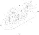
- Fig.1 is a three-dimensional structure view of a preferred embodiment of the present invention.
- the apparatus of the preferred embodiment mainly comprises a base 1, a detecting assembly provided on a first half portion 103 of the base 1, and a braking assembly provided on a second half portion 104 of the base 1.
- the terms for representing direction such as the first half portion 103, the second half portion 104, the front view side 101 and the rear view side 102 of the base 1 as described below, and the like are used in order to be convenient to describe, and that the terms should not be understood as any limit for shape, structure and position of the base 1 and for shape, structure and position of the detecting assembly and the braking assembly provided on the base 1.
- the base 1 mainly is used to support the detecting assembly and the braking assembly.
- the base 1 is plate-shaped, and a pull-tab 105 mainly used to connect a fixture is fixed to a front end of the base 1.
- the detecting assembly for detecting the movement direction of a winch traction rope is provided on the first half portion 103 of the base 1; the detecting assembly perceives the change of the direction and transmits the change to the braking assembly when the traction rope moves in the opposition direction (namely when the traction rope is far away from the winch).
- the braking assembly is provided on the second half portion 104 of the base 1 and connects the detecting assembly; the detecting assembly triggers the braking assembly when the movement of the winch traction rope (sometimes named as the winching mill traction rope) in an opposite direction is detected by the detecting assembly, so as to make the braking assembly clamp the winch traction rope.
- the winch traction rope sometimes named as the winching mill traction rope
- the detecting assembly mainly comprises a pulley mechanism for detecting the movement direction of the winch traction rope and a transmission mechanism for transmitting the signal of the movement direction change of the traction rope to the braking assembly.
- the pulley mechanism is coupled to the transmission mechanism.
- the pulley mechanism comprises: three pulleys respectively being a first pulley 24, a second pulley 34 and an unlabeled third pulley having the same structure with the first pulley 24, and corresponding support housings.
- the grooves of the three pulleys are used to limit the winch traction rope, wherein the second pulley 34 is used to detect the change of the movement direction of the traction rope and transmits the change to the transmission mechanism by a rotary shaft 36 thereof, so that the transmission mechanism triggers the braking assembly when the change of the movement direction of the winch traction rope is detected by the second pulley 34, thereby clamping the traction rope to prevent the retreat phenomenon from generating.
- the axes of the first pulley 24, the second pulley 34 and the third pulley in the pulley mechanism are parallel, the first pulley 24 is provided on one side of the second pulley 34 and the third pulley is provided on the other side of the second pulley 34.
- the height of the second pulley is different from those of the first pulley 24 and the third pulley 34, for example, the heights of the first pulley 24 and the third pulley are lower than that of the second pulley 34, so that the traction rope passes the upper groove of the first pulley 24, the lower groove of the second pulley 34 and the upper groove of the third pulley, that is to say, the traction rope passes the grooves of the three pulleys in the state of slight bend, so as to be capable to closely embed the winch traction rope into the grooves of the first pulley 24, the second pulley 34 and the third pulley, thereby more closely contacting the traction rope with the second pulley 34, this can make the second pulley 34 perceive the change of the direction of the traction rope more timely and accurately.
- the first pulley 24 is provided between two ear plates 21 and 22, the ear plate 22 on the front view side 101 of the base 1 has an integral structure, the ear plate 21 on the rear view side 102 of the base 1 has a structure with two section including an upper ear plate 211 and a lower ear plate 212, a lower end of the upper ear plate 211 is hinged to the upper end of the lower ear plate 212, that is to say, the upper ear plate 211 can flip toward the rear view side 102. Since the third pulley has the same structure with the first pulley 24, the structure of the third pulley is not repeated herein.
- the second pulley 34 is provided between two ear plates 31 and 35, a gap 30 capable to pass the traction rope is below the ear plate 31, and a vertical plate 32 is below the gap 30.
- the upper ear plate 211 is flipped toward the rear view side 102, so as to embed the traction rope into the grooves of the three pulleys through the upper ear plate 211 and the gap 30. This shows that the turnover design for the upper ear plate 211 and the suspending design for the ear plate 31 are easy to embed the traction rope into the grooves of the three pulleys in site.
- the preferred embodiment also includes a reinforcing plate in order to enhance strength of the ear plates for supporting the three pulleys and avoid the disengagement of the traction rope, the reinforcing plate is tightly fixed on the ear plate 31 and the vertical plate 32 by bolts and meanwhile also is extended and covered on the upper ear plate 211 and the lower ear plate 212 after embedding the traction rope into the grooves of the pulleys.
- both the first pulley 24 and the third pulley of the preferred embodiment include a height-adjusting mechanism for adjusting heights of the first pulley 23 and the third pulley, thereby more closely contacting the winch traction rope with the second pulley.
- a vertical stud bolt 82 and a driving plate without illustration are provided below the base 1, a thread block 81 on which a thread hole is provided is provided on the base 1, the top end of the stud bolt 82 passes through the base 1 and is screwed into the thread hole and meanwhile the driving plate connects the stud bolt 82 by thread.
- the two ends of the rotary shaft 23 of the first pulley 24 can movably up and down pass through the ear plates 21 and 22 and then respectively are provided at the top end of a stand column 25, the lower end of the stand column 25 passes through the base 1 and is fixed on the driving plate.
- the stud bolt 82 drives the driving plate to move up and down, and the driving plate drives the stand column 25 to slide up and down, thereby driving the rotary shaft 23 and the first pulley 24 to move up and down.
- the height adjustment of the first pulley 24 is easy to embed the traction rope into the groove thereof, and meanwhile is easy to adjust frictional force between the traction rope and the three pulleys.
- the transmission mechanism comprises an outer wheel 37, a ratchet-pawl mechanism 38 and a link mechanism.
- the ratchet-pawl mechanism 38 is provided at one end of the rotary shaft 36 of the second pulley 34 passing through the ear plate 35, and a vertical plate 39 is supported at the end of the rotary shaft 36.
- the pawl of the ratchet-pawl mechanism 38 drives the ratchet of the ratchet-pawl mechanism 38 to turn when the winch traction rope moves in the opposite direction.
- the outer wheel 37 is fixed on the outside of the ratchet of the ratchet-pawl mechanism 38.
- the outer wheel 37 and the ratchet-pawl mechanism 38 have the same structure with a bicycle free wheel (namely, overrunning clutch).
- a bicycle free wheel namely, overrunning clutch.
- the embodiment shown in Fig.1 directly employs a bicycle free wheel. The bicycle free wheel stays still during normal traction, once the traction rope moves in the opposite direction, the bicycle free wheel will be driven to turn.
- the link mechanism is connected to the outer wheel 37 and is used to transmit the rotation of the outer wheel 37 to the braking assembly, so as to trigger the braking assembly.
- the link mechanism comprises a first link 51, a second link 52, a third link 55 and a fourth link 6.
- a first end of the first link 51 is connected to the outer wheel 37.
- a first end of the second link 52 is hinged to a second end of the first link 51 and a second end thereof is hinged to a support mount 53 on the base 1.
- a middle portion of the third link 55 is hinged to a support mount 58 on the base 1 through a hinging plate 59, a horizontal plate 54 which is provided below the first end of the second link 52 is provided to extend toward the lower side of the outer wheel 37 from a first end of the third link 55.
- the outer wheel 37 drives the second link 52 to incline toward the first end of the third link 55 when rotating and to downward press the third link 55, so as to upward bend the second end of the third link 55, thereby triggering the braking assembly.
- a first end of the fourth link 6 is upward bent to form an L shape and a second end thereof is connected to a wire clamp device 4 of the braking assembly.
- the second end 551 of the third link 55 is downward bent to form an L shape and engages with the first end 61 of the fourth link 6.
- the second end 551 of the third link 55 disengages from the first end 61 of the fourth link 6 when the second end of the third link 55 is upward bent, thereby triggering the wire clamp device 4 of the braking assembly.
- the preferred embodiment also includes a limit frame 57 having a door-shaped structure, and the third link 55 passes through the limit frame 57.
- a vertical compression spring 56 is provided below the first end of the third link 55 and is fixed between the third link 55 and the base 1.
- the braking assembly comprises a wire clamp device 4 fixed on the base 1 and a limit pulley 73.
- the wire clamp device 4 includes a clamping groove 40 and a pulling handle 41. Since the wire clamp device 4 belongs to the art, the structure thereof only is schematically shown in Fig.1 and is not repeated herein.
- the clamping groove 40 is in the same plane with the grooves of the above-mentioned three pulleys, the front end 412 of the pulling handle 41 connects the second end of the fourth link 6, and the rear end 411 thereof is a pulling handle ring.
- the groove of the limit pulley 73 as a limit groove of the traction rope corresponds to the clamping groove 40 and is used to limit the winch traction rope, thereby preventing the traction rope from swinging.
- the rotary shaft 74 of the limit pulley 73 is provided on ear plates 71 and 72, the ear plate 71 reversibly is hinged on the base 1 relative to the ear plate 72, the second ear plate 72 is fixed on the base 1, namely similar to a support housing of the first pulley 24; the ear plate 71 includes an upper ear plate 711 and a lower ear plate 712, the upper ear plate 711 is capable to flip toward the rear view side 102 of the base 1, so as to be easy to embed the traction rope into the clamping groove 40 and the groove of the limit pulley 73.
- the upper end of the ear plate 72 is a bolt 75 and two nuts 76, the end portion of the rotary shaft 74 is located on the lower side of the bolt 75.
- the bolt 75 is rotated when flipping the upper ear plate 711, which is easy to disengage the rotary shaft 74 from the ear plate 72.
- the upper ear plate 711 is erected after the traction rope is placed into the clamping groove 40 and between the ear plate 71 and the ear plate 72, the traction rope is embedded into the groove of the limit pulley 73, and then the bolt 75 is screwed into the two nuts 76, so as to make the bolt 75 tightly press on the rotary shaft 74.
- the pulling handle ring of the wire clamp device 4 can connect a tractor installed with the winch, the pulling handle ring 105 connects a fixture like a ground anchor through a hawser and the like. Normal operation can be preformed after the traction rope is embedded into the grooves of the first pulley 24, the second pulley 34, the third pulley and the limit pulley, and the clamping groove 40 according to the abovementioned description.
- the present invention can prevent the retreat phenomenon from generating in the simple and easy means, thereby greatly improve safety of power operation site. And meanwhile the present invention is simple in structure, low in cost and easy to widely be spread. Certainly, the present invention not only applies to the winch traction rope, but also any situation in which the movement of the rope in single direction is required and meanwhile the movement of the rope in the opposite direction is avoided. All of changes in the range of the present invention or in the range equal to the present invention are contained by the present invention.
Landscapes
- Electric Cable Installation (AREA)
- Maintenance And Inspection Apparatuses For Elevators (AREA)
- Emergency Lowering Means (AREA)
Claims (8)
- Vorrichtung zur Rücklaufverhinderung, mit:einer Basis (1) zum Bereitstellen eine Halterung;einer an der Basis (1) vorgesehenen Erfassungsanordnung zum Erfassen der Bewegungsrichtung eines Windenzugseils; undeiner Bremsanordnung, die an der Basis (1) vorgesehen und mit der Erfassungsanordnung verbunden ist; wobei die Erfassungsanordnung die Bremsanordnung auslöst, wenn durch die Erfassungsanordnung die Bewegung des Windenzugseils in eine Gegenrichtung erfasst wird, um die Bremsanordnung zu veranlassen, das Windenzugseil festzuklemmen;dadurch gekennzeichnet, dass die Erfassungsanordnung aufweist:einen Seilscheibenmechanismus, der mindestens eine Seilscheibe, von der eine Rille verwendet wird, um das Windenzugseil zu begrenzen, um die Bewegungsrichtung des Windenzugseils zu erfassen, und einen Getriebemechanismus aufweist, der mit einer Drehwelle der Seilscheibe und der Bremsanordnung zum Auslösen der Bremsanordnung zur Zeit der durch den Seilscheibenmechanismus erfassten Änderung der Bewegungsrichtung des Windenzugseils verbunden ist, wobei der Seilscheibenmechanismus eine erste Seilscheibe (24), eine zweite Seilscheibe (34) und eine dritte Seilscheibe aufweist, deren Achsen parallel sind, die erste Seilscheibe (24) und die dritte Seilscheibe auf beiden Seiten der zweiten Seilscheibe (34) vorgesehen sind, und sich die Höhe der zweiten Seilscheibe (34) von der der ersten Seilscheibe (24) und der dritten Seilscheibe unterscheidet, so dass das Windenzugseil eng in die Rillen der ersten Seilscheibe (24), der zweiten Seilscheibe (34) und der dritten Seilscheibe eingebettet ist, und die Drehwelle (36) der zweiten Seilscheibe (34) mit dem Getriebemechanismus verbunden ist.
- Vorrichtung zur Rücklaufverhinderung nach Anspruch 1, wobei die Basis (1) plattenförmig ist und ein Zugring (105) an einem vorderen Ende der Basis (1) befestigt ist.
- Vorrichtung zur Rücklaufverhinderung nach Anspruch 1, wobei der Getriebemechanismus aufweist:einen Sperrklinkenmechanismus (38), der an einem Ende der Drehwelle (36) der Seilscheibe (34) vorgesehen ist, von dem die Sperrklinke verwendet wird, um das Klinkenrad des Sperrklinkenmechanismus anzutreiben, um sich zur Zeit der Bewegung eines Windenzugseils in die Gegenrichtung zu drehen;ein äußeres Rad (37), das an der Außenseite des Klinkenrads des Sperrklinkenmechanismus (38) befestigt ist; undeinen Verbindungsmechanismus, der mit dem äußeren Rad (37) zum Übertragen der Drehung des äußeren Rads (37) auf die Bremsanordnung verbunden ist, um die Bremsanordnung auszulösen.
- Vorrichtung zur Rücklaufverhinderung nach Anspruch 3, wobei der Verbindungsmechanismus aufweist:ein erstes Verbindungselement (51), von dem ein erstes Ende mit dem äußeren Rad (37) verbunden ist;ein zweites Verbindungselement (52), von dem ein erstes Ende mit einem zweiten Ende des ersten Verbindungselements (51) gelenkig verbunden ist und von dem ein zweites Ende mit der Basis (1) gelenkig verbunden ist; undein drittes Verbindungselement (55), von dem ein Mittelabschnitt mit der Basis (1) gelenkig verbunden ist und von dem ein erstes Ende unter dem ersten Ende des zweiten Verbindungselements (52) vorgesehen ist, wobei das äußere Rad (37) das zweite Verbindungselement (52) antreibt, sich zum ersten Ende des dritten Verbindungselements (55) zu neigen, wenn es sich dreht, und um das dritte Verbindungselement (55) nach unten zu drücken, um das zweite Ende (551) des dritten Verbindungselement (55) nach oben zu biegen, wodurch die Bremsanordnung ausgelöst wird.
- Vorrichtung zur Rücklaufverhinderung nach Anspruch 4, wobei der Verbindungsmechanismus ferner aufweist:ein viertes Verbindungselement (6), von dem ein erstes Ende nach oben gebogen ist, so dass es eine L-Form bildet und von dem ein zweites Ende mit der Bremsanordnung verbunden ist;das zweite Ende (551) des dritten Verbindungselements (55) nach unten gebogen ist, so dass es eine L-Form bildet und mit dem ersten Ende des vierten Verbindungselements (6) in Eingriff tritt; wobei sich das zweite Ende (551) des dritten Verbindungselements (55) vom ersten Ende des vierten Verbindungselements (6) löst, wenn das zweite Ende (551) des dritten Verbindungselements (55) nach oben gebogen wird, wodurch die Bremsanordnung ausgelöst wird.
- Vorrichtung zur Rücklaufverhinderung nach Anspruch 5, wobei die Bremsanordnung aufweist:eine Seilklemmvorrichtung (4), die an der Basis (1) befestigt ist, die eine Klemmrille (40), die sich in derselben Ebene mit der Rille der Seilscheibe befindet, und einen Zuggriff (41) aufweist, der mit dem zweiten Ende des vierten Verbindungselements (6) verbunden ist; undeine Begrenzungsrille, die der Klemmrille (40) entspricht, zum Begrenzen des Windenzugseils.
- Vorrichtung zur Rücklaufverhinderung nach Anspruch 6, wobei die Begrenzungsrille eine Rille einer Begrenzungsseilscheibe (73) ist, die Drehwelle (74) der Begrenzungsseilscheibe (73) an einer erste Ösenplatte (71) und einer zweite Ösenplatte (72) vorgesehen ist, wobei die erste Ösenplatte (71) relativ zur zweiten Ösenplatte (72) reversibel an der Basis (1) angelenkt ist und die zweite Ösenplatte (72) an der Basis (1) befestigt ist.
- Vorrichtung zur Rücklaufverhinderung nach Anspruch 1, wobei sowohl die erste Seilscheibe (24) als auch die dritte Seilscheibe einen Höheneinstellmechanismus zum Einstellen der Höhe der ersten Seilscheibe (24) und der dritten Seilscheibe aufweist, wodurch das Windenzugseil in engeren Kontakt mit der zweiten Seilscheibe (34) gebracht wird.
Applications Claiming Priority (3)
| Application Number | Priority Date | Filing Date | Title |
|---|---|---|---|
| CN201410057446.8A CN103956676B (zh) | 2014-02-20 | 2014-02-20 | 防跑磨装置 |
| CN201420072865.4U CN203722132U (zh) | 2014-02-20 | 2014-02-20 | 防跑磨装置 |
| PCT/CN2014/078384 WO2015123929A1 (zh) | 2014-02-20 | 2014-05-26 | 防跑磨装置 |
Publications (3)
| Publication Number | Publication Date |
|---|---|
| EP3109959A1 EP3109959A1 (de) | 2016-12-28 |
| EP3109959A4 EP3109959A4 (de) | 2017-09-27 |
| EP3109959B1 true EP3109959B1 (de) | 2019-02-27 |
Family
ID=53877582
Family Applications (1)
| Application Number | Title | Priority Date | Filing Date |
|---|---|---|---|
| EP14883308.0A Not-in-force EP3109959B1 (de) | 2014-02-20 | 2014-05-26 | Vorrichtung zur verhinderung von gegenläufigem rückgang |
Country Status (3)
| Country | Link |
|---|---|
| EP (1) | EP3109959B1 (de) |
| JP (1) | JP6063089B2 (de) |
| WO (1) | WO2015123929A1 (de) |
Families Citing this family (2)
| Publication number | Priority date | Publication date | Assignee | Title |
|---|---|---|---|---|
| CN111302249B (zh) * | 2020-02-19 | 2024-11-26 | 山西灵石华瀛天星柏沟煤业有限公司 | 一种不间断连接的绞车牵引用连接装置 |
| CN114572254B (zh) * | 2022-02-12 | 2025-02-14 | 宁波华翔东方电力机具有限公司 | 一种可中途返回的自走车 |
Family Cites Families (11)
| Publication number | Priority date | Publication date | Assignee | Title |
|---|---|---|---|---|
| US5388781A (en) * | 1991-01-30 | 1995-02-14 | Sauber; Charles J. | Cable pulling and reeling apparatus having anti-spill device and method |
| JP2587911B2 (ja) * | 1994-10-05 | 1997-03-05 | 東光電気工事株式会社 | 架線ウインチワイヤクランプ規整装置 |
| JP2763514B2 (ja) * | 1996-02-23 | 1998-06-11 | 東亜発動機株式会社 | 送電線架設安全装置 |
| JP3085526B2 (ja) * | 1997-11-04 | 2000-09-11 | 日本電気株式会社 | 記憶装置 |
| ITUD20010024A1 (it) * | 2001-02-09 | 2002-08-09 | Tesmec Spa | Dispositivo di rilevamento della tensione per macchine di tesatura e macchina di tesatura adottante tale dispositivo |
| JP2007288837A (ja) * | 2006-04-12 | 2007-11-01 | Chugoku Electric Power Co Inc:The | 電線引き寄せ具及び電線引き寄せ方法 |
| US8505878B2 (en) * | 2007-04-05 | 2013-08-13 | Lionel O. Barthold | Apparatus and method for enhancing the reconductoring of overhead electric power lines |
| JP2010220453A (ja) * | 2009-03-19 | 2010-09-30 | Tokyo Electric Power Co Inc:The | 吊線(メッセンジャー)架設用のバックテンション装置と、このバックテンション装置を用いた吊線(メッセンジャー)の架設工法 |
| CN202004379U (zh) * | 2011-03-22 | 2011-10-05 | 辽宁省电力有限公司丹东供电公司 | 导线动力牵引机 |
| CN202084851U (zh) * | 2011-06-28 | 2011-12-21 | 湖州电力局 | 防跑线卡线器 |
| CN102709849B (zh) * | 2012-06-25 | 2017-03-29 | 国家电网公司 | 手动多功能紧线装置及一种导线紧线方法 |
-
2014
- 2014-05-26 JP JP2016503534A patent/JP6063089B2/ja not_active Expired - Fee Related
- 2014-05-26 EP EP14883308.0A patent/EP3109959B1/de not_active Not-in-force
- 2014-05-26 WO PCT/CN2014/078384 patent/WO2015123929A1/zh not_active Ceased
Non-Patent Citations (1)
| Title |
|---|
| None * |
Also Published As
| Publication number | Publication date |
|---|---|
| JP6063089B2 (ja) | 2017-01-18 |
| JP2016519029A (ja) | 2016-06-30 |
| EP3109959A1 (de) | 2016-12-28 |
| EP3109959A4 (de) | 2017-09-27 |
| WO2015123929A1 (zh) | 2015-08-27 |
Similar Documents
| Publication | Publication Date | Title |
|---|---|---|
| KR102311377B1 (ko) | 철탑의 휴대용 전동윈치 장치 | |
| CN215626409U (zh) | 一种船舶自动排缆绞车 | |
| CN109132904A (zh) | 绞车装置和无人船 | |
| CN203770987U (zh) | 基于升降式高杆灯的闭路摄像的自动升降装置 | |
| CN103112791B (zh) | 一种钢丝绳辅助缠绕装置 | |
| CN116374842A (zh) | 一种基于智能化传感的工程用管道起重机及其方法 | |
| CN202076729U (zh) | 带制动装置的牵引绳放线架 | |
| EP3109959A1 (de) | Vorrichtung zur verhinderung von gegenläufigem rückgang | |
| CN213445941U (zh) | 一种悬吊架安全保护装置 | |
| CN116119560B (zh) | 一种卷筒装置 | |
| CN117855992A (zh) | 挂拆接地线智能设备和挂线方法 | |
| CN218472618U (zh) | 一种架空地线链索混式短距离通用提升装置 | |
| CN205170251U (zh) | 一种松绳保护监测报警装置 | |
| CN103956676B (zh) | 防跑磨装置 | |
| CN116081463A (zh) | 一种双滚筒装置的工作方法 | |
| CN203734217U (zh) | 一种架空线路直线改耐张带电紧线器 | |
| CN111689417B (zh) | 一种建筑用防坠落提升机 | |
| CN105762697B (zh) | 输电线路施工中的防跑磨装置 | |
| CN210475116U (zh) | 热水器水箱自动绕管机 | |
| CN203722132U (zh) | 防跑磨装置 | |
| CN203582361U (zh) | 一种拖缆绞车 | |
| CN203255906U (zh) | 起重机卷筒压绳装置 | |
| CN111889998A (zh) | 一种led路灯的固定安装装置 | |
| KR101871051B1 (ko) | 중심축 이동형 활차 및 이를 이용한 전선장력 모니터링 시스템 | |
| CN212229077U (zh) | 一种电动葫芦快速测试台 |
Legal Events
| Date | Code | Title | Description |
|---|---|---|---|
| PUAI | Public reference made under article 153(3) epc to a published international application that has entered the european phase |
Free format text: ORIGINAL CODE: 0009012 |
|
| STAA | Information on the status of an ep patent application or granted ep patent |
Free format text: STATUS: REQUEST FOR EXAMINATION WAS MADE |
|
| 17P | Request for examination filed |
Effective date: 20160916 |
|
| AK | Designated contracting states |
Kind code of ref document: A1 Designated state(s): AL AT BE BG CH CY CZ DE DK EE ES FI FR GB GR HR HU IE IS IT LI LT LU LV MC MK MT NL NO PL PT RO RS SE SI SK SM TR |
|
| AX | Request for extension of the european patent |
Extension state: BA ME |
|
| DAX | Request for extension of the european patent (deleted) | ||
| A4 | Supplementary search report drawn up and despatched |
Effective date: 20170828 |
|
| RIC1 | Information provided on ipc code assigned before grant |
Ipc: H02G 1/04 20060101ALI20170822BHEP Ipc: H02G 1/02 20060101AFI20170822BHEP |
|
| RIC1 | Information provided on ipc code assigned before grant |
Ipc: H02G 1/04 20060101ALI20180727BHEP Ipc: H02G 1/02 20060101AFI20180727BHEP |
|
| GRAP | Despatch of communication of intention to grant a patent |
Free format text: ORIGINAL CODE: EPIDOSNIGR1 |
|
| STAA | Information on the status of an ep patent application or granted ep patent |
Free format text: STATUS: GRANT OF PATENT IS INTENDED |
|
| INTG | Intention to grant announced |
Effective date: 20181001 |
|
| RIN1 | Information on inventor provided before grant (corrected) |
Inventor name: YIN, ZHIRUI |
|
| GRAS | Grant fee paid |
Free format text: ORIGINAL CODE: EPIDOSNIGR3 |
|
| GRAA | (expected) grant |
Free format text: ORIGINAL CODE: 0009210 |
|
| STAA | Information on the status of an ep patent application or granted ep patent |
Free format text: STATUS: THE PATENT HAS BEEN GRANTED |
|
| AK | Designated contracting states |
Kind code of ref document: B1 Designated state(s): AL AT BE BG CH CY CZ DE DK EE ES FI FR GB GR HR HU IE IS IT LI LT LU LV MC MK MT NL NO PL PT RO RS SE SI SK SM TR |
|
| REG | Reference to a national code |
Ref country code: GB Ref legal event code: FG4D |
|
| RIN1 | Information on inventor provided before grant (corrected) |
Inventor name: AN, SHIHUA Inventor name: GAO, BING Inventor name: WANG, ZHENGPING Inventor name: LIU, WEI Inventor name: WU, XIAOGUANG Inventor name: YIN, ZHIRUI Inventor name: WANG, YINZHONG |
|
| REG | Reference to a national code |
Ref country code: CH Ref legal event code: EP |
|
| REG | Reference to a national code |
Ref country code: AT Ref legal event code: REF Ref document number: 1102708 Country of ref document: AT Kind code of ref document: T Effective date: 20190315 |
|
| REG | Reference to a national code |
Ref country code: IE Ref legal event code: FG4D |
|
| REG | Reference to a national code |
Ref country code: DE Ref legal event code: R096 Ref document number: 602014042120 Country of ref document: DE |
|
| REG | Reference to a national code |
Ref country code: NL Ref legal event code: MP Effective date: 20190227 |
|
| REG | Reference to a national code |
Ref country code: LT Ref legal event code: MG4D |
|
| PG25 | Lapsed in a contracting state [announced via postgrant information from national office to epo] |
Ref country code: LT Free format text: LAPSE BECAUSE OF FAILURE TO SUBMIT A TRANSLATION OF THE DESCRIPTION OR TO PAY THE FEE WITHIN THE PRESCRIBED TIME-LIMIT Effective date: 20190227 Ref country code: NL Free format text: LAPSE BECAUSE OF FAILURE TO SUBMIT A TRANSLATION OF THE DESCRIPTION OR TO PAY THE FEE WITHIN THE PRESCRIBED TIME-LIMIT Effective date: 20190227 Ref country code: NO Free format text: LAPSE BECAUSE OF FAILURE TO SUBMIT A TRANSLATION OF THE DESCRIPTION OR TO PAY THE FEE WITHIN THE PRESCRIBED TIME-LIMIT Effective date: 20190527 Ref country code: SE Free format text: LAPSE BECAUSE OF FAILURE TO SUBMIT A TRANSLATION OF THE DESCRIPTION OR TO PAY THE FEE WITHIN THE PRESCRIBED TIME-LIMIT Effective date: 20190227 Ref country code: FI Free format text: LAPSE BECAUSE OF FAILURE TO SUBMIT A TRANSLATION OF THE DESCRIPTION OR TO PAY THE FEE WITHIN THE PRESCRIBED TIME-LIMIT Effective date: 20190227 Ref country code: PT Free format text: LAPSE BECAUSE OF FAILURE TO SUBMIT A TRANSLATION OF THE DESCRIPTION OR TO PAY THE FEE WITHIN THE PRESCRIBED TIME-LIMIT Effective date: 20190627 |
|
| PG25 | Lapsed in a contracting state [announced via postgrant information from national office to epo] |
Ref country code: IS Free format text: LAPSE BECAUSE OF FAILURE TO SUBMIT A TRANSLATION OF THE DESCRIPTION OR TO PAY THE FEE WITHIN THE PRESCRIBED TIME-LIMIT Effective date: 20190627 Ref country code: LV Free format text: LAPSE BECAUSE OF FAILURE TO SUBMIT A TRANSLATION OF THE DESCRIPTION OR TO PAY THE FEE WITHIN THE PRESCRIBED TIME-LIMIT Effective date: 20190227 Ref country code: HR Free format text: LAPSE BECAUSE OF FAILURE TO SUBMIT A TRANSLATION OF THE DESCRIPTION OR TO PAY THE FEE WITHIN THE PRESCRIBED TIME-LIMIT Effective date: 20190227 Ref country code: GR Free format text: LAPSE BECAUSE OF FAILURE TO SUBMIT A TRANSLATION OF THE DESCRIPTION OR TO PAY THE FEE WITHIN THE PRESCRIBED TIME-LIMIT Effective date: 20190528 Ref country code: BG Free format text: LAPSE BECAUSE OF FAILURE TO SUBMIT A TRANSLATION OF THE DESCRIPTION OR TO PAY THE FEE WITHIN THE PRESCRIBED TIME-LIMIT Effective date: 20190527 Ref country code: RS Free format text: LAPSE BECAUSE OF FAILURE TO SUBMIT A TRANSLATION OF THE DESCRIPTION OR TO PAY THE FEE WITHIN THE PRESCRIBED TIME-LIMIT Effective date: 20190227 |
|
| REG | Reference to a national code |
Ref country code: AT Ref legal event code: MK05 Ref document number: 1102708 Country of ref document: AT Kind code of ref document: T Effective date: 20190227 |
|
| PG25 | Lapsed in a contracting state [announced via postgrant information from national office to epo] |
Ref country code: ES Free format text: LAPSE BECAUSE OF FAILURE TO SUBMIT A TRANSLATION OF THE DESCRIPTION OR TO PAY THE FEE WITHIN THE PRESCRIBED TIME-LIMIT Effective date: 20190227 Ref country code: RO Free format text: LAPSE BECAUSE OF FAILURE TO SUBMIT A TRANSLATION OF THE DESCRIPTION OR TO PAY THE FEE WITHIN THE PRESCRIBED TIME-LIMIT Effective date: 20190227 Ref country code: CZ Free format text: LAPSE BECAUSE OF FAILURE TO SUBMIT A TRANSLATION OF THE DESCRIPTION OR TO PAY THE FEE WITHIN THE PRESCRIBED TIME-LIMIT Effective date: 20190227 Ref country code: EE Free format text: LAPSE BECAUSE OF FAILURE TO SUBMIT A TRANSLATION OF THE DESCRIPTION OR TO PAY THE FEE WITHIN THE PRESCRIBED TIME-LIMIT Effective date: 20190227 Ref country code: IT Free format text: LAPSE BECAUSE OF FAILURE TO SUBMIT A TRANSLATION OF THE DESCRIPTION OR TO PAY THE FEE WITHIN THE PRESCRIBED TIME-LIMIT Effective date: 20190227 Ref country code: DK Free format text: LAPSE BECAUSE OF FAILURE TO SUBMIT A TRANSLATION OF THE DESCRIPTION OR TO PAY THE FEE WITHIN THE PRESCRIBED TIME-LIMIT Effective date: 20190227 Ref country code: SK Free format text: LAPSE BECAUSE OF FAILURE TO SUBMIT A TRANSLATION OF THE DESCRIPTION OR TO PAY THE FEE WITHIN THE PRESCRIBED TIME-LIMIT Effective date: 20190227 Ref country code: AL Free format text: LAPSE BECAUSE OF FAILURE TO SUBMIT A TRANSLATION OF THE DESCRIPTION OR TO PAY THE FEE WITHIN THE PRESCRIBED TIME-LIMIT Effective date: 20190227 |
|
| REG | Reference to a national code |
Ref country code: DE Ref legal event code: R097 Ref document number: 602014042120 Country of ref document: DE |
|
| PG25 | Lapsed in a contracting state [announced via postgrant information from national office to epo] |
Ref country code: PL Free format text: LAPSE BECAUSE OF FAILURE TO SUBMIT A TRANSLATION OF THE DESCRIPTION OR TO PAY THE FEE WITHIN THE PRESCRIBED TIME-LIMIT Effective date: 20190227 Ref country code: SM Free format text: LAPSE BECAUSE OF FAILURE TO SUBMIT A TRANSLATION OF THE DESCRIPTION OR TO PAY THE FEE WITHIN THE PRESCRIBED TIME-LIMIT Effective date: 20190227 |
|
| REG | Reference to a national code |
Ref country code: CH Ref legal event code: PL |
|
| PG25 | Lapsed in a contracting state [announced via postgrant information from national office to epo] |
Ref country code: AT Free format text: LAPSE BECAUSE OF FAILURE TO SUBMIT A TRANSLATION OF THE DESCRIPTION OR TO PAY THE FEE WITHIN THE PRESCRIBED TIME-LIMIT Effective date: 20190227 |
|
| PLBE | No opposition filed within time limit |
Free format text: ORIGINAL CODE: 0009261 |
|
| STAA | Information on the status of an ep patent application or granted ep patent |
Free format text: STATUS: NO OPPOSITION FILED WITHIN TIME LIMIT |
|
| PG25 | Lapsed in a contracting state [announced via postgrant information from national office to epo] |
Ref country code: CH Free format text: LAPSE BECAUSE OF NON-PAYMENT OF DUE FEES Effective date: 20190531 Ref country code: MC Free format text: LAPSE BECAUSE OF FAILURE TO SUBMIT A TRANSLATION OF THE DESCRIPTION OR TO PAY THE FEE WITHIN THE PRESCRIBED TIME-LIMIT Effective date: 20190227 Ref country code: LI Free format text: LAPSE BECAUSE OF NON-PAYMENT OF DUE FEES Effective date: 20190531 |
|
| 26N | No opposition filed |
Effective date: 20191128 |
|
| REG | Reference to a national code |
Ref country code: BE Ref legal event code: MM Effective date: 20190531 |
|
| PG25 | Lapsed in a contracting state [announced via postgrant information from national office to epo] |
Ref country code: LU Free format text: LAPSE BECAUSE OF NON-PAYMENT OF DUE FEES Effective date: 20190526 Ref country code: SI Free format text: LAPSE BECAUSE OF FAILURE TO SUBMIT A TRANSLATION OF THE DESCRIPTION OR TO PAY THE FEE WITHIN THE PRESCRIBED TIME-LIMIT Effective date: 20190227 |
|
| PG25 | Lapsed in a contracting state [announced via postgrant information from national office to epo] |
Ref country code: TR Free format text: LAPSE BECAUSE OF FAILURE TO SUBMIT A TRANSLATION OF THE DESCRIPTION OR TO PAY THE FEE WITHIN THE PRESCRIBED TIME-LIMIT Effective date: 20190227 |
|
| PG25 | Lapsed in a contracting state [announced via postgrant information from national office to epo] |
Ref country code: IE Free format text: LAPSE BECAUSE OF NON-PAYMENT OF DUE FEES Effective date: 20190526 |
|
| PG25 | Lapsed in a contracting state [announced via postgrant information from national office to epo] |
Ref country code: BE Free format text: LAPSE BECAUSE OF NON-PAYMENT OF DUE FEES Effective date: 20190531 |
|
| PG25 | Lapsed in a contracting state [announced via postgrant information from national office to epo] |
Ref country code: CY Free format text: LAPSE BECAUSE OF FAILURE TO SUBMIT A TRANSLATION OF THE DESCRIPTION OR TO PAY THE FEE WITHIN THE PRESCRIBED TIME-LIMIT Effective date: 20190227 |
|
| PG25 | Lapsed in a contracting state [announced via postgrant information from national office to epo] |
Ref country code: HU Free format text: LAPSE BECAUSE OF FAILURE TO SUBMIT A TRANSLATION OF THE DESCRIPTION OR TO PAY THE FEE WITHIN THE PRESCRIBED TIME-LIMIT; INVALID AB INITIO Effective date: 20140526 Ref country code: MT Free format text: LAPSE BECAUSE OF FAILURE TO SUBMIT A TRANSLATION OF THE DESCRIPTION OR TO PAY THE FEE WITHIN THE PRESCRIBED TIME-LIMIT Effective date: 20190227 |
|
| PGFP | Annual fee paid to national office [announced via postgrant information from national office to epo] |
Ref country code: GB Payment date: 20220325 Year of fee payment: 9 |
|
| PGFP | Annual fee paid to national office [announced via postgrant information from national office to epo] |
Ref country code: FR Payment date: 20220325 Year of fee payment: 9 |
|
| PG25 | Lapsed in a contracting state [announced via postgrant information from national office to epo] |
Ref country code: MK Free format text: LAPSE BECAUSE OF FAILURE TO SUBMIT A TRANSLATION OF THE DESCRIPTION OR TO PAY THE FEE WITHIN THE PRESCRIBED TIME-LIMIT Effective date: 20190227 |
|
| PGFP | Annual fee paid to national office [announced via postgrant information from national office to epo] |
Ref country code: DE Payment date: 20220425 Year of fee payment: 9 |
|
| REG | Reference to a national code |
Ref country code: DE Ref legal event code: R119 Ref document number: 602014042120 Country of ref document: DE |
|
| GBPC | Gb: european patent ceased through non-payment of renewal fee |
Effective date: 20230526 |
|
| PG25 | Lapsed in a contracting state [announced via postgrant information from national office to epo] |
Ref country code: DE Free format text: LAPSE BECAUSE OF NON-PAYMENT OF DUE FEES Effective date: 20231201 Ref country code: GB Free format text: LAPSE BECAUSE OF NON-PAYMENT OF DUE FEES Effective date: 20230526 |
|
| PG25 | Lapsed in a contracting state [announced via postgrant information from national office to epo] |
Ref country code: FR Free format text: LAPSE BECAUSE OF NON-PAYMENT OF DUE FEES Effective date: 20230531 |