EP3106635A1 - Schottwandkonstruktion mit integrierter flüssigkeitsförderfunktion - Google Patents
Schottwandkonstruktion mit integrierter flüssigkeitsförderfunktion Download PDFInfo
- Publication number
- EP3106635A1 EP3106635A1 EP16001155.7A EP16001155A EP3106635A1 EP 3106635 A1 EP3106635 A1 EP 3106635A1 EP 16001155 A EP16001155 A EP 16001155A EP 3106635 A1 EP3106635 A1 EP 3106635A1
- Authority
- EP
- European Patent Office
- Prior art keywords
- liquid
- bulkhead
- connecting rod
- crankshaft
- formation
- Prior art date
- Legal status (The legal status is an assumption and is not a legal conclusion. Google has not performed a legal analysis and makes no representation as to the accuracy of the status listed.)
- Granted
Links
Images



Classifications
-
- F—MECHANICAL ENGINEERING; LIGHTING; HEATING; WEAPONS; BLASTING
- F01—MACHINES OR ENGINES IN GENERAL; ENGINE PLANTS IN GENERAL; STEAM ENGINES
- F01M—LUBRICATING OF MACHINES OR ENGINES IN GENERAL; LUBRICATING INTERNAL COMBUSTION ENGINES; CRANKCASE VENTILATING
- F01M1/00—Pressure lubrication
- F01M1/06—Lubricating systems characterised by the provision therein of crankshafts or connecting rods with lubricant passageways, e.g. bores
-
- F—MECHANICAL ENGINEERING; LIGHTING; HEATING; WEAPONS; BLASTING
- F01—MACHINES OR ENGINES IN GENERAL; ENGINE PLANTS IN GENERAL; STEAM ENGINES
- F01M—LUBRICATING OF MACHINES OR ENGINES IN GENERAL; LUBRICATING INTERNAL COMBUSTION ENGINES; CRANKCASE VENTILATING
- F01M11/00—Component parts, details or accessories, not provided for in, or of interest apart from, groups F01M1/00 - F01M9/00
-
- F—MECHANICAL ENGINEERING; LIGHTING; HEATING; WEAPONS; BLASTING
- F01—MACHINES OR ENGINES IN GENERAL; ENGINE PLANTS IN GENERAL; STEAM ENGINES
- F01M—LUBRICATING OF MACHINES OR ENGINES IN GENERAL; LUBRICATING INTERNAL COMBUSTION ENGINES; CRANKCASE VENTILATING
- F01M11/00—Component parts, details or accessories, not provided for in, or of interest apart from, groups F01M1/00 - F01M9/00
- F01M11/0004—Oilsumps
-
- F—MECHANICAL ENGINEERING; LIGHTING; HEATING; WEAPONS; BLASTING
- F01—MACHINES OR ENGINES IN GENERAL; ENGINE PLANTS IN GENERAL; STEAM ENGINES
- F01M—LUBRICATING OF MACHINES OR ENGINES IN GENERAL; LUBRICATING INTERNAL COMBUSTION ENGINES; CRANKCASE VENTILATING
- F01M11/00—Component parts, details or accessories, not provided for in, or of interest apart from, groups F01M1/00 - F01M9/00
- F01M11/0004—Oilsumps
- F01M2011/005—Oilsumps with special anti-turbulence means, e.g. anti-foaming means or intermediate plates
Definitions
- the invention relates to a bulkhead wall construction for a liquid collecting device for a vehicle construction comprising a crankshaft and a connecting rod, preferably an internal combustion engine (for example an internal combustion engine).
- the invention also relates to an associated liquid collecting device.
- An object of the invention is to provide a possibility by means of which an improved and / or alternative liquid collecting device can be realized.
- the invention provides a bulkhead construction for a fluid containment device for a crankshaft and connecting rod comprising vehicle construction, e.g. Example, an internal combustion engine, in particular internal combustion engine (eg., Diesel engine) or another piston engine.
- vehicle construction e.g. Example, an internal combustion engine, in particular internal combustion engine (eg., Diesel engine) or another piston engine.
- the bulkhead construction comprises at least two fluid channels and at least two formations for rotating, in particular rotating crankshaft and / or connecting rod sections, whereby liquid, preferably via the fluid channels, from the formations acted upon, in particular from the formations out is promoted, z.
- one molding in each case serves for a rotating crankshaft and / or connecting rod section.
- the bulkhead construction is thus designed to provide a rotational movement, in particular the rotational movement performed in normal operation, the crankshaft and / or Uses connecting rod sections to apply liquid from the molds, preferably from recess to recess and / or towards a remplisstechniksabsaug Symposium.
- the bulkhead construction can therefore, in particular together with rotating crankshaft and / or connecting rod sections, have an integrated liquid conveying function.
- the bulkhead construction may be formed from a single bulkhead element or a plurality, preferably at least two, separate bulkhead elements.
- crankshaft and / or connecting rod sections expediently comprise lower, preferably lowest, crankshaft and / or connecting rod sections.
- At least one liquid channel expediently indirectly or directly connects a formation with another formation, preferably an adjacent formation, so that preferably a liquid delivery is made possible, in particular from formation to formation and / or towards a liquid extraction region.
- at least one liquid channel expediently connects a formation directly or indirectly to a liquid extraction region, so that preferably a liquid delivery is made possible, in particular from formation to formation and / or to the liquid extraction region.
- At least one liquid channel may expediently have a liquid inlet and a liquid outlet.
- the liquid inlet may be formed in a molding or adjacent thereto.
- the liquid outlet may be formed in another, preferably adjacent, shaping or adjacent thereto.
- At least one liquid channel can connect two preferably adjacent formations directly (entry into one formation and exit into another formation) or indirectly (entry into formation or adjacent thereto and exit into another formation or adjacent thereto).
- At least one liquid channel may connect a formation directly to a liquid extraction region (entry into formation and exit into liquid extraction region) or indirectly (entry into formation or adjacent thereto and exit into liquid extraction region or adjacent thereto).
- At least one liquid channel has a tapered passage cross-section to z. B. to achieve a pressure difference and / or a conveying effect.
- the passage cross-section preferably tapers in the liquid conveying direction.
- the formations prefferably be designed in accordance with the envelope geometry of the rotational movement of the crankshaft and / or connecting rod sections, in addition to a clearance dimension (eg at least 1 mm, at least 2 mm, at least 3 mm, at least 4 mm or at least 5 mm) to form the gap for fluid absorption between the formations and the rotating crankshaft and / or connecting rod sections.
- a clearance dimension eg at least 1 mm, at least 2 mm, at least 3 mm, at least 4 mm or at least 5 mm
- the envelope geometry of a crankshaft rotation movement is mapped.
- the image is designed with a defined distance such that the distance can form the gap.
- the formations may be designed so that liquid from the formations can be acted upon by means of the rotational movement of the crank and / or connecting rod sections into the liquid channels.
- the bulkhead construction preferably serves for arrangement under the vehicle construction and / or for arrangement under the crankshaft and the connecting rods.
- the bulkhead construction is preferably designed as a cover device for the liquid collecting device.
- the bulkhead construction can, for. B. be designed as a molded part, for. B. as a plastic molding, with integrated formations and / or integrated fluid channels. This z. B. allows the formations and fluid channels are integral integral part of the bulkhead construction.
- the liquid is preferably oil.
- the liquid from the formations is preferably squeezed or pumped into the liquid passages by the rotating crankshaft and / or connecting rod sections.
- the gap can thus be referred to in particular as a pump gap and / or the fluid channels, in particular as pump channels.
- At least one liquid channel in particular a liquid channel leading to the liquid suction region, can be designed as a pure opening, recess and / or hole, ie preferably with essentially no or very short longitudinal extent.
- a recess for a crankshaft bearing arrangement can be formed between the formations.
- the formations are formed as depressions in the bulkhead construction.
- the formations are preferably used for receiving rotating crankshaft and / or connecting rod sections and, alternatively or in addition to receiving liquid, in particular oil, from the vehicle construction.
- the invention is not limited to a bulkhead construction but also includes a fluid containment device for a vehicle construction comprising a crankshaft and connecting rod, e.g. As an internal combustion engine, in particular a diesel engine, or another piston engine.
- the fluid collection device is provided with a bulkhead construction as disclosed herein.
- the liquid suction region is preferably arranged substantially in the middle of the liquid tank.
- the center is expediently promoted because here is the diesstechniksabsaug Society, in particular with the liquid suction (Flüsstechniksabsaugkorb).
- the copesstechniksabsaug drove has constantly and thus at virtually any angle below the liquid level of copesstechniksabsaug Systemss, otherwise air would be sucked into the liquid circuit and thus z. B. engine lubrication could no longer or at least not properly be guaranteed.
- the vehicle construction preferably has a z. B. stationary internal combustion engine, in particular diesel engine includes. However, it may also include another piston engine (eg, lubrication circuit, oil pan, etc.).
- another piston engine eg, lubrication circuit, oil pan, etc.
- the bulkhead construction comprises several formations, for. B. at least four, at least five or at least six formations, wherein expedient in each case a molding for each rotating crankshaft and / or connecting rod is executed.
- the bulkhead construction 1 is designed as a cover device for the Olauffangvoruze F and arranged under the crankshaft 2 and the connecting rod 3.1 to 3.6.
- the formations A1 to A6 are formed so that by means of the rotational movement of the crankshaft and / or connecting rod oil from the formations A1 to A6 in the liquid channels K1 to K6 is acted upon, so that an oil extraction of shaping to shaping towards the ⁇ labsaug Colour 5 is achieved ,
- oil from the formation A6 is applied to the formation A5 via the liquid channel K6, oil from the formation A5 is applied via the liquid channel K5 to the formation A4, and oil is conveyed from the formation A4 via the liquid channel K4 to the oil extraction region 5.
- the bulkhead construction 1 can therefore fulfill an integrated oil production function together with the rotating crankshaft and / or connecting rod sections.
- the formations A1 to A6 are formed in particular according to the envelope geometry of the rotational movement of the crankshaft and / or connecting rod sections, in addition a distance dimension for forming the gap S. It follows that the formations A1 to A6 map the envelope geometry of a crankshaft rotation movement, plus a defined distance to Formation of the gap S.
- the oil production from the formations A1 to A6 and thus the effectiveness of integrated in the bulkhead construction 1 oil production function depends in particular on the gap the gap S (the smaller the gap S, the smaller the gap losses) and the passage cross sections of the oil passages K1 to K6.
- the oil production from the formations A1 to A6 and thus the effectiveness of the integrated in the bulkhead construction 1 oil production function is also dependent on the operating state of the vehicle device V, in particular from the engine and / or crankshaft speed of the vehicle device V.
- FIG. 2 shows another sectional view of the bulkhead construction 1 and the oil trap F of FIG. 1 , wherein for purposes of illustration not all parts are provided with reference numerals.
- FIGS. 3 and 4 show a bulkhead construction 1 according to an embodiment of the invention, as shown in FIGS FIGS. 1 and 2 is executed.
- Reference numeral 7 indicates optional recesses in the bulkhead structure 1 for the crankshaft bearing.
- the oil passages K3 and K4 are made very short and can be carried out in the context of the invention as a mere oil passage opening.
- FIG. 4 shows that an inlet of an oil passage may be formed in a formation, the associated outlet but not necessarily formed in a molding, but may also be formed adjacent thereto.
- the bulkhead structure 1 has expedient to be designed so that oil from the outlet can flow into the associated molding.
- the bulkhead construction 1 z. B. a slope section towards the associated. Have shape.
- FIG. 5 shows a sectional view of the bulkhead construction 1 and the Olauffangvoriques F in addition to the vehicle construction V of FIGS. 1 and 2 ,
- FIG. 5 again, the principle of operation of the invention will be apparent, namely, that in the bulkhead construction, a formation for receiving a rotating, lower crankshaft and / or connecting rod is formed and by the rotating crankshaft and / or connecting rod oil from the molding, in particular from the Gap between the molding and the rotating crankshaft and / or connecting rod section, is conveyed out, in particular in an oil passage, so that suitably an oil requirement is made possible to the ⁇ labsaug Symposium Silver, a formation for receiving a rotating, lower crankshaft and / or connecting rod is formed and by the rotating crankshaft and / or connecting rod oil from the molding, in particular from the Gap between the molding and the rotating crankshaft and / or connecting rod section, is conveyed out, in particular in an oil passage, so that suitably an oil requirement is made possible to the ⁇ labsaug Symposium Society.
- FIG. 6 shows a schematic perspective view of two adjacent formations A6 and A5, in particular two connecting rod violins with allowance.
- FIG. 6 First, it can be seen that the oil channels K6 and K5 serve to connect the two formations A6 and A5.
- the entrance of the oil passage K6 is formed in the formation A6, the exit of which is adjacent to the formation A5.
- the entrance of the oil passage K5 is formed in the formation A5, the exit of which may be formed in the molding A4 or adjacent thereto.
- FIG. 6 shows, moreover, that the passage cross-section of the respective oil passages K6 and K5 is designed to be tapered, specifically in the oil conveying direction, ie from the formation A6 to the formation A5. As a result, a pressure difference and / or an oil delivery effect can be achieved.
- the narrowing passage cross section expediently leads to an acceleration of the transported oil.
- the oil mass flow at the exit of an oil channel may be thrown against the adjacent formation or adjacent to it.
- FIG. 7 shows a perspective view of the bulkhead structure 1, the oil trap F and the vehicle construction V with the crankshaft 2 and the connecting rod 3.1 to 3.6.
Landscapes
- Engineering & Computer Science (AREA)
- Mechanical Engineering (AREA)
- General Engineering & Computer Science (AREA)
- Shafts, Cranks, Connecting Bars, And Related Bearings (AREA)
- Lubrication Details And Ventilation Of Internal Combustion Engines (AREA)
- Lubrication Of Internal Combustion Engines (AREA)
- Details Of Rigid Or Semi-Rigid Containers (AREA)
- General Details Of Gearings (AREA)
- Structures Of Non-Positive Displacement Pumps (AREA)
Abstract
Description
- Die Erfindung betrifft eine Schottwandkonstruktion für eine Flüssigkeitsauffangvorrichtung für eine eine Kurbelwelle und Pleuel umfassende Fahrzeugkonstruktion, vorzugsweise eine Verbrennungskraftmaschine (z. B. ein Verbrennungsmotor). Die Erfindung betrifft ebenfalls eine zugehörige Flüssigkeitsauffangvorrichtung.
- Im Stand der Technik sind Öl-Auffangvorrichtungen zur Anordnung unter Kurbelwellen-Pleuel-Konstruktionen in unterschiedlichsten Ausführungsformen bekannt. Nachteilig bei herkömmlichen Öl-Auffangvorrichtungen ist insbesondere, dass sich bei einer Schräglage Öl in Eckbereichen der Öl-Auffangvorrichtungen sammeln kann, mit der Folge, dass ein Saugkorb oberhalb des Ölspiegels des abzusaugenden Öls liegt. Ein weiterer Nachteil bei herkömmlichen Öl-Auffangvorrichtungen ist z. B., dass sie zu relativ starken Ölablagerungen neigen.
- Eine Aufgabe der Erfindung ist es, eine Möglichkeit zu schaffen, mittels der eine verbesserte und/oder alternative Flüssigkeitsauffangvorrichtung realisierbar ist.
- Diese Aufgabe kann mit den Merkmalen des unabhängigen Anspruchs gelöst werden. Vorteilhafte Weiterbildungen der Erfindung können den Unteransprüchen und der folgenden Beschreibung bevorzugter Ausführungsformen der Erfindung entnommen werden.
- Die Erfindung schafft eine Schottwandkonstruktion für eine Flüssigkeitsauffangvorrichtung für eine eine Kurbelwelle und Pleuel umfassende Fahrzeugkonstruktion, z. B. eine Verbrennungskraftmaschine, insbesondere Verbrennungskraftmotor (z. B. Dieselmotor) oder eine andere Kolbenmaschine.
- Die Schottwandkonstruktion umfasst zumindest zwei Flüssigkeitskanäle und zumindest zwei Ausformungen für sich drehende, insbesondere rotierende, Kurbelwellen- und/oder Pleuelabschnitte, wodurch Flüssigkeit, vorzugsweise über die Flüssigkeitskanäle, aus den Ausformungen beaufschlagbar ist, insbesondere aus den Ausformungen hinaus beförderbar ist, z. B. hinaus pump- und/oder quetschbar. Insbesondere dient jeweils eine Ausformung für jeweils einen sich drehenden Kurbelwellen- und/oder Pleuelabschnitt.
- Die Schottwandkonstruktion ist folglich so ausgeführt, dass sie eine Drehbewegung, insbesondere die im normalen Betrieb durchgeführte Drehbewegung, der Kurbelwellen- und/oder Pleuelabschnitte nutzbar macht, um Flüssigkeit aus den Ausformungen zu beaufschlagen, vorzugsweise von Aussparung zu Aussparung und/oder hin zu einem Flüssigkeitsabsaugbereich.
- Die Schottwandkonstruktion kann folglich, insbesondere zusammen mit sich drehenden Kurbelwellen- und/oder Pleuelabschnitten, eine integrierte Flüssigkeitsförderfunktion aufweisen.
- Die Schottwandkonstruktion kann aus einem einzigen Schottwandelement oder mehreren, vorzugsweise zumindest zwei separaten Schottwandelementen ausgebildet sein.
- Die Kurbelwellen- und/oder Pleuelabschnitte umfassen zweckmäßig untere, vorzugsweise unterste, Kurbelwellen- und/oder Pleuelabschnitte.
- Es ist möglich, dass zumindest ein Flüssigkeitskanal eine Ausformung mit einer anderen Ausformung, vorzugsweise einer benachbarten Ausformung, zweckmäßig mittelbar oder unmittelbar verbindet, so dass vorzugsweise eine Flüssigkeitsförderung ermöglicht wird, insbesondere von Ausformung zu Ausformung und/oder hin zu einem Flüssigkeitsabsaugbereich. Alternativ oder ergänzend ist es möglich, dass zumindest ein Flüssigkeitskanal eine Ausformung zweckmäßig mittelbar oder unmittelbar mit einem Flüssigkeitsabsaugbereich verbindet, so dass vorzugsweise eine Flüssigkeitsförderung ermöglicht wird, insbesondere von Ausformung zu Ausformung und/oder hin zu dem Flüssigkeitsabsaugbereich.
- Zumindest ein Flüssigkeitskanal kann zweckmäßig einen Flüssigkeitseintritt und einen Flüssigkeitsaustritt aufweisen. Der Flüssigkeitseintritt kann in einer Ausformung oder benachbart dazu ausgebildet sein. Der Flüssigkeitsaustritt kann in einer anderen, vorzugsweise benachbarten, Ausformung oder benachbart dazu ausgebildet sein.
- Im Rahmen der Erfindung kann folglich zumindest ein Flüssigkeitskanal zwei vorzugsweise benachbarte Ausformungen unmittelbar (Eintritt in einer Ausformung und Austritt in anderer Ausformung) oder mittelbar (Eintritt in Ausformung oder benachbart dazu und Austritt in anderer Ausformung oder benachbart dazu) verbinden.
- Im Rahmen der Erfindung kann folglich zumindest ein Flüssigkeitskanal eine Ausformung unmittelbar mit einem Flüssigkeitsabsaugbereich (Eintritt in Ausformung und Austritt in Flüssigkeitsabsaugbereich) oder mittelbar (Eintritt in Ausformung oder benachbart dazu und Austritt in Flüssigkeitsabsaugbereich oder benachbart dazu) verbinden.
- Es ist möglich, dass zumindest ein Flüssigkeitskanal einen sich verjüngenden Durchlassquerschnitt aufweist, um z. B. einen Druckunterschied und/oder eine Förderwirkung zu erzielen. Der Durchlassquerschnitt verjüngt sich vorzugsweise in Flüssigkeitsförderrichtung.
- Es ist möglich, dass ein Spalt zur Flüssigkeitsaufnahme zwischen den Ausformungen und den sich drehenden Kurbelwellen- und/oder Pleuelabschnitten ausgebildet wird.
- Es ist möglich, dass die Ausformungen gemäß der Hüllgeometrie der Drehbewegung der Kurbelwellen- und/oder Pleuelabschnitte ausgebildet sind, zusätzlich einem Abstandsmaß (z. B. zumindest 1 mm, zumindest 2mm, zumindest 3mm, zumindest 4mm oder zumindest 5mm) zur Ausbildung des Spalts zur Flüssigkeitsaufnahme zwischen den Ausformungen und den sich drehenden Kurbelwellen- und/oder Pleuelabschnitten.
- Daraus folgt insbesondere, dass in der Schottwandkonstruktion, zweckmäßig mittels der Ausformungen, die Hüllgeometrie einer Kurbelwellenrotationsbewegung abgebildet wird. Das Abbild wird mit einem definierten Abstand derart gestaltet, sodass der Abstand den Spalt ausbilden kann.
- Der Spalt ist insbesondere ausgeführt, so dass Flüssigkeit aus dem Spalt mittels der Drehbewegung der Kurbelwellen- und/oder Pleuelabschnitte in die Flüssigkeitskanäle beaufschlagbar ist.
- Insbesondere können die Ausformungen ausgeführt sein, so dass Flüssigkeit aus den Ausformungen mittels der Drehbewegung der Kurbel- und/oder Pleuelabschnitte in die Flüssigkeitskanäle beaufschlagbar ist.
- Die Schottwandkonstruktion dient vorzugsweise zur Anordnung unter die Fahrzeugkonstruktion und/oder zur Anordnung unter die Kurbelwelle und die Pleuel.
- Die Schottwandkonstruktion ist vorzugsweise als Deckeleinrichtung für die Flüssigkeitsauffangvorrichtung ausgeführt.
- Die Schottwandkonstruktion kann z. B. als Formteil ausgeführt sein, z. B. als Kunststoffformteil, mit integrierten Ausformungen und/oder integrierten Flüssigkeitskanälen. Dadurch wird z. B. ermöglicht, dass die Ausformungen und Flüssigkeitskanäle einstückig integraler Teil der Schottwandkonstruktion sind.
- Die Flüssigkeit ist vorzugsweise Öl.
- Die Flüssigkeit aus den Ausformungen wird vorzugsweise durch die sich drehenden Kurbelwellen- und/oder Pleuelabschnitte in die Flüssigkeitskanäle gequetscht bzw. gepumpt.
- Der Spalt kann somit insbesondere als Pumpenspalt und/oder die Flüssigkeitskanäle insbesondere als Pumpenkanäle bezeichnet werden.
- Zu erwähnen ist noch, dass im Rahmen der Erfindung zumindest ein Flüssigkeitskanal, insbesondere ein zum Flüssigkeitsabsaugbereich führender Flüssigkeitskanal, als reine Öffnung, Aussparung und/oder Loch ausgebildet sein kann, also vorzugsweise mit im Wesentlichen keiner oder sehr kurzer Längserstreckung.
- Zu erwähnen ist des Weiteren, dass zwischen den Ausformungen eine Aussparung für eine Kurbelwellenlagerung ausgebildet sein kann.
- Zu erwähnen ist ferner, dass die Ausformungen als Vertiefungen in der Schottwandkonstruktion ausgebildet sind.
- Die Ausformungen dienen vorzugsweise zur Aufnahme sich drehender Kurbelwellen- und/oder Pleuelabschnitte und alternativ oder ergänzend zur Aufnahme von Flüssigkeit, insbesondere Öl, aus der Fahrzeugkonstruktion.
- Die Erfindung ist nicht auf eine Schottwandkonstruktion beschränkt, sondern umfasst auch eine Flüssigkeitsauffangvorrichtung für eine eine Kurbelwelle und Pleuel umfassende Fahrzeugkonstruktion, z. B. eine Verbrennungskraftmaschine, insbesondere ein Dieselmotor, oder eine andere Kolbenmaschine. Die Flüssigkeitsauffangvorrichtung ist mit einer Schottwandkonstruktion wie hierin offenbart versehen.
- Die Flüssigkeitsauffangvorrichtung umfasst vorzugsweise eine Flüssigkeits-Wanne zur Flüssigkeitsaufnahme mit einem z. B. einen Flüssigkeitsabsaugkorb oder eine andere Flüssigkeitsabsaugeinrichtung aufweisenden Flüssigkeitsabsaugbereich.
- Der Flüssigkeitsabsaugbereich ist vorzugsweise im Wesentlichen in der Mitte der Flüssigkeits-Wanne angeordnet. Zur Mitte wird zweckmäßig deswegen gefördert, weil sich hier der Flüssigkeitsabsaugbereich befindet, insbesondere mit der Flüssigkeitsabsaugeinrichtung (Flüssigkeitsabsaugkorb). Die Flüssigkeitsabsaugeinrichtung hat ständig und somit bei quasi jeder Schräglage unter dem Flüssigkeitsspiegel des Flüssigkeitsabsaugbereichs zu liegen, da ansonsten Luft in den Flüssigkeitskreislauf gesaugt würde und somit z. B. eine Motorschmierung nicht mehr oder zumindest nicht mehr sachgemäß gewährleistet werden könnte.
- Die Flüssigkeitsauffangvorrichtung kann ferner eine Pumpeneinrichtung zum Absaugen der Flüssigkeit aus dem Flüssigkeitsabsaugbereich aufweisen, insbesondere mittels der Flüssigkeitsabsaugeinrichtung.
- Zu erwähnen ist, dass die Fahrzeugkonstruktion vorzugsweise einen z. B. stehenden Verbrennungsmotor, insbesondere Dieselmotor, umfasst. Sie kann allerdings auch eine andere Kolbenmaschine umfassen (z. B. Schmierkreislauf, Ölwanne, etc.).
- Die Schottwandkonstruktion umfasst mehrere Ausformungen, z. B. zumindest vier, zumindest fünf oder zumindest sechs Ausformungen, wobei zweckmäßig jeweils eine Ausformung für jeweils einen sich drehenden Kurbelwellen- und/oder Pleuelabschnitt ausgeführt ist.
- Die Erfindung betrifft darüber hinaus eine Anordnung mit einer eine Kurbelwelle und Pleuel umfassenden Fahrzeugkonstruktion und einer Flüssigkeitsauffangvorrichtung wie hierin offenbart.
- Die zuvor beschriebenen bevorzugten Ausführungsformen und Merkmale der Erfindung sind miteinander kombinierbar. Andere vorteilhafte Weiterbildungen der Erfindung sind in den Unteransprüchen offenbart oder ergeben sich aus der folgenden Beschreibung bevorzugter Ausführungsformen der Erfindung in Verbindung mit den beigefügten Figuren.
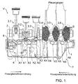
- Figur 1
- zeigt eine Schnittansicht einer Schottwandkonstruktion und einer Flüssigkeitsauffangvorrichtung gemäß einer Ausführungsform der Erfindung,
- Figur 2
- zeigt eine andere Schnittansicht der Schottwandkonstruktion und der Auffangvorrichtung,
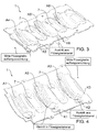
- Figur 3
- zeigt eine perspektivische Ansicht einer Schottwandkonstruktion gemäß einer Ausführungsform der Erfindung,
- Figur 4
- zeigt eine perspektivische Ansicht einer Schottwandkonstruktion gemäß einer Ausführungsform der Erfindung,
- Figur 5
- zeigt eine Schnittansicht der Schottwandkonstruktion und der Flüssigkeitsauffangvorrichtung der
Figuren 1 und2 , - Figur 6
- zeigt eine schematische Ansicht eines Flüssigkeitskanals und einer Pleuel-Geige mit Aufmaß bzw. einer Ausformung gemäß einer Ausführungsform der Erfindung,
- Figur 7
- zeigt eine perspektivische Ansicht der Schottwandkonstruktion und der Flüssigkeitsauffangvorrichtung, und
- Figur 8
- zeigt eine schematische Schnittansicht der Schottwandkonstruktion und der Flüssigkeitsauffangvorrichtung.
-
Figur 1 zeigt eine Flüssigkeitsauffangvorrichtung F mit einer Schottwandkonstruktion 1 für eine eine Kurbelwelle 2 und Pleuel 3.1 bis 3.6 umfassende Fahrzeugkonstruktion V. Die Flüssigkeitsauffangvorrichtung F ist insbesondere eine Ölauffangvorrichtung F, so dass die Figuren nachfolgend unter Bezugnahme auf Öl als Flüssigkeit beschrieben werden, die Erfindung hierauf aber nicht eingeschränkt ist. - Die Schottwandkonstruktion 1 ist als Deckeleinrichtung für die Olauffangvorrichtung F ausgeführt und unter der Kurbelwelle 2 und den Pleuel 3.1 bis 3.6 angeordnet.
- Die Olauffangvorrichtung F umfasst unter der Schottwandkonstruktion 1 eine Ölwanne 4 zur Aufnahme von Öl aus der Fahrzeugkonstruktion V. Die Ölwanne 4 umfasst einen Ölabsaugbereich 5, aus dem Öl über eine Ölpumpe 6 mittels eines im Ölabsaugbereich 5 angeordneten Ölsaugkorbs abgepumpt werden kann.
- Die Schottwandkonstruktion 1 ist aus zwei separaten Schottwandelementen ausgeführt, in
Figur 1 einem linken Schottwandelement und einem rechten Schottwandelement. Die Schottwandelemente sind vorzugsweise symmetrisch zueinander ausgeführt. - Die Schottwandkonstruktion 1 umfasst mehrere Ölkanäle K1, K2, K3, K4, K5 und K6 und mehrere Ausformungen A1, A2, A3, A4, A5 und A6 für sich drehende, zweckmäßig untere, insbesondere unterste Kurbelwellen- und/oder Pleuelabschnitte. Pro Pleuel 3.1 bis 3.6 und somit pro Kurbelwellen- und/oder Pleuelabschnitt ist jeweils eine Ausformung A1 bis A6 vorgesehen.
- Die Ausformungen A1 bis A6 sind so ausgeformt, dass mittels der Drehbewegung der Kurbelwellen- und/oder Pleuelabschnitte Öl aus den Ausformungen A1 bis A6 in die Flüssigkeitskanäle K1 bis K6 beaufschlagt wird, so dass eine Ölförderung von Ausformung zu Ausformung hin zum Ölabsaugbereich 5 erzielt wird.
- Insbesondere wird Öl aus der Ausformung A1 über den Flüssigkeitskanal K1 zur Ausformung A2 beaufschlagt, Öl aus der Ausformung A2 über den Flüssigkeitskanal K2 zur Ausformung A3 beaufschlagt und Öl aus der Ausformung A3 über den Flüssigkeitskanal K3 hin zum Ölabsaugbereich 5 befördert.
- Insbesondere wird Öl aus der Ausformung A6 über den Flüssigkeitskanal K6 zur Ausformung A5 beaufschlagt, Öl aus der Ausformung A5 über den Flüssigkeitskanal K5 zur Ausformung A4 beaufschlagt und Öl aus der Ausformung A4 über den Flüssigkeitskanal K4 hin zum Ölabsaugbereich 5 befördert.
- Daraus ergibt sich, dass im Rahmen der Erfindung eine Flüssigkeitsförderung von Ausformung zu Ausformung hin zum Ölabsaugbereich 5 darstellbar ist.
- Die Schottwandkonstruktion 1 kann folglich zusammen mit den sich drehenden Kurbelwellen- und/oder Pleuelabschnitten eine integrierte Ölförderfunktion erfüllen.
- Zwischen den Ausformungen A1 bis A6 und den sich drehenden Kurbelwellen- und/oder Pleuelabschnitten wird zweckmäßig ein Spalt S zur Ölaufnahme zwischen den Ausformungen A1 bis A6 und den sich drehenden Kurbelwellen- und/oder Pleuelabschnitten ausgebildet. Es versteht sich, dass zweckmäßig pro Pleuel 3.1 bis 3.6 und/oder pro Ausformung A1 bis A6 jeweils ein Spalt S ausgebildet wird. Die Spalte S können gleich oder verschieden dimensioniert sein.
- Die Ausformungen A1 bis A6 sind insbesondere gemäß der Hüllgeometrie der Drehbewegung der Kurbelwellen- und/oder Pleuelabschnitte ausgebildet, zusätzlich einem Abstandsmaß zur Ausbildung des Spalts S. Daraus folgt, dass die Ausformungen A1 bis A6 die Hüllgeometrie einer Kurbelwellenrotationsbewegung abbilden, zuzüglich einem definierten Abstand zur Ausbildung des Spalts S.
- Mittels der Drehbewegung der Kurbelwellen- und/oder Pleuelabschnitte kann Öl aus dem jeweiligen Spalt S in den jeweiligen Flüssigkeitskanal K1 bis K6 beaufschlagt werden.
- Der Ölsaugkorb im Ölabsaugbereich 5 hat ständig, insbesondere bei jeder Schräglage, unter dem Ölspiegel im Ölabsaugbereich 5 zu sein, ansonsten würde Luft angesaugt werden, so dass die Schmierung der Fahrzeugkonstruktion V (insbesondere des Motors) nicht mehr gewährleistet wäre.
- Die Ölförderung aus den Ausformungen A1 bis A6 und somit die Effektivität der in die Schottwandkonstruktion 1 integrierten Ölförderfunktion hängt insbesondere ab vom Spaltmaß des Spalts S (je kleiner der Spalt S, desto kleiner die Spaltverluste) und von den Durchlassquerschnitten der Ölkanäle K1 bis K6.
- Die Ölförderung aus den Ausformungen A1 bis A6 und somit die Effektivität der in die Schottwandkonstruktion 1 integrierten Ölförderfunktion ist ferner abhängig vom Betriebszustand der Fahrzeugvorrichtung V, insbesondere von der Motor- und/oder der Kurbelwellendrehzahl der Fahrzeugvorrichtung V.
- Befindet sich die Fahrzeugvorrichtung V in einer erhöhten Schräglage, sorgt die Ölförderfunktion dafür, dass eine ständige Ölförderung aus den Ausformungen A1 bis A6 zum Ölabsaugbereich 5 stattfindet, so dass die Gefahr einer Luftansaugung reduziert oder gar gänzlich vermieden werden kann.
-
Figur 2 zeigt eine andere Schnittansicht der Schottwandkonstruktion 1 und der Ölauffangvorrichtung F derFigur 1 , wobei zu Darstellungszwecken nicht alle Teile mit Bezugszeichen versehen sind. -
Figuren 3 und 4 zeigen eine Schottwandkonstruktion 1 gemäß einer Ausführungsform der Erfindung, die wie in denFiguren 1 und2 ausgeführt ist. -
Figur 3 zeigt insbesondere die Ausformungen A4 bis A6 und die zugehörigen Kanäle K4 bis K6, währendFigur 4 insbesondere die Ausformungen A1 bis A3 und die zugehörigen Kanäle K1 bis K3 zeigt. - Bezugszeichen 7 kennzeichnet optionale Aussparungen in der Schottwandkonstruktion 1 für die Kurbelwellenlagerung.
- Die Ölkanäle K3 und K4 sind sehr kurz ausgeführt und können im Rahmen der Erfindung als bloße Öldurchlassöffnung ausgeführt sein.
- Die
Figur 4 zeigt, dass ein Eintritt eines Ölkanals in einer Ausformung ausgebildet sein kann, der zugehörige Austritt aber nicht zwangsläufig in einer Ausformung ausgebildet sein muss, sondern auch benachbart dazu ausgebildet sein kann. In letztgenanntem Fall hat die Schottwandkonstruktion 1 zweckmäßig so ausgeführt zu sein, dass Öl aus dem Austritt in die zugehörige Ausformung fließen kann. Hierzu kann die Schottwandkonstruktion 1 z. B. einen Neigungsabschnitt hin zur zugehörigen. Ausformung aufweisen. -
Figur 5 zeigt eine Schnittansicht der Schottwandkonstruktion 1 und der Olauffangvorrichtung F nebst der Fahrzeugkonstruktion V derFiguren 1 und2 . - Aus
Figur 5 wird nochmals das Funktionsprinzip der Erfindung ersichtlich, nämlich, dass in der Schottwandkonstruktion eine Ausformung zur Aufnahme eines sich drehenden, unteren Kurbelwellen- und/oder Pleuelabschnitts ausgebildet ist und durch den sich drehenden Kurbelwellen- und/oder Pleuelabschnitt Öl aus der Ausformung, insbesondere aus dem Spalt zwischen der Ausformung und dem sich drehenden Kurbelwellen- und/oder Pleuelabschnitt, hinausbeförderbar ist, insbesondere in einen Ölkanal, so dass zweckmäßig eine Ölforderung hin zum Ölabsaugbereich ermöglicht wird. - Es versteht sich, dass im Rahmen der Erfindung pro Pleuel eine Ausformung vorgesehen ist.
-
Figur 6 zeigt eine schematische perspektivische Ansicht zweier benachbarter Ausformungen A6 und A5, insbesondere zweier Pleuel-Geigen mit Aufmaß. -
Figur 6 ist zunächst zu entnehmen, dass die Ölkanäle K6 und K5 zur Verbindung der zwei Ausformungen A6 und A5 dienen. Der Eintritt des Ölkanals K6 ist in der Ausformung A6 ausgebildet, dessen Austritt benachbart zur Ausformung A5. Der Eintritt des Ölkanals K5 ist in der Ausformung A5 ausgebildet, dessen Austritt kann in der Ausformung A4 oder benachbart dazu ausgebildet sein. -
Figur 6 zeigt darüber hinaus, dass der Durchlassquerschnitt der jeweiligen Ölkanäle K6 und K5 verjüngend ausgeführt ist und zwar in Öl-Förderrichtung, also von der Ausformung A6 zur Ausformung A5. Dadurch ist ein Druckunterschied und/oder eine Öl-Förderwirkung erzielbar. - Der sich verengende Durchlassquerschnitt führt zweckmäßig zu einer Beschleunigung des beförderten Öls. Der Ölmassenstrom am Austritt eines Ölkanals kann gegen die benachbarte Ausformung geworfen werden oder benachbart dazu ausströmen.
-
Figur 7 zeigt eine perspektivische Ansicht der Schottwandkonstruktion 1, der Ölauffangvorrichtung F und der Fahrzeugkonstruktion V mit der Kurbelwelle 2 und den Pleuel 3.1 bis 3.6. - Zu sehen ist nochmals, dass je Pleuel 3.1 bis 3.6 und somit je Pleuel- und/oder Kurbelwellenabschnitt je eine Ausformung A1 bis A6 in der Schottwandkonstruktion 1 ausgebildet ist. Ebenfalls ist je Ausformung A1 bis A6 je ein Ölkanal K1 bis K6 ausgebildet.
-
Figur 8 zeigt eine vereinfachte Schnittansicht zur nochmaligen Illustration des Funktionsprinzips der Erfindung. Zu sehen und benannt sind insbesondere die Kurbelwelle, ein Pleuel, ein Kurbelwellen- und/oder Pleuelabschnitt, insbesondere unterer, zweckmäßig unterster Kurbelwelle- und/oder Pleuelabschnitt, und eine Ausformung. - Die Erfindung ist nicht auf die oben beschriebenen bevorzugten Ausführungsformen beschränkt. Vielmehr ist eine Vielzahl von Varianten und Abwandlungen möglich, die ebenfalls von dem Erfindungsgedanken Gebrauch machen und somit in den Schutzbereich fallen. Darüber hinaus beansprucht die Erfindung auch Schutz für den Gegenstand und die Merkmale der Unteransprüche unabhängig von den in Bezug genommenen Merkmalen und Ansprüchen.
-
- 1
- Schottwandkonstruktion
- 2
- Kurbelwelle
- 3.1 bis 3.6
- Pleuel
- 4
- Flüssigkeits-Wanne
- 5
- Flüssigkeitsabsaugbereich
- 6
- Pumpeneinrichtung zum Absaugen von Flüssigkeit
- 7
- Aussparung für Kurbelwellenlagerung
- A1 bis A6
- Ausformungen, insbesondere Vertiefungen
- K1 bis K6
- Flüssigkeitskanäle
- F
- Flüssigkeitsauffangvorrichtung
- V
- Fahrzeugkonstruktion
Claims (17)
- Schottwandkonstruktion (1) für eine Flüssigkeitsauffangvorrichtung (F) für eine eine Kurbelwelle (2) und Pleuel (3.1 bis 3.6) umfassende Fahrzeug-Konstruktion (V), mit Flüssigkeitskanälen (K1 bis K6) und Ausformungen (A1 bis A6) für sich drehende Kurbelwellen- und/oder Pleuelabschnitte, wodurch Flüssigkeit aus den Ausformungen (A1 bis A6) hinaus beaufschlagbar ist.
- Schottwandkonstruktion (1) nach Anspruch 1, wobei Flüssigkeit über die Flüssigkeitskanäle (K1 bis K6) aus den Ausformungen (A1 bis A6) beaufschlagbar ist.
- Schottwandkonstruktion (1) nach Anspruch 1 oder 2, wobei zumindest ein Flüssigkeitskanal (K1, K2, K5, K6) eine Ausformung mit einer anderen Ausformung (A1-A2; A2-A3; A6-A5; A5-A4) verbindet, so dass vorzugsweise eine Flüssigkeitsförderung von Ausformung zu Ausformung (A1-A2; A2-A3; A6-A5; A5-A4) und/oder hin zu einem Flüssigkeitsabsaugbereich (5) ermöglicht wird.
- Schottwandkonstruktion (1) nach einem der vorhergehenden Ansprüche, wobei zumindest ein Flüssigkeitskanal (K3, K4) eine Ausformung (A3, A4) mit einem Flüssigkeitsabsaugbereich (5) verbindet, so dass vorzugsweise eine Flüssigkeitsförderung von Ausformung zu Ausformung (A1-A2; A2-A3; A6-A5; A5-A4) und/oder hin zu einem Flüssigkeitsabsaugbereich (5) ermöglicht wird.
- Schottwandkonstruktion (1) nach einem der vorhergehenden Ansprüche, wobei zumindest ein Flüssigkeitskanal (K1 bis K6) einen Flüssigkeitseintritt aufweist und der Flüssigkeitseintritt in einer Ausformung (A1 bis A6) oder benachbart dazu ausgebildet.
- Schottwandkonstruktion (1) nach einem der vorhergehenden Ansprüche, wobei zumindest ein Flüssigkeitskanal (K1 bis K6) einen Flüssigkeitsaustritt aufweist und der Flüssigkeitsaustritt in einer Ausformung (A1 bis A6) oder benachbart dazu ausgeführt ist.
- Schottwandkonstruktion (1) nach einem der vorhergehenden Ansprüche, wobei zumindest ein Flüssigkeitskanal (K1 bis K6) einen sich, vorzugsweise in Flüssikgeitsförderrichtung, verjüngenden Durchlassquerschnitt aufweist.
- Schottwandkonstruktion (1) nach einem der vorhergehenden Ansprüche, wobei ein Spalt (S) zur Flüssigkeitsaufnahme zwischen den Ausformungen (A1 bis A6) und den sich drehenden Kurbelwellen- und/oder Pleuelabschnitten ausgebildet wird.
- Schottwandkonstruktion (1) nach einem der vorhergehenden Ansprüche, wobei die Ausformungen (A1 bis A6) gemäß der Hüllgeometrie der Drehbewegung der Kurbelwellen- und/oder Pleuelabschnitte ausgebildet ist, zusätzlich einem Abstandmaß zur Ausbildung eines Spalts (S) zur Flüssigkeitsaufnahme zwischen den Ausformungen (A1 bis A6) und den sich drehenden Kurbelwellen- und/oder Pleuelabschnitten.
- Schottwandkonstruktion (1) nach Anspruch 8 oder 9, wobei der Spalt (S) ausgeführt ist, so dass mittels der Drehbewegung der Kurbelwellen- und/oder Pleuelabschnitte Flüssigkeit aus dem Spalt (S) in die Flüssigkeitskanäle (K1 bis K6) beaufschlagbar ist.
- Schottwandkonstruktion (1) nach einem der vorhergehenden Ansprüche, wobei die Flüssigkeit aus den Ausformungen (A1 bis A6) mittels der Drehbewegung der Kurbelwellen- und/oder Pleuelabschnitte in die Flüssigkeitskanäle (K1 bis K6) beaufschlagbar ist.
- Schottwandkonstruktion (1) nach einem der vorhergehenden Ansprüche, wobei die Schottwandkonstruktion (1) zur Anordnung unter die Fahrzeug-Konstruktion (V) ausgeführt ist und/oder zur Ausbildung einer Deckeleinrichtung für die Flüssigkeitsauffangvorrichtung (F) ausgeführt ist.
- Schottwandkonstruktion (1) nach einem der vorhergehenden Ansprüche, wobei die Schottwandkonstruktion (1) als Formteil, vorzugsweise Kunststoffformteil, mit integrierten Ausformungen (A1 bis A6) und/oder integrierten Flüssigkeitskanälen (K1 bis K6) ausgebildet ist.
- Flüssigkeitsauffangvorrichtung (F) für eine eine Kurbelwelle (2) und Pleuel (3.1 bis 3.6) umfassende Fahrzeug-Konstruktion (V), mit einer Schottwandkonstruktion (1) nach einem der vorhergehenden Ansprüche.
- Flüssigkeitsauffangvorrichtung (F) nach Anspruch 14, wobei die Flüssigkeitsauffangvorrichtung (F) eine Flüssigkeits-Wanne (4) zur Flüssigkeitsaufnahme mit einem Flüssigkeitsabsaugbereich (5) aufweist und vorzugsweise der Flüssigkeitsabsaugbereich (5) im Wesentlichen in der Mitte der Flüssigkeits-Wanne (4) angeordnet ist.
- Flüssigkeitsauffangvorrichtung (F) nach Anspruch 14 oder 15, wobei die Flüssigkeitsauffangvorrichtung (F) eine Pumpeneinrichtung (6) zum Absaugen der Flüssigkeit aus dem Flüssigkeitsabsaugbereich (5) aufweist.
- Anordnung, aufweisend eine eine Kurbelwelle (2) und Pleuel (3.1 bis 3.6) umfassende Fahrzeug-Konstruktion (V) und eine Flüssigkeitsauffangvorrichtung (F) nach einem der Ansprüche 14 bis 16.
Applications Claiming Priority (1)
| Application Number | Priority Date | Filing Date | Title |
|---|---|---|---|
| DE102015007909.3A DE102015007909A1 (de) | 2015-06-20 | 2015-06-20 | Schottwandkonstruktion mit integrierter Flüssigkeitsförderfunktion |
Publications (2)
| Publication Number | Publication Date |
|---|---|
| EP3106635A1 true EP3106635A1 (de) | 2016-12-21 |
| EP3106635B1 EP3106635B1 (de) | 2020-09-09 |
Family
ID=56344948
Family Applications (1)
| Application Number | Title | Priority Date | Filing Date |
|---|---|---|---|
| EP16001155.7A Active EP3106635B1 (de) | 2015-06-20 | 2016-05-20 | Schottwandkonstruktion mit integrierter flüssigkeitsförderfunktion |
Country Status (6)
| Country | Link |
|---|---|
| US (1) | US10502105B2 (de) |
| EP (1) | EP3106635B1 (de) |
| CN (1) | CN106256999B (de) |
| BR (1) | BR102016013954B1 (de) |
| DE (1) | DE102015007909A1 (de) |
| RU (1) | RU2720090C2 (de) |
Citations (4)
| Publication number | Priority date | Publication date | Assignee | Title |
|---|---|---|---|---|
| US6729292B1 (en) * | 1999-10-06 | 2004-05-04 | Daimlerchrysler Ag | Oil deflector in an oil pan for an internal combustion engine |
| EP1892390A2 (de) * | 2006-07-31 | 2008-02-27 | Dr.Ing.h.c. F. Porsche Aktiengesellschaft | Brennkraftmaschine |
| DE102008060412A1 (de) * | 2008-11-28 | 2010-06-02 | Dr. Ing. H.C. F. Porsche Aktiengesellschaft | Verbrennungsmotor |
| JP2010151011A (ja) * | 2008-12-25 | 2010-07-08 | Nissan Motor Co Ltd | 車両用エンジンのバッフルプレート |
Family Cites Families (19)
| Publication number | Priority date | Publication date | Assignee | Title |
|---|---|---|---|---|
| US2093570A (en) * | 1931-06-01 | 1937-09-21 | Continental Motors Corp | Engine |
| US4270497A (en) * | 1979-08-22 | 1981-06-02 | Valerio Robert M | Oil pan for internal combustion engines |
| DE3334044C2 (de) * | 1983-09-21 | 1985-11-07 | Audi AG, 8070 Ingolstadt | Hubkolben-Brennkraftmaschine |
| SU1312198A1 (ru) * | 1985-01-02 | 1987-05-23 | Алтайский тракторный завод им.М.И.Калинина | Устройство дл регулировани уровн масла в трансмиссии транспортного средства |
| DE3805708C1 (de) * | 1988-02-24 | 1989-03-30 | Mtu Friedrichshafen Gmbh | |
| JPH078804Y2 (ja) * | 1989-04-14 | 1995-03-06 | 日産自動車株式会社 | エンジンのオイルパン |
| US5190121A (en) * | 1991-10-31 | 1993-03-02 | General Motors Corporation | Two phase compressor lubrication |
| DE4139195C2 (de) | 1991-11-28 | 1999-05-27 | Audi Ag | Ölwannen-Einsatz |
| US6076495A (en) * | 1996-04-08 | 2000-06-20 | Sanshin Kogyo Kabushiki Kaisha | Bearing arrangement for vertical engine |
| US6286476B1 (en) * | 1996-04-30 | 2001-09-11 | Sanshin Kogyo Kabushiki Kaisha | Engine lubricating system |
| JP4063401B2 (ja) * | 1998-05-27 | 2008-03-19 | ヤマハマリン株式会社 | 船外機におけるエンジン用オイルポンプ構造 |
| JP4236354B2 (ja) * | 1999-11-19 | 2009-03-11 | 本田技研工業株式会社 | ドライサンプ式エンジンの潤滑装置 |
| US6786188B1 (en) * | 2003-05-15 | 2004-09-07 | Kawasaki Jukogyo Kabushiki Kaisha | Dry-sump lubrication type four-stroke cycle engine |
| JP2005127149A (ja) | 2003-10-21 | 2005-05-19 | Toyota Motor Corp | オイルパン用バッフルプレートの締結具および締結方法 |
| JP4523533B2 (ja) * | 2005-09-30 | 2010-08-11 | 本田技研工業株式会社 | 小型車両用エンジンの潤滑装置 |
| JP4861264B2 (ja) * | 2007-07-17 | 2012-01-25 | 株式会社東芝 | 光情報記録装置 |
| JP4516614B2 (ja) * | 2008-02-29 | 2010-08-04 | トヨタ自動車株式会社 | エンジンの潤滑装置 |
| DE102010055189B4 (de) * | 2010-12-20 | 2023-11-09 | Volkswagen Aktiengesellschaft | Ölhobel sowie Verbrennungsmotor mit Ölhobel |
| US9457881B1 (en) * | 2013-03-15 | 2016-10-04 | Brunswick Corporation | Outboard marine engines having a bedplate and cover assembly |
-
2015
- 2015-06-20 DE DE102015007909.3A patent/DE102015007909A1/de not_active Withdrawn
-
2016
- 2016-05-20 EP EP16001155.7A patent/EP3106635B1/de active Active
- 2016-06-16 BR BR102016013954-6A patent/BR102016013954B1/pt active IP Right Grant
- 2016-06-17 RU RU2016124107A patent/RU2720090C2/ru active
- 2016-06-20 CN CN201610440611.7A patent/CN106256999B/zh active Active
- 2016-06-20 US US15/187,367 patent/US10502105B2/en active Active
Patent Citations (4)
| Publication number | Priority date | Publication date | Assignee | Title |
|---|---|---|---|---|
| US6729292B1 (en) * | 1999-10-06 | 2004-05-04 | Daimlerchrysler Ag | Oil deflector in an oil pan for an internal combustion engine |
| EP1892390A2 (de) * | 2006-07-31 | 2008-02-27 | Dr.Ing.h.c. F. Porsche Aktiengesellschaft | Brennkraftmaschine |
| DE102008060412A1 (de) * | 2008-11-28 | 2010-06-02 | Dr. Ing. H.C. F. Porsche Aktiengesellschaft | Verbrennungsmotor |
| JP2010151011A (ja) * | 2008-12-25 | 2010-07-08 | Nissan Motor Co Ltd | 車両用エンジンのバッフルプレート |
Also Published As
| Publication number | Publication date |
|---|---|
| US20160369671A1 (en) | 2016-12-22 |
| EP3106635B1 (de) | 2020-09-09 |
| CN106256999B (zh) | 2020-11-06 |
| RU2016124107A (ru) | 2017-12-21 |
| CN106256999A (zh) | 2016-12-28 |
| DE102015007909A1 (de) | 2016-12-22 |
| BR102016013954B1 (pt) | 2022-10-04 |
| RU2720090C2 (ru) | 2020-04-24 |
| US10502105B2 (en) | 2019-12-10 |
| BR102016013954A2 (pt) | 2016-12-27 |
Similar Documents
| Publication | Publication Date | Title |
|---|---|---|
| EP3652419B1 (de) | Zylinderkopfölabscheider für einen verbrennungsmotor (strömungsgeführter ölabscheider) | |
| DE102008060412B4 (de) | Verbrennungsmotor | |
| EP3298241B1 (de) | Ölgeschmierte drehschieber-vakuumpumpe mit ölabscheide- und wiederaufbereitungseinrichtung | |
| DE10029844B4 (de) | Brennkraftmaschine, insbesondere für Motorräder | |
| EP1892390B1 (de) | Brennkraftmaschine | |
| DE10323068A1 (de) | Flüssigkeitstank | |
| EP3273136B1 (de) | Vorrichtung zum leiten von schmiermittel aus einem schmiermittelsammelbehälter | |
| EP3482078B1 (de) | Ölgeschmierte drehschieber-vakuumpumpe | |
| DE202014004864U1 (de) | Eine Luft-Flüssigkeit-Abscheideeinrichtung und ein Reiniger mit der Luft-Flüssigkeit-Abscheideeinrichtung für harte Oberflächen | |
| DE10127820A1 (de) | Ölabscheidevorrichtung für Kurbelgehäusegase einer Verbrennungskraftmaschine | |
| DE102006038700B4 (de) | Vorrichtung zur Abscheidung von Flüssigkeiten aus Gasen | |
| EP1878884A2 (de) | Ölauffangvorrichtung für eine Brennkraftmaschine | |
| EP3348804B1 (de) | Schmiermittelbehälter für ein hydrauliksystem | |
| DE102006002975B4 (de) | Entschäumungsvorrichtung für eine Flüssigkeit | |
| DE102015007909A1 (de) | Schottwandkonstruktion mit integrierter Flüssigkeitsförderfunktion | |
| DE102018213722A1 (de) | Ein behälter, ein verbrennungsmotor, ein fahrzeug und ein verfahren | |
| EP2423496A1 (de) | Zyklonabscheider mit horizontaler Zyklonachse | |
| DE102008060411B4 (de) | Verbrennungsmotor | |
| DE102013113611A1 (de) | Brennkraftmaschine mit einer Trockensumpfschmierung | |
| DE102013018166B4 (de) | Filtersystem mit Wasserauslassöffnung | |
| AT525580B1 (de) | Brennkraftmaschine mit zumindest einem zylinderkopf und zumindest einem kurbelgehäuse | |
| DE102022105977B4 (de) | Schmiermittelbehälter für eine Brennkraftmaschine sowie entsprechende Brennkraftmaschine | |
| DE102020104804B4 (de) | Fluidwanne mit quer zur Schwerkraft angeordneter Verbindungsleitung in Trennwand | |
| DE102021206930B4 (de) | Filter-Einrichtung | |
| DE102021201336B3 (de) | Fluidfördermodul, Fluidtank, der ein derartiges Fluidfördermodul aufweist, und Verfahren zum Betrieb eines Fluidfördermoduls |
Legal Events
| Date | Code | Title | Description |
|---|---|---|---|
| PUAI | Public reference made under article 153(3) epc to a published international application that has entered the european phase |
Free format text: ORIGINAL CODE: 0009012 |
|
| STAA | Information on the status of an ep patent application or granted ep patent |
Free format text: STATUS: THE APPLICATION HAS BEEN PUBLISHED |
|
| AK | Designated contracting states |
Kind code of ref document: A1 Designated state(s): AL AT BE BG CH CY CZ DE DK EE ES FI FR GB GR HR HU IE IS IT LI LT LU LV MC MK MT NL NO PL PT RO RS SE SI SK SM TR |
|
| AX | Request for extension of the european patent |
Extension state: BA ME |
|
| STAA | Information on the status of an ep patent application or granted ep patent |
Free format text: STATUS: REQUEST FOR EXAMINATION WAS MADE |
|
| 17P | Request for examination filed |
Effective date: 20170424 |
|
| RBV | Designated contracting states (corrected) |
Designated state(s): AL AT BE BG CH CY CZ DE DK EE ES FI FR GB GR HR HU IE IS IT LI LT LU LV MC MK MT NL NO PL PT RO RS SE SI SK SM TR |
|
| STAA | Information on the status of an ep patent application or granted ep patent |
Free format text: STATUS: EXAMINATION IS IN PROGRESS |
|
| 17Q | First examination report despatched |
Effective date: 20181121 |
|
| RAP1 | Party data changed (applicant data changed or rights of an application transferred) |
Owner name: MAN TRUCK & BUS SE |
|
| GRAP | Despatch of communication of intention to grant a patent |
Free format text: ORIGINAL CODE: EPIDOSNIGR1 |
|
| STAA | Information on the status of an ep patent application or granted ep patent |
Free format text: STATUS: GRANT OF PATENT IS INTENDED |
|
| INTG | Intention to grant announced |
Effective date: 20200324 |
|
| GRAJ | Information related to disapproval of communication of intention to grant by the applicant or resumption of examination proceedings by the epo deleted |
Free format text: ORIGINAL CODE: EPIDOSDIGR1 |
|
| STAA | Information on the status of an ep patent application or granted ep patent |
Free format text: STATUS: EXAMINATION IS IN PROGRESS |
|
| GRAR | Information related to intention to grant a patent recorded |
Free format text: ORIGINAL CODE: EPIDOSNIGR71 |
|
| GRAS | Grant fee paid |
Free format text: ORIGINAL CODE: EPIDOSNIGR3 |
|
| STAA | Information on the status of an ep patent application or granted ep patent |
Free format text: STATUS: GRANT OF PATENT IS INTENDED |
|
| INTC | Intention to grant announced (deleted) | ||
| GRAA | (expected) grant |
Free format text: ORIGINAL CODE: 0009210 |
|
| STAA | Information on the status of an ep patent application or granted ep patent |
Free format text: STATUS: THE PATENT HAS BEEN GRANTED |
|
| AK | Designated contracting states |
Kind code of ref document: B1 Designated state(s): AL AT BE BG CH CY CZ DE DK EE ES FI FR GB GR HR HU IE IS IT LI LT LU LV MC MK MT NL NO PL PT RO RS SE SI SK SM TR |
|
| INTG | Intention to grant announced |
Effective date: 20200804 |
|
| REG | Reference to a national code |
Ref country code: GB Ref legal event code: FG4D Free format text: NOT ENGLISH |
|
| REG | Reference to a national code |
Ref country code: AT Ref legal event code: REF Ref document number: 1311837 Country of ref document: AT Kind code of ref document: T Effective date: 20200915 Ref country code: CH Ref legal event code: EP |
|
| REG | Reference to a national code |
Ref country code: IE Ref legal event code: FG4D Free format text: LANGUAGE OF EP DOCUMENT: GERMAN |
|
| REG | Reference to a national code |
Ref country code: DE Ref legal event code: R096 Ref document number: 502016011067 Country of ref document: DE |
|
| REG | Reference to a national code |
Ref country code: NL Ref legal event code: FP |
|
| REG | Reference to a national code |
Ref country code: SE Ref legal event code: TRGR |
|
| REG | Reference to a national code |
Ref country code: LT Ref legal event code: MG4D |
|
| PG25 | Lapsed in a contracting state [announced via postgrant information from national office to epo] |
Ref country code: BG Free format text: LAPSE BECAUSE OF FAILURE TO SUBMIT A TRANSLATION OF THE DESCRIPTION OR TO PAY THE FEE WITHIN THE PRESCRIBED TIME-LIMIT Effective date: 20201209 Ref country code: HR Free format text: LAPSE BECAUSE OF FAILURE TO SUBMIT A TRANSLATION OF THE DESCRIPTION OR TO PAY THE FEE WITHIN THE PRESCRIBED TIME-LIMIT Effective date: 20200909 Ref country code: LT Free format text: LAPSE BECAUSE OF FAILURE TO SUBMIT A TRANSLATION OF THE DESCRIPTION OR TO PAY THE FEE WITHIN THE PRESCRIBED TIME-LIMIT Effective date: 20200909 Ref country code: GR Free format text: LAPSE BECAUSE OF FAILURE TO SUBMIT A TRANSLATION OF THE DESCRIPTION OR TO PAY THE FEE WITHIN THE PRESCRIBED TIME-LIMIT Effective date: 20201210 Ref country code: FI Free format text: LAPSE BECAUSE OF FAILURE TO SUBMIT A TRANSLATION OF THE DESCRIPTION OR TO PAY THE FEE WITHIN THE PRESCRIBED TIME-LIMIT Effective date: 20200909 Ref country code: NO Free format text: LAPSE BECAUSE OF FAILURE TO SUBMIT A TRANSLATION OF THE DESCRIPTION OR TO PAY THE FEE WITHIN THE PRESCRIBED TIME-LIMIT Effective date: 20201209 |
|
| PG25 | Lapsed in a contracting state [announced via postgrant information from national office to epo] |
Ref country code: RS Free format text: LAPSE BECAUSE OF FAILURE TO SUBMIT A TRANSLATION OF THE DESCRIPTION OR TO PAY THE FEE WITHIN THE PRESCRIBED TIME-LIMIT Effective date: 20200909 Ref country code: LV Free format text: LAPSE BECAUSE OF FAILURE TO SUBMIT A TRANSLATION OF THE DESCRIPTION OR TO PAY THE FEE WITHIN THE PRESCRIBED TIME-LIMIT Effective date: 20200909 Ref country code: PL Free format text: LAPSE BECAUSE OF FAILURE TO SUBMIT A TRANSLATION OF THE DESCRIPTION OR TO PAY THE FEE WITHIN THE PRESCRIBED TIME-LIMIT Effective date: 20200909 |
|
| PG25 | Lapsed in a contracting state [announced via postgrant information from national office to epo] |
Ref country code: EE Free format text: LAPSE BECAUSE OF FAILURE TO SUBMIT A TRANSLATION OF THE DESCRIPTION OR TO PAY THE FEE WITHIN THE PRESCRIBED TIME-LIMIT Effective date: 20200909 Ref country code: RO Free format text: LAPSE BECAUSE OF FAILURE TO SUBMIT A TRANSLATION OF THE DESCRIPTION OR TO PAY THE FEE WITHIN THE PRESCRIBED TIME-LIMIT Effective date: 20200909 Ref country code: SM Free format text: LAPSE BECAUSE OF FAILURE TO SUBMIT A TRANSLATION OF THE DESCRIPTION OR TO PAY THE FEE WITHIN THE PRESCRIBED TIME-LIMIT Effective date: 20200909 Ref country code: PT Free format text: LAPSE BECAUSE OF FAILURE TO SUBMIT A TRANSLATION OF THE DESCRIPTION OR TO PAY THE FEE WITHIN THE PRESCRIBED TIME-LIMIT Effective date: 20210111 Ref country code: CZ Free format text: LAPSE BECAUSE OF FAILURE TO SUBMIT A TRANSLATION OF THE DESCRIPTION OR TO PAY THE FEE WITHIN THE PRESCRIBED TIME-LIMIT Effective date: 20200909 |
|
| PG25 | Lapsed in a contracting state [announced via postgrant information from national office to epo] |
Ref country code: AL Free format text: LAPSE BECAUSE OF FAILURE TO SUBMIT A TRANSLATION OF THE DESCRIPTION OR TO PAY THE FEE WITHIN THE PRESCRIBED TIME-LIMIT Effective date: 20200909 Ref country code: ES Free format text: LAPSE BECAUSE OF FAILURE TO SUBMIT A TRANSLATION OF THE DESCRIPTION OR TO PAY THE FEE WITHIN THE PRESCRIBED TIME-LIMIT Effective date: 20200909 Ref country code: IS Free format text: LAPSE BECAUSE OF FAILURE TO SUBMIT A TRANSLATION OF THE DESCRIPTION OR TO PAY THE FEE WITHIN THE PRESCRIBED TIME-LIMIT Effective date: 20210109 |
|
| REG | Reference to a national code |
Ref country code: DE Ref legal event code: R097 Ref document number: 502016011067 Country of ref document: DE |
|
| PG25 | Lapsed in a contracting state [announced via postgrant information from national office to epo] |
Ref country code: SK Free format text: LAPSE BECAUSE OF FAILURE TO SUBMIT A TRANSLATION OF THE DESCRIPTION OR TO PAY THE FEE WITHIN THE PRESCRIBED TIME-LIMIT Effective date: 20200909 |
|
| PLBE | No opposition filed within time limit |
Free format text: ORIGINAL CODE: 0009261 |
|
| STAA | Information on the status of an ep patent application or granted ep patent |
Free format text: STATUS: NO OPPOSITION FILED WITHIN TIME LIMIT |
|
| 26N | No opposition filed |
Effective date: 20210610 |
|
| PG25 | Lapsed in a contracting state [announced via postgrant information from national office to epo] |
Ref country code: DK Free format text: LAPSE BECAUSE OF FAILURE TO SUBMIT A TRANSLATION OF THE DESCRIPTION OR TO PAY THE FEE WITHIN THE PRESCRIBED TIME-LIMIT Effective date: 20200909 Ref country code: SI Free format text: LAPSE BECAUSE OF FAILURE TO SUBMIT A TRANSLATION OF THE DESCRIPTION OR TO PAY THE FEE WITHIN THE PRESCRIBED TIME-LIMIT Effective date: 20200909 |
|
| REG | Reference to a national code |
Ref country code: CH Ref legal event code: PL |
|
| GBPC | Gb: european patent ceased through non-payment of renewal fee |
Effective date: 20210520 |
|
| PG25 | Lapsed in a contracting state [announced via postgrant information from national office to epo] |
Ref country code: CH Free format text: LAPSE BECAUSE OF NON-PAYMENT OF DUE FEES Effective date: 20210531 Ref country code: LU Free format text: LAPSE BECAUSE OF NON-PAYMENT OF DUE FEES Effective date: 20210520 Ref country code: MC Free format text: LAPSE BECAUSE OF FAILURE TO SUBMIT A TRANSLATION OF THE DESCRIPTION OR TO PAY THE FEE WITHIN THE PRESCRIBED TIME-LIMIT Effective date: 20200909 Ref country code: LI Free format text: LAPSE BECAUSE OF NON-PAYMENT OF DUE FEES Effective date: 20210531 |
|
| REG | Reference to a national code |
Ref country code: BE Ref legal event code: MM Effective date: 20210531 |
|
| PG25 | Lapsed in a contracting state [announced via postgrant information from national office to epo] |
Ref country code: IE Free format text: LAPSE BECAUSE OF NON-PAYMENT OF DUE FEES Effective date: 20210520 Ref country code: GB Free format text: LAPSE BECAUSE OF NON-PAYMENT OF DUE FEES Effective date: 20210520 |
|
| REG | Reference to a national code |
Ref country code: AT Ref legal event code: MM01 Ref document number: 1311837 Country of ref document: AT Kind code of ref document: T Effective date: 20210520 |
|
| PG25 | Lapsed in a contracting state [announced via postgrant information from national office to epo] |
Ref country code: BE Free format text: LAPSE BECAUSE OF NON-PAYMENT OF DUE FEES Effective date: 20210531 |
|
| PG25 | Lapsed in a contracting state [announced via postgrant information from national office to epo] |
Ref country code: AT Free format text: LAPSE BECAUSE OF NON-PAYMENT OF DUE FEES Effective date: 20210520 |
|
| PG25 | Lapsed in a contracting state [announced via postgrant information from national office to epo] |
Ref country code: HU Free format text: LAPSE BECAUSE OF FAILURE TO SUBMIT A TRANSLATION OF THE DESCRIPTION OR TO PAY THE FEE WITHIN THE PRESCRIBED TIME-LIMIT; INVALID AB INITIO Effective date: 20160520 |
|
| PG25 | Lapsed in a contracting state [announced via postgrant information from national office to epo] |
Ref country code: CY Free format text: LAPSE BECAUSE OF FAILURE TO SUBMIT A TRANSLATION OF THE DESCRIPTION OR TO PAY THE FEE WITHIN THE PRESCRIBED TIME-LIMIT Effective date: 20200909 |
|
| PG25 | Lapsed in a contracting state [announced via postgrant information from national office to epo] |
Ref country code: MK Free format text: LAPSE BECAUSE OF FAILURE TO SUBMIT A TRANSLATION OF THE DESCRIPTION OR TO PAY THE FEE WITHIN THE PRESCRIBED TIME-LIMIT Effective date: 20200909 |
|
| PG25 | Lapsed in a contracting state [announced via postgrant information from national office to epo] |
Ref country code: MT Free format text: LAPSE BECAUSE OF FAILURE TO SUBMIT A TRANSLATION OF THE DESCRIPTION OR TO PAY THE FEE WITHIN THE PRESCRIBED TIME-LIMIT Effective date: 20200909 |
|
| PGFP | Annual fee paid to national office [announced via postgrant information from national office to epo] |
Ref country code: NL Payment date: 20250526 Year of fee payment: 10 |
|
| PGFP | Annual fee paid to national office [announced via postgrant information from national office to epo] |
Ref country code: DE Payment date: 20250528 Year of fee payment: 10 |
|
| PGFP | Annual fee paid to national office [announced via postgrant information from national office to epo] |
Ref country code: IT Payment date: 20250522 Year of fee payment: 10 |
|
| PGFP | Annual fee paid to national office [announced via postgrant information from national office to epo] |
Ref country code: FR Payment date: 20250526 Year of fee payment: 10 |
|
| PGFP | Annual fee paid to national office [announced via postgrant information from national office to epo] |
Ref country code: SE Payment date: 20250526 Year of fee payment: 10 |
|
| PG25 | Lapsed in a contracting state [announced via postgrant information from national office to epo] |
Ref country code: TR Free format text: LAPSE BECAUSE OF FAILURE TO SUBMIT A TRANSLATION OF THE DESCRIPTION OR TO PAY THE FEE WITHIN THE PRESCRIBED TIME-LIMIT Effective date: 20200909 |