EP3104175A1 - Détermination d'analyte comprenant un remplissage partiel de bandelettes électrochimiques - Google Patents
Détermination d'analyte comprenant un remplissage partiel de bandelettes électrochimiques Download PDFInfo
- Publication number
- EP3104175A1 EP3104175A1 EP16175119.3A EP16175119A EP3104175A1 EP 3104175 A1 EP3104175 A1 EP 3104175A1 EP 16175119 A EP16175119 A EP 16175119A EP 3104175 A1 EP3104175 A1 EP 3104175A1
- Authority
- EP
- European Patent Office
- Prior art keywords
- current
- potential
- time
- electrodes
- switch
- Prior art date
- Legal status (The legal status is an assumption and is not a legal conclusion. Google has not performed a legal analysis and makes no representation as to the accuracy of the status listed.)
- Granted
Links
- 239000012491 analyte Substances 0.000 title claims abstract description 31
- 230000036961 partial effect Effects 0.000 title claims abstract description 16
- 238000005259 measurement Methods 0.000 claims abstract description 49
- 238000012360 testing method Methods 0.000 claims abstract description 36
- 238000000840 electrochemical analysis Methods 0.000 claims abstract description 22
- 230000008859 change Effects 0.000 claims abstract description 13
- 230000001419 dependent effect Effects 0.000 claims abstract description 9
- 238000000034 method Methods 0.000 claims description 37
- WQZGKKKJIJFFOK-GASJEMHNSA-N Glucose Natural products OC[C@H]1OC(O)[C@H](O)[C@@H](O)[C@@H]1O WQZGKKKJIJFFOK-GASJEMHNSA-N 0.000 claims description 33
- 239000008103 glucose Substances 0.000 claims description 33
- 238000012937 correction Methods 0.000 claims description 17
- QVGXLLKOCUKJST-UHFFFAOYSA-N atomic oxygen Chemical compound [O] QVGXLLKOCUKJST-UHFFFAOYSA-N 0.000 claims description 12
- 229910052760 oxygen Inorganic materials 0.000 claims description 12
- 239000001301 oxygen Substances 0.000 claims description 12
- 238000001514 detection method Methods 0.000 claims description 8
- 239000000654 additive Substances 0.000 claims description 6
- 230000000996 additive effect Effects 0.000 claims description 6
- 239000007788 liquid Substances 0.000 claims description 6
- 238000013213 extrapolation Methods 0.000 claims description 3
- 238000012544 monitoring process Methods 0.000 claims description 2
- 125000002791 glucosyl group Chemical group C1([C@H](O)[C@@H](O)[C@H](O)[C@H](O1)CO)* 0.000 claims 1
- 238000005534 hematocrit Methods 0.000 description 14
- 210000004369 blood Anatomy 0.000 description 10
- 239000008280 blood Substances 0.000 description 10
- 238000007599 discharging Methods 0.000 description 7
- VNWKTOKETHGBQD-UHFFFAOYSA-N methane Chemical compound C VNWKTOKETHGBQD-UHFFFAOYSA-N 0.000 description 7
- 238000013459 approach Methods 0.000 description 6
- 230000002829 reductive effect Effects 0.000 description 6
- 210000004027 cell Anatomy 0.000 description 5
- 150000002500 ions Chemical class 0.000 description 5
- 239000000243 solution Substances 0.000 description 5
- 239000000126 substance Substances 0.000 description 5
- 108090000790 Enzymes Proteins 0.000 description 4
- 102000004190 Enzymes Human genes 0.000 description 4
- 238000004458 analytical method Methods 0.000 description 4
- 238000013461 design Methods 0.000 description 4
- 238000009792 diffusion process Methods 0.000 description 4
- 229940088598 enzyme Drugs 0.000 description 4
- 238000004519 manufacturing process Methods 0.000 description 4
- 239000003153 chemical reaction reagent Substances 0.000 description 3
- 239000004020 conductor Substances 0.000 description 3
- 230000007423 decrease Effects 0.000 description 3
- 230000003247 decreasing effect Effects 0.000 description 3
- 210000003743 erythrocyte Anatomy 0.000 description 3
- 230000007246 mechanism Effects 0.000 description 3
- 230000008569 process Effects 0.000 description 3
- 238000001179 sorption measurement Methods 0.000 description 3
- 239000002800 charge carrier Substances 0.000 description 2
- 238000010586 diagram Methods 0.000 description 2
- 239000007772 electrode material Substances 0.000 description 2
- 238000003780 insertion Methods 0.000 description 2
- 230000037431 insertion Effects 0.000 description 2
- 230000010354 integration Effects 0.000 description 2
- 230000000670 limiting effect Effects 0.000 description 2
- 238000004313 potentiometry Methods 0.000 description 2
- 238000012545 processing Methods 0.000 description 2
- 238000011158 quantitative evaluation Methods 0.000 description 2
- 238000004064 recycling Methods 0.000 description 2
- 239000007787 solid Substances 0.000 description 2
- VEXZGXHMUGYJMC-UHFFFAOYSA-M Chloride anion Chemical compound [Cl-] VEXZGXHMUGYJMC-UHFFFAOYSA-M 0.000 description 1
- PHOQVHQSTUBQQK-SQOUGZDYSA-N D-glucono-1,5-lactone Chemical compound OC[C@H]1OC(=O)[C@H](O)[C@@H](O)[C@@H]1O PHOQVHQSTUBQQK-SQOUGZDYSA-N 0.000 description 1
- KCXVZYZYPLLWCC-UHFFFAOYSA-N EDTA Chemical compound OC(=O)CN(CC(O)=O)CCN(CC(O)=O)CC(O)=O KCXVZYZYPLLWCC-UHFFFAOYSA-N 0.000 description 1
- 108010015776 Glucose oxidase Proteins 0.000 description 1
- 239000004366 Glucose oxidase Substances 0.000 description 1
- 108090000854 Oxidoreductases Proteins 0.000 description 1
- 102000004316 Oxidoreductases Human genes 0.000 description 1
- 238000004082 amperometric method Methods 0.000 description 1
- 239000003146 anticoagulant agent Substances 0.000 description 1
- 229940127219 anticoagulant drug Drugs 0.000 description 1
- 230000008901 benefit Effects 0.000 description 1
- 238000009529 body temperature measurement Methods 0.000 description 1
- 239000003990 capacitor Substances 0.000 description 1
- 238000005119 centrifugation Methods 0.000 description 1
- 238000006243 chemical reaction Methods 0.000 description 1
- 238000012790 confirmation Methods 0.000 description 1
- 238000003869 coulometry Methods 0.000 description 1
- 206010012601 diabetes mellitus Diseases 0.000 description 1
- 229910003460 diamond Inorganic materials 0.000 description 1
- 239000010432 diamond Substances 0.000 description 1
- 230000000694 effects Effects 0.000 description 1
- 238000000835 electrochemical detection Methods 0.000 description 1
- 238000002848 electrochemical method Methods 0.000 description 1
- 230000005518 electrochemistry Effects 0.000 description 1
- 239000003792 electrolyte Substances 0.000 description 1
- 238000011156 evaluation Methods 0.000 description 1
- 238000002474 experimental method Methods 0.000 description 1
- YAGKRVSRTSUGEY-UHFFFAOYSA-N ferricyanide Chemical compound [Fe+3].N#[C-].N#[C-].N#[C-].N#[C-].N#[C-].N#[C-] YAGKRVSRTSUGEY-UHFFFAOYSA-N 0.000 description 1
- 235000012209 glucono delta-lactone Nutrition 0.000 description 1
- 229960003681 gluconolactone Drugs 0.000 description 1
- 229940116332 glucose oxidase Drugs 0.000 description 1
- 235000019420 glucose oxidase Nutrition 0.000 description 1
- PCHJSUWPFVWCPO-UHFFFAOYSA-N gold Chemical compound [Au] PCHJSUWPFVWCPO-UHFFFAOYSA-N 0.000 description 1
- 239000010931 gold Substances 0.000 description 1
- 229910052737 gold Inorganic materials 0.000 description 1
- 230000036571 hydration Effects 0.000 description 1
- 238000006703 hydration reaction Methods 0.000 description 1
- 238000012417 linear regression Methods 0.000 description 1
- 239000000463 material Substances 0.000 description 1
- 239000000203 mixture Substances 0.000 description 1
- 230000003472 neutralizing effect Effects 0.000 description 1
- 238000005457 optimization Methods 0.000 description 1
- 230000003647 oxidation Effects 0.000 description 1
- 238000007254 oxidation reaction Methods 0.000 description 1
- 230000009467 reduction Effects 0.000 description 1
- 230000027756 respiratory electron transport chain Effects 0.000 description 1
- 230000004044 response Effects 0.000 description 1
- 210000003296 saliva Anatomy 0.000 description 1
- 230000011664 signaling Effects 0.000 description 1
- 230000003068 static effect Effects 0.000 description 1
- 239000011550 stock solution Substances 0.000 description 1
- 230000001360 synchronised effect Effects 0.000 description 1
- 238000006276 transfer reaction Methods 0.000 description 1
- 210000002700 urine Anatomy 0.000 description 1
Images


Classifications
-
- G—PHYSICS
- G01—MEASURING; TESTING
- G01N—INVESTIGATING OR ANALYSING MATERIALS BY DETERMINING THEIR CHEMICAL OR PHYSICAL PROPERTIES
- G01N27/00—Investigating or analysing materials by the use of electric, electrochemical, or magnetic means
- G01N27/26—Investigating or analysing materials by the use of electric, electrochemical, or magnetic means by investigating electrochemical variables; by using electrolysis or electrophoresis
- G01N27/28—Electrolytic cell components
- G01N27/30—Electrodes, e.g. test electrodes; Half-cells
- G01N27/327—Biochemical electrodes, e.g. electrical or mechanical details for in vitro measurements
-
- G—PHYSICS
- G01—MEASURING; TESTING
- G01N—INVESTIGATING OR ANALYSING MATERIALS BY DETERMINING THEIR CHEMICAL OR PHYSICAL PROPERTIES
- G01N33/00—Investigating or analysing materials by specific methods not covered by groups G01N1/00 - G01N31/00
- G01N33/48—Biological material, e.g. blood, urine; Haemocytometers
- G01N33/483—Physical analysis of biological material
- G01N33/487—Physical analysis of biological material of liquid biological material
Definitions
- the present application relates to a method for determination of analyte that includes detecting partial fill in an electrochemical test strip.
- test strips are frequently used in the monitoring of blood glucose by diabetics. Such test strips can also be employed in the detection of other physiological chemicals of interest and substances of abuse.
- the test strip comprises at least two electrodes and appropriate reagents for the test to be performed, and is manufactured as a single use, disposable element.
- the test strip is combined with a sample such as blood, saliva or urine before or after insertion in a reusable meter, which contains the mechanisms for detecting and processing an electrochemical signal from the test strip into an indication of the presence/absence or quantity of the analyte determined by the test strip.
- US patent 4929426 discloses the use of an impedance electrode that sample flows over when the analysis chamber is filled
- US patent 5582697 , US patent 6212417 , and US patent 6299757 all disclose the use of a third electrode that can be used for fill detection.
- US patent 6743635 discloses a four electrodes approach, including separate fill detect anode and cathode.
- US patent 5997817 discloses a test strip with a window through which the sample can be viewed, and a "fill-to-here" line to assess sample sufficiency.
- US patent 6856125 discloses measurement of capacitance as a way to determine sample volume.
- the apparatus includes a sine wave generator to apply an AC signal to a biosensor cell containing a sample, a current-to-voltage converter, a phase shifter, a square wave generator, a synchronous demodulator, and a low pass filter which yields a signal proportional to the effective capacitance across the biosensor cell. This signal is proportional to the volume of the sample.
- electrochemical test strips are generally disposable and multiple strips may be used by a diabetic in a single day, it is desirable to control the cost of each item. It would therefore be desirable to have a system for confirming the sufficiency of sample volume without significantly adding to the component count in the test strip or the meter, and hence the manufacturing cost of the test strip and meter. It would further be desirable if such a system were automated within the test meter, and did not depend on an observation or judgment made by the user.
- the present invention provides an improved method of determining an analyte that includes detection of partial fill in an electrochemical test strip having electrodes and a liquid sample disposed between the electrodes by a method as defined in claim 1. Specifically, the method according to the invention comprises the steps of:
- Electrochemical detection of an analyte such as glucose is conventionally achieved by applying a potential to an electrochemical cell containing a sample to be evaluated for the presence/amount of glucose, an enzyme that oxidizes glucose, such as glucose oxidase, and a redox mediator.
- an enzyme that oxidizes glucose such as glucose oxidase
- a redox mediator As shown in Fig. 1 , the enzyme oxidizes glucose to form gluconolactone and a reduced form of the enzyme.
- Oxidized mediator reacts with the reduced enzyme to regenerate the active oxidase and produced a reduced mediator.
- Reduced mediator is oxidized at one of the electrodes, and electrochemical balance is maintained by a reducing reaction at the other electrode to result in a measurable current.
- the measured current is related to the amount of glucose in the sample, and various techniques are known for determining glucose concentrations in such a system. (See, for example, US Patents 6284125 ; 5942102 ; 53522351 ; and 5243516 .)
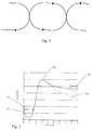
- Fig. 2 shows a theoretical plot of current, as a function of time after application of a potential in an electrochemical test strip for detection of glucose in which the test strip has facing working and counter electrodes, and the spacing of the electrodes is close together, such that recycling of mediator/charge carriers between the electrodes occurs, i.e., such that a shuttle current resulting from the oxidation and reduction of the mediator at the electrodes, independent of the presence of remaining analyte can be observed.
- the current trace shows an immediate initial current 21 on the time scale shown following application of the potential.
- This current is associated with the initial charging of the double layer and consumption of extraneous redox active species. Thereafter, the current decreases, because current is dependent on the mediator dissolving and then diffusing from the working electrode, where the reagents are deposited at the time of manufacture, to the counter electrode.
- the duration of this low current (indicated by arrow 20) is dependent on the rate at which the mediator dissolves, the distance between the electrodes and the effective distance that the mediator must travel to reach the counter electrode, and on the mobility of the mediator.
- Mediator mobility is a property of the mediator itself, i.e., the diffusion coefficient, but is also dependent on other sample properties such as hematocrit and viscosity.
- measurement of glucose or other analyte can be done during the initial voltage application, or based on a signal measured after the second application of voltage.
- Determination of glucose or other analytes in a sample can also be made using other electrochemical techniques. These include potentiometry, for example as described in US Patent 6251260 , or coulometry, for example as described in US Patent 6299757 .
- the present invention uses a determination of double layer capacitance to assess the sufficiency of sample volume introduced into an electrochemical test strip. Determination of double layer capacitance requires a knowledge of the current and the change in voltage as a function of time which can be obtained during either the charging or discharging of the double layer. Furthermore, the change in voltage can be viewed as a large, single-step change in voltage in which case an integral capacitance is obtained; or as a instantaneous change in voltage as a function of time, in which case a differential capacitance is obtained.
- double layer capacitance can be determined using any of three approaches which are summarized in Figs. 13A and B .
- Fig. 13A summarizes determination of capacitance from discharge charge
- Fig. 13B summarizes determination of capacitance from charging charge.
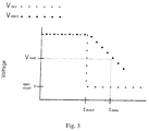
- Fig. 3 shows a plot of the applied voltage, V app , and the potential difference between the electrodes, V elect as a function of time. Initially, there is a constant voltage applied and a constant voltage at the electrode, and to a first approximation these two voltages are the same. At time t switch , the applied voltage is switched off.
- V elect begins to decay.
- the decay is monitored until a preselected threshold voltage is reached, and the time, t threshold is noted.
- the I in this formula is the current just before t switch , that is at a time before the voltage is switched off that is sufficiently close to t switch that the observed current is representative of the current in the instant prior to the voltage switch off.
- the actual time difference between the measurement and t switch can be on the order of 10 to 500 milliseconds, particularly if t switch falls in the plateau region where current is changing only slowly if at all.
- ⁇ V is the drop in voltage between the initial V elect which in a simple model may be assumed to be equal to the difference between V app and the threshold voltage V threshold .
- ⁇ t is the difference between t threshold and t switch .
- the capacitance determined in this way is related to the surface area of the electrodes or of the dominant electrode that is wetted by liquid sample such that a double layer can form.
- V threshold is determined based on the value of V app as well as an expected time course for the decay. If V threshold represents a large portion of V app , then the difference being measured is small, and the error is large. Further, as discussed below, in cases with resistive electrodes such as carbon electrodes there is an initial voltage drop, V drop , associated with the electrode resistance, and V threshold must be lower than V app - V drop . On the other hand, if V threshold is too low, then the time to take the measurement is longer, which is generally less acceptable from a user perspective.
- V threshold is suitably at least 30 mV below V app and no lower than 60 mV, preferably no lower than 120 mV, and more preferably at least 150 mV.
- V app is 300 mV and V threshold is selected as a voltage value between 150-240 mV.
- differential capacitance can be determined from the discharge cycle.
- the applied potential is switched off at time t switch .
- an instantaneous measurement of the slope of the voltage decay is determined.
- the time at which the measurement is made can be at a predetermined interval after t switch based on standard performance of a given strip design, for example between 1 and 500 msec after t swtich , or it may be determined based on the performance of the strip as it is used, in a manner comparable to taking a time measurement at V threshold as described above. This observation of the slope of the decay provide a value dV/dt.
- C dif I / dV / dt .
- the value for I in this equation may be the value of the current just before t switch as described above, or it may be the projected value for the current at the measurement time, using any of the models described above.
- Fig. 4 shows a plot of current as a function of time, when a potential is reapplied to the electrodes after t threshold is reached. Following reapplication of the potential, there is a second current spike 41 followed by a decay to a current value that is essentially equal to the projected current from before the applied potential is turned off.
- the shaded area 42 under the current curve can be determined by integration of the signal, or a representative portion thereof, or using a triangular approximation, and is indicative of the charging of the double layer. Theoretically, the discharge charge measured as described above in A and this charging charge should be equal. In practice, experimental differences are observed, but the charging charge can nonetheless be used separately, or as a confirmation of the discharge charge as an assessment of partial fill.
- the voltage reapplied is the same as the voltage that is initially applied.
- the reapplied voltage may also be greater or smaller than the initially applied voltage, provided it re-establishes the same diffusion limiting condition.
- the time interval over which the current measurements are made may be established statically, that is fixed based on strip design, or dynamically. In the case of a static definition of measurement time, it is desirable to start measuring the current at a time after the current spike, for example 1 to 10 msec after, to eliminate effects of circuit response/saturation. The ending time for the measurement is then a predefined interval of time, for example 100 -1000 msec.
- the end time may also be set as a multiple, for example an integer multiple, of ⁇ t from the discharge phase.
- the measurement interval may be equal to ⁇ t.
- the measurement time interval is determined based on characteristics of the measured current.
- measurement can be made until a predetermined drop in the excess current (I obs -I switch ) is achieved, for example more than 50%, preferably at least 75% and more preferably at least 90%, where I obs , is the current observed at any given time after t switch .
- Measurement can also continue until current has decreased to a level approaching I switch , for example 1.1 x I switch .
- V drop is a function of several factors, including the resistance of the electrode material and the connectors associated with the electrodes, fouling of the electrode and similar factors.
- the drop is larger with carbon electrodes than with a low resistance electrode such as one made of gold.
- the magnitude of V drop is taken into account in any of several ways.
- V threshold suitably depends on V drop .
- ⁇ V V app ⁇ V drop ⁇ V threshold .
- the voltage at which the measurement is taken can be described as ((V app -V drop ) minus a predetermined amount).
- the value of double layer capacitance can be corrected for the temperature of the sample, provided that the meter or the test strip is provided with means for determining this temperature.
- the temperature correction term, T-correction has the same form as described in commonly assigned US Patent Application No. 10/907790, filed April 15, 2005 , although in that application the correction term is used to correct the analyte concentration measurement.
- the temperature correction term can be assessed by any technique that gives a measure of oxygen carrying capacity, in combination with a temperature measurement for the sample.
- the present inventors have found that a graph of measured raw analyte concentration versus a measure of oxygen carrying capacity is a line with a slope that is dependent on the temperature at which the measurements are made, but that is independent of pO 2 and glucose concentration over normal ranges of values. Changes in pO 2 or glucose concentration result in an additive offset of the graphed lines, but not a change in slope.
- the temperature correction factor can be improved when there is a large body of data gathered at one temperature and a limited body of data gathered at the measurement temperature by determining only the slope from the data gathered at the measurement temperature and determining the intercept from all of the available data.
- the parameter I may be a constant established for the strip and meter combination, and only the slope needs to be determined experimentally.
- t mob a measure of the mobility of the mediator is used as the measure of oxygen carrying capacity.
- t mob is determined during the decay of the potential gradient following switching off of the potential. The decay in potential is monitored until the observed potential has decreased to a pre-determined value, V mob . Decreases to around 50 mV are convenient where the applied voltage is on the order of 300 mV, although somewhat smaller values such as 47 mV or 48 mV may be found to provide optimum results in particular experimental configurations. In general, V mob is suitably 0.025 to 0.1V.
- V mob is suitably in the range of 25 to 100 mV, preferably 45 to 50 mV.
- t mob is the time is takes after t switch for this voltage to be reached.
- determining a measure of the rate of decay may also be employed. For example, an instantaneous slope of the decay of the potential can be determined, or the decrease in voltage over a predetermined time can be used.
- the meter may also select a particular time window and perform a linear regression on V versus log(t) or In(t) to find t mob which is the time to a particular voltage. If the V mob does not fall within the selected window, a projection based on this linear fit can be used.
- the specific methodology is not critical, provided that the value of the measured decay is taken into account in determining the correction function.
- US Patents 6287451 and 6475372 disclose electrochemical methods for determination of hematocrit in a disposable test strip.
- the hematocrit measurement is used in a multiplicative correction, as opposed to the additive correction of the present invention.
- the measurement can be used in both modes, however, just as t mob is used for both types of corrections as described above. This is because hematocrit is a measure of the red blood cells, and red blood cells have an oxygen carrying capacity.
- hematocrit measurement is a measure of oxygen carrying capacity in present invention.
- a series of calibration measurements are taken to obtain data point pairs of uncorrected analyte concentration and hematocrit at each of a plurality of temperatures.
- the data points are fit to a linear model and the slope of the line is determined.
- this slope is independent of glucose and pO 2 such that while these parameters need to be kept the same across experiments, the particular values are not significant.
- the resulting slope/temperature data point pairs are then fitted to a linear model, to determine the slope and intercept which is incorporated into an additive correction factor as described above.
- the linear model may be sufficient only for a narrow range of the data.
- An improved additive correction factor may be determined for a wider range of temperatures or oxygen carrying capacities by introducing non-linear terms such as quadratic equations of exponents to terms.
- the meter first acts in an amperometric mode, and then after the applied potential is switched off, in a potentiometric mode.
- a potentiometric mode In order to enhance the quality and consistency of measurements made when operating in potentiometric mode, if is desirable to perform the switch to potentiometric mode only after a stable diffusion gradient of oxidized and reduced mediator has formed within the electrochemical test cell. In general, the potentiometry measurements will give the same stable reading at any point after the concentration gradients have formed a stable profile that extends "far enough" into the bulk of the sample.
- t switch can be determined dynamically.
- t switch is determined dynamically from the determined value of t peak (the time of peak 22, in Fig.2 ) by adding a time interval, for example 2 to 3 seconds to the determined value of t peak .
- t switch is determined dynamically using a fixed value of t switch when t peak is small and t peak plus a predetermined amount when t peak is larger.
- t switch may have a fixed value of 3.5 second when t peak is less than 1.5 seconds, and be equal to t peak plus an offset (for example 2 second) when t peak is greater than 1.5 seconds.
- a third mode for measurement is established for circumstances when t peak occurs at times that are longer than ordinary.
- t peak occurs above a predetermined threshold, for example 5 seconds
- t switch is suitably determined as a function of t peak and an additive correction factor that uses predetermined constants derived from the slope of the Cottrell current.
- the method of the invention can be used with any strip that has facing electrodes, providing that a meter apparatus is provided that can receive the strip and provide the necessary applications of voltage and signal processing.
- Fig. 6 shows an external view of a meter for use in accordance with the invention.
- the meter has a housing 61, and a display 62.
- the housing 61 has a slot 63, into which a test strip is inserted for use.
- the meter may also have a button 64 for signaling the start of the measurement cycle, or may have an internal mechanism for detecting the insertion of a test strip or the application of a sample.
- Such mechanisms are known in the art, for example from US Patents 5266179 ; 5320732 ; 5438271 and 6616819 .
- buttons, displays such as LCD displays, RF, infrared or other wireless transmitters, wire connectors such as USB, parallel or serial connections constitute means for receiving input from and communicating a result to a user, and can be used individually and in various combinations.
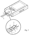
- Fig. 7 shows an interior view in which the connection of the meter to a test strip is shown.
- the test strip 71 has contacts 72, 73 by which the electrodes are placed in electrical contact with contacts 74, 75 of the meter.
- the means for making a DC determination of double layer capacitance comprises circuits, such as on a circuit board associated with a programmed microprocessor that interacts with the circuits to provide the desired switching between amperometric and potentiometric modes and to monitor curreent and voltage as described.
- Apparatus suitable for switching between an amperometric mode of operation in which current is measured and a potentiometric mode of operation in which a potential difference between the electrodes is measured are described in US Provisional Applications Nos. 60/521,592, filed May 30, 2004 , and 60/594,285 filed March 25, 2005 .
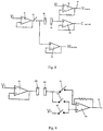
- Fig. 8 shows an electrical schematic of a meter for use according to the invention.
- Working electrode 80 is connected to op amp 81 via a connector containing switch 82, and to op amp 83.
- Counter electrode 84 is connected to op amps 85 and 86.
- Op amps 83, 85 and 86 are high impedance input amplifiers.
- the resulting potential difference between the electrodes results in the generation of a current that is related to the amount of analyte, and this current can be monitored at output 87 and converted to an indication of the presence or amount of analyte.
- switch 82 is opened to create an open circuit and stop application of the potential difference, current flow ceases, and the output of amplifier 86 assumes the potential of the counter electrode, while the output of amplifier 83 assumes the potential of the working electrode 80.
- the difference between the output from op amp 83 and op amp 86 indicates the decay in chemical potential and is processed in accordance with the methods described above to create an indication of partial fill.
- Fig. 9 shows an alternative version of this circuit using only two op amps and an increased number of switches.
- Working electrode 80 is connected to op amp 81 which received input voltage V 2 .
- Counter electrode 84 is connected to high input impedance op amp 90 via one of two switched paths.
- Input voltage V 1 is connected to the circuit via a third switched path.
- switch 91 and 93 are closed, and switch 92 is open, the circuit functions in amperometric mode, and the output at 95 reflects current flow at the electrodes.
- switch 92 is closed, and switches 91 and 93 are open, the circuit operates in potentiometric mode and the output at 95 assumes the potential of the counter electrode (similar to amplifier 86 in Fig. 8 ).
- the output at 95 indirectly reflects the difference in potential between the electrodes.
- the actual difference in potential between the electrodes is the difference between the output at 95, and the output of op amp 81 (at 80, the working electrode).
- a signal to the user indicating incomplete fill is suitably generated when the measured value of the double layer capacitance is below the pre-determined level.
- the sample applied to the test strips could be a blood sample.
- a control solution containing a charge carrier for example a mixture of ferrocyanide and ferricyanide.
- the "variability" of the measured double layer capacitance can be determined using any acceptable mathematical analysis. For example, variability can be indicated by the range of measured values, or the standard deviation of the measured values.
- the differential capacitance for a given sample/test strip varies significantly with the potential at which it is measured. Further, the graph shows a region 100 in which the change in C dif with voltage is less, and it is in this region of voltage difference in which measurements for determination of C dif are preferably made.
- 300 mV was applied to electrochemical test strips with blood samples having either 2.79 mM or 20.2 mM glucose until a plateau current was observed. The applied voltage was then switched off, and the charge passed in discharging the double layer from 250 mV to 150 mV was measured. 300 mV was then reapplied, and the charge passed to recharge the double layer to 250 mV was observed.
- the relationship between the charging and discharging current was observed to be substantially linear with a zero intercept. However, the charge determined for recharging was lower than that for discharging, indicating that the measurement time of 100 ms was not sufficient for the recharging double layer to fully equilibrate with the solution. The observed amounts of charge were independent of glucose concentration, although the higher concentration decayed markedly faster.
- the horizontal line in Fig. 11 is a threshold level of differential capacitance set at 1.7 ⁇ F that could be used with this test strip in assessing sample sufficiency. As shown, all of the filled samples resulted in a capacitance above this threshold, while only three of the partial fills would have given a false acceptance.
- Fig. 12 shows results for the ten lots, plotting differential capacitance versus time for a decay to 50 mV. Two things are observable from this graph. First, for 8 of the ten lots, differential capacitance is fairly constant, although the time to reach the 50 mV drop is variable. This argues in favour of dynamically determining the time of measurement, but exhibits the general robustness of the technique. The two lots that deviated from the other 8 also display a fairly constant level of capacitance, and very little variation in time to 50 mV. It was determined that in these lots the carbon electrodes were screen printed using a different technique. Thus, the cut off established for capacitance to account for partial fill can account for lot-to-lot variation with a consistent manufacturing technique, but may need to be reset where changes in manufacturing techniques are changed.
Landscapes
- Health & Medical Sciences (AREA)
- Life Sciences & Earth Sciences (AREA)
- Chemical & Material Sciences (AREA)
- Physics & Mathematics (AREA)
- Pathology (AREA)
- Molecular Biology (AREA)
- Engineering & Computer Science (AREA)
- Analytical Chemistry (AREA)
- Biochemistry (AREA)
- General Health & Medical Sciences (AREA)
- General Physics & Mathematics (AREA)
- Immunology (AREA)
- Electrochemistry (AREA)
- Chemical Kinetics & Catalysis (AREA)
- Biomedical Technology (AREA)
- Biophysics (AREA)
- Hematology (AREA)
- Urology & Nephrology (AREA)
- Food Science & Technology (AREA)
- Medicinal Chemistry (AREA)
- Investigating Or Analyzing Materials By The Use Of Electric Means (AREA)
- Investigating Or Analysing Biological Materials (AREA)
Applications Claiming Priority (3)
| Application Number | Priority Date | Filing Date | Title |
|---|---|---|---|
| US10/907,813 US7547382B2 (en) | 2005-04-15 | 2005-04-15 | Determination of partial fill in electrochemical strips |
| EP15160465.9A EP2908130B1 (fr) | 2005-04-15 | 2006-04-15 | Contrôle de qualité de bandes d'essai électrochimiques |
| EP06727948.9A EP1869453B1 (fr) | 2005-04-15 | 2006-04-15 | Determination de remplissage partiel de bandelettes electrochimiques |
Related Parent Applications (2)
| Application Number | Title | Priority Date | Filing Date |
|---|---|---|---|
| EP15160465.9A Division EP2908130B1 (fr) | 2005-04-15 | 2006-04-15 | Contrôle de qualité de bandes d'essai électrochimiques |
| EP06727948.9A Division EP1869453B1 (fr) | 2005-04-15 | 2006-04-15 | Determination de remplissage partiel de bandelettes electrochimiques |
Publications (2)
| Publication Number | Publication Date |
|---|---|
| EP3104175A1 true EP3104175A1 (fr) | 2016-12-14 |
| EP3104175B1 EP3104175B1 (fr) | 2017-11-15 |
Family
ID=37087419
Family Applications (3)
| Application Number | Title | Priority Date | Filing Date |
|---|---|---|---|
| EP06727948.9A Active EP1869453B1 (fr) | 2005-04-15 | 2006-04-15 | Determination de remplissage partiel de bandelettes electrochimiques |
| EP15160465.9A Active EP2908130B1 (fr) | 2005-04-15 | 2006-04-15 | Contrôle de qualité de bandes d'essai électrochimiques |
| EP16175119.3A Active EP3104175B1 (fr) | 2005-04-15 | 2006-04-15 | Détermination d'analyte comprenant un remplissage partiel de bandelettes électrochimiques |
Family Applications Before (2)
| Application Number | Title | Priority Date | Filing Date |
|---|---|---|---|
| EP06727948.9A Active EP1869453B1 (fr) | 2005-04-15 | 2006-04-15 | Determination de remplissage partiel de bandelettes electrochimiques |
| EP15160465.9A Active EP2908130B1 (fr) | 2005-04-15 | 2006-04-15 | Contrôle de qualité de bandes d'essai électrochimiques |
Country Status (9)
| Country | Link |
|---|---|
| US (1) | US7547382B2 (fr) |
| EP (3) | EP1869453B1 (fr) |
| JP (1) | JP2008536139A (fr) |
| KR (1) | KR101289757B1 (fr) |
| CN (1) | CN101198868A (fr) |
| AU (1) | AU2006233770B2 (fr) |
| CA (1) | CA2604374C (fr) |
| ES (1) | ES2546455T3 (fr) |
| WO (1) | WO2006109277A2 (fr) |
Families Citing this family (97)
| Publication number | Priority date | Publication date | Assignee | Title |
|---|---|---|---|---|
| US6036924A (en) | 1997-12-04 | 2000-03-14 | Hewlett-Packard Company | Cassette of lancet cartridges for sampling blood |
| US6391005B1 (en) | 1998-03-30 | 2002-05-21 | Agilent Technologies, Inc. | Apparatus and method for penetration with shaft having a sensor for sensing penetration depth |
| US8641644B2 (en) | 2000-11-21 | 2014-02-04 | Sanofi-Aventis Deutschland Gmbh | Blood testing apparatus having a rotatable cartridge with multiple lancing elements and testing means |
| CA2448902C (fr) | 2001-06-12 | 2010-09-07 | Pelikan Technologies, Inc. | Autopiqueur a optimisation automatique presentant des moyens d'adaptation aux variations temporelles des proprietes cutanees |
| US7981056B2 (en) | 2002-04-19 | 2011-07-19 | Pelikan Technologies, Inc. | Methods and apparatus for lancet actuation |
| US7041068B2 (en) | 2001-06-12 | 2006-05-09 | Pelikan Technologies, Inc. | Sampling module device and method |
| US9795747B2 (en) | 2010-06-02 | 2017-10-24 | Sanofi-Aventis Deutschland Gmbh | Methods and apparatus for lancet actuation |
| AU2002348683A1 (en) | 2001-06-12 | 2002-12-23 | Pelikan Technologies, Inc. | Method and apparatus for lancet launching device integrated onto a blood-sampling cartridge |
| US9427532B2 (en) | 2001-06-12 | 2016-08-30 | Sanofi-Aventis Deutschland Gmbh | Tissue penetration device |
| US9226699B2 (en) | 2002-04-19 | 2016-01-05 | Sanofi-Aventis Deutschland Gmbh | Body fluid sampling module with a continuous compression tissue interface surface |
| US7033371B2 (en) | 2001-06-12 | 2006-04-25 | Pelikan Technologies, Inc. | Electric lancet actuator |
| EP1404232B1 (fr) | 2001-06-12 | 2009-12-02 | Pelikan Technologies Inc. | Appareil de prelevement sanguin et procede connexe |
| DE60239132D1 (de) | 2001-06-12 | 2011-03-24 | Pelikan Technologies Inc | Gerät zur erhöhung der erfolgsrate im hinblick auf die durch einen fingerstich erhaltene blutausbeute |
| US8337419B2 (en) | 2002-04-19 | 2012-12-25 | Sanofi-Aventis Deutschland Gmbh | Tissue penetration device |
| US8260393B2 (en) | 2003-07-25 | 2012-09-04 | Dexcom, Inc. | Systems and methods for replacing signal data artifacts in a glucose sensor data stream |
| US8010174B2 (en) | 2003-08-22 | 2011-08-30 | Dexcom, Inc. | Systems and methods for replacing signal artifacts in a glucose sensor data stream |
| US7291117B2 (en) | 2002-04-19 | 2007-11-06 | Pelikan Technologies, Inc. | Method and apparatus for penetrating tissue |
| US7713214B2 (en) | 2002-04-19 | 2010-05-11 | Pelikan Technologies, Inc. | Method and apparatus for a multi-use body fluid sampling device with optical analyte sensing |
| US7175642B2 (en) | 2002-04-19 | 2007-02-13 | Pelikan Technologies, Inc. | Methods and apparatus for lancet actuation |
| US7648468B2 (en) | 2002-04-19 | 2010-01-19 | Pelikon Technologies, Inc. | Method and apparatus for penetrating tissue |
| US7901362B2 (en) | 2002-04-19 | 2011-03-08 | Pelikan Technologies, Inc. | Method and apparatus for penetrating tissue |
| US7717863B2 (en) | 2002-04-19 | 2010-05-18 | Pelikan Technologies, Inc. | Method and apparatus for penetrating tissue |
| US9795334B2 (en) | 2002-04-19 | 2017-10-24 | Sanofi-Aventis Deutschland Gmbh | Method and apparatus for penetrating tissue |
| US7331931B2 (en) | 2002-04-19 | 2008-02-19 | Pelikan Technologies, Inc. | Method and apparatus for penetrating tissue |
| US7297122B2 (en) | 2002-04-19 | 2007-11-20 | Pelikan Technologies, Inc. | Method and apparatus for penetrating tissue |
| US7232451B2 (en) | 2002-04-19 | 2007-06-19 | Pelikan Technologies, Inc. | Method and apparatus for penetrating tissue |
| US7892183B2 (en) | 2002-04-19 | 2011-02-22 | Pelikan Technologies, Inc. | Method and apparatus for body fluid sampling and analyte sensing |
| US8267870B2 (en) | 2002-04-19 | 2012-09-18 | Sanofi-Aventis Deutschland Gmbh | Method and apparatus for body fluid sampling with hybrid actuation |
| US7909778B2 (en) | 2002-04-19 | 2011-03-22 | Pelikan Technologies, Inc. | Method and apparatus for penetrating tissue |
| US8221334B2 (en) | 2002-04-19 | 2012-07-17 | Sanofi-Aventis Deutschland Gmbh | Method and apparatus for penetrating tissue |
| US7547287B2 (en) | 2002-04-19 | 2009-06-16 | Pelikan Technologies, Inc. | Method and apparatus for penetrating tissue |
| US7976476B2 (en) | 2002-04-19 | 2011-07-12 | Pelikan Technologies, Inc. | Device and method for variable speed lancet |
| US8579831B2 (en) | 2002-04-19 | 2013-11-12 | Sanofi-Aventis Deutschland Gmbh | Method and apparatus for penetrating tissue |
| US7229458B2 (en) | 2002-04-19 | 2007-06-12 | Pelikan Technologies, Inc. | Method and apparatus for penetrating tissue |
| US8784335B2 (en) | 2002-04-19 | 2014-07-22 | Sanofi-Aventis Deutschland Gmbh | Body fluid sampling device with a capacitive sensor |
| US7674232B2 (en) | 2002-04-19 | 2010-03-09 | Pelikan Technologies, Inc. | Method and apparatus for penetrating tissue |
| US7491178B2 (en) | 2002-04-19 | 2009-02-17 | Pelikan Technologies, Inc. | Method and apparatus for penetrating tissue |
| US8702624B2 (en) | 2006-09-29 | 2014-04-22 | Sanofi-Aventis Deutschland Gmbh | Analyte measurement device with a single shot actuator |
| US9248267B2 (en) | 2002-04-19 | 2016-02-02 | Sanofi-Aventis Deustchland Gmbh | Tissue penetration device |
| US9314194B2 (en) | 2002-04-19 | 2016-04-19 | Sanofi-Aventis Deutschland Gmbh | Tissue penetration device |
| US7371247B2 (en) | 2002-04-19 | 2008-05-13 | Pelikan Technologies, Inc | Method and apparatus for penetrating tissue |
| US8574895B2 (en) | 2002-12-30 | 2013-11-05 | Sanofi-Aventis Deutschland Gmbh | Method and apparatus using optical techniques to measure analyte levels |
| DK1633235T3 (da) | 2003-06-06 | 2014-08-18 | Sanofi Aventis Deutschland | Apparat til udtagelse af legemsvæskeprøver og detektering af analyt |
| WO2006001797A1 (fr) | 2004-06-14 | 2006-01-05 | Pelikan Technologies, Inc. | Element penetrant peu douloureux |
| US20080119703A1 (en) | 2006-10-04 | 2008-05-22 | Mark Brister | Analyte sensor |
| US20190357827A1 (en) | 2003-08-01 | 2019-11-28 | Dexcom, Inc. | Analyte sensor |
| US20140121989A1 (en) | 2003-08-22 | 2014-05-01 | Dexcom, Inc. | Systems and methods for processing analyte sensor data |
| US8282576B2 (en) | 2003-09-29 | 2012-10-09 | Sanofi-Aventis Deutschland Gmbh | Method and apparatus for an improved sample capture device |
| US9351680B2 (en) | 2003-10-14 | 2016-05-31 | Sanofi-Aventis Deutschland Gmbh | Method and apparatus for a variable user interface |
| US8364231B2 (en) | 2006-10-04 | 2013-01-29 | Dexcom, Inc. | Analyte sensor |
| WO2005057175A2 (fr) | 2003-12-09 | 2005-06-23 | Dexcom, Inc. | Traitement de signal pour capteur continu d'analyte |
| WO2005065414A2 (fr) | 2003-12-31 | 2005-07-21 | Pelikan Technologies, Inc. | Procede et appareil permettant d'ameliorer le flux fluidique et le prelevement d'echantillons |
| US7822454B1 (en) | 2005-01-03 | 2010-10-26 | Pelikan Technologies, Inc. | Fluid sampling device with improved analyte detecting member configuration |
| US8828203B2 (en) | 2004-05-20 | 2014-09-09 | Sanofi-Aventis Deutschland Gmbh | Printable hydrogels for biosensors |
| KR101328608B1 (ko) | 2004-05-21 | 2013-11-12 | 아가매트릭스, 인코포레이티드 | 전기화학 셀 및 전기화학 셀 제조 방법 |
| US9820684B2 (en) | 2004-06-03 | 2017-11-21 | Sanofi-Aventis Deutschland Gmbh | Method and apparatus for a fluid sampling device |
| US8652831B2 (en) | 2004-12-30 | 2014-02-18 | Sanofi-Aventis Deutschland Gmbh | Method and apparatus for analyte measurement test time |
| US20070152683A1 (en) * | 2005-12-30 | 2007-07-05 | Karl Werner | Electronic device for analysis of a body fluid |
| US9149215B2 (en) | 2005-12-30 | 2015-10-06 | Roche Diabetes Care, Inc. | Portable analytical device |
| US8114269B2 (en) * | 2005-12-30 | 2012-02-14 | Medtronic Minimed, Inc. | System and method for determining the point of hydration and proper time to apply potential to a glucose sensor |
| US8529751B2 (en) | 2006-03-31 | 2013-09-10 | Lifescan, Inc. | Systems and methods for discriminating control solution from a physiological sample |
| US7771583B2 (en) * | 2006-10-18 | 2010-08-10 | Agamatrix, Inc. | Electrochemical determination of analytes |
| US8778168B2 (en) | 2007-09-28 | 2014-07-15 | Lifescan, Inc. | Systems and methods of discriminating control solution from a physiological sample |
| US8603768B2 (en) * | 2008-01-17 | 2013-12-10 | Lifescan, Inc. | System and method for measuring an analyte in a sample |
| EP2265324B1 (fr) | 2008-04-11 | 2015-01-28 | Sanofi-Aventis Deutschland GmbH | Système intégré de mesure d'analytes |
| US8551320B2 (en) | 2008-06-09 | 2013-10-08 | Lifescan, Inc. | System and method for measuring an analyte in a sample |
| US9375169B2 (en) | 2009-01-30 | 2016-06-28 | Sanofi-Aventis Deutschland Gmbh | Cam drive for managing disposable penetrating member actions with a single motor and motor and control system |
| TWI388823B (zh) * | 2009-04-09 | 2013-03-11 | Bionime Corp | 一種判斷樣品佈滿狀況的偵測方法 |
| CN106053585A (zh) * | 2009-05-12 | 2016-10-26 | 华广生技股份有限公司 | 一种判断样品布满状况的侦测方法 |
| US9907499B2 (en) * | 2009-09-15 | 2018-03-06 | Agamatrix, Inc. | Implantable electrochemical biosensor system and method |
| IL209760A (en) | 2009-12-11 | 2015-05-31 | Lifescan Scotland Ltd | A system and method for measuring filling is satisfactory |
| US8101065B2 (en) * | 2009-12-30 | 2012-01-24 | Lifescan, Inc. | Systems, devices, and methods for improving accuracy of biosensors using fill time |
| US20110208435A1 (en) * | 2010-02-25 | 2011-08-25 | Lifescan Scotland Ltd. | Capacitance detection in electrochemical assays |
| EP2539711B1 (fr) * | 2010-02-25 | 2014-01-22 | Lifescan Scotland Limited | Détection de capacitance en analyse électrochimique |
| US8965476B2 (en) | 2010-04-16 | 2015-02-24 | Sanofi-Aventis Deutschland Gmbh | Tissue penetration device |
| ES2851336T3 (es) | 2010-09-17 | 2021-09-06 | Agamatrix Inc | Método y aparato para codificar tiras de ensayo |
| US8932445B2 (en) * | 2010-09-30 | 2015-01-13 | Cilag Gmbh International | Systems and methods for improved stability of electrochemical sensors |
| US9213015B2 (en) | 2011-02-23 | 2015-12-15 | Panasonic Healthcare Holdings Co., Ltd. | Biological sample measuring device |
| JP6141827B2 (ja) | 2011-04-15 | 2017-06-07 | デックスコム・インコーポレーテッド | 検体を測定するシステムの作動方法及び該方法を実施するべく構成されたセンサシステム |
| US9008744B2 (en) * | 2011-05-06 | 2015-04-14 | Medtronic Minimed, Inc. | Method and apparatus for continuous analyte monitoring |
| US20120306628A1 (en) * | 2011-05-31 | 2012-12-06 | Tara Chand Singhal | Integrated blood glucose measurement device with a test strip count system |
| US10168313B2 (en) * | 2013-03-15 | 2019-01-01 | Agamatrix, Inc. | Analyte detection meter and associated method of use |
| WO2014198428A1 (fr) * | 2013-06-10 | 2014-12-18 | Roche Diagnostics Gmbh | Procede et systeme de detection d'analyte dans un fluide corporel |
| TWI576583B (zh) * | 2013-08-02 | 2017-04-01 | 達爾生技股份有限公司 | 生化檢測試片的判斷方法 |
| TWI586333B (zh) * | 2013-09-06 | 2017-06-11 | A blood volume detecting method and a detecting device using the same | |
| DE202014100630U1 (de) | 2014-02-13 | 2014-02-18 | Sanofi-Aventis Deutschland Gmbh | Messgerät |
| US10436772B2 (en) | 2014-08-25 | 2019-10-08 | United Arab Emirates University | Method and system for counting white blood cells electrically |
| US10564123B2 (en) | 2014-05-25 | 2020-02-18 | United Arab Emirates University | Bioreactor system and method of operating same for cellular composition identification and quantification |
| GB201413628D0 (en) * | 2014-07-31 | 2014-09-17 | Inside Biometrics Ltd | Method and device for determining volumetric sufficiency in an electrochemical test strip |
| US10907192B2 (en) | 2015-04-07 | 2021-02-02 | Polymer Technology Systems, Inc. | Systems and methods for artificial test strip controls |
| MX2018010940A (es) | 2016-03-11 | 2019-02-28 | Trividia Health Inc | Sistemas y metodos de correccion de codificacion sobre tiras. |
| US9970893B2 (en) * | 2016-04-28 | 2018-05-15 | Medtronic Minimed, Inc. | Methods, systems, and devices for electrode capacitance calculation and application |
| US10426389B2 (en) | 2016-04-28 | 2019-10-01 | Medtronic Minimed, Inc. | Methods, systems, and devices for electrode capacitance calculation and application |
| US20180231487A1 (en) * | 2017-02-10 | 2018-08-16 | UNIVERSITé LAVAL | Electroanalytical imaging methods and devices involving a substrate with an array of electrodes |
| WO2019057890A1 (fr) * | 2017-09-22 | 2019-03-28 | F. Hoffmann-La Roche Ag | Mesure de capacité double couche dans une cellule de séquençage à nanopore |
| EP3724648A1 (fr) * | 2017-12-14 | 2020-10-21 | Roche Diagnostics GmbH | Procédé et dispositif de détermination d'informations sur une résistance série équivalente |
| CN115684075B (zh) * | 2022-11-10 | 2023-05-09 | 西安力源光电科技有限责任公司 | 近红外无纺布克重、纤维成分含量及水分一体化测量方法 |
Citations (21)
| Publication number | Priority date | Publication date | Assignee | Title |
|---|---|---|---|---|
| US4929426A (en) | 1987-11-02 | 1990-05-29 | Biologix, Inc. | Portable blood chemistry measuring apparatus |
| US5243516A (en) | 1989-12-15 | 1993-09-07 | Boehringer Mannheim Corporation | Biosensing instrument and method |
| US5266179A (en) | 1990-07-20 | 1993-11-30 | Matsushita Electric Industrial Co., Ltd. | Quantitative analysis method and its system using a disposable sensor |
| US5320732A (en) | 1990-07-20 | 1994-06-14 | Matsushita Electric Industrial Co., Ltd. | Biosensor and measuring apparatus using the same |
| US5352351A (en) | 1993-06-08 | 1994-10-04 | Boehringer Mannheim Corporation | Biosensing meter with fail/safe procedures to prevent erroneous indications |
| US5438271A (en) | 1993-06-08 | 1995-08-01 | Boehringer Mannheim Corporation | Biosensing meter which detects proper electrode engagement and distinguishes sample and check strips |
| US5582697A (en) | 1995-03-17 | 1996-12-10 | Matsushita Electric Industrial Co., Ltd. | Biosensor, and a method and a device for quantifying a substrate in a sample liquid using the same |
| US5942102A (en) | 1995-11-16 | 1999-08-24 | Usf Filtration And Separations Group Inc. | Electrochemical method |
| US5997817A (en) | 1997-12-05 | 1999-12-07 | Roche Diagnostics Corporation | Electrochemical biosensor test strip |
| US6212417B1 (en) | 1998-08-26 | 2001-04-03 | Matsushita Electric Industrial Co., Ltd. | Biosensor |
| US6251260B1 (en) | 1998-08-24 | 2001-06-26 | Therasense, Inc. | Potentiometric sensors for analytic determination |
| US6284125B1 (en) | 1995-06-19 | 2001-09-04 | Usf Filtration And Separations Group, Inc. | Electrochemical cell |
| US6287451B1 (en) | 1999-06-02 | 2001-09-11 | Handani Winarta | Disposable sensor and method of making |
| US6299757B1 (en) | 1998-10-08 | 2001-10-09 | Therasense, Inc. | Small volume in vitro analyte sensor with diffusible or non-leachable redox mediator |
| US20020053523A1 (en) * | 1999-11-04 | 2002-05-09 | Therasense, Inc. | Small volume in vitro analyte sensor and methods |
| US6475372B1 (en) | 2000-02-02 | 2002-11-05 | Lifescan, Inc. | Electrochemical methods and devices for use in the determination of hematocrit corrected analyte concentrations |
| EP1312919A2 (fr) * | 2001-11-20 | 2003-05-21 | Lifescan, Inc. | Appareil de mesure de volume d'échantillon |
| US20030098233A1 (en) * | 2001-10-10 | 2003-05-29 | Kermani Mahyar Z. | Determination of sample volume adequacy in biosensor devices |
| US6743635B2 (en) | 2002-04-25 | 2004-06-01 | Home Diagnostics, Inc. | System and methods for blood glucose sensing |
| US6856125B2 (en) | 2001-12-12 | 2005-02-15 | Lifescan, Inc. | Biosensor apparatus and method with sample type and volume detection |
| US20050265094A1 (en) | 2004-05-30 | 2005-12-01 | Agamatrix, Inc. | Measuring device and methods for use therewith |
Family Cites Families (8)
| Publication number | Priority date | Publication date | Assignee | Title |
|---|---|---|---|---|
| US5160278A (en) | 1990-10-22 | 1992-11-03 | Miles Inc. | Reagent strip calibration system |
| US6579531B2 (en) * | 2000-06-16 | 2003-06-17 | Thomas T. Aoki | Method for treating heart disease and cardiovascular disease in diabetic and non-diabetic patients |
| EP2202511A3 (fr) | 2001-01-17 | 2010-09-29 | ARKRAY, Inc. | Procédé d'analyse quantitative et dispositif d'analyse quantitative utilisant un capteur |
| WO2003044513A1 (fr) | 2001-11-20 | 2003-05-30 | Arkray, Inc. | Procede d'evaluation de defaillance et analyseur |
| CN1615434A (zh) | 2002-01-15 | 2005-05-11 | 埃葛梅崔克斯股份有限公司 | 适用于处理电化学信号的方法和装置 |
| CA2475375A1 (fr) | 2002-02-10 | 2003-08-21 | Agamatrix, Inc. | Procede et appareil d'analyse de proprietes electrochimiques |
| CN100504371C (zh) | 2002-07-25 | 2009-06-24 | 爱科来株式会社 | 试料分析方法和试料分析装置 |
| MXPA06001914A (es) | 2003-08-21 | 2006-05-31 | Agamatrix Inc | Metodo y aparato para ensayo de propiedades electroquimicas. |
-
2005
- 2005-04-15 US US10/907,813 patent/US7547382B2/en active Active
-
2006
- 2006-04-15 EP EP06727948.9A patent/EP1869453B1/fr active Active
- 2006-04-15 CA CA2604374A patent/CA2604374C/fr active Active
- 2006-04-15 KR KR1020077026520A patent/KR101289757B1/ko active IP Right Grant
- 2006-04-15 EP EP15160465.9A patent/EP2908130B1/fr active Active
- 2006-04-15 AU AU2006233770A patent/AU2006233770B2/en active Active
- 2006-04-15 JP JP2008506044A patent/JP2008536139A/ja active Pending
- 2006-04-15 ES ES06727948.9T patent/ES2546455T3/es active Active
- 2006-04-15 WO PCT/IB2006/051180 patent/WO2006109277A2/fr active Application Filing
- 2006-04-15 CN CNA200680021625XA patent/CN101198868A/zh active Pending
- 2006-04-15 EP EP16175119.3A patent/EP3104175B1/fr active Active
Patent Citations (22)
| Publication number | Priority date | Publication date | Assignee | Title |
|---|---|---|---|---|
| US4929426A (en) | 1987-11-02 | 1990-05-29 | Biologix, Inc. | Portable blood chemistry measuring apparatus |
| US5243516A (en) | 1989-12-15 | 1993-09-07 | Boehringer Mannheim Corporation | Biosensing instrument and method |
| US5266179A (en) | 1990-07-20 | 1993-11-30 | Matsushita Electric Industrial Co., Ltd. | Quantitative analysis method and its system using a disposable sensor |
| US5320732A (en) | 1990-07-20 | 1994-06-14 | Matsushita Electric Industrial Co., Ltd. | Biosensor and measuring apparatus using the same |
| US5352351A (en) | 1993-06-08 | 1994-10-04 | Boehringer Mannheim Corporation | Biosensing meter with fail/safe procedures to prevent erroneous indications |
| US5438271A (en) | 1993-06-08 | 1995-08-01 | Boehringer Mannheim Corporation | Biosensing meter which detects proper electrode engagement and distinguishes sample and check strips |
| US5582697A (en) | 1995-03-17 | 1996-12-10 | Matsushita Electric Industrial Co., Ltd. | Biosensor, and a method and a device for quantifying a substrate in a sample liquid using the same |
| US6284125B1 (en) | 1995-06-19 | 2001-09-04 | Usf Filtration And Separations Group, Inc. | Electrochemical cell |
| US5942102A (en) | 1995-11-16 | 1999-08-24 | Usf Filtration And Separations Group Inc. | Electrochemical method |
| US5997817A (en) | 1997-12-05 | 1999-12-07 | Roche Diagnostics Corporation | Electrochemical biosensor test strip |
| US6251260B1 (en) | 1998-08-24 | 2001-06-26 | Therasense, Inc. | Potentiometric sensors for analytic determination |
| US6212417B1 (en) | 1998-08-26 | 2001-04-03 | Matsushita Electric Industrial Co., Ltd. | Biosensor |
| US6299757B1 (en) | 1998-10-08 | 2001-10-09 | Therasense, Inc. | Small volume in vitro analyte sensor with diffusible or non-leachable redox mediator |
| US6287451B1 (en) | 1999-06-02 | 2001-09-11 | Handani Winarta | Disposable sensor and method of making |
| US20020053523A1 (en) * | 1999-11-04 | 2002-05-09 | Therasense, Inc. | Small volume in vitro analyte sensor and methods |
| US6616819B1 (en) | 1999-11-04 | 2003-09-09 | Therasense, Inc. | Small volume in vitro analyte sensor and methods |
| US6475372B1 (en) | 2000-02-02 | 2002-11-05 | Lifescan, Inc. | Electrochemical methods and devices for use in the determination of hematocrit corrected analyte concentrations |
| US20030098233A1 (en) * | 2001-10-10 | 2003-05-29 | Kermani Mahyar Z. | Determination of sample volume adequacy in biosensor devices |
| EP1312919A2 (fr) * | 2001-11-20 | 2003-05-21 | Lifescan, Inc. | Appareil de mesure de volume d'échantillon |
| US6856125B2 (en) | 2001-12-12 | 2005-02-15 | Lifescan, Inc. | Biosensor apparatus and method with sample type and volume detection |
| US6743635B2 (en) | 2002-04-25 | 2004-06-01 | Home Diagnostics, Inc. | System and methods for blood glucose sensing |
| US20050265094A1 (en) | 2004-05-30 | 2005-12-01 | Agamatrix, Inc. | Measuring device and methods for use therewith |
Also Published As
| Publication number | Publication date |
|---|---|
| KR101289757B1 (ko) | 2013-07-26 |
| WO2006109277A2 (fr) | 2006-10-19 |
| AU2006233770B2 (en) | 2011-03-24 |
| WO2006109277B1 (fr) | 2007-04-12 |
| WO2006109277A3 (fr) | 2007-02-22 |
| US7547382B2 (en) | 2009-06-16 |
| EP3104175B1 (fr) | 2017-11-15 |
| US20060231418A1 (en) | 2006-10-19 |
| AU2006233770A1 (en) | 2006-10-19 |
| KR20080009119A (ko) | 2008-01-24 |
| EP1869453B1 (fr) | 2015-08-19 |
| CN101198868A (zh) | 2008-06-11 |
| EP2908130A1 (fr) | 2015-08-19 |
| ES2546455T3 (es) | 2015-09-23 |
| JP2008536139A (ja) | 2008-09-04 |
| CA2604374C (fr) | 2014-01-21 |
| CA2604374A1 (fr) | 2006-10-19 |
| EP2908130B1 (fr) | 2016-06-22 |
| EP1869453A2 (fr) | 2007-12-26 |
Similar Documents
| Publication | Publication Date | Title |
|---|---|---|
| EP3104175B1 (fr) | Détermination d'analyte comprenant un remplissage partiel de bandelettes électrochimiques | |
| US11408849B2 (en) | Analyte determination method and analyte meter | |
| US7771583B2 (en) | Electrochemical determination of analytes | |
| AU2011202737B2 (en) | Determination of partial fill in electrochemical strips | |
| AU2015258264B2 (en) | Analyte determination method and analyte meter | |
| AU2011205161B2 (en) | Analyte determination method and analyte meter |
Legal Events
| Date | Code | Title | Description |
|---|---|---|---|
| PUAI | Public reference made under article 153(3) epc to a published international application that has entered the european phase |
Free format text: ORIGINAL CODE: 0009012 |
|
| AC | Divisional application: reference to earlier application |
Ref document number: 2908130 Country of ref document: EP Kind code of ref document: P Ref document number: 1869453 Country of ref document: EP Kind code of ref document: P |
|
| AK | Designated contracting states |
Kind code of ref document: A1 Designated state(s): AT BE BG CH CY CZ DE DK EE ES FI FR GB GR HU IE IS IT LI LT LU LV MC NL PL PT RO SE SI SK TR |
|
| RIN1 | Information on inventor provided before grant (corrected) |
Inventor name: HARDING, IAN Inventor name: WILLIAMS, RICHARD Inventor name: DIAMOND, STEVEN Inventor name: IYENGAR, SRIDHAR |
|
| 17P | Request for examination filed |
Effective date: 20170526 |
|
| RBV | Designated contracting states (corrected) |
Designated state(s): AT BE BG CH CY CZ DE DK EE ES FI FR GB GR HU IE IS IT LI LT LU LV MC NL PL PT RO SE SI SK TR |
|
| GRAP | Despatch of communication of intention to grant a patent |
Free format text: ORIGINAL CODE: EPIDOSNIGR1 |
|
| INTG | Intention to grant announced |
Effective date: 20170707 |
|
| GRAS | Grant fee paid |
Free format text: ORIGINAL CODE: EPIDOSNIGR3 |
|
| GRAA | (expected) grant |
Free format text: ORIGINAL CODE: 0009210 |
|
| AC | Divisional application: reference to earlier application |
Ref document number: 1869453 Country of ref document: EP Kind code of ref document: P Ref document number: 2908130 Country of ref document: EP Kind code of ref document: P |
|
| AK | Designated contracting states |
Kind code of ref document: B1 Designated state(s): AT BE BG CH CY CZ DE DK EE ES FI FR GB GR HU IE IS IT LI LT LU LV MC NL PL PT RO SE SI SK TR |
|
| REG | Reference to a national code |
Ref country code: CH Ref legal event code: EP Ref country code: GB Ref legal event code: FG4D Ref country code: AT Ref legal event code: REF Ref document number: 946777 Country of ref document: AT Kind code of ref document: T Effective date: 20171115 |
|
| REG | Reference to a national code |
Ref country code: IE Ref legal event code: FG4D |
|
| REG | Reference to a national code |
Ref country code: DE Ref legal event code: R096 Ref document number: 602006054157 Country of ref document: DE |
|
| REG | Reference to a national code |
Ref country code: NL Ref legal event code: MP Effective date: 20171115 |
|
| REG | Reference to a national code |
Ref country code: LT Ref legal event code: MG4D |
|
| REG | Reference to a national code |
Ref country code: AT Ref legal event code: MK05 Ref document number: 946777 Country of ref document: AT Kind code of ref document: T Effective date: 20171115 |
|
| REG | Reference to a national code |
Ref country code: FR Ref legal event code: PLFP Year of fee payment: 13 |
|
| PG25 | Lapsed in a contracting state [announced via postgrant information from national office to epo] |
Ref country code: ES Free format text: LAPSE BECAUSE OF FAILURE TO SUBMIT A TRANSLATION OF THE DESCRIPTION OR TO PAY THE FEE WITHIN THE PRESCRIBED TIME-LIMIT Effective date: 20171115 Ref country code: LT Free format text: LAPSE BECAUSE OF FAILURE TO SUBMIT A TRANSLATION OF THE DESCRIPTION OR TO PAY THE FEE WITHIN THE PRESCRIBED TIME-LIMIT Effective date: 20171115 Ref country code: SE Free format text: LAPSE BECAUSE OF FAILURE TO SUBMIT A TRANSLATION OF THE DESCRIPTION OR TO PAY THE FEE WITHIN THE PRESCRIBED TIME-LIMIT Effective date: 20171115 Ref country code: NL Free format text: LAPSE BECAUSE OF FAILURE TO SUBMIT A TRANSLATION OF THE DESCRIPTION OR TO PAY THE FEE WITHIN THE PRESCRIBED TIME-LIMIT Effective date: 20171115 Ref country code: FI Free format text: LAPSE BECAUSE OF FAILURE TO SUBMIT A TRANSLATION OF THE DESCRIPTION OR TO PAY THE FEE WITHIN THE PRESCRIBED TIME-LIMIT Effective date: 20171115 |
|
| PG25 | Lapsed in a contracting state [announced via postgrant information from national office to epo] |
Ref country code: AT Free format text: LAPSE BECAUSE OF FAILURE TO SUBMIT A TRANSLATION OF THE DESCRIPTION OR TO PAY THE FEE WITHIN THE PRESCRIBED TIME-LIMIT Effective date: 20171115 Ref country code: BG Free format text: LAPSE BECAUSE OF FAILURE TO SUBMIT A TRANSLATION OF THE DESCRIPTION OR TO PAY THE FEE WITHIN THE PRESCRIBED TIME-LIMIT Effective date: 20180215 Ref country code: GR Free format text: LAPSE BECAUSE OF FAILURE TO SUBMIT A TRANSLATION OF THE DESCRIPTION OR TO PAY THE FEE WITHIN THE PRESCRIBED TIME-LIMIT Effective date: 20180216 Ref country code: LV Free format text: LAPSE BECAUSE OF FAILURE TO SUBMIT A TRANSLATION OF THE DESCRIPTION OR TO PAY THE FEE WITHIN THE PRESCRIBED TIME-LIMIT Effective date: 20171115 |
|
| PG25 | Lapsed in a contracting state [announced via postgrant information from national office to epo] |
Ref country code: DK Free format text: LAPSE BECAUSE OF FAILURE TO SUBMIT A TRANSLATION OF THE DESCRIPTION OR TO PAY THE FEE WITHIN THE PRESCRIBED TIME-LIMIT Effective date: 20171115 Ref country code: SK Free format text: LAPSE BECAUSE OF FAILURE TO SUBMIT A TRANSLATION OF THE DESCRIPTION OR TO PAY THE FEE WITHIN THE PRESCRIBED TIME-LIMIT Effective date: 20171115 Ref country code: CY Free format text: LAPSE BECAUSE OF FAILURE TO SUBMIT A TRANSLATION OF THE DESCRIPTION OR TO PAY THE FEE WITHIN THE PRESCRIBED TIME-LIMIT Effective date: 20171115 Ref country code: EE Free format text: LAPSE BECAUSE OF FAILURE TO SUBMIT A TRANSLATION OF THE DESCRIPTION OR TO PAY THE FEE WITHIN THE PRESCRIBED TIME-LIMIT Effective date: 20171115 Ref country code: CZ Free format text: LAPSE BECAUSE OF FAILURE TO SUBMIT A TRANSLATION OF THE DESCRIPTION OR TO PAY THE FEE WITHIN THE PRESCRIBED TIME-LIMIT Effective date: 20171115 |
|
| REG | Reference to a national code |
Ref country code: DE Ref legal event code: R097 Ref document number: 602006054157 Country of ref document: DE |
|
| PG25 | Lapsed in a contracting state [announced via postgrant information from national office to epo] |
Ref country code: IT Free format text: LAPSE BECAUSE OF FAILURE TO SUBMIT A TRANSLATION OF THE DESCRIPTION OR TO PAY THE FEE WITHIN THE PRESCRIBED TIME-LIMIT Effective date: 20171115 Ref country code: PL Free format text: LAPSE BECAUSE OF FAILURE TO SUBMIT A TRANSLATION OF THE DESCRIPTION OR TO PAY THE FEE WITHIN THE PRESCRIBED TIME-LIMIT Effective date: 20171115 |
|
| PLBE | No opposition filed within time limit |
Free format text: ORIGINAL CODE: 0009261 |
|
| STAA | Information on the status of an ep patent application or granted ep patent |
Free format text: STATUS: NO OPPOSITION FILED WITHIN TIME LIMIT |
|
| 26N | No opposition filed |
Effective date: 20180817 |
|
| PG25 | Lapsed in a contracting state [announced via postgrant information from national office to epo] |
Ref country code: MC Free format text: LAPSE BECAUSE OF FAILURE TO SUBMIT A TRANSLATION OF THE DESCRIPTION OR TO PAY THE FEE WITHIN THE PRESCRIBED TIME-LIMIT Effective date: 20171115 Ref country code: SI Free format text: LAPSE BECAUSE OF FAILURE TO SUBMIT A TRANSLATION OF THE DESCRIPTION OR TO PAY THE FEE WITHIN THE PRESCRIBED TIME-LIMIT Effective date: 20171115 |
|
| REG | Reference to a national code |
Ref country code: CH Ref legal event code: PL |
|
| REG | Reference to a national code |
Ref country code: BE Ref legal event code: MM Effective date: 20180430 |
|
| REG | Reference to a national code |
Ref country code: IE Ref legal event code: MM4A |
|
| PG25 | Lapsed in a contracting state [announced via postgrant information from national office to epo] |
Ref country code: LU Free format text: LAPSE BECAUSE OF NON-PAYMENT OF DUE FEES Effective date: 20180415 |
|
| PG25 | Lapsed in a contracting state [announced via postgrant information from national office to epo] |
Ref country code: LI Free format text: LAPSE BECAUSE OF NON-PAYMENT OF DUE FEES Effective date: 20180430 Ref country code: CH Free format text: LAPSE BECAUSE OF NON-PAYMENT OF DUE FEES Effective date: 20180430 Ref country code: BE Free format text: LAPSE BECAUSE OF NON-PAYMENT OF DUE FEES Effective date: 20180430 |
|
| PG25 | Lapsed in a contracting state [announced via postgrant information from national office to epo] |
Ref country code: IE Free format text: LAPSE BECAUSE OF NON-PAYMENT OF DUE FEES Effective date: 20180415 |
|
| PG25 | Lapsed in a contracting state [announced via postgrant information from national office to epo] |
Ref country code: TR Free format text: LAPSE BECAUSE OF FAILURE TO SUBMIT A TRANSLATION OF THE DESCRIPTION OR TO PAY THE FEE WITHIN THE PRESCRIBED TIME-LIMIT Effective date: 20171115 |
|
| PG25 | Lapsed in a contracting state [announced via postgrant information from national office to epo] |
Ref country code: PT Free format text: LAPSE BECAUSE OF FAILURE TO SUBMIT A TRANSLATION OF THE DESCRIPTION OR TO PAY THE FEE WITHIN THE PRESCRIBED TIME-LIMIT Effective date: 20171115 |
|
| PG25 | Lapsed in a contracting state [announced via postgrant information from national office to epo] |
Ref country code: RO Free format text: LAPSE BECAUSE OF FAILURE TO SUBMIT A TRANSLATION OF THE DESCRIPTION OR TO PAY THE FEE WITHIN THE PRESCRIBED TIME-LIMIT Effective date: 20171115 Ref country code: HU Free format text: LAPSE BECAUSE OF FAILURE TO SUBMIT A TRANSLATION OF THE DESCRIPTION OR TO PAY THE FEE WITHIN THE PRESCRIBED TIME-LIMIT; INVALID AB INITIO Effective date: 20060415 |
|
| PG25 | Lapsed in a contracting state [announced via postgrant information from national office to epo] |
Ref country code: IS Free format text: LAPSE BECAUSE OF FAILURE TO SUBMIT A TRANSLATION OF THE DESCRIPTION OR TO PAY THE FEE WITHIN THE PRESCRIBED TIME-LIMIT Effective date: 20180315 |
|
| PGFP | Annual fee paid to national office [announced via postgrant information from national office to epo] |
Ref country code: GB Payment date: 20240429 Year of fee payment: 19 |
|
| PGFP | Annual fee paid to national office [announced via postgrant information from national office to epo] |
Ref country code: DE Payment date: 20240429 Year of fee payment: 19 |
|
| PGFP | Annual fee paid to national office [announced via postgrant information from national office to epo] |
Ref country code: FR Payment date: 20240425 Year of fee payment: 19 |