EP3104016A1 - Pumpenanordnung - Google Patents
Pumpenanordnung Download PDFInfo
- Publication number
- EP3104016A1 EP3104016A1 EP16020220.6A EP16020220A EP3104016A1 EP 3104016 A1 EP3104016 A1 EP 3104016A1 EP 16020220 A EP16020220 A EP 16020220A EP 3104016 A1 EP3104016 A1 EP 3104016A1
- Authority
- EP
- European Patent Office
- Prior art keywords
- liquid
- siphon
- wall
- pump
- container
- Prior art date
- Legal status (The legal status is an assumption and is not a legal conclusion. Google has not performed a legal analysis and makes no representation as to the accuracy of the status listed.)
- Granted
Links
Images


Classifications
-
- F—MECHANICAL ENGINEERING; LIGHTING; HEATING; WEAPONS; BLASTING
- F04—POSITIVE - DISPLACEMENT MACHINES FOR LIQUIDS; PUMPS FOR LIQUIDS OR ELASTIC FLUIDS
- F04D—NON-POSITIVE-DISPLACEMENT PUMPS
- F04D13/00—Pumping installations or systems
- F04D13/02—Units comprising pumps and their driving means
- F04D13/06—Units comprising pumps and their driving means the pump being electrically driven
- F04D13/08—Units comprising pumps and their driving means the pump being electrically driven for submerged use
- F04D13/086—Units comprising pumps and their driving means the pump being electrically driven for submerged use the pump and drive motor are both submerged
-
- F—MECHANICAL ENGINEERING; LIGHTING; HEATING; WEAPONS; BLASTING
- F04—POSITIVE - DISPLACEMENT MACHINES FOR LIQUIDS; PUMPS FOR LIQUIDS OR ELASTIC FLUIDS
- F04D—NON-POSITIVE-DISPLACEMENT PUMPS
- F04D15/00—Control, e.g. regulation, of pumps, pumping installations or systems
- F04D15/02—Stopping of pumps, or operating valves, on occurrence of unwanted conditions
- F04D15/0209—Stopping of pumps, or operating valves, on occurrence of unwanted conditions responsive to a condition of the working fluid
- F04D15/0218—Stopping of pumps, or operating valves, on occurrence of unwanted conditions responsive to a condition of the working fluid the condition being a liquid level or a lack of liquid supply
-
- F—MECHANICAL ENGINEERING; LIGHTING; HEATING; WEAPONS; BLASTING
- F04—POSITIVE - DISPLACEMENT MACHINES FOR LIQUIDS; PUMPS FOR LIQUIDS OR ELASTIC FLUIDS
- F04D—NON-POSITIVE-DISPLACEMENT PUMPS
- F04D29/00—Details, component parts, or accessories
- F04D29/40—Casings; Connections of working fluid
- F04D29/42—Casings; Connections of working fluid for radial or helico-centrifugal pumps
- F04D29/426—Casings; Connections of working fluid for radial or helico-centrifugal pumps especially adapted for liquid pumps
- F04D29/4293—Details of fluid inlet or outlet
-
- F—MECHANICAL ENGINEERING; LIGHTING; HEATING; WEAPONS; BLASTING
- F05—INDEXING SCHEMES RELATING TO ENGINES OR PUMPS IN VARIOUS SUBCLASSES OF CLASSES F01-F04
- F05D—INDEXING SCHEME FOR ASPECTS RELATING TO NON-POSITIVE-DISPLACEMENT MACHINES OR ENGINES, GAS-TURBINES OR JET-PROPULSION PLANTS
- F05D2250/00—Geometry
- F05D2250/50—Inlet or outlet
- F05D2250/51—Inlet
Definitions
- the invention relates to a pump arrangement
- a pump arrangement comprising a pump which can be driven by an electric motor for conveying an optionally solids-containing liquid having a pump wheel held on a rotating shaft and a pump housing enclosing the impeller in sections, at which an inlet opening for the liquid optionally added with the solids and a drain pipe for the liquid optionally added with the solids are provided, a liquid container designed to receive the liquid optionally having solids, a container bottom, a side wall and an opening opposite the container bottom, a connection section for an external supply line and a receptacle for the liquid container the pump wheel and the pump housing formed sump are provided, and serving as an odor stop, siphon-like line section for optional with the Fes added liquid.
- the liquid optionally added with solids initially flows through the feed line and the siphon-like line section and then passes through the connection section into the liquid container, which is arranged upstream of the feed line and the siphon-like line section in relation to a flow direction of the optionally solids-laden liquid.
- the siphon-like line section is for example U-shaped and arranged so that even after the complete emptying of the liquid container remains a residual amount of liquid in the U-shaped line section. This liquid reservoir closes the supply gas-tight, with the result that a smell stop formed and a unacceptable, undesirable odor is prevented.
- Object of the present invention is so far as to provide an alternative structural design for the pump assembly, which meets the demand for cost reduction and has a particularly compact design.
- the invention in conjunction with the preamble of claim 1, characterized in that the siphon-like line section is provided in a flow direction of the optionally offset with the solids liquid before the connection portion of the liquid container.
- the particular advantage of the invention is that is reduced by the positioning of the siphon-like line section in front of the connection portion of the assembly work for installation of the pump assembly.
- the external supply line must now be connected solely to the connection section of the liquid container.
- An integration of the siphon-like line section in the supply line is eliminated.
- the effort in the control of the tightness is reduced, since only one and not as usual today at least two joints are to be checked.
- the fluid optionally added with solids flows through the supply line in the direction of the liquid container.
- it can be actively conveyed through the supply line or, for example due to the installation situation, flow passively through the supply line via a gradient realized in the supply line or a height difference.
- the supply line is connected to the connection section of the liquid container.
- the connection section lies in the direction of flow of the liquid viewed in front of the supply line. Via the connecting section, the liquid reaches the inside of the liquid container.
- the liquid container and the siphon-like line section are located in front of the connection section. From the liquid container, the liquid, which is optionally mixed with solids, is then pumped off via the electric motor-operated pump. For example, it is fed to a cycle of action again or carried away.
- the liquid which is optionally added with solids, thus first flows through the feed line (not shown) and then enters the connection section arranged upstream of the feed line in relation to the flow direction.
- the siphon-like formation is viewed Line section, in which the liquid passes after flowing through the connection section.
- each bent or labyrinthine line section applies, which defines a liquid reservoir due to its geometry in a suitable mounting position, which prevents the passage of gases when receiving a sufficient amount of liquid and thus serves as an odor trap.
- tube siphon which is often formed U-shaped, and the bottle or bag siphon.
- a particularly compact design of the pump assembly according to the invention which simplifies the integration of the pump assembly into existing and newly developed devices (washing machines, dishwashers, cooking appliance, ).
- the liquid container with the spatially integrated siphon-like line section can be geometrically adapted to the installation space provided by the device provided for receiving the pump arrangement. The space requirement for the supply line can be significantly reduced by dispensing with the provision of the external siphon.
- a closure lid applied to the side wall of the liquid container is provided for closing the opening of the liquid container.
- a circumferential seal is arranged between the closure lid and the side wall.
- the closure lid and in particular the circumferential seal serve as a further odor trap.
- labyrinth-like arranged walls are provided as part of the siphon-like line section, which extend between the side wall of the liquid container.
- the side wall of the liquid container and at least some of the labyrinth-like arranged walls of the siphon-like line section are integrally formed.
- the special arrangement of the walls favors the compact design.
- the one-piece implementation reduces the number of components and the assembly costs decreases. It is also prevented from incorrect assembly and counteracted a failure of the odor-stop function, such as by loosening a connection or a leak in the seal.
- a first riser wall extending from the container bottom in the direction of the opening and a fall wall extending from the closure lid in the direction of the container bottom are provided.
- the riser is realized in one piece with the container bottom.
- a seal is provided between the first riser wall and the container bottom.
- the fall wall and the closure lid can be realized in one piece or a seal is provided between the trap wall and the closure lid for realizing the gas-tight connection of the trap wall to the closure lid.
- a gas-tight connection of the fall wall on the side wall is realized for example by a seal.
- a very compact design results in front of the siphon-like line section.
- the first riser wall and the fall wall are annular and / or are assigned to each other concentrically.
- the assignment may be provided so that the first riser wall engages with a shell end facing the free end of the falling wall on the shell side with a free end facing the closure lid.
- the first riser wall defines or delimits the liquid reservoir formed by the siphon-like line section, into which the fall wall projects with the free ends.
- a second riser wall can be provided.
- This second riser wall may also be annular or concentric with the first riser wall and / or the fall wall.
- the second riser wall can be connected directly to the connection section of the liquid container.
- the at least one riser wall and the fall wall define the siphon-like line section due to their labyrinthine assignment.
- Their special geometry and arrangement make it possible to design the conduit section without undercuts and curved conduit passages in such a way that cost-effective mass production and integral realization of the fluid container on the one hand and the closure lid on the other hand are favored, wherein a part of the walls is formed on the liquid container and on the closure lid is.
- the fall wall and the riser walls can be annular or have a different diameter or cross section exhibit.
- the walls can be cascaded in such a way that always a larger wall next embraces a smaller wall.
- the fall wall can be provided in particular between the first riser wall and the second riser wall.
- the siphon-like line section may be formed between the container bottom on the one hand and an intermediate bottom provided at a distance from the container bottom.
- a circumferential web is preferably provided, wherein a likewise circumferential seal between the web of the false bottom and the side wall is provided.
- the circumferential seal is used in particular to form the siphon-like line section gastight as an odor trap.
- the provision of the siphon-like line section between the container bottom and the intermediate bottom results in a very compact design, which can offer advantages in terms of the spatial integration of the pump arrangement into the higher-level device.
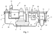
- a pump arrangement according to the invention according to Fig. 1 and 2 comprises as essential components a liquid container 1, an at least partially provided in the liquid container 1, electric motor driven pump 2 and a closure lid 3 for the liquid container 1.
- the liquid container 1 provides a container bottom 4 and a circumferential side wall 5, which integrally formed on the container bottom 4 and is integral with this.
- the closure lid 3 is provided for closing an opening of the liquid container 1.
- a circumferential seal 6 is provided to seal the closure lid 3 against the side wall 5 of the liquid container 1 is between the closure lid 3 and the side wall 5 a circumferential seal 6 is provided.
- the closure lid 3 and the liquid container 1 are fixed in an assembly position via a latching connection 7 positively against each other.
- a sump 8 is formed at the lowest point, in which liquid optionally mixed with solids collects.
- the sump 8 is a pump housing 9 and an unillustrated, provided in the pump housing 9 impeller of the pump 2 assigned.
- a connection section 10 is provided on the liquid container 1, to which an external, not shown supply line for the liquid can be connected. The connection section 10 is provided above the sump 8.
- a siphon-like conduit section 11 Adjacent to the connection section 10, in the liquid container 1, spatially integrated, a siphon-like conduit section 11 serving as an odor stop is provided.
- the line section 11 has three concentrically arranged, annular walls 12, 13, 14.
- An outer wall 12 is formed integrally with the container bottom 4 of the liquid container 1 and projects as the first riser wall 12 in the direction of the closure lid 3 from the container bottom 4.
- a free end face 15 of the first riser wall 12 faces the closure lid 3.
- the fall wall 13 is designed in one piece with the closure lid 3. It protrudes from the closure lid 3 in the direction of the container bottom 4.
- a free end face 16 of the fall wall 13 is facing the container bottom 4. With a free end 16 having free end, the fall wall 13 projects into the first riser wall 12 of the siphon-like line section eleventh
- the fall wall 13 in the region of a free end 16 having the free end thereof a second riser 14, which protrudes like the first riser 12 in the direction of the closure lid 3 from the container bottom 4 and is provided concentrically to the first riser wall 12.
- a free end face 17 of the second riser wall 14 in this case faces the closure lid 3.
- the free end face 17 of the second riser 14 is - based on the installation position - arranged at an equal height level as the free end face 15 of the first riser wall 12.
- the second riser wall 14 connects directly to the connection portion 10 of the liquid container 1 at.
- the second riser wall 14 is made in one piece with the container bottom 4 of the liquid container 1.
- the pump 2 has, in addition to the pump housing 9 and the impeller provided therein an electric motor, not shown, and a motor housing 18 accommodating the electric motor.
- the electric motor As part of the electric motor is in particular one in the Furthermore, the electric motor provides a stator and a rotatably held in relation to the stator on a shaft carrying the pump impeller rotor before.
- an inlet opening and a discharge nozzle 20 are provided on the pump housing 9 adjacent to the container bottom 4.
- a floating body 21 is realized, which is arranged to be height-adjustable or pivotable in the liquid container 1. In the floating body 21, a magnet 44 is inserted.
- the magnet 44 interacts with an active body, not shown, for example, a Hall sensor or reed switch, which is provided in a WirkMechaus originallyung 22, which is realized as part of the closure lid 3.
- an active body not shown, for example, a Hall sensor or reed switch, which is provided in a WirkMechaus originallyung 22, which is realized as part of the closure lid 3.
- two connecting pieces 23, 24 are formed on the closure lid 3, which serve to connect the pump arrangement with additional lines, for example condensate lines.
- the fluid which is optionally added with solids, is supplied to the liquid container 1 via the supply line, not shown, and the connection section 10.
- the liquid flows in this case in a flow direction 25 and, after passing through the connection section 10, enters the effective region of the siphon-like line section 11 arranged upstream of the feed line and the connection section 10 with respect to the flow direction 25 and designed as an odor trap.
- the flow direction 25 flows through optionally Solids staggered liquid thus first the supply line, not shown, and then passes into the arranged in relation to the flow direction 25 in front of the supply line connection section 10. Again in front of the connection section 10 is in the flow direction 25 considered the siphon-like formed line section 11, in which the liquid after flowing through of the connection section 10 passes.
- the walls 12, 13, 14 of the siphon-like line section 11 act like a labyrinth.
- the liquid exits via an opening 26 formed in the region of the free end face 17 of the second riser wall 14 and fills a liquid reservoir 27 of the line section 11 formed as an annular space, which is formed between the first riser wall 12 and the second riser wall 14.
- the fall wall 13 projects with the free end or the free end face 16 into it. Since the fall wall 13 is integrally formed with the closure lid 3, a gas-tight separation between the supply line, not shown, and a pump 2 receiving the pump 2 in some cases and the sump 8 having storage area 28 of the liquid container 1 is formed via the liquid reservoir 27.
- the liquid which is mixed with solids, for example crumbs, arrives from the cooking chamber via the supply line and the connection section 10 into the liquid container 1 provided upstream of the connection section 10 with respect to the flow direction 25 of the liquid.
- the discharge connection 20 and the discharge line not shown, the Liquid either supplied to the cooking chamber again or finally taken from the fluid circuit, that is carried away.
- a pump arrangement according to the invention may alternatively be provided in household appliances which carry water, for example in dishwashers or washing machines, in industrial water-conducting appliances or in sanitary facilities.
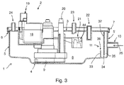
- a first wall 32 is realized as an integrally formed with the closure cover 3 case wall 32 which extends parallel to a connecting portion 10 of the pump assembly having side wall portion 5 '.
- a free peripheral edge 34 of the case wall 32 is hereby provided facing the container bottom 4.
- a second wall 33 is realized as a riser wall 33. The riser wall 33 protrudes from the container bottom 4 in the direction of the closure cap 3 of the pump arrangement.
- a free peripheral edge 36 of the riser wall 33 is provided with respect to the illustrated installation position of the pump assembly above the free peripheral edge 34 of the casement wall 32.
- the riser wall 33 is oriented parallel to the fall wall 32. While the riser wall 33 is preferably integrally connected to the side wall 5, gaskets, not shown, are provided between the fall wall 32 and the side wall 5 for realizing a gas-tight connection of the fall wall 32 with the side wall 5 of the liquid container 1.
- the labyrinthine arranged walls 32, 33 of the siphon-like line section 11 act insofar as odor stop.
- the siphon-like line section 11 designed as a smell stop is formed in the area of the container bottom 4.
- a substantially parallel to the container bottom 4 extending intermediate bottom 40 is provided.
- a circumferential web 41 is formed at the edge.
- the web 41 serves to receive a peripheral seal 42, which is provided in the illustrated assembly position between the side wall 5 and the web 41 of the intermediate bottom 40.
- the siphon-like, angled formed line section 11 is therefore gas-tight between the container bottom 4, the side wall 5 and the intermediate bottom 40 is formed.
- a passage opening 43 is provided for the optional solids mixed with liquid.
- the liquid passes into the sump 8 of the liquid container 1 formed above the intermediate bottom 40. If the pump 2 of the pump arrangement is operated and the liquid, optionally mixed with solids, is removed from the storage area 28 of the liquid container 1, residual liquid always remains in the deep space lying part of the siphon-like line section 11, which serves as a liquid reservoir.
- the partially filled with liquid line section 11 acts insofar as odor stop and prevents the passage of foul-smelling gases.
Landscapes
- Engineering & Computer Science (AREA)
- Mechanical Engineering (AREA)
- General Engineering & Computer Science (AREA)
- Structures Of Non-Positive Displacement Pumps (AREA)
Abstract
Description
- Die Erfindung betrifft eine Pumpenanordnung umfassend eine elektromotorisch antreibbare Pumpe zum Fördern einer optional Feststoffe aufweisenden Flüssigkeit mit einem an einer rotierenden Welle gehaltenen Pumpenrad und einen das Pumpenrad jedenfalls abschnittsweise umgreifenden Pumpengehäuse, an dem eine Zulauföffnung für die optional mit den Feststoffen versetzte Flüssigkeit und ein Ablaufstutzen für die optional mit den Feststoffen versetzte Flüssigkeit vorgesehen sind, einen zur Aufnahme der optional die Feststoffe aufweisenden Flüssigkeit ausgebildeten Flüssigkeitsbehälter mit einem Behälterboden, mit einer Seitenwand und mit einer dem Behälterboden gegenüberliegenden Öffnung, wobei an dem Flüssigkeitsbehälter ein Anschlussabschnitt für eine externe Zuleitung und ein zur Aufnahme des Pumpenrads und des Pumpengehäuses ausgebildeter Sumpf vorgesehen sind, und einen als Geruchsstopp dienenden, siphonartig ausgebildeten Leitungsabschnitt für die optional mit den Feststoffen versetzte Flüssigkeit.
- Gattungsgemäße Pumpenanordnungen werden heute in großer Stückzahl beispielsweise in Wasser führenden Haushaltsgeräten wie Waschmaschinen oder Geschirrspülern, in Gargeräten und im Bereich der Sanitärtechnik eingesetzt. Üblich ist hierbei, an dem Flüssigkeitsbehälter einen bezogen auf eine Einbaulage tief liegenden Sumpf vorzusehen, in dem sich die optional mit Feststoffen versetzte Flüssigkeit bevorzugt sammelt. Das Pumpenrad der Flüssigkeitspumpe sowie das das Pumpenrad umgreifende Pumpengehäuse sind in diesem Sumpf angeordnet. Die spezielle Anordnung stellt dabei sicher, dass die optional mit den Feststoffen versetzte Flüssigkeit möglichst vollständig aus dem Flüssigkeitsbehälter abgefördert werden kann. Um auch im Falle eines nahezu vollständig entleerten Flüssigkeitsbehälters einer nicht erwünschten Geruchsbildung vorzubeugen, wird heute üblicherweise im Bereich einer zu dem Flüssigkeitsbehälter geführten Zuleitung für die Flüssigkeit ein siphonartig ausgebildeter Leitungsabschnitt als Geruchsstopp vorgesehen. Die optional mit Feststoffen versetzte Flüssigkeit strömt insofern zunächst durch die Zuleitung und den siphonartigen Leitungsabschnitt und gelangt dann durch den Anschlussabschnitt in den Flüssigkeitsbehälter, welcher bezogen auf eine Fließrichtung der optional mit Feststoffen versetzten Flüssigkeit vor der Zuleitung und dem siphonartig ausgebildeten Leitungsabschnitt angeordnet ist. Der siphonartige Leitungsabschnitt ist beispielsweise U-förmig ausgebildet und so angeordnet, dass auch nach dem vollständigen Entleeren des Flüssigkeitsbehälters eine Restmenge an Flüssigkeit in dem U-förmigen Leitungsabschnitt verbleibt. Dieses Flüssigkeitsreservoir verschließt die Zuleitung gasdicht mit der Folge, dass ein Geruchsstopp gebildet und einer nicht akzeptablen, unerwünschten Geruchsbildung vorgebeugt ist.
- Grundsätzlich hat sich die gattungsgemäße Pumpenanordnung in der Praxis über viele Jahre bewährt. Gleichwohl besteht stets der Wunsch, die Kosten der Pumpenanordnung zu senken und den Bauraumbedarf zu reduzieren.
- Aufgabe der vorliegenden Erfindung ist es insofern, eine alternative konstruktive Ausführung für die Pumpenanordnung anzugeben, welche der Forderung nach Kostenreduzierung genügt und eine besonders kompakte Bauform aufweist.
- Zur Lösung der Aufgabe ist die Erfindung in Verbindung mit dem Oberbegriff des Patentanspruchs 1 dadurch gekennzeichnet, dass der siphonartige Leitungsabschnitt in eine Fließrichtung der optional mit den Feststoffen versetzten Flüssigkeit betrachtet vor dem Anschlussabschnitt des Flüssigkeitsbehälters vorgesehen ist.
- Der besondere Vorteil der Erfindung besteht darin, dass durch die Positionierung des siphonartigen Leitungsabschnitts vor dem Anschlussabschnitt der Montageaufwand zur Installation der Pumpenanordnung reduziert wird. Die externe Zuleitung muss nunmehr allein mit dem Anschlussabschnitt des Flüssigkeitsbehälters verbunden werden. Eine Integration des siphonartigen Leitungsabschnitts in die Zuleitung entfällt. Zudem reduziert sich der Aufwand bei der Kontrolle der Dichtigkeit, da nur noch eine und nicht wie heute üblich wenigstens zwei Verbindungsstellen zu prüfen sind.
- Im Rahmen der Erfindung gilt hierbei, dass die optional mit Feststoffen versetzte Flüssigkeit durch die Zuleitung in Richtung des Flüssigkeitsbehälters fließt. Sie kann hierbei aktiv durch die Zuleitung gefördert oder beispielsweise aufgrund der Einbausituation über ein in der Zuleitung realisiertes Gefälle beziehungsweise eine Höhendifferenz passiv durch die Zuleitung strömen. Die Zuleitung ist mit dem Anschlussabschnitt des Flüssigkeitsbehälters verbunden. Der Anschlussabschnitt liegt insofern in die Flussrichtung der Flüssigkeit betrachtet vor der Zuleitung. Über den Anschlussabschnitt gelangt die Flüssigkeit ins Innere des Flüssigkeitsbehälters. Im Sprachgebrauch der Erfindung gilt insofern, dass bezogen auf die Fließrichtung der Flüssigkeit der Flüssigkeitsbehälter und der siphonartige Leitungsabschnitt vor dem Anschlussabschnitt liegen. Aus dem Flüssigkeitsbehälter wird die optional mit Feststoffen versetzte Flüssigkeit dann über die elektromotorisch betriebene Pumpe abgepumpt. Beispielsweise wird sie einem Wirkkreislauf erneut zugeführt oder abgefördert.
- Bezogen auf die Fließrichtung durchströmt die optional mit Feststoffen versetzte Flüssigkeit also zunächst die nicht dargestellte Zuleitung und gelangt dann in den bezogen auf die Fließrichtung vor der Zuleitung angeordneten Anschlussabschnitt. Wiederum vor dem Anschlussabschnitt liegt in die Fließrichtung betrachtet der siphonartig gebildete Leitungsabschnitt, in den die Flüssigkeit nach dem Durchströmen des Anschlussabschnitts gelangt.
- Als siphonartig ausgebildeter Leitungsabschnitt im Sinne der Erfindung gilt jeder gebogen geformte beziehungsweise labyrinthartige Leitungsabschnitt, der aufgrund seiner Geometrie bei einer geeigneten Einbaulage ein Flüssigkeitsreservoir definiert, welches bei der Aufnahme einer ausreichenden Menge von Flüssigkeit den Durchtritt von Gasen verhindert und so als Geruchsverschluss dient. Häufig verwendet sind hierbei insbesondere der Röhrensiphon, welcher häufig U-förmig gebildet ist, und der Flaschen- beziehungsweise Taschensiphon.
- Nach einer bevorzugten Ausführungsform der Erfindung ist der als Geruchsverschluss ausgebildete siphonartige Leitungsabschnitt räumlich in dem Flüssigkeitsbehälter integriert. Vorteilhaft ergibt sich hierbei zusätzlich zu der verbesserten Montagefähigkeit eine besonders kompakte Bauform der erfindungsgemäßen Pumpenanordnung, die die Integration der Pumpenanordnung in bestehende und neu entwickelte Geräte (Waschmaschinen, Geschirrspüler, Gargerät, ...) vereinfacht. Insbesondere kann der Flüssigkeitsbehälter mit dem räumlich integrierten siphonartigen Leitungsabschnitt geometrisch an den Bauraum angepasst werden, den das zur Aufnahme der Pumpenanordnung vorgesehene Gerät zur Verfügung stellt. Der Bauraumbedarf für die Zuleitung kann durch den Verzicht auf das Vorsehen des externen Siphons signifikant reduziert werden.
- Nach einer Weiterbildung der Erfindung ist in einer Zusammenbaustellung der Pumpenanordnung ein an die Seitenwand des Flüssigkeitsbehälters angelegter Verschlussdeckel zum Verschließen der Öffnung des Flüssigkeitsbehälters vorgesehen. Bevorzugt ist zwischen dem Verschlussdeckel und der Seitenwand eine umlaufende Dichtung angeordnet. Vorteilhaft dienen der Verschlussdeckel und insbesondere auch die umlaufende Dichtung als weiterer Geruchsverschluss. Es wird insofern ein dichter Flüssigkeitsbehälter für die optional mit Feststoffen versetzte Flüssigkeit bereitgestellt.
- Nach einer Weiterbildung der Erfindung sind als Teil des siphonartigen Leitungsabschnitts labyrinthartig angeordnete Wandungen vorgesehen, welche sich zwischen der Seitenwand des Flüssigkeitsbehälters erstrecken. Insbesondere sind die Seitenwand des Flüssigkeitsbehälters und wenigstens einzelne der labyrinthartig angeordneten Wandungen des siphonartigen Leitungsabschnitts einstückig ausgebildet. Vorteilhaft begünstigt die spezielle Anordnung der Wandungen die kompakte Bauform. Durch die einstückige Realisierung reduziert sich die Anzahl der Bauteile und der Montageaufwand sinkt. Es ist überdies einer Fehlmontage vorgebeugt und einem Ausfall der Geruchsstopp-Funktion, etwa durch das Lösen einer Verbindung oder eine Undichtigkeit der Dichtung, entgegengewirkt.
- Nach einer Weiterbildung der Erfindung sind als Teil des siphonartigen Leitungsabschnitts eine von dem Behälterboden in Richtung der Öffnung erstreckte erste Steigwandung und eine von dem Verschlussdeckel in Richtung des Behälterbodens erstreckte Fallwandung vorgesehen. Beispielsweise ist die Steigwandung einstückig mit dem Behälterboden realisiert. Beispielsweise ist zwischen der ersten Steigwandung und dem Behälterboden eine Dichtung vorgesehen. Ebenso können die Fallwandung und der Verschlussdeckel einstückig realisiert sein oder es ist eine Dichtung zwischen der Fallwandung und dem Verschlussdeckel vorgesehen zur Realisierung der gasdichten Anbindung der Fallwandung an den Verschlussdeckel. Eine gasdichte Anbindung der Fallwandung an der Seitenwand wird beispielsweise durch eine Dichtung realisiert. Vorteilhaft ergibt sich eine sehr kompakte Bauform vor dem siphonartigen Leitungsabschnitt. Darüber hinaus ergibt sich insbesondere bei der einstückigen Realisierung eine fertigungsgerechte Konstruktion, wenn die erste Steigwandung von dem Behälterboden oder die Fallwandung von dem Verschlussdeckel in Richtung einer Öffnung eines Spritzgießwerkzeugs senkrecht beziehungsweise ohne Hinterschnitt abragt und der Flüssigkeitsbehälter oder der Verschlussdeckel als Spritzgießteil, bevorzugt als Kunststoffspritzgießteil realisiert werden.
- Nach einer Weiterbildung der Erfindung sind die erste Steigwandung und die Fallwandung ringförmig ausgebildet und/oder einander konzentrisch zugeordnet. Insbesondere kann die Zuordnung so vorgesehen sein, dass die erste Steigwandung mit einem dem Verschlussdeckel zugewandten freien Ende ein dem Behälterboden zugewandtes freies Ende der Fallwandung mantelseitig umgreift. Es definiert beziehungsweise begrenzt hierbei die erste Steigwandung das von dem siphonartigen Leitungsabschnitt gebildete Flüssigkeitsreservoir, in das die Fallwandung mit den freien Enden hineinragt.
- Optional kann eine zweite Steigwandung vorgesehen werden. Diese zweite Steigwandung kann ebenfalls ringförmig ausgebildet beziehungsweise konzentrisch zu der ersten Steigwandung und/oder der Fallwandung vorgesehen werden. Insbesondere kann die zweite Steigwandung sich unmittelbar an den Anschlussabschnitt des Flüssigkeitsbehälters anschließen. Die wenigstens eine Steigwandung und die Fallwandung definieren durch ihre labyrinthartige Zuordnung den siphonartigen Leitungsabschnitt. Ihre spezielle Geometrie und Anordnung erlauben es, den Leitungsabschnitt ohne Hinterschnitte und gebogene Leitungspassagen so auszuführen, dass eine kostengünstige Massenfertigung und eine einstückige Realisierung des Flüssigkeitsbehälters einerseits und des Verschlussdeckels andererseits begünstigt werden, wobei an dem Flüssigkeitsbehälter und an dem Verschlussdeckel jeweils ein Teil der Wandungen angeformt ist.
- Jeweils können die Fallwandung und die Steigwandungen ringförmig ausgebildet sein beziehungsweise einen unterschiedlichen Durchmesser beziehungsweise Querschnitt aufweisen. Die Wandungen können kaskadenartig so ineinander gestülpt sein, dass stets eine nächstgrößere Wandung eine kleinere Wandung umgreift. Die Fallwandung kann insbesondere zwischen der ersten Steigwandung und der zweiten Steigwandung vorgesehen werden.
- Nach einer alternativen Ausführungsform der Erfindung kann der siphonartige Leitungsabschnitt zwischen dem Behälterboden einerseits und einem beabstandet zu dem Behälterboden vorgesehenen Zwischenboden gebildet sein. An dem Zwischenboden ist bevorzugt ein umlaufender Steg vorgesehen, wobei eine ebenfalls umlaufende Dichtung zwischen dem Steg des Zwischenbodens und der Seitenwandung vorgesehen ist. Die umlaufende Dichtung dient insbesondere dazu, den siphonartigen Leitungsabschnitt gasdicht als Geruchsverschluss auszubilden. Vorteilhaft ergibt sich durch das Vorsehen des siphonartigen Leitungsabschnitts zwischen dem Behälterboden und dem Zwischenboden eine sehr kompakte Bauform, welche Vorteile bieten kann in Bezug auf die räumliche Integration der Pumpenanordnung in das übergeordnete Gerät.
- Aus den weiteren Unteransprüchen und der nachfolgenden Beschreibung sind weitere Vorteile, Merkmale und Einzelheiten der Erfindung zu entnehmen. Dort erwähnte Merkmale können jeweils einzeln für sich oder auch in beliebiger Kombination erfindungswesentlich sein. Die Zeichnungen dienen lediglich beispielhaft der Klarstellung der Erfindung und haben keinen einschränkenden Charakter.
- Figur 1
- einen Längsschnitt durch eine erste Ausführungsform einer erfindungsgemäßen Pumpenanordnung,
- Figur 2
- einen Querschnitt durch die Pumpenanordnung nach
Fig. 1 , - Figur 3
- einen Längsschnitt durch eine zweite Ausführungsform einer erfindungsgemäßen Pumpenanordnung,
- Figur 4
- einen Längsschnitt durch eine dritte Ausführungsform einer erfindungsgemäßen Pumpenanordnung und
- Figur 5
- einen Querschnitt durch die Pumpenanordnung nach
Figur 4 . - Eine erfindungsgemäße Pumpenanordnung nach den
Fig. 1 und2 umfasst als wesentliche Komponenten einen Flüssigkeitsbehälter 1, eine jedenfalls abschnittsweise in dem Flüssigkeitsbehälter 1 vorgesehene, elektromotorisch angetriebene Pumpe 2 sowie einen Verschlussdeckel 3 für den Flüssigkeitsbehälter 1. Der Flüssigkeitsbehälter 1 sieht einen Behälterboden 4 sowie eine umlaufende Seitenwand 5 vor, welche an dem Behälterboden 4 angeformt und einstückig mit diesem ausgeführt ist. Dem Behälterboden 4 gegenüberliegend ist der Verschlussdeckel 3 vorgesehen zum Verschließen einer Öffnung des Flüssigkeitsbehälters 1. Um den Verschlussdeckel 3 gegen die Seitenwand 5 des Flüssigkeitsbehälters 1 zu dichten, ist zwischen dem Verschlussdeckel 3 und der Seitenwand 5 eine umlaufende Dichtung 6 vorgesehen. Der Verschlussdeckel 3 und der Flüssigkeitsbehälter 1 sind in einer Zusammenbaustellung über eine Rastverbindung 7 formschlüssig gegeneinander festgelegt. - An dem Flüssigkeitsbehälter 1 ist im Bereich des Behälterbodens 4 in der gezeigten Orientierung (Einbaulage) der Pumpenanordnung an der tiefsten Stelle ein Sumpf 8 ausgebildet, in dem sich optional mit Feststoffen versetzte Flüssigkeit sammelt. Dem Sumpf 8 sind ein Pumpengehäuse 9 und ein nicht dargestelltes, in dem Pumpengehäuse 9 vorgesehenes Pumpenrad der Pumpe 2 zugeordnet. Ferner ist an dem Flüssigkeitsbehälter 1 ein Anschlussabschnitt 10 vorgesehen, an dem eine externe, nicht dargestellte Zuleitung für die Flüssigkeit angeschlossen werden kann. Der Anschlussabschnitt 10 ist dabei oberhalb des Sumpfes 8 vorgesehen.
- Benachbart zu dem Anschlussabschnitt 10 ist in dem Flüssigkeitsbehälter 1 räumlich integriert ein als Geruchsstopp dienender, siphonartig ausgebildeter Leitungsabschnitt 11 vorgesehen. Der Leitungsabschnitt 11 weist drei zueinander konzentrisch angeordnete, ringförmige Wandungen 12, 13, 14 auf. Eine äußere Wandung 12 ist einstückig mit dem Behälterboden 4 des Flüssigkeitsbehälters 1 ausgebildet und ragt als erste Steigwandung 12 in Richtung des Verschlussdeckels 3 von dem Behälterboden 4 ab. Eine freie Stirnseite 15 der ersten Steigwandung 12 ist dabei dem Verschlussdeckel 3 zugewandt. Die Fallwandung 13 ist einstückig mit dem Verschlussdeckel 3 ausgeführt. Sie ragt von dem Verschlussdeckel 3 in Richtung des Behälterbodens 4 ab. Eine freie Stirnseite 16 der Fallwandung 13 ist dabei dem Behälterboden 4 zugewandt. Mit einem die freie Stirnseite 16 aufweisenden freien Ende ragt die Fallwandung 13 in die erste Steigwandung 12 des siphonartig ausgebildeten Leitungsabschnitts 11.
- Mantelseitig umfasst die Fallwandung 13 im Bereich eines die freie Stirnseite 16 aufweisenden freien Endes derselben eine zweite Steigwandung 14, welche wie die erste Steigwandung 12 in Richtung des Verschlussdeckels 3 von dem Behälterboden 4 abragt und konzentrisch zu der ersten Steigwandung 12 vorgesehen ist. Eine freie Stirnseite 17 der zweiten Steigwandung 14 ist hierbei dem Verschlussdeckel 3 zugewandt. Die freie Stirnseite 17 der zweiten Steigwandung 14 ist - bezogen auf die Einbaulage - auf einem gleichen Höhenniveau angeordnet wie die freie Stirnseite 15 der ersten Steigwandung 12. Die zweite Steigwandung 14 schließt sich unmittelbar an den Anschlussabschnitt 10 des Flüssigkeitsbehälters 1 an. Wie die erste Steigwandung 12 ist auch die zweite Steigwandung 14 einstückig mit dem Behälterboden 4 des Flüssigkeitsbehälters 1 ausgeführt.
- Die Pumpe 2 weist neben dem Pumpengehäuse 9 und dem darin vorgesehenen Pumpenrad einen nicht dargestellten Elektromotor und ein den Elektromotor aufnehmendes Motorengehäuse 18 auf. Als Teil des Elektromotors ist insbesondere eine in dem Motorengehäuse 18 angeordnete Ansteuerung vorgesehen sowie ein aus dem Motorengehäuse herausgeführter Anschlusskontakt 19. Des Weiteren sieht der Elektromotor einen Stator und einen drehbar in Bezug zu dem Stator an einer das Pumpenrad tragenden Welle gehaltenen Rotor vor. An dem Pumpengehäuse 9 sind benachbart zu dem Behälterboden 4 eine Zulauföffnung sowie ein Ablaufstutzen 20 vorgesehen. Ferner ist als Teil der Pumpenanordnung ein Schwimmkörper 21 realisiert, welcher höhenverstellbar beziehungsweise schwenkbar in dem Flüssigkeitsbehälter 1 angeordnet ist. In den Schwimmkörper 21 ist ein Magnet 44 eingelassen. Der Magnet 44 interagiert mit einem nicht dargestellten Wirkkörper, beispielsweise einem Hallsensor oder Reedschalter, welcher in einer Wirkkörperausnehmung 22 vorgesehen ist, die als Teil des Verschlussdeckels 3 realisiert ist. Zusätzlich sind an dem Verschlussdeckel 3 zwei Anschlussstutzen 23, 24 angeformt, welche der Verbindung der Pumpenanordnung mit zusätzlichen Leitungen, beispielsweise Kondensatleitungen, dienen.
- Während des Betriebs der Pumpenanordnung wird dem Flüssigkeitsbehälter 1 die optional mit Feststoffen versetzte Flüssigkeit über die nicht dargestellte Zuleitung und den Anschlussabschnitt 10 zugeführt. Die Flüssigkeit strömt hierbei in eine Fließrichtung 25 und gelangt nach Durchtritt durch den Anschlussabschnitt 10 in den Wirkbereich des bezogen auf die Fließrichtung 25 vor der Zuleitung und dem Anschlussabschnitt 10 angeordneten und als Geruchsverschluss ausgebildeten siphonartigen Leitungsabschnitts 11. Bezogen auf die Fließrichtung 25 durchströmt die optional mit Feststoffen versetzte Flüssigkeit also zunächst die nicht dargestellte Zuleitung und gelangt dann in den bezogen auf die Fließrichtung 25 vor der Zuleitung angeordneten Anschlussabschnitt 10. Wiederum vor dem Anschlussabschnitt 10 liegt in die Fließrichtung 25 betrachtet der siphonartig gebildete Leitungsabschnitt 11, in den die Flüssigkeit nach dem Durchströmen des Anschlussabschnitts 10 gelangt. Die Wandungen 12, 13, 14 des siphonartigen Leitungsabschnitts 11 wirken hierbei labyrinthartig zusammen. Die Flüssigkeit tritt über eine im Bereich der freien Stirnseite 17 der zweiten Steigwandung 14 gebildete Öffnung 26 aus und füllt ein als Ringraum ausgebildetes Flüssigkeitsreservoir 27 des Leitungsabschnitts 11, welches zwischen der ersten Steigwandung 12 und der zweiten Steigwandung 14 gebildet ist. In den mit der Flüssigkeit gefüllten Ringraum 27 ragt die Fallwandung 13 mit dem freien Ende beziehungsweise der freien Stirnseite 16 hinein. Da die Fallwandung 13 stoffschlüssig mit dem Verschlussdeckel 3 ausgebildet ist, ist über das Flüssigkeitsreservoir 27 eine gasdichte Trennung zwischen der nicht dargestellten Zuleitung und einem die Pumpe 2 jedenfalls abschnittsweise aufnehmenden und dem Sumpf 8 aufweisenden Vorratsbereich 28 des Flüssigkeitsbehälters 1 gebildet.
- Wenn der Ringraum 27 vollständig gefüllt ist, fließt die Flüssigkeit über eine durch die freie Stirnseite 15 und den Mantel der Fallwandung 13 definierte Ringöffnung 29 in den Vorratsbereich 28 des Flüssigkeitsbehälters 1. Die Flüssigkeit sammelt sich zunächst am tiefsten Punkt, das heißt im Bereich des Sumpfs 8 des Flüssigkeitsbehälters 1. Abhängig vom Füllstand des Flüssigkeitsbehälters 1 definiert sich die Position des Schwimmkörpers 21. Sobald der Schwimmkörper 21 eine definierte Relativposition zu dem in der Wirkkörperausnehmung 22 vorgesehenen Wirkkörper einnimmt, wird ein Steuersignal für die Pumpe 2 erzeugt. Die Pumpe 2 läuft an und die Flüssigkeit, welche über die Zulauföffnung des Pumpengehäuses 9 in ebendieses eintritt, wird über den Ablaufstutzen 20 und eine nicht dargestellte Ablaufleitung abgepumpt.
- Gezeigt ist exemplarisch eine erfindungsgemäße Pumpenanordnung für Gargeräte. Vorliegend gelangt die mit Feststoffen, beispielsweise Bratresten versetzte Flüssigkeit aus dem Garraum über die nicht dargestellte Zuleitung und den Anschlussabschnitt 10 in den bezogen auf die Fließrichtung 25 der Flüssigkeit vor dem Anschlussabschnitt 10 vorgesehenen Flüssigkeitsbehälter 1. Über den Ablaufstutzen 20 und die nicht dargestellte Ablaufleitung wird die Flüssigkeit entweder dem Garraum erneut zugeführt oder dem Fluidkreislauf endgültig entnommen, das heißt abgefördert.
- Eine erfindungsgemäße Pumpenanordnung kann alternativ vorgesehen werden in Wasser führenden Haushaltsgeräten, beispielsweise in Geschirrspülmaschinen oder Waschmaschinen, in gewerblichen Wasser führenden Geräten oder im Sanitäranlagenbau.
- Während nach dem ersten Ausführungsbeispiel der Erfindung gemäß den
Fig. 1 und2 der siphonartig ausgebildete Leitungsabschnitt 11 der Pumpenanordnung durch die drei einander konzentrisch zugeordnete, labyrinthartig zusammenwirkende Wandungen 12, 13, 14 gebildet ist, sieht eine zweite Ausführungsform einer erfindungsgemäßen Pumpenanordnung nach derFig. 3 zwei scheibenartige Wandungen 32, 33 vor. Eine erste Wandung 32 ist dabei als eine einstückig mit dem Verschlussdeckel 3 ausgebildete Fallwandung 32 realisiert, welche sich parallel zu einem den Anschlussabschnitt 10 der Pumpenanordnung aufweisenden Seitenwandabschnitt 5' erstreckt. Eine freie Randkante 34 der Fallwandung 32 ist hierbei dem Behälterboden 4 zugewandt vorgesehen. Eine zweite Wandung 33 ist als Steigwandung 33 realisiert. Die Steigwandung 33 ragt von dem Behälterboden 4 in Richtung des Verschlussdeckels 3 der Pumpenanordnung ab. Eine freie Randkante 36 der Steigwandung 33 ist bezogen auf die dargestellte Einbaulage der Pumpenanordnung oberhalb der freien Randkante 34 der Fallwandung 32 vorgesehen. Die Steigwandung 33 ist parallel zur Fallwandung 32 orientiert. Während die Steigwandung 33 bevorzugt einstückig mit der Seitenwand 5 verbunden ist, sind zwischen der Fallwandung 32 und der Seitenwand 5 nicht dargestellte Dichtungen vorgesehen zur Realisierung einer gasdichten Verbindung der Fallwandung 32 mit der Seitenwand 5 des Flüssigkeitsbehälters 1. - Gleiche Bauteile und Bauteilfunktionen sind durch gleiche Bezugszeichen gekennzeichnet.
- Ein zwischen der Steigwandung 33 und dem den Anschlussabschnitt 10 aufweisenden Seitenwandabschnitt 5' gebildetes Flüssigkeitsreservoir 35 des in die Fließrichtung 25 der optional mit Feststoffen versetzte Flüssigkeit betrachtet vor dem Anschlussabschnitt 10 angeordneten, siphonartig ausgebildeten Leitungsabschnitts 11 wird beim Zufluss von Flüssigkeit über die nicht dargestellte Zuleitung und den bezogen auf die Fließrichtung 25 der Flüssigkeit vor der Zuleitung gelegenen Anschlussabschnitt 10 zunächst gefüllt. Da die Fallwandung 32 bis in den Bereich des Flüssigkeitsreservoirs 35 hineinragt, ist wie gehabt eine gasdichte Trennung der nicht dargestellten Zuleitung von dem Vorratsbereich 28 des Flüssigkeitsbehälters 1 realisiert. Die labyrinthartig angeordneten Wandungen 32, 33 des siphonartigen Leitungsabschnitts 11 wirken insofern als Geruchsstopp. Zugleich ist durch das horizontale Höhenniveau der freien Randkante 36 der Steigwandung 33 relativ zum Sumpf 8 des Flüssigkeitsbehälters 1 sichergestellt, dass das Flüssigkeitsreservoir 35 auch dann von der optional mit Feststoffen versetzten Flüssigkeit gefüllt ist, wenn die Flüssigkeit aus dem Vorratsbereich 28 vollständig oder nahezu vollständig abgefördert ist.
- Nach einer dritten alternativen Ausführungsform der erfindungsgemäßen Pumpenanordnung gemäß der
Fig. 4 und5 ist der als Geruchsstopp ausgebildete siphonartige Leitungsabschnitt 11 im Bereich des Behälterbodens 4 gebildet. Hierbei ist ein sich im Wesentlichen parallel zum Behälterboden 4 erstreckender Zwischenboden 40 vorgesehen. An dem Zwischenboden 40 ist randseitig ein umlaufender Steg 41 ausgebildet. Der Steg 41 dient zur Aufnahme einer umlaufenden Dichtung 42, welche in der dargestellten Zusammenbaustellung zwischen der Seitenwand 5 und dem Steg 41 des Zwischenbodens 40 vorgesehen ist. Der siphonartige, abgewinkelt ausgebildete Leitungsabschnitt 11 ist demzufolge gasdicht zwischen dem Behälterboden 4, der Seitenwand 5 und dem Zwischenboden 40 gebildet. In dem Zwischenboden 40 ist eine Durchtrittsöffnung 43 für die optional mit Feststoffen versetzte Flüssigkeit vorgesehen. Über die Durchtrittsöffnung 43 gelangt die Flüssigkeit in den oberhalb des Zwischenbodens 40 gebildeten Sumpf 8 des Flüssigkeitsbehälters 1. Wird die Pumpe 2 der Pumpenanordnung betrieben und die optional mit Feststoffen versetzte Flüssigkeit aus dem Vorratsbereich 28 des Flüssigkeitsbehälters 1 abgefördert, so verbleibt stets Restflüssigkeit in dem tief liegenden Teil des siphonartigen Leitungsabschnitts 11, der als Flüssigkeitsreservoir dient. Der teilweise mit Flüssigkeit befüllte Leitungsabschnitt 11 wirkt insofern als Geruchsstopp und verhindert den Durchtritt von übel riechenden Gasen.
Claims (13)
- Pumpenanordnung umfassend- eine elektromotorisch antreibbare Pumpe (2) zum Fördern einer optional Feststoffe aufweisenden Flüssigkeit mit einem an einer rotierenden Welle gehaltenen Pumpenrad und einen das Pumpenrad jedenfalls abschnittsweise umgreifenden Pumpengehäuse (9), an dem eine Zulauföffnung für die optional mit den Feststoffen versetzte Flüssigkeit und ein Ablaufstutzen (20) für die optional mit den Feststoffen versetzte Flüssigkeit vorgesehen ist.- einen zur Aufnahme der optional die Feststoffe aufweisenden Flüssigkeit ausgebildeten Flüssigkeitsbehälter(1) mit einem Behälterboden (4), mit einer Seitenwand (5) und mit einer dem Behälterboden (4) gegenüberliegenden Öffnung, wobei an dem Flüssigkeitsbehälter (1) ein Anschlussabschnitt (10) für eine externe Zuleitung und ein zur Aufnahme des Pumpenrads und des Pumpengehäuses (9) ausgebildeter Sumpf (8) vorgesehen sind, und- einen als Geruchsstopp dienenden, siphonartig ausgebildeten Leitungsabschnitt (11) für die optional mit den Feststoffen versetzte Flüssigkeit,dadurch gekennzeichnet, dass der siphonartige Leitungsabschnitt (11) in eine Fließrichtung (25) der optional mit den Feststoffen versetzten Flüssigkeit betrachtet vor dem Anschlussabschnitt (10) des Flüssigkeitsbehälters (1) vorgesehen ist.
- Pumpenanordnung nach Anspruch 1, dadurch gekennzeichnet, dass der als Geruchsstopp ausgebildete siphonartige Leitungsabschnitt (11) räumlich in dem Flüssigkeitsbehälter (1) integriert vorgesehen ist.
- Pumpenanordnung nach Anspruch 1 oder 2, dadurch gekennzeichnet, dass ein an die Seitenwand (5) des Flüssigkeitsbehälters (1) anlegbarer Verschlussdeckel (3) zum Verschließen der Öffnung vorgesehen ist, wobei bevorzugt zwischen dem Verschlussdeckel (3) und der Seitenwand (5) eine umlaufende Dichtung (6) vorgesehen ist.
- Pumpenanordnung nach einem der Ansprüche 1 bis 3, dadurch gekennzeichnet, dass der siphonartige Leitungsabschnitt (11) eine Mehrzahl von einander labyrinthartig zugeordneten Wandungen (12, 13, 14, 32, 33) vorsieht, welche sich zwischen der Seitenwand 5 des Flüssigkeitsbehälters (1) erstrecken.
- Pumpenanordnung nach einem der Ansprüche 1 bis 4, dadurch gekennzeichnet, dass als Teil des siphonartigen Leitungsabschnitts (11) eine von dem Behälterboden (4) in Richtung der Öffnung erstreckte erste Steigwandung (12, 33) vorgesehen ist und/oder dass als Teil des siphonartigen Leitungsabschnitts (11) eine von dem Verschlussdeckel (3) in Richtung des Behälterbodens (4) erstreckte Fallwandung (13, 32) vorgesehen ist.
- Pumpenanordnung nach einem der Ansprüche 1 bis 5, dadurch gekennzeichnet, dass die Steigwandung (12, 14, 33) von dem Behälterboden (4) abragt und/oder einstückig mit dem Behälterboden (4) und/oder der Seitenwand (5) des Flüssigkeitsbehälters (1) ausgeführt ist und/oder dass die Fallwandung (13, 32) von dem Verschlussdeckel (3) abragt und/oder einstückig mit dem Verschlussdeckel (3) ausgeführt ist.
- Pumpenanordnung nach einem der Ansprüche 1 bis 6, dadurch gekennzeichnet, dass die erste Steigwandung (12) und/oder die Fallwandung (13) des siphonartigen Leitungsabschnitts (11) ringförmig ausgebildet sind und/oder einander bevorzugt konzentrisch umgreifen.
- Pumpenanordnung nach Anspruch 7, dadurch gekennzeichnet, dass die erste Steigwandung (12) mit einem dem Verschlussdeckel (3) zugewandten freien Ende ein dem Behälterboden (4) zugewandtes freies Ende der Fallwandung mantelseitig (13) umgreift.
- Pumpenanordnung nach einem der Ansprüche 1 bis 8, dadurch gekennzeichnet, dass in einer Zusammenbaustellung eine dem Verschlussdeckel (3) zugewandte freie Stirnseite (15) der ersten Steigwandung (12) beabstandet zu dem Verschlussdeckel (3) und/oder eine dem Behälterboden (4) zugewandte zweite freie Stirnseite (16) der Fallwandung (13) beabstandet zu dem Behälterboden (4) vorgesehen ist.
- Pumpenanordnung nach einem der Ansprüche 1 bis 9, dadurch gekennzeichnet, dass eine von dem Behälterboden (4) in Richtung der Öffnung abragende zweite Steigwandung (14) des siphonartigen Leitungsabschnitts (11) vorgesehen ist, welche bevorzugt konzentrisch zu der ersten Steigwandung (12) und/oder der Fallwandung (13) angeordnet ist und/oder mit einer dem Verschlussdeckel (3) zugewandten freien Ende in das freie Ende der Fallwandung (13) des siphonartigen Leitungsabschnitts (11) hineinragt, und/oder dass das freie Ende der ersten Steigwandung (12) und das freie Ende der zweiten Steigwandung (14) auf einem gleichen horizontalen Höhenniveau vorgesehen sind.
- Pumpenanordnung nach dem Anspruch 10, dadurch gekennzeichnet, dass die Wandungen (12, 13, 14) kaskadenartig ineinander gestülpt vorgesehen sind und/oder einen unterschiedlichen Durchmesser oder einen unterschiedlichen Querschnitt aufweisen.
- Pumpenanordnung nach einem der Ansprüche 1 bis 11, dadurch gekennzeichnet, dass der siphonartige Leitungsabschnitt (11) zwischen dem Behälterboden (4) und einem beabstandet zu dem Behälterboden (4) vorgesehenen Zwischenboden (40) gebildet ist, wobei der Zwischenboden (40) einen umlaufenden Steg (41) vorsieht und wobei eine umlaufende Dichtung (42) zwischen dem Steg (41) des Zwischenbodens (40) und der Seitenwand (5) vorgesehen ist.
- Pumpenanordnung nach einem der Ansprüche 1 bis 12, dadurch gekennzeichnet, dass der siphonartige Leitungsabschnitt (11) in dem Flüssigkeitsbehälter (1) derart integriert vorgesehen ist, dass die über den Anschlussabschnitt (10) zugeführte, mit Feststoffen versetzte Flüssigkeit zunächst durch den siphonartigen Leitungsabschnitt (11) mit einem als Teil des siphonartigen Leitungsabschnitts (11) gebildeten Flüssigkeitsreservoir (27, 35) strömt und nach dem Verlassen des siphonartigen Leitungsabschnitts (11) mittels der elektrisch antreibbaren Pumpe (2) aus dem Flüssigkeitsbehälter (1) abförderbar ist.
Applications Claiming Priority (1)
| Application Number | Priority Date | Filing Date | Title |
|---|---|---|---|
| DE102015108977.7A DE102015108977B4 (de) | 2015-06-08 | 2015-06-08 | Pumpenanordnung |
Publications (2)
| Publication Number | Publication Date |
|---|---|
| EP3104016A1 true EP3104016A1 (de) | 2016-12-14 |
| EP3104016B1 EP3104016B1 (de) | 2020-09-09 |
Family
ID=56112804
Family Applications (1)
| Application Number | Title | Priority Date | Filing Date |
|---|---|---|---|
| EP16020220.6A Active EP3104016B1 (de) | 2015-06-08 | 2016-06-07 | Pumpenanordnung |
Country Status (2)
| Country | Link |
|---|---|
| EP (1) | EP3104016B1 (de) |
| DE (1) | DE102015108977B4 (de) |
Citations (4)
| Publication number | Priority date | Publication date | Assignee | Title |
|---|---|---|---|---|
| JP2000051134A (ja) * | 1998-08-17 | 2000-02-22 | Mitsubishi Electric Corp | 組込み形食器洗浄機 |
| US20080011335A1 (en) * | 2006-07-12 | 2008-01-17 | Samsung Electronics Co. Ltd. | Dish washing machine |
| EP1930493A1 (de) * | 2006-12-04 | 2008-06-11 | Bonferraro S.p.A. | Waschmaschine mit integriertem Waschbecken |
| EP1944420A1 (de) * | 2007-01-15 | 2008-07-16 | Kessel GmbH | Hebeanlage |
Family Cites Families (1)
| Publication number | Priority date | Publication date | Assignee | Title |
|---|---|---|---|---|
| US5868011A (en) * | 1997-04-04 | 1999-02-09 | General Electric Company | Water traps for washing machines |
-
2015
- 2015-06-08 DE DE102015108977.7A patent/DE102015108977B4/de active Active
-
2016
- 2016-06-07 EP EP16020220.6A patent/EP3104016B1/de active Active
Patent Citations (4)
| Publication number | Priority date | Publication date | Assignee | Title |
|---|---|---|---|---|
| JP2000051134A (ja) * | 1998-08-17 | 2000-02-22 | Mitsubishi Electric Corp | 組込み形食器洗浄機 |
| US20080011335A1 (en) * | 2006-07-12 | 2008-01-17 | Samsung Electronics Co. Ltd. | Dish washing machine |
| EP1930493A1 (de) * | 2006-12-04 | 2008-06-11 | Bonferraro S.p.A. | Waschmaschine mit integriertem Waschbecken |
| EP1944420A1 (de) * | 2007-01-15 | 2008-07-16 | Kessel GmbH | Hebeanlage |
Also Published As
| Publication number | Publication date |
|---|---|
| DE102015108977A1 (de) | 2016-12-08 |
| DE102015108977B4 (de) | 2021-10-21 |
| EP3104016B1 (de) | 2020-09-09 |
Similar Documents
| Publication | Publication Date | Title |
|---|---|---|
| EP1209275B1 (de) | Laugenabpumpstrang in einer Waschmaschine | |
| CH707892B1 (de) | Wäschetrockner mit Abwasserpumpe. | |
| DE1203484B (de) | Auf Fluessigkeitsstand in einem Behaelter ansprechende Einrichtung | |
| EP3733040A1 (de) | Wasserführendes haushaltsgerät | |
| EP3104016A1 (de) | Pumpenanordnung | |
| EP1775395B1 (de) | Ablaufarmatur für sanitäre Anlagen | |
| DE102008016476A1 (de) | Hausgerät mit einer Pumpe zur Förderung eines Mediums | |
| EP2041356B1 (de) | Laugenabpumpstrang | |
| DE102015220125B4 (de) | Tankeinfüllstutzen | |
| DE102004061306A1 (de) | Waschmittel-Einspüleinrichtung | |
| WO2014138761A1 (de) | Ablaufelement für eine duschwanne | |
| DE102018210207B4 (de) | Wasserführendes Haushaltsgerät mit einer Impellerpumpe | |
| DE8130642U1 (de) | Dosierventil, insbesondere zur abgabe viskoser fluessigkeiten | |
| DE102010037720B4 (de) | Sicherheitsvorrichtung für ein wassergespeistes Haushaltsgerät | |
| EP1574629A1 (de) | Ablaufarmatur für eine sanitäre Apparatur, insbesondere Duschwanne | |
| EP2024549B1 (de) | Waschmaschine mit notentleerungsschlauch | |
| DE10161300A1 (de) | Wäschebehandlungsmaschine in Form einer Waschmaschine oder eines Wäschetrockners | |
| EP2898812B1 (de) | Wasserführender Reinigungsautomat, insbesondere programmgesteuerter Geschirrspülautomat | |
| DE19932859C2 (de) | Aseptisches Pumpengehäuse mit schaltbarer Drainage | |
| WO2021048360A1 (de) | Abflusssystem und ein verfahren zum ableiten von flüssigkeiten | |
| DE8527754U1 (de) | Vorrichtung zum Schutz gegen Wasserschäden bei wasserführenden Hausgeräten | |
| DE202018105817U1 (de) | Absaugvorrichtung für Abwasserbehälter | |
| EP1288501A2 (de) | Drucksensor für eine Tauchpumpe | |
| DE102017105536A1 (de) | Dosiervorrichtung und Flüssigkeitsbehälter | |
| DE102006022100A1 (de) | Waschmaschine mit Notentleerungsschlauch |
Legal Events
| Date | Code | Title | Description |
|---|---|---|---|
| PUAI | Public reference made under article 153(3) epc to a published international application that has entered the european phase |
Free format text: ORIGINAL CODE: 0009012 |
|
| STAA | Information on the status of an ep patent application or granted ep patent |
Free format text: STATUS: THE APPLICATION HAS BEEN PUBLISHED |
|
| AK | Designated contracting states |
Kind code of ref document: A1 Designated state(s): AL AT BE BG CH CY CZ DE DK EE ES FI FR GB GR HR HU IE IS IT LI LT LU LV MC MK MT NL NO PL PT RO RS SE SI SK SM TR |
|
| AX | Request for extension of the european patent |
Extension state: BA ME |
|
| STAA | Information on the status of an ep patent application or granted ep patent |
Free format text: STATUS: REQUEST FOR EXAMINATION WAS MADE |
|
| 17P | Request for examination filed |
Effective date: 20170614 |
|
| RBV | Designated contracting states (corrected) |
Designated state(s): AL AT BE BG CH CY CZ DE DK EE ES FI FR GB GR HR HU IE IS IT LI LT LU LV MC MK MT NL NO PL PT RO RS SE SI SK SM TR |
|
| STAA | Information on the status of an ep patent application or granted ep patent |
Free format text: STATUS: EXAMINATION IS IN PROGRESS |
|
| 17Q | First examination report despatched |
Effective date: 20190527 |
|
| REG | Reference to a national code |
Ref country code: DE Ref legal event code: R079 Ref document number: 502016011070 Country of ref document: DE Free format text: PREVIOUS MAIN CLASS: F04D0029420000 Ipc: F04D0015020000 |
|
| GRAP | Despatch of communication of intention to grant a patent |
Free format text: ORIGINAL CODE: EPIDOSNIGR1 |
|
| STAA | Information on the status of an ep patent application or granted ep patent |
Free format text: STATUS: GRANT OF PATENT IS INTENDED |
|
| RIC1 | Information provided on ipc code assigned before grant |
Ipc: F04D 15/02 20060101AFI20200423BHEP Ipc: F04D 13/08 20060101ALI20200423BHEP Ipc: F04D 29/42 20060101ALI20200423BHEP |
|
| INTG | Intention to grant announced |
Effective date: 20200511 |
|
| GRAS | Grant fee paid |
Free format text: ORIGINAL CODE: EPIDOSNIGR3 |
|
| GRAA | (expected) grant |
Free format text: ORIGINAL CODE: 0009210 |
|
| STAA | Information on the status of an ep patent application or granted ep patent |
Free format text: STATUS: THE PATENT HAS BEEN GRANTED |
|
| AK | Designated contracting states |
Kind code of ref document: B1 Designated state(s): AL AT BE BG CH CY CZ DE DK EE ES FI FR GB GR HR HU IE IS IT LI LT LU LV MC MK MT NL NO PL PT RO RS SE SI SK SM TR |
|
| REG | Reference to a national code |
Ref country code: GB Ref legal event code: FG4D Free format text: NOT ENGLISH |
|
| REG | Reference to a national code |
Ref country code: AT Ref legal event code: REF Ref document number: 1311914 Country of ref document: AT Kind code of ref document: T Effective date: 20200915 Ref country code: CH Ref legal event code: EP Ref country code: CH Ref legal event code: NV Representative=s name: COSMOVICI INTELLECTUAL PROPERTY SARL, CH |
|
| REG | Reference to a national code |
Ref country code: IE Ref legal event code: FG4D Free format text: LANGUAGE OF EP DOCUMENT: GERMAN |
|
| REG | Reference to a national code |
Ref country code: DE Ref legal event code: R096 Ref document number: 502016011070 Country of ref document: DE |
|
| REG | Reference to a national code |
Ref country code: LT Ref legal event code: MG4D |
|
| PG25 | Lapsed in a contracting state [announced via postgrant information from national office to epo] |
Ref country code: SE Free format text: LAPSE BECAUSE OF FAILURE TO SUBMIT A TRANSLATION OF THE DESCRIPTION OR TO PAY THE FEE WITHIN THE PRESCRIBED TIME-LIMIT Effective date: 20200909 Ref country code: BG Free format text: LAPSE BECAUSE OF FAILURE TO SUBMIT A TRANSLATION OF THE DESCRIPTION OR TO PAY THE FEE WITHIN THE PRESCRIBED TIME-LIMIT Effective date: 20201209 Ref country code: NO Free format text: LAPSE BECAUSE OF FAILURE TO SUBMIT A TRANSLATION OF THE DESCRIPTION OR TO PAY THE FEE WITHIN THE PRESCRIBED TIME-LIMIT Effective date: 20201209 Ref country code: FI Free format text: LAPSE BECAUSE OF FAILURE TO SUBMIT A TRANSLATION OF THE DESCRIPTION OR TO PAY THE FEE WITHIN THE PRESCRIBED TIME-LIMIT Effective date: 20200909 Ref country code: GR Free format text: LAPSE BECAUSE OF FAILURE TO SUBMIT A TRANSLATION OF THE DESCRIPTION OR TO PAY THE FEE WITHIN THE PRESCRIBED TIME-LIMIT Effective date: 20201210 Ref country code: LT Free format text: LAPSE BECAUSE OF FAILURE TO SUBMIT A TRANSLATION OF THE DESCRIPTION OR TO PAY THE FEE WITHIN THE PRESCRIBED TIME-LIMIT Effective date: 20200909 Ref country code: HR Free format text: LAPSE BECAUSE OF FAILURE TO SUBMIT A TRANSLATION OF THE DESCRIPTION OR TO PAY THE FEE WITHIN THE PRESCRIBED TIME-LIMIT Effective date: 20200909 |
|
| REG | Reference to a national code |
Ref country code: NL Ref legal event code: MP Effective date: 20200909 |
|
| PG25 | Lapsed in a contracting state [announced via postgrant information from national office to epo] |
Ref country code: LV Free format text: LAPSE BECAUSE OF FAILURE TO SUBMIT A TRANSLATION OF THE DESCRIPTION OR TO PAY THE FEE WITHIN THE PRESCRIBED TIME-LIMIT Effective date: 20200909 Ref country code: PL Free format text: LAPSE BECAUSE OF FAILURE TO SUBMIT A TRANSLATION OF THE DESCRIPTION OR TO PAY THE FEE WITHIN THE PRESCRIBED TIME-LIMIT Effective date: 20200909 Ref country code: RS Free format text: LAPSE BECAUSE OF FAILURE TO SUBMIT A TRANSLATION OF THE DESCRIPTION OR TO PAY THE FEE WITHIN THE PRESCRIBED TIME-LIMIT Effective date: 20200909 |
|
| PG25 | Lapsed in a contracting state [announced via postgrant information from national office to epo] |
Ref country code: SM Free format text: LAPSE BECAUSE OF FAILURE TO SUBMIT A TRANSLATION OF THE DESCRIPTION OR TO PAY THE FEE WITHIN THE PRESCRIBED TIME-LIMIT Effective date: 20200909 Ref country code: RO Free format text: LAPSE BECAUSE OF FAILURE TO SUBMIT A TRANSLATION OF THE DESCRIPTION OR TO PAY THE FEE WITHIN THE PRESCRIBED TIME-LIMIT Effective date: 20200909 Ref country code: PT Free format text: LAPSE BECAUSE OF FAILURE TO SUBMIT A TRANSLATION OF THE DESCRIPTION OR TO PAY THE FEE WITHIN THE PRESCRIBED TIME-LIMIT Effective date: 20210111 Ref country code: EE Free format text: LAPSE BECAUSE OF FAILURE TO SUBMIT A TRANSLATION OF THE DESCRIPTION OR TO PAY THE FEE WITHIN THE PRESCRIBED TIME-LIMIT Effective date: 20200909 Ref country code: NL Free format text: LAPSE BECAUSE OF FAILURE TO SUBMIT A TRANSLATION OF THE DESCRIPTION OR TO PAY THE FEE WITHIN THE PRESCRIBED TIME-LIMIT Effective date: 20200909 Ref country code: CZ Free format text: LAPSE BECAUSE OF FAILURE TO SUBMIT A TRANSLATION OF THE DESCRIPTION OR TO PAY THE FEE WITHIN THE PRESCRIBED TIME-LIMIT Effective date: 20200909 |
|
| PG25 | Lapsed in a contracting state [announced via postgrant information from national office to epo] |
Ref country code: ES Free format text: LAPSE BECAUSE OF FAILURE TO SUBMIT A TRANSLATION OF THE DESCRIPTION OR TO PAY THE FEE WITHIN THE PRESCRIBED TIME-LIMIT Effective date: 20200909 Ref country code: AL Free format text: LAPSE BECAUSE OF FAILURE TO SUBMIT A TRANSLATION OF THE DESCRIPTION OR TO PAY THE FEE WITHIN THE PRESCRIBED TIME-LIMIT Effective date: 20200909 Ref country code: IS Free format text: LAPSE BECAUSE OF FAILURE TO SUBMIT A TRANSLATION OF THE DESCRIPTION OR TO PAY THE FEE WITHIN THE PRESCRIBED TIME-LIMIT Effective date: 20210109 |
|
| REG | Reference to a national code |
Ref country code: DE Ref legal event code: R097 Ref document number: 502016011070 Country of ref document: DE |
|
| PG25 | Lapsed in a contracting state [announced via postgrant information from national office to epo] |
Ref country code: SK Free format text: LAPSE BECAUSE OF FAILURE TO SUBMIT A TRANSLATION OF THE DESCRIPTION OR TO PAY THE FEE WITHIN THE PRESCRIBED TIME-LIMIT Effective date: 20200909 |
|
| PLBE | No opposition filed within time limit |
Free format text: ORIGINAL CODE: 0009261 |
|
| STAA | Information on the status of an ep patent application or granted ep patent |
Free format text: STATUS: NO OPPOSITION FILED WITHIN TIME LIMIT |
|
| 26N | No opposition filed |
Effective date: 20210610 |
|
| PG25 | Lapsed in a contracting state [announced via postgrant information from national office to epo] |
Ref country code: SI Free format text: LAPSE BECAUSE OF FAILURE TO SUBMIT A TRANSLATION OF THE DESCRIPTION OR TO PAY THE FEE WITHIN THE PRESCRIBED TIME-LIMIT Effective date: 20200909 Ref country code: DK Free format text: LAPSE BECAUSE OF FAILURE TO SUBMIT A TRANSLATION OF THE DESCRIPTION OR TO PAY THE FEE WITHIN THE PRESCRIBED TIME-LIMIT Effective date: 20200909 |
|
| PG25 | Lapsed in a contracting state [announced via postgrant information from national office to epo] |
Ref country code: IT Free format text: LAPSE BECAUSE OF FAILURE TO SUBMIT A TRANSLATION OF THE DESCRIPTION OR TO PAY THE FEE WITHIN THE PRESCRIBED TIME-LIMIT Effective date: 20200909 |
|
| PG25 | Lapsed in a contracting state [announced via postgrant information from national office to epo] |
Ref country code: MC Free format text: LAPSE BECAUSE OF FAILURE TO SUBMIT A TRANSLATION OF THE DESCRIPTION OR TO PAY THE FEE WITHIN THE PRESCRIBED TIME-LIMIT Effective date: 20200909 |
|
| GBPC | Gb: european patent ceased through non-payment of renewal fee |
Effective date: 20210607 |
|
| PG25 | Lapsed in a contracting state [announced via postgrant information from national office to epo] |
Ref country code: LU Free format text: LAPSE BECAUSE OF NON-PAYMENT OF DUE FEES Effective date: 20210607 |
|
| PG25 | Lapsed in a contracting state [announced via postgrant information from national office to epo] |
Ref country code: IE Free format text: LAPSE BECAUSE OF NON-PAYMENT OF DUE FEES Effective date: 20210607 Ref country code: GB Free format text: LAPSE BECAUSE OF NON-PAYMENT OF DUE FEES Effective date: 20210607 |
|
| PG25 | Lapsed in a contracting state [announced via postgrant information from national office to epo] |
Ref country code: FR Free format text: LAPSE BECAUSE OF NON-PAYMENT OF DUE FEES Effective date: 20210630 |
|
| PG25 | Lapsed in a contracting state [announced via postgrant information from national office to epo] |
Ref country code: HU Free format text: LAPSE BECAUSE OF FAILURE TO SUBMIT A TRANSLATION OF THE DESCRIPTION OR TO PAY THE FEE WITHIN THE PRESCRIBED TIME-LIMIT; INVALID AB INITIO Effective date: 20160607 |
|
| PG25 | Lapsed in a contracting state [announced via postgrant information from national office to epo] |
Ref country code: CY Free format text: LAPSE BECAUSE OF FAILURE TO SUBMIT A TRANSLATION OF THE DESCRIPTION OR TO PAY THE FEE WITHIN THE PRESCRIBED TIME-LIMIT Effective date: 20200909 |
|
| P01 | Opt-out of the competence of the unified patent court (upc) registered |
Effective date: 20230607 |
|
| PG25 | Lapsed in a contracting state [announced via postgrant information from national office to epo] |
Ref country code: MK Free format text: LAPSE BECAUSE OF FAILURE TO SUBMIT A TRANSLATION OF THE DESCRIPTION OR TO PAY THE FEE WITHIN THE PRESCRIBED TIME-LIMIT Effective date: 20200909 |
|
| PG25 | Lapsed in a contracting state [announced via postgrant information from national office to epo] |
Ref country code: MT Free format text: LAPSE BECAUSE OF FAILURE TO SUBMIT A TRANSLATION OF THE DESCRIPTION OR TO PAY THE FEE WITHIN THE PRESCRIBED TIME-LIMIT Effective date: 20200909 |
|
| PGFP | Annual fee paid to national office [announced via postgrant information from national office to epo] |
Ref country code: DE Payment date: 20250630 Year of fee payment: 10 |
|
| PGFP | Annual fee paid to national office [announced via postgrant information from national office to epo] |
Ref country code: BE Payment date: 20250624 Year of fee payment: 10 |
|
| PGFP | Annual fee paid to national office [announced via postgrant information from national office to epo] |
Ref country code: AT Payment date: 20250617 Year of fee payment: 10 |
|
| PGFP | Annual fee paid to national office [announced via postgrant information from national office to epo] |
Ref country code: CH Payment date: 20250701 Year of fee payment: 10 |
|
| PG25 | Lapsed in a contracting state [announced via postgrant information from national office to epo] |
Ref country code: TR Free format text: LAPSE BECAUSE OF FAILURE TO SUBMIT A TRANSLATION OF THE DESCRIPTION OR TO PAY THE FEE WITHIN THE PRESCRIBED TIME-LIMIT Effective date: 20200909 |