EP3103777B1 - Verbundglasherstellungsverfahren - Google Patents
Verbundglasherstellungsverfahren Download PDFInfo
- Publication number
- EP3103777B1 EP3103777B1 EP15746828.1A EP15746828A EP3103777B1 EP 3103777 B1 EP3103777 B1 EP 3103777B1 EP 15746828 A EP15746828 A EP 15746828A EP 3103777 B1 EP3103777 B1 EP 3103777B1
- Authority
- EP
- European Patent Office
- Prior art keywords
- laminated glass
- glass
- heating
- producing
- holder
- Prior art date
- Legal status (The legal status is an assumption and is not a legal conclusion. Google has not performed a legal analysis and makes no representation as to the accuracy of the status listed.)
- Not-in-force
Links
- 239000005340 laminated glass Substances 0.000 title claims description 176
- 238000004519 manufacturing process Methods 0.000 title claims description 33
- 239000011521 glass Substances 0.000 claims description 62
- 238000000034 method Methods 0.000 claims description 46
- 238000010438 heat treatment Methods 0.000 claims description 44
- 230000002093 peripheral effect Effects 0.000 claims description 28
- 238000012805 post-processing Methods 0.000 claims description 23
- 238000005452 bending Methods 0.000 claims description 22
- 238000001816 cooling Methods 0.000 claims description 10
- 238000012545 processing Methods 0.000 claims description 9
- 238000010030 laminating Methods 0.000 claims description 3
- 239000000853 adhesive Substances 0.000 description 5
- 230000001070 adhesive effect Effects 0.000 description 5
- 241001074085 Scophthalmus aquosus Species 0.000 description 4
- 239000002390 adhesive tape Substances 0.000 description 4
- 230000000052 comparative effect Effects 0.000 description 4
- 239000000463 material Substances 0.000 description 4
- 229920001187 thermosetting polymer Polymers 0.000 description 4
- XEEYBQQBJWHFJM-UHFFFAOYSA-N Iron Chemical compound [Fe] XEEYBQQBJWHFJM-UHFFFAOYSA-N 0.000 description 2
- 230000000295 complement effect Effects 0.000 description 2
- 230000005484 gravity Effects 0.000 description 2
- 229920002037 poly(vinyl butyral) polymer Polymers 0.000 description 2
- 239000005871 repellent Substances 0.000 description 2
- 229910001220 stainless steel Inorganic materials 0.000 description 2
- 239000010935 stainless steel Substances 0.000 description 2
- VYPSYNLAJGMNEJ-UHFFFAOYSA-N Silicium dioxide Chemical compound O=[Si]=O VYPSYNLAJGMNEJ-UHFFFAOYSA-N 0.000 description 1
- 239000005388 borosilicate glass Substances 0.000 description 1
- 230000006866 deterioration Effects 0.000 description 1
- 238000001035 drying Methods 0.000 description 1
- 230000000694 effects Effects 0.000 description 1
- 238000011156 evaluation Methods 0.000 description 1
- 230000009477 glass transition Effects 0.000 description 1
- 229910052742 iron Inorganic materials 0.000 description 1
- 239000004973 liquid crystal related substance Substances 0.000 description 1
- 239000007769 metal material Substances 0.000 description 1
- 238000000059 patterning Methods 0.000 description 1
- 239000002356 single layer Substances 0.000 description 1
- 239000005361 soda-lime glass Substances 0.000 description 1
- 239000012815 thermoplastic material Substances 0.000 description 1
Images


Classifications
-
- B—PERFORMING OPERATIONS; TRANSPORTING
- B32—LAYERED PRODUCTS
- B32B—LAYERED PRODUCTS, i.e. PRODUCTS BUILT-UP OF STRATA OF FLAT OR NON-FLAT, e.g. CELLULAR OR HONEYCOMB, FORM
- B32B17/00—Layered products essentially comprising sheet glass, or glass, slag, or like fibres
- B32B17/06—Layered products essentially comprising sheet glass, or glass, slag, or like fibres comprising glass as the main or only constituent of a layer, next to another layer of a specific material
- B32B17/10—Layered products essentially comprising sheet glass, or glass, slag, or like fibres comprising glass as the main or only constituent of a layer, next to another layer of a specific material of synthetic resin
- B32B17/10005—Layered products essentially comprising sheet glass, or glass, slag, or like fibres comprising glass as the main or only constituent of a layer, next to another layer of a specific material of synthetic resin laminated safety glass or glazing
- B32B17/10807—Making laminated safety glass or glazing; Apparatus therefor
- B32B17/1099—After-treatment of the layered product, e.g. cooling
-
- B—PERFORMING OPERATIONS; TRANSPORTING
- B32—LAYERED PRODUCTS
- B32B—LAYERED PRODUCTS, i.e. PRODUCTS BUILT-UP OF STRATA OF FLAT OR NON-FLAT, e.g. CELLULAR OR HONEYCOMB, FORM
- B32B17/00—Layered products essentially comprising sheet glass, or glass, slag, or like fibres
- B32B17/06—Layered products essentially comprising sheet glass, or glass, slag, or like fibres comprising glass as the main or only constituent of a layer, next to another layer of a specific material
- B32B17/10—Layered products essentially comprising sheet glass, or glass, slag, or like fibres comprising glass as the main or only constituent of a layer, next to another layer of a specific material of synthetic resin
- B32B17/10005—Layered products essentially comprising sheet glass, or glass, slag, or like fibres comprising glass as the main or only constituent of a layer, next to another layer of a specific material of synthetic resin laminated safety glass or glazing
- B32B17/10807—Making laminated safety glass or glazing; Apparatus therefor
-
- B—PERFORMING OPERATIONS; TRANSPORTING
- B32—LAYERED PRODUCTS
- B32B—LAYERED PRODUCTS, i.e. PRODUCTS BUILT-UP OF STRATA OF FLAT OR NON-FLAT, e.g. CELLULAR OR HONEYCOMB, FORM
- B32B37/00—Methods or apparatus for laminating, e.g. by curing or by ultrasonic bonding
- B32B37/06—Methods or apparatus for laminating, e.g. by curing or by ultrasonic bonding characterised by the heating method
-
- B—PERFORMING OPERATIONS; TRANSPORTING
- B32—LAYERED PRODUCTS
- B32B—LAYERED PRODUCTS, i.e. PRODUCTS BUILT-UP OF STRATA OF FLAT OR NON-FLAT, e.g. CELLULAR OR HONEYCOMB, FORM
- B32B37/00—Methods or apparatus for laminating, e.g. by curing or by ultrasonic bonding
- B32B37/10—Methods or apparatus for laminating, e.g. by curing or by ultrasonic bonding characterised by the pressing technique, e.g. using action of vacuum or fluid pressure
-
- B—PERFORMING OPERATIONS; TRANSPORTING
- B60—VEHICLES IN GENERAL
- B60J—WINDOWS, WINDSCREENS, NON-FIXED ROOFS, DOORS, OR SIMILAR DEVICES FOR VEHICLES; REMOVABLE EXTERNAL PROTECTIVE COVERINGS SPECIALLY ADAPTED FOR VEHICLES
- B60J1/00—Windows; Windscreens; Accessories therefor
-
- B—PERFORMING OPERATIONS; TRANSPORTING
- B32—LAYERED PRODUCTS
- B32B—LAYERED PRODUCTS, i.e. PRODUCTS BUILT-UP OF STRATA OF FLAT OR NON-FLAT, e.g. CELLULAR OR HONEYCOMB, FORM
- B32B2605/00—Vehicles
- B32B2605/006—Transparent parts other than made from inorganic glass, e.g. polycarbonate glazings
-
- C—CHEMISTRY; METALLURGY
- C03—GLASS; MINERAL OR SLAG WOOL
- C03B—MANUFACTURE, SHAPING, OR SUPPLEMENTARY PROCESSES
- C03B23/00—Re-forming shaped glass
- C03B23/02—Re-forming glass sheets
- C03B23/023—Re-forming glass sheets by bending
- C03B23/025—Re-forming glass sheets by bending by gravity
- C03B23/0252—Re-forming glass sheets by bending by gravity by gravity only, e.g. sagging
-
- C—CHEMISTRY; METALLURGY
- C03—GLASS; MINERAL OR SLAG WOOL
- C03B—MANUFACTURE, SHAPING, OR SUPPLEMENTARY PROCESSES
- C03B23/00—Re-forming shaped glass
- C03B23/02—Re-forming glass sheets
- C03B23/023—Re-forming glass sheets by bending
- C03B23/025—Re-forming glass sheets by bending by gravity
- C03B23/0258—Gravity bending involving applying local or additional heating, cooling or insulating means
Definitions
- the present invention relates to a method for producing a laminated glass.
- laminated glass in which an intermediate film is sandwiched between two glass plates has been widely used.
- a laminate in which the glass plate, the intermediate film and the glass plate are laminated in this order is heated and pressurized to obtain a laminated glass, and thereafter, a part (such as a display panel, a room mirror base or a rain sensor) is bonded on a glass surface by post-processing with heating, or a cured film (such as an UV-ray cutting film or a water-repellent film) is formed thereon, in some cases (for example, Patent Document 1).
- EP 0 402 85 A2 describes a glass repair method and apparatus.
- US 3,841,932 A describes a method and an apparatus for repairing cracks in windshields.
- US 5,095,639 A describes a method of drying windshield shatter crack cavities using a hand-held radiant heating device.
- US 3,231,440 A describes a method of laminating glass.
- US 3,242,026 A describes a method of bonding a conductive element to a nonconducting element.
- Patent Document 1 Japanese Utility Model No. 3013662
- the present inventors have found that when the post-processing with heating is performed in bonding of the part, forming of the cured film or the like, the intermediate film is softened by heating, whereby the laminated glass is deformed in some cases.
- the whole surface of the laminated glass is required to be heated, such as when the display panel is bonded, a strain is liable to occur in the laminated glass.
- An object of the present invention is to provide a method for producing a laminated glass, which can suppress deformation of the laminated glass when post-processing with heating is performed to the laminated glass.
- the present invention provides a method for producing a laminated glass, as defined in claims 1-9.
- a method for producing a laminated glass of the present invention deformation of the laminated glass can be suppressed even when post-processing with heating is performed to the laminated glass. Further, the method for producing a laminated glass of the present invention can also be used as a method for correcting the deformation of a laminated glass.
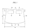
- FIGs. 1 to 3 are views showing an example of laminated glass obtained by a production method of the present invention.
- Laminated glass 10 includes a first glass plate 12, a second glass plate 14 facing the first glass plate 12 and an intermediate film 16 sandwiched between the first glass plate 12 and the second glass plate 14.
- the laminated glass 10 is subjected to bending processing so that the surface 10a side is formed in a concave shape. Further, two display panels 20 are bonded on the surface 10a of the laminated glass 10 with an adhesive.
- the maximum bending depth of the laminated glass 10 can be appropriately set depending on the use, and it is preferably from 5 to 60 mm and more preferably from 10 to 50 mm.
- the "maximum bending depth” is also called doubling, and is a maximum value of bending depth of laminated glass in which glass plates are curved in a concave shape by bending processing. It means the length of a perpendicular line drawn from a deepest point of a concave portion of the laminated glass to a straight line connecting facing peripheral edges to each other in the laminated glass, when the convex side of the laminated glass is directed downward.
- the "maximum bending depth" of the laminated glass 10 means the length d of a perpendicular line drawn from a deepest point a of a concave portion on the surface 10a of the first glass plate 12 of the laminated glass 10 to a straight line L connecting facing peripheral edges (an upper edge and a lower edge) to each other at the first glass plate 12 of the laminated glass 10, when the convex side of the laminated glass 10 is directed downward.
- Materials of the first glass plate 12 and the second glass plate 14 are not particularly limited, and include inorganic glass such as soda-lime glass, borosilicate glass, alkali-free glass and quartz glass.
- the materials of the first glass plate 12 and the second glass plate 14 may be the same or different from each other.
- the shape and the size of the first glass plate 12 and the second glass plate 14 are not particularly limited, and may be appropriately determined depending on the use such as windowpane of automobiles or windowpane of architectural structures.
- the planar shape of the first glass plate 12 and the second glass plate 14 of this embodiment is a shape in which a lower edge 11b side is wider than an upper edge 11a side. Further, the first glass plate 12 is curved so as to form a concave shape in which a central portion 12a is lower than a peripheral portion 12b, when the convex side of the laminated glass 10 is directed downward. Similarly, the second glass plate 14 is curved so as to form a concave shape in which a central portion 14a is lower than a peripheral portion 14b, when the convex side of the laminated glass 10 is directed downward.
- the shape of the first glass plate 12 and the shape of the second glass plate 14 are the same.
- the thickness of the first glass plate 12 and the second glass plate 14 can be appropriately determined depending on the use, and it is preferably from 0.5 to 3.0 mm and more preferably from 1.0 to 2.5 mm.
- the thickness of the first glass plate 12 and the second glass plate 14 may be the same or different from each other.
- the intermediate film 16 is sandwiched between the first glass plate 12 and the second glass plate 14.
- thermoplastic materials commonly used for intermediate films of laminated glass can be employed, and for example, polyvinyl butyral and the like may be mentioned.
- the intermediate film 16 may be either a single layer or a multilayer.
- the thickness of the intermediate film 16 is preferably from 0.2 to 1.0 mm and more preferably from 0.3 to 0.8 mm.
- the display panel 20 is bonded on the surface 10a of the laminated glass 10 with an adhesive.
- the display panel 20 is not particularly limited, and examples thereof include a liquid crystal panel.
- the use of the display panel 20 is not particularly limited.
- the display panel 20 may be allowed to act as a sun visor.
- the number, the shape and the size of the display panels 20 are not particularly limited, and may be appropriately determined depending on the use.
- a position at which the display panel 20 is bonded on the surface 10a of the laminated glass 10 is not particularly limited, and may be appropriately determined depending on the use.
- two rectangular display panels 20 are bonded laterally side by side on the upper edge 11a side on the surface 10a of the laminated glass 10.
- the use of the laminated glass is not particularly limited, and examples thereof include windowpane of vehicles such as automobiles, and windowpane of architectural structures.
- the method for producing the laminated glass 10 of this embodiment includes the following steps (1) to (3):
- the first glass plate 12 and the second glass plate 14 each having a curved shape can be produced by known methods. Examples thereof include a method of placing a flat plate-shaped glass plate obtained by known methods on a predetermined pattern which holds only a peripheral portion of the glass plate, followed by subjecting to bending processing in which the glass plate is heated at a temperature equal to or higher than the glass transition temperature thereof in a heating furnace or the like and then cooled. In the bending processing, a central portion of the heated glass plate, which is not held by the pattern, hangs down by gravity, thereby being formed to a concavely curved shape.
- a frame-shaped holder 100 exemplified in FIG. 5 which will be described below in a method ( ⁇ ) of the step (2), may also be used.
- the laminated glass 10 by heating and pressurizing the laminate 10A known methods can be employed, and for example, a method of press-bonding the laminate 10A under heating by using an autoclave, and the like may be mentioned.
- the heating temperature and the pressure may be appropriately set depending on the kind of the intermediate film.
- the laminate 10A may be preliminarily press-bonded.
- Methods for preliminarily press-bonding the laminate 10A include a method of heating the laminate 10A under reduced pressure.
- the display panels 20 are bonded on the surface 10A of the laminated glass 10 obtained in the step (1).
- the display panels 20 are coated with an adhesive on back sides thereof, attached to the surface 10a of the laminated glass 10, and bonded by heating.
- the adhesive one which can be bonded by heating can be used.
- examples thereof include a thermosetting adhesive tape.
- Methods for performing the post-processing with heating to the laminated glass 10 in the step (2) are not particularly limited. However, for example, the following method ( ⁇ ) or method ( ⁇ ) is preferred.
- the intermediate film 16 is softened, sometimes resulting in deformation of the laminated glass 10.
- deformation can be suppressed by employing the method ( ⁇ ) or the method ( ⁇ ).
- a method for holding at least a part of the peripheral portion 10b of the laminated glass 10 a method of placing the laminated glass 10 on a frame-shaped holder and holding at least a part of the peripheral portion 10b of the laminated glass 10 by the holder is preferred.
- examples thereof include a method of using a frame-shaped holder 100 exemplified in FIG. 5 .
- the holder 100 has a frame portion 110 having the same shape as the planar shape of the laminated glass 10 and a supporting portion 112 formed so as to project inward from the frame portion 110.
- the laminated glass 10 is placed on the holder 100 and held, the laminated glass 10 is fitted in the frame portion 110, and the peripheral portion 10b of the laminated glass 10 is supported from below by the supporting portion 112.
- Materials of the holder are not particularly limited, and for example, heat-resistant metal materials such as iron and stainless steel, and the like may be mentioned.
- the use of the same holder as used in the step (1) is preferred in that the cost for the holder can be suppressed, and in that the laminated glass 10 can be held in a desired shape.
- the frame-shaped holder is not limited to the above-mentioned holder 100.
- the holder may not hold the peripheral portion of the laminated glass over the whole periphery thereof.
- the holder may have a chipped portion so that the laminated glass can be mounted on the holder or removed from the holder by a carrying arm for carrying the laminated glass.
- a frame-shaped holder 100A shown in FIG. 6 may be used.
- the holder 100A is the same as the holder 100 except that two chipped portions 114 are formed in the frame portion 110 and the supporting portion 112, and a portion 100a positioned between the two chipped portions 114 and each of portions 100b on both sides of the chipped portions 114 are connected to each other by a connecting portion 116.
- the laminated glass 10 is carried in such a manner that the carrying arms are positioned in portions corresponding to the chipped portions 114 when the laminated glass 10 is placed on the holder 100A, and is placed on the holder 100A. At this time, the carrying arms come to the positions of the chipped portions 114 of the holder 100A, and therefore, the carrying arms do not contact with the frame portion 110 and the supporting portion 112 of the holder 100A. Further, after the post-processing with heating, the laminated glass 10 is held at the positions of the chipped portions 114 of the holder 100A by the carrying arms and removed. By performing work as described above, the laminated glass 10 can be easily mounted on the holder 100A and removed therefrom.
- the method ( ⁇ ) is not limited to the method of using the frame-shaped holder.
- it may be a method of using a mold in which a concave portion having a shape complementary to the shape of the laminated glass is formed, fitting the laminated glass in the concave portion of the mold, and performing the post-processing with heating while holding the whole surface of the laminated glass by the mold.
- a mode of leaning the laminated glass may be any as long as the laminated glass can be maintained in a state of leaning in performing the post-processing with heating, and is not particularly limited.
- Examples thereof include a mode of leaning the laminated glass 10 by supporting the peripheral portion 10b thereof at 3 points with a jig having supporting parts for supporting each of a total of 3 points of one point (a portion b in FIG. 7 ) at the center of the upper edge 11a of the peripheral portion 10b in the laminated glass 10 and 2 points (portions c and d in FIG. 7 ) on both end sides of the center of the lower edge 11b.
- the method ( ⁇ ) is preferred in that the deformation of the laminated glass is more easily suppressed, and in that the step (2) and the step (3) can be continuously smoothly performed while placing the laminated glass on the holder.
- the heating temperature in the step (2) is from 80 to 100°C.
- the heating temperature in the step (2) is equal to or higher than the lower limit value of the above-mentioned range, adhesive force of the thermosetting adhesive tape can be sufficiently exhibited.
- the heating temperature in the step (2) is equal to or lower than the upper limit value of the above-mentioned range, deterioration of the thermosetting adhesive tape can be prevented.
- Methods of heating the laminated glass are not particularly limited, and for example, an oven, a heating furnace and the like may be mentioned.
- the laminated glass heated in the step (2) is cooled while holding at least a part of the peripheral portion thereof.
- the laminated glass can be suppressed from being deformed at the time of cooling, even when the intermediate film is softened in the step (2).
- Methods for holding at least a part of the peripheral portion of the laminated glass in the step (3) include the same methods as mentioned in the method ( ⁇ ) of the step (2).
- the step (3) from the point that cooling can be efficiently performed while suppressing the deformation of the laminated glass, it is preferred to place the laminated glass 10 on the frame-shaped holder and to cool it while holding at least a part of the peripheral portion 10b of the laminated glass 10 by the holder.
- the step (3) using a mold in which a concave portion having a shape complementary to the shape of the laminated glass is formed, and fitting the laminated glass in the concave portion of the mold, the whole surface of the laminated glass may be held by the mold.
- the cooling of the step (3) is preferably performed in the state as it is.
- step (3) it is cooled to 60°C or lower, more preferably to 50°C or lower, still more preferably to 40°C or lower.
- the occurrence of deformation in the laminated glass obtained can be more stably suppressed by performing the cooling in the step (3) to a temperature equal to or lower than the above-mentioned upper limit value.
- Methods for cooling the laminated glass are not particularly limited, and for example, a method of using an air blower, and the like may be mentioned. Further, the laminated glass may be naturally cooled.
- the variation of the maximum bending depth of the laminated glass 10 obtained in the step (3) to the maximum bending depth of the laminated glass 10 obtained in the step (1) is preferably 5 mm or less, and more preferably 3 mm or less.
- the maximum bending depth of the laminated glass is measured by a depth gauge.
- the variation of the curvature of the laminated glass 10 obtained in the step (3) to the curvature of the laminated glass 10 obtained in the step (1) is preferably 2 mm or less, and more preferably 1 mm or less.
- the variation of the curvature is measured at each of 4 points in a plane of the laminated glass, and determined as an average value thereof.
- cooling is performed while holding at least a part of the peripheral portion of the laminated glass in the step (3), after the post-processing with heating is performed in the step (2). Accordingly, even when the intermediate film is softened by heating, the laminated glass in which the occurrence of deformation is suppressed can be obtained.
- the method for producing a laminated glass of the present invention even in the laminated glass having a curved shape, such as the laminated glass 10, the deformation thereof can be sufficiently suppressed. It is therefore effective for the production of windshield of vehicles, particularly for the production of windshield of automobiles.
- the method for producing a laminated glass of the present invention is not limited to the methods described above.
- the post-processing with heating in the step (2) may also be a method of performing processing of bonding a part other than the display panel, such as a room mirror base or a rain sensor, on the surface of the laminated glass, or may be a method of performing processing of forming an organic or inorganic cured film such as an UV-ray cutting film or a water-repellent film on the surface of the laminated glass.
- the laminated glass obtained in the step (1) has strain, it may be a method of correcting the deformation thereof by the post-processing with heating in the step (2) and the step (3).
- the production method of the present invention is particularly effective in the case where the laminated glass is required to be widely heated, such as the case of bonding the display panel and the like or the case of correcting the strain of the laminated glass.
- a flat plate-shaped glass plate of 1000 mm in length (length d1 in FIG. 1 ) ⁇ 1500 mm in width (length d2 in FIG. 1 ) ⁇ 2 mm in thickness having the same planar shape as the laminated glass 10 exemplified in FIG. 1 was placed on a frame-shaped stainless steel holder 100 ( FIG. 5 ) having the same shape as the glass plate.
- the glass plate is supported only at a peripheral portion thereof by the holder 100.
- the glass plate was carried in this state into a heating furnace by a carrying conveyor, and heated by a heater in the heating furnace.
- the laminated glass 10 obtained was supported at each of a total of 3 points of one point (the portion b in FIG. 7 ) at the center of the upper edge of the peripheral portion 10b thereof and 2 points (the portions c and d in FIG. 7 ) on both end sides of the center of the lower edge, and was leaned on a carriage so that the longitudinal direction of the laminated glass 10 was vertically directed. In this state, the laminated glass was heated in an oven at an atmospheric temperature of 100°C for 30 minutes. (Step (2))
- the laminated glass heated in the step (2) was placed on a holder 100 with a surface on the convex side thereof directed downward, and cooled to 40°C in a state where a peripheral portion of the laminated glass was held by the holder 100. (Step 3)
- Laminated glass was obtained in the same manner as in Example 1, except that in the step (2), the laminated glass 10 was heated in the oven at an atmospheric temperature of 100°C for 30 minutes in a state where it was placed on the holder 100.
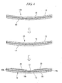
- Laminated glass was obtained in the same manner as in Example 1, except that in the step (2) and the step (3), heating and cooling were performed in a state where the laminated glass 10 was supported from below at both sides of the center portion in a lateral direction on a surface of the concave side thereof by two pipes 200 made of SUS, as shown in FIG. 8 , and that it was cooled to 40°C in the step (3).
- this pattern is hereinafter also described as a pattern A
- the laminated glass obtained in the step (3) of each Example was placed on the concave portion of the pattern A, and the variation of the curvature based on the pattern A was measured by using a thickness gauge or a taper gauge.
- the curvature of a bottom surface of the concave portion of the pattern A is the same as the curvature of the laminated glass obtained in the step (1), and the variation of the curvature based on the pattern A is the same as the variation of the curvature of the laminated glass obtained in the step (3) to the curvature of the laminated glass obtained in the step (1).
- Measuring points were 4 points of corners of No. 1 to No. 4 shown in FIG. 7 in the laminated glass.
- the laminated glass was held with the convex side thereof directed downward, and a depth gauge was installed so as to bridge a center portion of an upper edge of the laminated glass and a center portion of a lower edge thereof.
- the distance from the deepest point of the concave portion of the laminated glass to the depth gauge was measured as the maximum bending depth.
Landscapes
- Physics & Mathematics (AREA)
- Fluid Mechanics (AREA)
- Engineering & Computer Science (AREA)
- Mechanical Engineering (AREA)
- Joining Of Glass To Other Materials (AREA)
Claims (9)
- Verfahren zur Herstellung eines Verbundglases, das eine erste Glasplatte, eine zweite Glasplatte, die der ersten Glasplatte gegenüberliegt, und einen Zwischenfilm, der zwischen der ersten Glasplatte und der zweiten Glasplatte eingeschoben ist, umfasst, wobei das Verfahren die nachstehenden Schritte (1) bis (3) umfasst:(1) einen Schritt des Laminierens der ersten Glasplatte, des Zwischenfilms und der zweiten Glasplatte in dieser Reihenfolge, um ein Laminat zu bilden, und des Erwärmens und Druckbeaufschlagens des Laminats, um ein Verbundglas zu erhalten;(2) einen Schritt des Durchführens einer Nachbearbeitung mit Erwärmen des in Schritt (1) erhaltenen Verbundglases; und(3) einen Schritt des Abkühlens des Verbundglases, während mindestens ein Teil eines Umfangsabschnitts des Verbundglases gehalten wird, nach dem Schritt (2);wobei eine Erwärmungstemperatur in dem Schritt (2) von 80 bis 100°C beträgt,
wobei in dem Schritt (3) das Verbundglas auf 60°C oder weniger abgekühlt wird, und
wobei die Nachbearbeitung mit Erwärmen in Schritt (2) ein Verfahren zur Durchführung der Bearbeitung des Verbindens einer Anzeigeplatte, einer Raumspiegelbasis oder eines Regensensors auf eine Oberfläche des Verbundglases, oder ein Verfahren zur Durchführung der Bearbeitung des Bildens eines organischen und anorganischen gehärteten Films auf der Oberfläche des Verbundglases ist. - Verfahren zur Herstellung eines Verbundglases nach Anspruch 1, wobei in dem Schritt (3) das Verbundglas auf einen rahmenförmigen Halter gesetzt wird und mindestens ein Teil des Umfangabschnitts des Verbundglases von dem Halter gehalten wird.
- Verfahren zur Herstellung eines Verbundglases nach Anspruch 1 oder 2, wobei in dem Schritt (2) die Nachbearbeitung mit Erwärmen durchgeführt wird, während mindestens ein Teil des Umfangsabschnitts des Verbundglases gehalten wird.
- Verfahren zur Herstellung eines Verbundglases nach Anspruch 3, wobei in dem Schritt (2) das Verbundglas auf einen rahmenförmigen Halter gesetzt wird und mindestens ein Teil des Umfangabschnitts des Verbundglases von dem Halter gehalten wird.
- Verfahren zur Herstellung eines Verbundglases nach Anspruch 1 oder 2, wobei in dem Schritt (2) die Nachbearbeitung mit Erwärmen in einem Zustand durchgeführt wird, in dem das Verbundglas gelagert ist.
- Verfahren zur Herstellung eines Verbundglases nach einem der Ansprüche 1 bis 5, wobei eine Abweichung einer maximalen Biegetiefe des in dem Schritt (3) erhaltenen Verbundglases zu einer maximalen Biegetiefe des in dem Schritt (1) erhaltenen Verbundglases, wie gemäß der Beschreibung bestimmt, 5 mm oder weniger beträgt.
- Verfahren zur Herstellung eines Verbundglases nach einem der Ansprüche 1 bis 6, wobei eine Abweichung einer Krümmung des in dem Schritt (3) erhaltenen Verbundglases zu einer Krümmung des in dem Schritt (1) erhaltenen Verbundglases, wie gemäß der Beschreibung bestimmt, 1 mm oder weniger beträgt.
- Verfahren zur Herstellung eines Verbundglases nach einem der Ansprüche 1 bis 7, wobei das Verbundglas ein Verbundglas für eine Windschutzscheibe eines Fahrzeugs ist.
- Verfahren zur Herstellung eines Verbundglases nach Anspruch 8, wobei das Fahrzeug ein Automobil ist.
Applications Claiming Priority (2)
| Application Number | Priority Date | Filing Date | Title |
|---|---|---|---|
| JP2014020677 | 2014-02-05 | ||
| PCT/JP2015/053226 WO2015119192A1 (ja) | 2014-02-05 | 2015-02-05 | 合わせガラスの製造方法 |
Publications (3)
| Publication Number | Publication Date |
|---|---|
| EP3103777A1 EP3103777A1 (de) | 2016-12-14 |
| EP3103777A4 EP3103777A4 (de) | 2017-10-11 |
| EP3103777B1 true EP3103777B1 (de) | 2021-03-24 |
Family
ID=53777993
Family Applications (1)
| Application Number | Title | Priority Date | Filing Date |
|---|---|---|---|
| EP15746828.1A Not-in-force EP3103777B1 (de) | 2014-02-05 | 2015-02-05 | Verbundglasherstellungsverfahren |
Country Status (5)
| Country | Link |
|---|---|
| US (1) | US20160332423A1 (de) |
| EP (1) | EP3103777B1 (de) |
| JP (1) | JP6428651B2 (de) |
| CN (1) | CN105960384B (de) |
| WO (1) | WO2015119192A1 (de) |
Families Citing this family (10)
| Publication number | Priority date | Publication date | Assignee | Title |
|---|---|---|---|---|
| JP6658760B2 (ja) * | 2015-09-03 | 2020-03-04 | Agc株式会社 | 透明スクリーン、透明スクリーン組立体、透明スクリーンの製造方法、および透明スクリーン組立体の製造方法 |
| CN110461781B (zh) | 2017-02-20 | 2022-11-15 | 康宁公司 | 成形玻璃层合物及其形成方法 |
| WO2018186091A1 (ja) * | 2017-04-04 | 2018-10-11 | Agc株式会社 | 自動車用フロントベンチガラス |
| US10752095B2 (en) * | 2017-04-27 | 2020-08-25 | Optic Armor, LLC | Window |
| CN107962852A (zh) * | 2017-10-18 | 2018-04-27 | 辽宁乐威科技发展有限公司 | 一种夹层玻璃生产线 |
| CN111278781B (zh) | 2017-10-18 | 2022-10-11 | 康宁股份有限公司 | 在共下垂期间控制玻璃之间的分离以减少玻璃之间的最终形状错配的方法 |
| CN108312668B (zh) | 2018-01-25 | 2019-12-13 | 常州亚玛顿股份有限公司 | 一种夹层曲面玻璃复合材料及其制造方法 |
| CN108178529B (zh) | 2018-01-25 | 2019-12-13 | 常州亚玛顿股份有限公司 | 一种夹层曲面玻璃的制造方法 |
| DE102019110918A1 (de) * | 2018-06-18 | 2019-12-19 | Technische Universität Bergakademie Freiberg | Verfahren zur Herstellung von Funktionsverbundgläsern, Verfahren zur Anordnung von Glaselementen für Funktionsverbundgläser und Anordnung von Glaselementen für Funktionsverbundgläser |
| CN112358204A (zh) * | 2020-11-13 | 2021-02-12 | 信义玻璃工程(东莞)有限公司 | 夹层玻璃的制作方法及夹层玻璃 |
Family Cites Families (30)
| Publication number | Priority date | Publication date | Assignee | Title |
|---|---|---|---|---|
| BE554624A (de) * | 1955-08-19 | 1900-01-01 | ||
| US3231440A (en) * | 1958-07-17 | 1966-01-25 | Libbey Owens Ford Glass Co | Method of laminating glass |
| US3242026A (en) * | 1964-07-20 | 1966-03-22 | Ford Motor Co | Method of bonding a conducting element to a nonconducting element |
| US3562366A (en) * | 1968-12-18 | 1971-02-09 | Minnesota Mining & Mfg | Method of repairing windshields |
| US3841932A (en) * | 1973-04-16 | 1974-10-15 | C Forler | Method and apparatus for repairing cracks in windshields |
| GB1470959A (en) * | 1973-06-04 | 1977-04-21 | Triplex Safety Glass Co | Manufacture of laminated glass articles |
| DE2731100C3 (de) * | 1977-07-09 | 1980-11-20 | Vereinigte Glaswerke Gmbh, 5100 Aachen | Verfahren zum Verkleben von Metallteilen mit Glasoberflächen, insbesondere zum Verkleben von Halteelementen für einen Rückspiegel und einer Windschutzscheibe |
| DE3854693T2 (de) * | 1987-12-24 | 1996-07-18 | Asahi Glass Co Ltd | Struktur und verfahren zum aufbringen einer spiegelbasis auf ein glasblatt. |
| IT1230916B (it) * | 1988-06-27 | 1991-11-08 | Central Glass Co Ltd | Dispositivo e metodo per tagliare parte di bordo superfluo di interstrato di vetro laminato |
| US4954300A (en) * | 1989-06-14 | 1990-09-04 | John E. Vandigriff | Glass repair method and apparatus |
| US5095639A (en) * | 1989-11-20 | 1992-03-17 | Slavin Jr Barry C | Method of drying windshield shatter crack cavities using a hand-held radiant heating device |
| US5109632A (en) * | 1990-04-03 | 1992-05-05 | Ppg Industries, Inc. | Automatic interlayer trimming |
| JP2565172Y2 (ja) * | 1992-08-07 | 1998-03-11 | 新東工業株式会社 | 液晶パネル製造用治具装置 |
| JP3013662U (ja) * | 1995-01-13 | 1995-07-18 | 貴 伊藤 | セパレート式カーナビゲーションシステム |
| JPH09227162A (ja) * | 1995-12-22 | 1997-09-02 | Toto Ltd | 雨天視界確保性乗物用ガラス、それを備えた自動車 |
| DE19711459A1 (de) * | 1997-03-19 | 1998-09-24 | Flachglas Automotive Gmbh | Verfahren zur Herstellung einer gebogenen Verbundsicherheitsglasscheibe |
| DE19712145C1 (de) * | 1997-03-22 | 1998-04-23 | Sekurit Saint Gobain Deutsch | Verfahren zur Herstellung einer Verbundglasscheibe und Vorrichtung zur Durchführung des Verfahrens |
| CN2353749Y (zh) * | 1997-10-14 | 1999-12-15 | 广东伦教汽车玻璃有限公司 | 夹层玻璃真空处理装置 |
| US6368664B1 (en) * | 1999-05-03 | 2002-04-09 | Guardian Industries Corp. | Method of ion beam milling substrate prior to depositing diamond like carbon layer thereon |
| US6602371B2 (en) * | 2001-02-27 | 2003-08-05 | Guardian Industries Corp. | Method of making a curved vehicle windshield |
| JP3638532B2 (ja) * | 2001-03-29 | 2005-04-13 | 三菱樹脂株式会社 | 防火性合わせガラス |
| JP4811774B2 (ja) * | 2001-04-10 | 2011-11-09 | 旭硝子株式会社 | ガラス板曲げ成形装置および成形方法 |
| JP2003020236A (ja) * | 2001-07-04 | 2003-01-24 | Nippon Sheet Glass Co Ltd | ガラス板の自重曲げ分割成形型の設計方法 |
| CN1690005A (zh) * | 2004-04-23 | 2005-11-02 | 阳光也 | 高强度防弹夹层玻璃的制造方法 |
| CN201058843Y (zh) * | 2007-06-25 | 2008-05-14 | 福耀集团(上海)汽车玻璃有限公司 | 夹层玻璃加热成型模具 |
| JP2009190947A (ja) * | 2008-02-15 | 2009-08-27 | Sekisui Chem Co Ltd | 合わせガラスの製造方法及び合わせガラス |
| WO2010047273A1 (ja) * | 2008-10-23 | 2010-04-29 | 旭硝子株式会社 | ガラス基板積層装置及び積層ガラス基板の製造方法 |
| EP2695864B1 (de) * | 2011-04-01 | 2019-07-03 | AGC Inc. | Laminiertes glas und verfahren zu seiner herstellung |
| JP5241976B1 (ja) * | 2011-10-04 | 2013-07-17 | 株式会社クラレ | 複数のポリビニルアセタール樹脂層が積層した積層体 |
| CN102795793B (zh) * | 2012-09-11 | 2014-09-24 | 福耀玻璃工业集团股份有限公司 | 一种可电加热的低辐射镀膜夹层玻璃 |
-
2015
- 2015-02-05 EP EP15746828.1A patent/EP3103777B1/de not_active Not-in-force
- 2015-02-05 JP JP2015561025A patent/JP6428651B2/ja active Active
- 2015-02-05 CN CN201580006936.8A patent/CN105960384B/zh active Active
- 2015-02-05 WO PCT/JP2015/053226 patent/WO2015119192A1/ja active Application Filing
-
2016
- 2016-08-01 US US15/225,072 patent/US20160332423A1/en not_active Abandoned
Non-Patent Citations (1)
| Title |
|---|
| None * |
Also Published As
| Publication number | Publication date |
|---|---|
| US20160332423A1 (en) | 2016-11-17 |
| EP3103777A4 (de) | 2017-10-11 |
| WO2015119192A1 (ja) | 2015-08-13 |
| EP3103777A1 (de) | 2016-12-14 |
| JP6428651B2 (ja) | 2018-11-28 |
| JPWO2015119192A1 (ja) | 2017-03-23 |
| CN105960384B (zh) | 2019-04-02 |
| CN105960384A (zh) | 2016-09-21 |
Similar Documents
| Publication | Publication Date | Title |
|---|---|---|
| EP3103777B1 (de) | Verbundglasherstellungsverfahren | |
| US11400691B2 (en) | Methods of forming shaped glass articles from glass sheets | |
| JP7163336B2 (ja) | ガラス基板へのエレクトロクロミックデバイスの積層 | |
| US7143800B2 (en) | Non-autoclave laminated glass | |
| US11192341B2 (en) | Method for producing a curved composite glass pane having a thin glass pane | |
| EP4245526A2 (de) | Kaltgeformte laminate | |
| EP1874700B1 (de) | Verfahren und vorrichtung zum verstärken der kanten einer oder mehrerer glasplatten | |
| US7459199B2 (en) | Method of and apparatus for strengthening edges of one or more glass sheets | |
| US20150122406A1 (en) | Process for laminating thin glass laminates | |
| US12036847B2 (en) | Vehicle glazing having a sharply curved portion and the method for bending | |
| JP4475443B2 (ja) | 曲げ合わせガラスの製造方法 | |
| CN116442606A (zh) | 一种制备夹层窗玻璃的方法 | |
| JP7169311B2 (ja) | 局所冷却を含むガラス板の曲げ | |
| EP2380736B1 (de) | Verfahren und Vorrichtung zum Abbau von beschichteten Verglasungen oder von Photovoltaikmodulen | |
| CN108178529A (zh) | 一种夹层曲面玻璃的制造方法 | |
| US7775068B2 (en) | Production method and production device for laminated glass | |
| US11511526B2 (en) | Aligning and laminating method for the production of thin laminated glass from glass panes which do not fit together accurately | |
| CN110582468B (zh) | 玻璃制品的形成方法和由此形成的玻璃制品 | |
| CN214477497U (zh) | 一种冷弯成型多层玻璃制品及其成型工装 | |
| KR20220103784A (ko) | 액정 패널에서 균일한 투과율을 위한 시스템 및 방법 | |
| JPH02120260A (ja) | 合わせガラスの製造方法 |
Legal Events
| Date | Code | Title | Description |
|---|---|---|---|
| PUAI | Public reference made under article 153(3) epc to a published international application that has entered the european phase |
Free format text: ORIGINAL CODE: 0009012 |
|
| STAA | Information on the status of an ep patent application or granted ep patent |
Free format text: STATUS: REQUEST FOR EXAMINATION WAS MADE |
|
| 17P | Request for examination filed |
Effective date: 20160804 |
|
| AK | Designated contracting states |
Kind code of ref document: A1 Designated state(s): AL AT BE BG CH CY CZ DE DK EE ES FI FR GB GR HR HU IE IS IT LI LT LU LV MC MK MT NL NO PL PT RO RS SE SI SK SM TR |
|
| AX | Request for extension of the european patent |
Extension state: BA ME |
|
| DAX | Request for extension of the european patent (deleted) | ||
| A4 | Supplementary search report drawn up and despatched |
Effective date: 20170911 |
|
| RIC1 | Information provided on ipc code assigned before grant |
Ipc: B32B 17/10 20060101ALI20170905BHEP Ipc: C03C 27/12 20060101AFI20170905BHEP |
|
| RAP1 | Party data changed (applicant data changed or rights of an application transferred) |
Owner name: AGC INC. |
|
| STAA | Information on the status of an ep patent application or granted ep patent |
Free format text: STATUS: EXAMINATION IS IN PROGRESS |
|
| 17Q | First examination report despatched |
Effective date: 20200312 |
|
| GRAP | Despatch of communication of intention to grant a patent |
Free format text: ORIGINAL CODE: EPIDOSNIGR1 |
|
| STAA | Information on the status of an ep patent application or granted ep patent |
Free format text: STATUS: GRANT OF PATENT IS INTENDED |
|
| INTG | Intention to grant announced |
Effective date: 20201006 |
|
| STAA | Information on the status of an ep patent application or granted ep patent |
Free format text: STATUS: GRANT OF PATENT IS INTENDED |
|
| GRAS | Grant fee paid |
Free format text: ORIGINAL CODE: EPIDOSNIGR3 |
|
| GRAA | (expected) grant |
Free format text: ORIGINAL CODE: 0009210 |
|
| STAA | Information on the status of an ep patent application or granted ep patent |
Free format text: STATUS: THE PATENT HAS BEEN GRANTED |
|
| AK | Designated contracting states |
Kind code of ref document: B1 Designated state(s): AL AT BE BG CH CY CZ DE DK EE ES FI FR GB GR HR HU IE IS IT LI LT LU LV MC MK MT NL NO PL PT RO RS SE SI SK SM TR |
|
| REG | Reference to a national code |
Ref country code: GB Ref legal event code: FG4D |
|
| REG | Reference to a national code |
Ref country code: CH Ref legal event code: EP |
|
| REG | Reference to a national code |
Ref country code: DE Ref legal event code: R096 Ref document number: 602015067205 Country of ref document: DE |
|
| REG | Reference to a national code |
Ref country code: IE Ref legal event code: FG4D |
|
| REG | Reference to a national code |
Ref country code: AT Ref legal event code: REF Ref document number: 1374346 Country of ref document: AT Kind code of ref document: T Effective date: 20210415 |
|
| REG | Reference to a national code |
Ref country code: LT Ref legal event code: MG9D |
|
| PG25 | Lapsed in a contracting state [announced via postgrant information from national office to epo] |
Ref country code: NO Free format text: LAPSE BECAUSE OF FAILURE TO SUBMIT A TRANSLATION OF THE DESCRIPTION OR TO PAY THE FEE WITHIN THE PRESCRIBED TIME-LIMIT Effective date: 20210624 Ref country code: BG Free format text: LAPSE BECAUSE OF FAILURE TO SUBMIT A TRANSLATION OF THE DESCRIPTION OR TO PAY THE FEE WITHIN THE PRESCRIBED TIME-LIMIT Effective date: 20210624 Ref country code: FI Free format text: LAPSE BECAUSE OF FAILURE TO SUBMIT A TRANSLATION OF THE DESCRIPTION OR TO PAY THE FEE WITHIN THE PRESCRIBED TIME-LIMIT Effective date: 20210324 Ref country code: HR Free format text: LAPSE BECAUSE OF FAILURE TO SUBMIT A TRANSLATION OF THE DESCRIPTION OR TO PAY THE FEE WITHIN THE PRESCRIBED TIME-LIMIT Effective date: 20210324 Ref country code: GR Free format text: LAPSE BECAUSE OF FAILURE TO SUBMIT A TRANSLATION OF THE DESCRIPTION OR TO PAY THE FEE WITHIN THE PRESCRIBED TIME-LIMIT Effective date: 20210625 |
|
| PG25 | Lapsed in a contracting state [announced via postgrant information from national office to epo] |
Ref country code: RS Free format text: LAPSE BECAUSE OF FAILURE TO SUBMIT A TRANSLATION OF THE DESCRIPTION OR TO PAY THE FEE WITHIN THE PRESCRIBED TIME-LIMIT Effective date: 20210324 Ref country code: LV Free format text: LAPSE BECAUSE OF FAILURE TO SUBMIT A TRANSLATION OF THE DESCRIPTION OR TO PAY THE FEE WITHIN THE PRESCRIBED TIME-LIMIT Effective date: 20210324 Ref country code: SE Free format text: LAPSE BECAUSE OF FAILURE TO SUBMIT A TRANSLATION OF THE DESCRIPTION OR TO PAY THE FEE WITHIN THE PRESCRIBED TIME-LIMIT Effective date: 20210324 |
|
| REG | Reference to a national code |
Ref country code: NL Ref legal event code: MP Effective date: 20210324 |
|
| REG | Reference to a national code |
Ref country code: AT Ref legal event code: MK05 Ref document number: 1374346 Country of ref document: AT Kind code of ref document: T Effective date: 20210324 |
|
| PG25 | Lapsed in a contracting state [announced via postgrant information from national office to epo] |
Ref country code: NL Free format text: LAPSE BECAUSE OF FAILURE TO SUBMIT A TRANSLATION OF THE DESCRIPTION OR TO PAY THE FEE WITHIN THE PRESCRIBED TIME-LIMIT Effective date: 20210324 |
|
| PG25 | Lapsed in a contracting state [announced via postgrant information from national office to epo] |
Ref country code: CZ Free format text: LAPSE BECAUSE OF FAILURE TO SUBMIT A TRANSLATION OF THE DESCRIPTION OR TO PAY THE FEE WITHIN THE PRESCRIBED TIME-LIMIT Effective date: 20210324 Ref country code: EE Free format text: LAPSE BECAUSE OF FAILURE TO SUBMIT A TRANSLATION OF THE DESCRIPTION OR TO PAY THE FEE WITHIN THE PRESCRIBED TIME-LIMIT Effective date: 20210324 Ref country code: LT Free format text: LAPSE BECAUSE OF FAILURE TO SUBMIT A TRANSLATION OF THE DESCRIPTION OR TO PAY THE FEE WITHIN THE PRESCRIBED TIME-LIMIT Effective date: 20210324 Ref country code: AT Free format text: LAPSE BECAUSE OF FAILURE TO SUBMIT A TRANSLATION OF THE DESCRIPTION OR TO PAY THE FEE WITHIN THE PRESCRIBED TIME-LIMIT Effective date: 20210324 Ref country code: SM Free format text: LAPSE BECAUSE OF FAILURE TO SUBMIT A TRANSLATION OF THE DESCRIPTION OR TO PAY THE FEE WITHIN THE PRESCRIBED TIME-LIMIT Effective date: 20210324 |
|
| PG25 | Lapsed in a contracting state [announced via postgrant information from national office to epo] |
Ref country code: IS Free format text: LAPSE BECAUSE OF FAILURE TO SUBMIT A TRANSLATION OF THE DESCRIPTION OR TO PAY THE FEE WITHIN THE PRESCRIBED TIME-LIMIT Effective date: 20210724 Ref country code: PT Free format text: LAPSE BECAUSE OF FAILURE TO SUBMIT A TRANSLATION OF THE DESCRIPTION OR TO PAY THE FEE WITHIN THE PRESCRIBED TIME-LIMIT Effective date: 20210726 Ref country code: PL Free format text: LAPSE BECAUSE OF FAILURE TO SUBMIT A TRANSLATION OF THE DESCRIPTION OR TO PAY THE FEE WITHIN THE PRESCRIBED TIME-LIMIT Effective date: 20210324 Ref country code: ES Free format text: LAPSE BECAUSE OF FAILURE TO SUBMIT A TRANSLATION OF THE DESCRIPTION OR TO PAY THE FEE WITHIN THE PRESCRIBED TIME-LIMIT Effective date: 20210324 Ref country code: RO Free format text: LAPSE BECAUSE OF FAILURE TO SUBMIT A TRANSLATION OF THE DESCRIPTION OR TO PAY THE FEE WITHIN THE PRESCRIBED TIME-LIMIT Effective date: 20210324 Ref country code: SK Free format text: LAPSE BECAUSE OF FAILURE TO SUBMIT A TRANSLATION OF THE DESCRIPTION OR TO PAY THE FEE WITHIN THE PRESCRIBED TIME-LIMIT Effective date: 20210324 |
|
| REG | Reference to a national code |
Ref country code: DE Ref legal event code: R097 Ref document number: 602015067205 Country of ref document: DE |
|
| PG25 | Lapsed in a contracting state [announced via postgrant information from national office to epo] |
Ref country code: AL Free format text: LAPSE BECAUSE OF FAILURE TO SUBMIT A TRANSLATION OF THE DESCRIPTION OR TO PAY THE FEE WITHIN THE PRESCRIBED TIME-LIMIT Effective date: 20210324 Ref country code: DK Free format text: LAPSE BECAUSE OF FAILURE TO SUBMIT A TRANSLATION OF THE DESCRIPTION OR TO PAY THE FEE WITHIN THE PRESCRIBED TIME-LIMIT Effective date: 20210324 |
|
| PLBE | No opposition filed within time limit |
Free format text: ORIGINAL CODE: 0009261 |
|
| STAA | Information on the status of an ep patent application or granted ep patent |
Free format text: STATUS: NO OPPOSITION FILED WITHIN TIME LIMIT |
|
| PG25 | Lapsed in a contracting state [announced via postgrant information from national office to epo] |
Ref country code: SI Free format text: LAPSE BECAUSE OF FAILURE TO SUBMIT A TRANSLATION OF THE DESCRIPTION OR TO PAY THE FEE WITHIN THE PRESCRIBED TIME-LIMIT Effective date: 20210324 |
|
| 26N | No opposition filed |
Effective date: 20220104 |
|
| PG25 | Lapsed in a contracting state [announced via postgrant information from national office to epo] |
Ref country code: IS Free format text: LAPSE BECAUSE OF FAILURE TO SUBMIT A TRANSLATION OF THE DESCRIPTION OR TO PAY THE FEE WITHIN THE PRESCRIBED TIME-LIMIT Effective date: 20210724 |
|
| PG25 | Lapsed in a contracting state [announced via postgrant information from national office to epo] |
Ref country code: MC Free format text: LAPSE BECAUSE OF FAILURE TO SUBMIT A TRANSLATION OF THE DESCRIPTION OR TO PAY THE FEE WITHIN THE PRESCRIBED TIME-LIMIT Effective date: 20210324 |
|
| REG | Reference to a national code |
Ref country code: CH Ref legal event code: PL |
|
| REG | Reference to a national code |
Ref country code: BE Ref legal event code: MM Effective date: 20220228 |
|
| GBPC | Gb: european patent ceased through non-payment of renewal fee |
Effective date: 20220205 |
|
| PG25 | Lapsed in a contracting state [announced via postgrant information from national office to epo] |
Ref country code: LU Free format text: LAPSE BECAUSE OF NON-PAYMENT OF DUE FEES Effective date: 20220205 |
|
| PG25 | Lapsed in a contracting state [announced via postgrant information from national office to epo] |
Ref country code: FR Free format text: LAPSE BECAUSE OF NON-PAYMENT OF DUE FEES Effective date: 20220228 |
|
| PG25 | Lapsed in a contracting state [announced via postgrant information from national office to epo] |
Ref country code: LI Free format text: LAPSE BECAUSE OF NON-PAYMENT OF DUE FEES Effective date: 20220228 Ref country code: IT Free format text: LAPSE BECAUSE OF FAILURE TO SUBMIT A TRANSLATION OF THE DESCRIPTION OR TO PAY THE FEE WITHIN THE PRESCRIBED TIME-LIMIT Effective date: 20210324 Ref country code: IE Free format text: LAPSE BECAUSE OF NON-PAYMENT OF DUE FEES Effective date: 20220205 Ref country code: GB Free format text: LAPSE BECAUSE OF NON-PAYMENT OF DUE FEES Effective date: 20220205 Ref country code: CH Free format text: LAPSE BECAUSE OF NON-PAYMENT OF DUE FEES Effective date: 20220228 |
|
| PG25 | Lapsed in a contracting state [announced via postgrant information from national office to epo] |
Ref country code: BE Free format text: LAPSE BECAUSE OF NON-PAYMENT OF DUE FEES Effective date: 20220228 |
|
| PGFP | Annual fee paid to national office [announced via postgrant information from national office to epo] |
Ref country code: DE Payment date: 20230216 Year of fee payment: 9 |
|
| PG25 | Lapsed in a contracting state [announced via postgrant information from national office to epo] |
Ref country code: HU Free format text: LAPSE BECAUSE OF FAILURE TO SUBMIT A TRANSLATION OF THE DESCRIPTION OR TO PAY THE FEE WITHIN THE PRESCRIBED TIME-LIMIT; INVALID AB INITIO Effective date: 20150205 |
|
| PG25 | Lapsed in a contracting state [announced via postgrant information from national office to epo] |
Ref country code: MK Free format text: LAPSE BECAUSE OF FAILURE TO SUBMIT A TRANSLATION OF THE DESCRIPTION OR TO PAY THE FEE WITHIN THE PRESCRIBED TIME-LIMIT Effective date: 20210324 Ref country code: CY Free format text: LAPSE BECAUSE OF FAILURE TO SUBMIT A TRANSLATION OF THE DESCRIPTION OR TO PAY THE FEE WITHIN THE PRESCRIBED TIME-LIMIT Effective date: 20210324 |
|
| PG25 | Lapsed in a contracting state [announced via postgrant information from national office to epo] |
Ref country code: TR Free format text: LAPSE BECAUSE OF FAILURE TO SUBMIT A TRANSLATION OF THE DESCRIPTION OR TO PAY THE FEE WITHIN THE PRESCRIBED TIME-LIMIT Effective date: 20210324 |
|
| REG | Reference to a national code |
Ref country code: DE Ref legal event code: R119 Ref document number: 602015067205 Country of ref document: DE |
|
| PG25 | Lapsed in a contracting state [announced via postgrant information from national office to epo] |
Ref country code: MT Free format text: LAPSE BECAUSE OF FAILURE TO SUBMIT A TRANSLATION OF THE DESCRIPTION OR TO PAY THE FEE WITHIN THE PRESCRIBED TIME-LIMIT Effective date: 20210324 |