EP3103544B1 - Temperaturgesteuertes stickstofferzeugungssystem und verfahren zur erzeugung von mit stickstoff angereicherter luft - Google Patents
Temperaturgesteuertes stickstofferzeugungssystem und verfahren zur erzeugung von mit stickstoff angereicherter luft Download PDFInfo
- Publication number
- EP3103544B1 EP3103544B1 EP16174189.7A EP16174189A EP3103544B1 EP 3103544 B1 EP3103544 B1 EP 3103544B1 EP 16174189 A EP16174189 A EP 16174189A EP 3103544 B1 EP3103544 B1 EP 3103544B1
- Authority
- EP
- European Patent Office
- Prior art keywords
- air
- temperature
- flow
- nitrogen
- heat exchanger
- Prior art date
- Legal status (The legal status is an assumption and is not a legal conclusion. Google has not performed a legal analysis and makes no representation as to the accuracy of the status listed.)
- Active
Links
Images


Classifications
-
- B—PERFORMING OPERATIONS; TRANSPORTING
- B01—PHYSICAL OR CHEMICAL PROCESSES OR APPARATUS IN GENERAL
- B01D—SEPARATION
- B01D53/00—Separation of gases or vapours; Recovering vapours of volatile solvents from gases; Chemical or biological purification of waste gases, e.g. engine exhaust gases, smoke, fumes, flue gases, aerosols
- B01D53/30—Controlling by gas-analysis apparatus
-
- B—PERFORMING OPERATIONS; TRANSPORTING
- B01—PHYSICAL OR CHEMICAL PROCESSES OR APPARATUS IN GENERAL
- B01D—SEPARATION
- B01D53/00—Separation of gases or vapours; Recovering vapours of volatile solvents from gases; Chemical or biological purification of waste gases, e.g. engine exhaust gases, smoke, fumes, flue gases, aerosols
- B01D53/22—Separation of gases or vapours; Recovering vapours of volatile solvents from gases; Chemical or biological purification of waste gases, e.g. engine exhaust gases, smoke, fumes, flue gases, aerosols by diffusion
-
- B—PERFORMING OPERATIONS; TRANSPORTING
- B01—PHYSICAL OR CHEMICAL PROCESSES OR APPARATUS IN GENERAL
- B01D—SEPARATION
- B01D53/00—Separation of gases or vapours; Recovering vapours of volatile solvents from gases; Chemical or biological purification of waste gases, e.g. engine exhaust gases, smoke, fumes, flue gases, aerosols
- B01D53/22—Separation of gases or vapours; Recovering vapours of volatile solvents from gases; Chemical or biological purification of waste gases, e.g. engine exhaust gases, smoke, fumes, flue gases, aerosols by diffusion
- B01D53/228—Separation of gases or vapours; Recovering vapours of volatile solvents from gases; Chemical or biological purification of waste gases, e.g. engine exhaust gases, smoke, fumes, flue gases, aerosols by diffusion characterised by specific membranes
-
- B—PERFORMING OPERATIONS; TRANSPORTING
- B64—AIRCRAFT; AVIATION; COSMONAUTICS
- B64D—EQUIPMENT FOR FITTING IN OR TO AIRCRAFT; FLIGHT SUITS; PARACHUTES; ARRANGEMENT OR MOUNTING OF POWER PLANTS OR PROPULSION TRANSMISSIONS IN AIRCRAFT
- B64D37/00—Arrangements in connection with fuel supply for power plant
- B64D37/32—Safety measures not otherwise provided for, e.g. preventing explosive conditions
-
- B—PERFORMING OPERATIONS; TRANSPORTING
- B01—PHYSICAL OR CHEMICAL PROCESSES OR APPARATUS IN GENERAL
- B01D—SEPARATION
- B01D53/00—Separation of gases or vapours; Recovering vapours of volatile solvents from gases; Chemical or biological purification of waste gases, e.g. engine exhaust gases, smoke, fumes, flue gases, aerosols
- B01D53/22—Separation of gases or vapours; Recovering vapours of volatile solvents from gases; Chemical or biological purification of waste gases, e.g. engine exhaust gases, smoke, fumes, flue gases, aerosols by diffusion
- B01D2053/221—Devices
-
- B—PERFORMING OPERATIONS; TRANSPORTING
- B01—PHYSICAL OR CHEMICAL PROCESSES OR APPARATUS IN GENERAL
- B01D—SEPARATION
- B01D2256/00—Main component in the product gas stream after treatment
- B01D2256/10—Nitrogen
-
- B—PERFORMING OPERATIONS; TRANSPORTING
- B01—PHYSICAL OR CHEMICAL PROCESSES OR APPARATUS IN GENERAL
- B01D—SEPARATION
- B01D2257/00—Components to be removed
- B01D2257/10—Single element gases other than halogens
- B01D2257/104—Oxygen
-
- B—PERFORMING OPERATIONS; TRANSPORTING
- B01—PHYSICAL OR CHEMICAL PROCESSES OR APPARATUS IN GENERAL
- B01D—SEPARATION
- B01D2259/00—Type of treatment
- B01D2259/45—Gas separation or purification devices adapted for specific applications
- B01D2259/4566—Gas separation or purification devices adapted for specific applications for use in transportation means
- B01D2259/4575—Gas separation or purification devices adapted for specific applications for use in transportation means in aeroplanes or space ships
-
- Y—GENERAL TAGGING OF NEW TECHNOLOGICAL DEVELOPMENTS; GENERAL TAGGING OF CROSS-SECTIONAL TECHNOLOGIES SPANNING OVER SEVERAL SECTIONS OF THE IPC; TECHNICAL SUBJECTS COVERED BY FORMER USPC CROSS-REFERENCE ART COLLECTIONS [XRACs] AND DIGESTS
- Y02—TECHNOLOGIES OR APPLICATIONS FOR MITIGATION OR ADAPTATION AGAINST CLIMATE CHANGE
- Y02T—CLIMATE CHANGE MITIGATION TECHNOLOGIES RELATED TO TRANSPORTATION
- Y02T50/00—Aeronautics or air transport
- Y02T50/40—Weight reduction
Definitions
- This disclosure relates to aircraft safety, and more specifically to a temperature controlled nitrogen generation system and a method of generating nitrogen-enriched air.
- Aircraft fuel tanks and containers can contain potentially combustible combinations of oxygen, fuel vapors, and ignition sources.
- the ullage of fuel tanks and containers is filled with air with high nitrogen concentration, or nitrogen-enriched air (NEA), such that the oxygen concentration in the ullage is less than 12%.
- NGS nitrogen-enriched air
- a membrane-based nitrogen generation system (NGS) is commonly used to produce NEA for inerting fuel tanks and containers.
- a membrane-based NGS has an air separation module with a polymeric membrane which separates air into NEA and oxygen-enriched air (OEA).
- a polymeric membrane material has a fixed permeability (defined as the transport flux of a gas through the membrane per unit driving force, i.e.
- a nitrogen generation system is defined in claim 1 and includes a heat exchanger for receiving supply air and cooling air and providing temperature conditioned supply air, a first flow control valve for controlling a flow of the cooling air through the heat exchanger, and an air separation module for receiving the temperature conditioned supply air and generating nitrogen-enriched air; wherein the air separation module comprises a membrane.
- the nitrogen generation system also includes a first sensor for measuring a parameter of the nitrogen-enriched air selected from the group consisting of a temperature, a flow rate, an oxygen concentration, and combinations thereof, a jacket surrounding the air separation module, and a second flow control valve connected to the controller, wherein the second flow control valve is a three way valve for controlling a first flow of the temperature conditioned supply air into the air separation module and controlling a second flow of the temperature conditioned supply air into the jacket, and a controller connected to the sensor and the first flow control valve for controlling the flow of the cooling air through the heat exchanger based on the parameter of the nitrogen-enriched air measured by the sensor.
- the controller is further configured to manipulate according to a phase of flight of an aircraft, permeability and selectivity of the air separation module by controlling the temperature of the air separation module membrane, which in turn controls the flow rate and oxygen content of the nitrogen-enriched air, wherein the controller is further connected to the second flow control valve for controlling a first flow of the temperature conditioned supply air into the air separation module and controlling a second flow of the temperature conditioned supply air into the jacket based on the measured parameter of the nitrogen-enriched air.
- a method of generating nitrogen-enriched air includes cooling supply air with cooling air to produce temperature conditioned supply air by flowing the supply air through a heat exchanger and flowing the flow of the cooling air through the heat exchanger; flowing a first flow of the temperature conditioned supply air through an air separation module to generate nitrogen-enriched air, flowing a second flow of temperature conditioned supply air through a jacket surrounding the air separation module; measuring a parameter of the nitrogen-enriched air selected from the group consisting of a temperature, a flow rate, an oxygen concentration, and combinations thereof, and controlling a flow of the cooling air based on the measured parameter of the nitrogen-enriched air.
- the method further comprises the step of manipulating the permeability and selectivity of the air separation module according to a phase of flight of an aircraft and further comprising controlling the first flow of the temperature conditioned supply air through the air separation module and controlling the second flow of the temperature conditioned supply air through the jacket based on the measured parameter of the nitrogen-enriched air.
- the present disclosure relates to a membrane-based nitrogen generation system (NGS) for generating air with high nitrogen concentration (nitrogen-enriched air).
- NGS controls the temperature of the membrane in an air separation module (ASM) in order to control the flow rate and oxygen concentration of the nitrogen-enriched air (NEA) produced by the ASM.
- ASM air separation module
- NAA nitrogen-enriched air
- Controlling the temperature of the membrane allows for manipulation of the selectivity and permeability of the membrane of the ASM, which in turn controls the flow rate and oxygen concentration of the NEA produced by the ASM.
- Controlling the temperature of the membrane of the ASM allows the NGS to meet varying demand for NEA during an aircraft's flight profile.
- the NGS of the present disclosure improves performance of the ASM, and therefore allows for a reduction in volume and weight of the ASM.
- FIG. 1 is a schematic view of NGS 10.
- NGS 10 includes heat exchanger 12, supply air input 14, flow control valve 16, cooling air input 18, cooling air line 20, cooling air output 22, temperature conditioned air line 24, ASM 26, NEA line 28, oxygen-enriched air (OEA) line 30, controller 32, sensor 34, and sensor 36.
- OVA oxygen-enriched air
- Heat exchanger 12 receives supply air through supply air input 14.
- Flow control valve 16 receives cooling air through cooling air input 18. Cooling air flows out of flow control valve 16 and into heat exchanger 12 through cooling air line 20. Used cooling air exits heat exchanger 12 through cooling air output 22.
- Temperature conditioned air exits heat exchanger 12 through temperature conditioned air line 24.
- ASM 26 receives temperature conditioned air through temperature conditioned air line 24.
- ASM 26 produces NEA and OEA. NEA exits ASM 26 through NEA line 28, and OEA exits ASM 26 through OEA line 30.
- Controller 32 is connected to flow control valve 16, sensor 34, and sensor 36. Sensor 34 measures parameters of the temperature conditioned air in temperature conditioned air line 24. Sensor 36 measures parameters of NEA in NEA line 28.
- NGS 10 generates NEA for an aircraft for inerting fuel tanks and other containers.
- supply air such as bleed air
- the supply air entering heat exchanger 12 is between about 300 degrees Fahrenheit (148 degrees Celsius) and about 450 degrees Fahrenheit (233 degrees Celsius).
- Cooling air such as ram air
- the cooling air flows into flow control valve 16 through cooling air input 18.
- Flow control valve 16 controls the flow of cooling air through cooling air line 20 and into heat exchanger 12.
- the cooling air entering heat exchanger 12 is between about -50 degrees Fahrenheit (-46 degrees Celsius) and about 110 degrees Fahrenheit (43.4 degrees Celsius).
- Heat exchanger 12 is an air-to-air heat exchanger, such as a plate heat exchanger or a shell and tube heat exchanger.
- the cooling air flows through heat exchanger 12 to cool the supply air flowing through heat exchanger 12.
- Temperature conditioned air exits heat exchanger 12 through temperature conditioned air line 24, and used cooling air exits heat exchanger 12 through cooling air output 22.
- Flow control valve 16 controls the flow of cooling air into heat exchanger 12 in order to control the temperature of the temperature conditioned air exiting heat exchanger 12 and entering ASM 26.
- the temperature conditioned air exiting heat exchanger 12 is between about 60 degrees Fahrenheit (15 degrees Celsius) and about 200 degrees Fahrenheit (93.4 degrees Celsius).
- ASM 26 can be a membrane-based ASM made of a polymer such as poly(1-trimethylsilyl-1-propyne), Teflon, silicone rubber, poly(4-methyl-1-pentene), poly(phenylene oxide), ethyl cellulose, polyimide, polysulfone, polyaramide, tetrabromo bis polycarbonate, or combinations thereof.
- ASM 26 separates the temperature conditioned air to generate NEA and OEA.
- NEA exits ASM 26 through NEA line 28 and is distributed to fuel tanks and other containers in the aircraft that require inerting.
- Sensor 36 measures parameters such as temperature, flow rate, and oxygen concentration of the NEA in NEA line 28.
- concentration of oxygen in the NEA exiting ASM 26 is between about 1% and about 12%.
- OEA exits ASM 26 through OEA line 30 and is dumped overboard.
- NGS 10 controls the flow rate and oxygen concentration of the NEA in NEA line 28 with controller 32.
- Controller 32 is connected to flow control valve 16, sensor 34, and sensor 36.
- Controller 32 controls the flow of the cooling air into heat exchanger 12 based on the value of the parameters measured by sensor 36.
- Sensor 36 provides measurements of parameters such as temperature, flow rate, and oxygen concentration of the NEA in NEA line 28 to controller 32.
- the temperature of the NEA in NEA line 28 is the temperature of the membrane in ASM 26.
- controller 32 controls how much flow control valve 16 is opened or closed in order to control the temperature of the temperature conditioned air entering ASM 26 and thus control the temperature of the membrane of ASM 26.
- NGS 10 can also include sensor 34 in order to measure parameters such as temperature, flow rate, and oxygen concentration of the temperature conditioned air entering ASM 26, but sensor 36 provides the primary control signal based upon which controller 32 adjusts the flow of the cooling air into heat exchanger 12.
- NGS 10 generates NEA with varying flow rate and oxygen concentration based on demand during an aircraft's flight profile.
- the flow rate and oxygen concentration of the NEA leaving ASM 26 is controlled by controlling the temperature of the membrane of ASM 26.
- the temperature of the membrane of ASM 26 is controlled by controlling the temperature of the temperature conditioned air entering ASM 26.
- the temperature conditioned air entering ASM 26 can be between about 60 degrees Fahrenheit (15 degrees Celsius) and about 200 degrees Fahrenheit (93.4 degrees Celsius).
- ASM 26 generates NEA with a lower oxygen concentration (can be as low as about 1%) and a lower flow rate.
- ASM 26 generates NEA with a higher oxygen concentration (can be as high as about 12%) and a higher flow rate.
- the specific temperature ranges depend on the material of the membrane.
- NGS 10 controls the temperature of the membrane of ASM 26 to produce NEA with a lower flow rate and lower oxygen concentration (under 7-8% oxygen and as low as about 1% oxygen). The most NEA is required during the descent portion of the flight profile. During the descent portion, NGS 10 thus controls the temperature of the membrane of ASM 26 to produce NEA with a higher flow rate and higher oxygen concentration (between about 10% and about 12%). NGS 10 is advantageous, because NGS 10 improves performance of ASM 26 by controlling the temperature of the membrane of ASM 26, allowing for a reduction in volume and weight of ASM 26.
- FIG. 2 is a schematic view of nitrogen generation system 100.
- NGS 100 includes heat exchanger 112, supply air input 114, flow control valve 116, cooling air input 118, cooling air line 120, flow control valve 121, cooling air output 122, temperature conditioned air line 123, temperature conditioned air line 124, temperature conditioned air line 125, ASM 126, jacket 127, NEA line 128, OEA line 130, controller 132, sensor 134, and sensor 136.
- Heat exchanger 112 receives supply air through supply air input 114.
- Flow control valve 116 receives cooling air through cooling air input 118. Cooling air flows out of flow control valve 116 and into heat exchanger 112 through cooling air line 120. Used cooling air exits heat exchanger 112 through cooling air output 122.
- Temperature conditioned air exits heat exchanger 112 through temperature conditioned air line 124.
- Flow control valve 121 receives temperature conditioned air through temperature conditioned air line 124. Temperature conditioned air flows out of flow control valve 121 and into ASM 126 through temperature conditioned air line 123.
- ASM 126 produces NEA and OEA.
- Jacket 127 surrounds ASM 126 and receives temperature conditioned air through temperature conditioned air line 125.
- NEA exits ASM 126 through NEA line 128, and OEA exits ASM 126 through OEA line 130.
- Controller 132 is connected to flow control valve 116, flow control valve 121, sensor 134, and sensor 136.
- Sensor 134 measures parameters of the temperature conditioned air in temperature conditioned air line 123.
- Sensor 136 measures parameters of NEA in NEA line 128.
- NGS 100 functions similarly to NGS 10 in FIG. 1 , except NGS 100 also includes jacket 127.
- Supply air such as bleed air
- Cooling air such as ram air
- the cooling air flows into flow control valve 116 through cooling air input 118.
- Flow control valve 116 controls the flow of cooling air through cooling air line 120 and into heat exchanger 12.
- the cooling air flows through heat exchanger 112 to cool the supply air flowing through heat exchanger 112. Temperature conditioned air exits heat exchanger 112 through temperature conditioned air line 124, and used cooling air exits heat exchanger 112 through cooling air output 122.
- Flow control valve 116 controls the flow of cooling air into heat exchanger 112 in order to control the temperature of the temperature conditioned air exiting heat exchanger 112 and entering ASM 126 and jacket 127.
- the temperature conditioned air flows through temperature conditioned air line 124 and into flow control valve 121.
- Flow control valve 121 can be a three way valve. Flow control valve 121 controls the flow of temperature conditioned air into ASM 126 through temperature conditioned air line 123 and the flow of temperature conditioned air into jacket 127 through temperature conditioned air line 125.
- Sensor 134 measures parameters such as temperature, flow rate, and oxygen concentration of the temperature conditioned air in temperature conditioned air line 123.
- ASM 126 separates the temperature conditioned air to generate NEA and OEA.
- NEA exits ASM 126 through NEA line 128 and is distributed to fuel tanks and other containers in the aircraft that require inerting.
- Sensor 136 measures parameters such as temperature, flow rate, and oxygen concentration of the NEA in NEA line 128.
- NGS 100 controls the flow rate and oxygen concentration of the NEA in NEA line 128 with controller 132.
- Controller 132 is connected to flow control valve 116, flow control valve 121, sensor 134, and sensor 136.
- Controller 132 controls the flow of the cooling air into heat exchanger 112 and the flow of temperature conditioned air into ASM 126 and jacket 127 based on the value of the parameters measured by sensor 136.
- Sensor 136 provides measurements of parameters such as temperature, flow rate, and oxygen concentration of the NEA in NEA line 128 to controller 132.
- the temperature of the NEA in NEA line 128 is the temperature of the membrane in ASM 126.
- controller 132 controls how much flow control valve 116 and flow control valve 121 are opened or closed in order to control the temperature of the temperature conditioned air entering ASM 126 and thus control the temperature of the membrane of ASM 126. Controller 132 also controls how much flow control valve 121 is opened or closed in order to provide further temperature control of the membrane of ASM 126 by flowing additional temperature conditioned air through jacket 127. Flowing temperature conditioned air through both ASM 126 and jacket 127 is advantageous, because the temperature of the membrane of ASM 126 can be changed at a quicker rate.
- NGS 100 can also include sensor 134 in order to measure parameters such as temperature, flow rate, and oxygen concentration of the temperature conditioned air entering ASM 126, but sensor 136 provides the primary control signal based upon which controller 132 adjusts the flow of the cooling air into heat exchanger 112 and temperature conditioned air into ASM 126 and jacket 127.
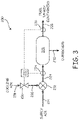
- FIG. 3 is a schematic view of nitrogen generation system 200.
- NGS 200 includes mixer 212, supply air input 214, flow control valve 216, cooling air input 218, cooling air line 220, temperature conditioned air line 224, ASM 226, NEA line 228, OEA line 230, controller 232, sensor 234, and sensor 236.
- Mixer 212 receives supply air through supply air input 214.
- Flow control valve 216 receives cooling air through cooling air input 218. Cooling air flows out of flow control valve 216 and into mixer 212 through cooling air line 220.
- Temperature conditioned air exits mixer 212 through temperature conditioned air line 224.
- ASM 226 receives temperature conditioned air through temperature conditioned air line 224.
- ASM 226 produces NEA and OEA. NEA exits ASM 226 through NEA line 228, and OEA exits ASM 226 through OEA line 230.
- Controller 232 is connected to flow control valve 216, sensor 234, and sensor 236.
- Sensor 234 measures parameters of the temperature conditioned air in temperature conditioned air line 224.
- Sensor 236 measures parameters of NEA in NEA line 228.
- NGS 200 functions similarly to NGS 10 in FIG. 1 , except NGS 200 includes mixer 212 instead of heat exchanger 12.
- Supply air such as bleed air, flows through supply air input 214 and into mixer 212.
- the supply air entering mixer 212 is between about 30 psi and about 40 psi.
- Cooling air also flows into mixer 212 through cooling air line 220.
- the cooling air flows into flow control valve 216 through cooling air input 218.
- Flow control valve 216 controls the flow of cooling air through cooling air line 220 and into mixer 212.
- the cooling air entering mixer 212 is between about 30 psi and about 40 psi.
- Mixer 212 mixes the supply air and cooling air in order to produce temperature conditioned air. Temperature conditioned air exits mixer 212 through temperature conditioned air line 224. Flow control valve 216 controls the flow of cooling air into mixer 212 in order to control the temperature of the temperature conditioned air exiting mixer 212 and entering ASM 226. The temperature conditioned air flows through temperature conditioned air line 224 and into ASM 226. Sensor 234 measures parameters such as temperature, flow rate, and oxygen concentration of the temperature conditioned air in temperature conditioned air line 224. ASM 226 separates the temperature conditioned air to generate NEA and OEA. NEA exits ASM 226 through NEA line 228 and is distributed to fuel tanks and other containers in the aircraft that require inerting. Sensor 236 measures parameters such as temperature, flow rate, and oxygen concentration of the NEA in NEA line 228. OEA exits ASM 226 through OEA line 230 and is dumped overboard.
- NGS 210 controls the flow rate and oxygen concentration of the NEA in NEA line 228 with controller 232.
- Controller 232 is connected to flow control valve 216, sensor 234, and sensor 236.
- Controller 232 controls the flow of the cooling air into mixer 212 based on the value of the parameters measured by sensor 236 in the same manner that controller 32 in FIG. 1 controls the flow of cooling air into heat exchanger 12.
Landscapes
- Chemical & Material Sciences (AREA)
- Engineering & Computer Science (AREA)
- Analytical Chemistry (AREA)
- General Chemical & Material Sciences (AREA)
- Oil, Petroleum & Natural Gas (AREA)
- Chemical Kinetics & Catalysis (AREA)
- Aviation & Aerospace Engineering (AREA)
- Separation Using Semi-Permeable Membranes (AREA)
Claims (7)
- Stickstofferzeugungssystem (10, 100, 200), das Folgendes umfasst:einen Wärmetauscher (12, 112, 212) zum Aufnehmen von Zuluft undKühlluft und Bereitstellen von temperaturkonditionierter Zuluft;ein erstes Strömungssteuerventil (16, 116, 216) zum Steuern einer Strömung der Kühlluft durch den Wärmetauscher (12, 112, 212) ;ein Lufttrennmodul (26, 126, 226) zum Aufnehmen von temperaturkonditionierter Zuluft und Erzeugen von mit Stickstoff angereicherter Luft, wobei das Lufttrennmodul (26, 126, 226) eine Membran umfasst;einen ersten Sensor (36, 136, 236) zum Messen eines Parameters der mit Stickstoff angereicherten Luft, ausgewählt aus der Gruppe bestehend aus Temperatur, Strömungsrate, Sauerstoffkonzentration und Kombinationen daraus;eine Ummantelung (127), die das Lufttrennmodul (26, 126, 226) umgibt;ein zweites Strömungssteuerventil (121), das mit der Steuerung (32, 132, 232) verbunden ist, wobei das zweite Strömungssteuerventil ein Dreiwegeventil zum Steuern einer ersten Strömung der temperaturkonditionierten Zuluft in das Lufttrennmodul und zum Steuern einer zweiten Strömung der temperaturkonditionierten Zuluft in die Ummantelung ist; und eine Steuerung (32, 132, 232), die mit dem ersten Sensor und dem ersten Strömungssteuerventil zum Steuern der Strömung der Kühlluft durch den Wärmetauscher auf Grundlage des Parameters der mit Stickstoff angereicherten Luft, der durch den ersten Sensor gemessen wird, verbunden ist, und dadurch gekennzeichnet, dass die Steuerung dazu konfiguriert ist, Durchlässigkeit und Selektivität des Lufttrennmoduls gemäß einer Flugphase eines Flugzeugs durch Steuern der Temperatur der Membran des Lufttrennmoduls (26, 126, 226) zu manipulieren, wodurch wiederum die Strömungsrate und der Sauerstoffgehalt der mit Stickstoff angereicherten Luft gesteuert wird, wobei die Steuerung (32, 132, 232) ferner mit dem zweiten Strömungssteuerventil (121) zum Steuern einer ersten Strömung der temperaturkonditionierten Zuluft in das Lufttrennmodul und zum Steuern einer zweiten Strömung der temperaturkonditionierten Zuluft in die Ummantelung auf Grundlage des gemessenen Parameters der mit Stickstoff angereicherten Luft verbunden ist.
- Stickstofferzeugungssystem nach Anspruch 1, wobei der Wärmetauscher (12, 112, 212) ein Plattenwärmetauscher oder ein Mantel- und Rohrwärmetauscher ist.
- Stickstofferzeugungssystem nach Anspruch 1 oder 2, wobei die Zuluft Zapfluft ist und die Kühlluft Stauluft ist.
- Stickstofferzeugungssystem nach einem der vorstehenden Ansprüche, wobei die Membran aus einem Polymer gefertigt ist, das aus der Gruppe bestehend aus poly(1-Timethylsilyl-1-Propin), Teflon, Silikongummi, poly(4-Methyl-1-Penten), poly(Phenylenoxid), Ethylzellulose, Polyimid, Polysulfon, Polyaramid, Tetrabrom-bis-Polycarbonat und Kombinationen daraus ausgewählt ist.
- Stickstofferzeugungssystem nach einem der vorstehenden Ansprüche und ferner umfassend einen zweiten Sensor (34, 134, 234) zum Messen eines Parameters der temperaturkonditionierten Zuluft, ausgewählt aus der Gruppe bestehend aus Temperatur, Strömungsrate, Sauerstoffkonzentration und Kombinationen daraus, wobei der zweite Sensor mit der Steuerung (32, 132, 232) verbunden ist.
- Verfahren zum Erzeugen von mit Stickstoff angereicherter Luft, wobei das Verfahren Folgendes umfasst:Kühlen von Zuluft mit Kühlluft, um temperaturkonditionierte Zuluft durch Strömen der Zuluft durch einen Wärmetauscher (12, 112, 212) zu produzieren; undStrömen der Strömung der Kühlluft durch den Wärmetauscher (12, 112, 212);Strömen einer ersten Strömung der temperaturkonditionierten Zuluft durch ein Lufttrennmodul (26, 126, 226), um mit Stickstoff angereicherte Luft zu erzeugen;Strömen einer zweiten Strömung von temperaturkonditionierter Zuluft durch eine Ummantelung, die das Lufttrennmodul (26, 126, 226) umgibt;Messen eines Parameters der mit Stickstoff angereicherten Luft, ausgewählt aus der Gruppe bestehend aus Temperatur, Strömungsrate, Sauerstoffkonzentration und Kombinationen daraus;Steuern einer Strömung der Kühlluft auf Grundlage des gemessenen Parameters der mit Stickstoff angereicherten Luft, und gekennzeichnet durch Manipulieren der Durchlässigkeit und Selektivität des Lufttrennmoduls gemäß einer Flugphase eines Flugzeugs und ferner umfassend Steuern der ersten Strömung der temperaturkonditionierten Zuluft durch das Lufttrennmodul (26, 126, 226) und Steuern der zweiten Strömung der temperaturkonditionierten Zuluft durch die Ummantelung auf Grundlage des gemessenen Parameters der mit Stickstoff angereicherten Luft.
- Verfahren nach Anspruch 6, wobei die Temperatur der Zuluft zwischen 148 Grad Celsius und 233 Grad Celsius liegt, wobei die Temperatur der Kühlluft zwischen -46 Grad Celsius und 43,4 Grad Celsius liegt und wobei die Temperatur der mit Stickstoff angereicherten Luft zwischen 15 Grad Celsius und 93,4 Grad Celsius liegt.
Applications Claiming Priority (1)
| Application Number | Priority Date | Filing Date | Title |
|---|---|---|---|
| US14/736,819 US10137406B2 (en) | 2015-06-11 | 2015-06-11 | Temperature controlled nitrogen generation system |
Publications (2)
| Publication Number | Publication Date |
|---|---|
| EP3103544A1 EP3103544A1 (de) | 2016-12-14 |
| EP3103544B1 true EP3103544B1 (de) | 2022-05-11 |
Family
ID=56148142
Family Applications (1)
| Application Number | Title | Priority Date | Filing Date |
|---|---|---|---|
| EP16174189.7A Active EP3103544B1 (de) | 2015-06-11 | 2016-06-13 | Temperaturgesteuertes stickstofferzeugungssystem und verfahren zur erzeugung von mit stickstoff angereicherter luft |
Country Status (2)
| Country | Link |
|---|---|
| US (5) | US10137406B2 (de) |
| EP (1) | EP3103544B1 (de) |
Families Citing this family (15)
| Publication number | Priority date | Publication date | Assignee | Title |
|---|---|---|---|---|
| KR101676099B1 (ko) * | 2014-09-24 | 2016-11-15 | 오씨아이 주식회사 | Nf3 가스 분리농축 방법, 장치 및 시스템 |
| US9694314B2 (en) * | 2014-10-15 | 2017-07-04 | Parker-Hannifin Corporation | OBIGGS ASM performance modulation via temperature control |
| US10137406B2 (en) | 2015-06-11 | 2018-11-27 | Hamilton Sundstrand Corporation | Temperature controlled nitrogen generation system |
| US10786778B2 (en) * | 2016-01-15 | 2020-09-29 | System Instruments Co., Ltd. | Power supply control device of nitrogen gas generator |
| US10312536B2 (en) | 2016-05-10 | 2019-06-04 | Hamilton Sundstrand Corporation | On-board aircraft electrochemical system |
| US10300431B2 (en) | 2016-05-31 | 2019-05-28 | Hamilton Sundstrant Corporation | On-board vehicle inert gas generation system |
| US10307708B2 (en) | 2016-06-24 | 2019-06-04 | Hamilton Sundstrand Corporation | Fuel tank system and method |
| FR3054795B1 (fr) * | 2016-08-03 | 2018-07-20 | Zodiac Aerotechnics | Procede et systeme d'inertage d'un reservoir de carburant |
| US10427800B2 (en) | 2016-10-31 | 2019-10-01 | Hamilton Sundstrand Corporation | Air separation system for fuel stabilization |
| US10150571B2 (en) * | 2016-11-10 | 2018-12-11 | Hamilton Sundstrand Corporation | On-board aircraft reactive inerting dried gas system |
| DE112017007039T5 (de) * | 2017-02-10 | 2019-10-31 | Asahi Kasei Kabushiki Kaisha | Hohlfasermembranmodul und Filtrationsverfahren |
| FR3098795B1 (fr) * | 2019-07-18 | 2021-10-15 | Dassault Aviat | Systeme d'inertage et aeronef et methode d'inertage associes |
| EP3960636B1 (de) * | 2020-08-28 | 2025-01-08 | The Boeing Company | System und verfahren zur verwaltung von lufttrennmodulen |
| CN111994289A (zh) * | 2020-09-02 | 2020-11-27 | 重庆交通大学 | 一种飞机燃油箱惰化系统及惰化方法 |
| CN112370947B (zh) * | 2020-11-17 | 2022-07-12 | 宁波顺泽橡胶有限公司 | 一种节能环保型丁腈橡胶改造废气废热回收利用装置 |
Family Cites Families (70)
| Publication number | Priority date | Publication date | Assignee | Title |
|---|---|---|---|---|
| US1976336A (en) * | 1932-06-20 | 1934-10-09 | Carbo Oxygen Company | Apparatus for producing oxygen from liquid air |
| US2545462A (en) * | 1948-03-17 | 1951-03-20 | Koppers Co Inc | System for separation of argon from air |
| NL281806A (de) * | 1955-11-10 | 1900-01-01 | ||
| US2908144A (en) * | 1956-01-04 | 1959-10-13 | Union Carbide Corp | Process and apparatus for separating gas mixtures |
| US2926501A (en) * | 1956-12-24 | 1960-03-01 | Union Stock Yard & Transit Co Chicago | Method of and apparatus for recovering nitrogen from air by use of a cold boiling liquid such as nitrogen |
| US3563047A (en) * | 1967-08-04 | 1971-02-16 | Mc Donnell Douglas Corp | Production of high purity oxygen from air |
| US3467349A (en) * | 1967-11-09 | 1969-09-16 | Robert A Gautier | System and method for freeing aircraft fuels of moisture,micro-organisms and other contaminants |
| US3590559A (en) * | 1968-03-06 | 1971-07-06 | Parker Hannifin Corp | Fuel tank inerting system |
| DE2314301C3 (de) * | 1973-03-22 | 1978-07-20 | Bayerische Motoren Werke Ag, 8000 Muenchen | Unilaufkiihlvorrichtung für Kolbenbrennkraftmaschinen |
| DE2504659C3 (de) * | 1975-02-05 | 1988-02-11 | Hüls AG, 4370 Marl | Verfahren zum geregelten Abführen der Reaktionswärme bei Polymerisationsreaktionen in Dispersion bzw. Lösung |
| JPS53140417A (en) * | 1977-05-12 | 1978-12-07 | Toyota Central Res & Dev Lab Inc | Fuel feed system employing hollow cylindrical ultrasonic vibrator |
| SU939551A1 (ru) * | 1978-12-25 | 1982-06-30 | Институт Биохимии И Физиологии Микроорганизмов Ан Ссср | Устройство дл автоматической стабилизации процесса термообработки жидких сред |
| JPS5925107B2 (ja) * | 1979-08-31 | 1984-06-14 | マツダ株式会社 | エンジンの排気ガス浄化装置 |
| JPS56148610A (en) * | 1980-04-18 | 1981-11-18 | Toyota Motor Corp | Cooling device for engine |
| JPS56165713A (en) * | 1980-05-21 | 1981-12-19 | Toyota Motor Corp | Cooler for engine |
| US4338959A (en) * | 1980-10-29 | 1982-07-13 | Borg-Warner Corporation | Device to automatically add a controlled amount of corrosion inhibitor in an engine cooling system |
| DK150665C (da) * | 1985-04-11 | 1987-11-30 | Einar Dyhr | Drosselventil til regujlering af gennemstroemning og dermed bagtryk i |
| US5271846A (en) * | 1986-12-25 | 1993-12-21 | Lignyte Co., Ltd. | Method for separating a liquid component from a solution containing two or more liquid components |
| DE3821631A1 (de) * | 1987-07-28 | 1989-02-09 | Bader Paul | Verschluss fuer eine maennliche harnroehre |
| JP3375645B2 (ja) * | 1991-05-14 | 2003-02-10 | 株式会社日立製作所 | 内燃機関の制御装置 |
| US5294345A (en) * | 1993-02-01 | 1994-03-15 | Membrane Technology And Research, Inc. | Membrane module assembly |
| US5823713A (en) * | 1994-01-03 | 1998-10-20 | Biran; Daniel | Scuba diving apparatus with depth control |
| US5624374A (en) * | 1994-11-03 | 1997-04-29 | Von Iderstein; Irwin F. | Involuntary urine control apparatus, system and method |
| TW354259B (en) * | 1994-11-03 | 1999-03-11 | Uroscientific Inc | Urethra control system the invention relates to an involunary urine control system |
| JP3501899B2 (ja) * | 1996-04-15 | 2004-03-02 | ヤマハ発動機株式会社 | 船舶推進機用排気装置 |
| US6125638A (en) * | 1998-08-21 | 2000-10-03 | The Boc Group, Inc. | Optical fiber cooling process |
| US6491739B1 (en) | 1999-11-09 | 2002-12-10 | Litton Systems, Inc. | Air separation module using a fast start valve for fast warm up of a permeable membrane air separation module |
| US6691702B2 (en) * | 2000-08-03 | 2004-02-17 | Sequal Technologies, Inc. | Portable oxygen concentration system and method of using the same |
| JP2005522629A (ja) * | 2002-04-11 | 2005-07-28 | エイ. ハーゼ,リチャード | 水燃焼技術−水素と酸素を燃焼させる方法、プロセス、システム及び装置 |
| US6997970B2 (en) * | 2002-06-25 | 2006-02-14 | Carleton Life Support Systems, Inc. | Oxygen/inert gas generator |
| US6729359B2 (en) | 2002-06-28 | 2004-05-04 | Shaw Aero Devices, Inc. | Modular on-board inert gas generating system |
| US6739359B2 (en) | 2002-10-04 | 2004-05-25 | Shaw Aero Devices, Inc. | On-board inert gas generating system optimization by pressure scheduling |
| AT413978B (de) * | 2003-01-20 | 2006-07-15 | Bamed Ag | Luftventil für einen deckel eines trinkbehälters |
| AT413979B (de) * | 2003-01-20 | 2006-07-15 | Bamed Ag | Trink-mundstück |
| US7374601B2 (en) | 2003-09-22 | 2008-05-20 | Parker-Hannifin Corporation | Air separation system and method with modulated warning flow |
| US7081153B2 (en) | 2003-12-02 | 2006-07-25 | Honeywell International Inc. | Gas generating system and method for inerting aircraft fuel tanks |
| US7204868B2 (en) | 2004-03-30 | 2007-04-17 | The Boeing Company | Method and apparatus for generating an inert gas on a vehicle |
| US7306646B2 (en) | 2004-04-08 | 2007-12-11 | Parker-Hannifin Corporation | Utilization of compressor surge control air in an aircraft on-board inert gas generating system |
| US7274601B2 (en) | 2004-09-27 | 2007-09-25 | Macronix International Co., Ltd. | Programming and erasing method for charge-trapping memory devices |
| US7509968B2 (en) * | 2004-07-28 | 2009-03-31 | Hamilton Sundstrand Corporation | Flow control for on-board inert gas generation system |
| DE102005045760B4 (de) * | 2005-09-23 | 2008-12-24 | Hoffmann Consorten Hamburg Gmbh | Verfahren und Vorrichtung zur Herstellung einer konditionierten Atmosphäre |
| WO2007067654A2 (en) * | 2005-12-07 | 2007-06-14 | Lightstream Technologies | Method and apparatus for cooling high power flash lamps |
| US7625434B2 (en) | 2006-09-12 | 2009-12-01 | Honeywell International Inc. | Enhanced OBIGGS |
| MY154251A (en) * | 2007-11-12 | 2015-05-29 | Exxonmobil Upstream Res Co | Methods of generating and utility gas |
| MX2010010257A (es) * | 2008-03-19 | 2011-09-28 | Vale Solucoees Em En S A | Generador de vapor viciado. |
| US20100018218A1 (en) * | 2008-07-25 | 2010-01-28 | Riley Horace E | Power plant with emissions recovery |
| US7918358B2 (en) * | 2008-10-30 | 2011-04-05 | The Boeing Company | System and method to make a fuel tank inert |
| US20100155046A1 (en) * | 2008-12-18 | 2010-06-24 | Eric Surawski | Temperature control system for an on board inert gas generation systems |
| CN102271943A (zh) * | 2009-01-09 | 2011-12-07 | 卡森尼可关精株式会社 | 车辆用空调装置 |
| US8016124B2 (en) * | 2009-04-22 | 2011-09-13 | Honeywell International Inc. | Thin film gas separation membranes |
| US8444749B2 (en) * | 2009-06-10 | 2013-05-21 | L'air Liquide, Societe Anonyme Pour L'etude Et L'exploitation Des Procedes Georges Claude | Method and system for membrane-based gas recovery |
| US8668752B2 (en) * | 2009-09-04 | 2014-03-11 | Rolls-Royce Fuel Cell Systems (Us) Inc. | Apparatus for generating a gas which may be used for startup and shutdown of a fuel cell |
| FR2976059B1 (fr) * | 2011-05-31 | 2013-05-31 | Air Liquide | Appareil et procede integre de separation d'un melange de dioxyde de carbone et au moins un autre gaz et de separation d'air par distillation cryogenique |
| US8840705B2 (en) * | 2011-07-07 | 2014-09-23 | Linde Aktiengesellschaft | Methods for the ozonolysis of organic compounds |
| AU2012312423A1 (en) * | 2011-09-21 | 2014-04-03 | Dow Global Technologies Llc | Azide crosslinked and physically crosslinked polymers for membrane separation |
| US8801831B1 (en) * | 2011-12-13 | 2014-08-12 | The Boeing Company | Fuel saving inert gas generation system |
| US9327243B2 (en) * | 2012-08-24 | 2016-05-03 | The Boeing Company | Aircraft fuel tank flammability reduction methods and systems |
| US9187324B2 (en) * | 2012-08-30 | 2015-11-17 | Element 1 Corp. | Hydrogen generation assemblies and hydrogen purification devices |
| JP5998071B2 (ja) * | 2013-01-31 | 2016-09-28 | 住友化学株式会社 | 連続重合装置、重合体組成物の製造方法およびインジェクションバルブ |
| CN104937358B (zh) * | 2013-02-25 | 2017-05-10 | 三菱重工压缩机有限公司 | 二氧化碳液化装置 |
| JP5655104B2 (ja) * | 2013-02-26 | 2015-01-14 | 大陽日酸株式会社 | 空気分離方法及び空気分離装置 |
| US9494064B2 (en) * | 2013-08-01 | 2016-11-15 | Elwha Llc | Systems, methods, and apparatuses related to vehicles with reduced emissions |
| US20160051806A1 (en) * | 2013-08-27 | 2016-02-25 | David S. Goldsmith | Ductus side-entry jackets and prosthetic disorder response systems |
| US10465302B2 (en) * | 2014-08-07 | 2019-11-05 | Marathon Systems, Inc. | Modular gaseous electrolysis apparatus with actively-cooled header module, co-disposed heat exchanger module and gas manifold modules therefor |
| US9623982B2 (en) * | 2015-01-08 | 2017-04-18 | Airbus Group India Private Limited | On-board aircraft nitrogen enriched air and cooling fluid generation system and method |
| US9903323B2 (en) * | 2015-03-10 | 2018-02-27 | Denso International America, Inc. | Emissions reduction system for an internal combustion engine |
| US9676629B2 (en) * | 2015-06-09 | 2017-06-13 | Praxair Technology, Inc. | Helium enhanced heat transfer in adsorptive liquid or gas phase argon purification processes |
| US10137406B2 (en) * | 2015-06-11 | 2018-11-27 | Hamilton Sundstrand Corporation | Temperature controlled nitrogen generation system |
| US10118129B2 (en) * | 2017-03-31 | 2018-11-06 | Mitsubishi Heavy Industries, Ltd. | Natural-gas purification apparatus |
| US11236021B2 (en) * | 2017-12-22 | 2022-02-01 | Goodrich Corporation | Mitigating pyrophoric deposits in exhaust piping during SIC CVI/CVD processes by introducing water vapor into an outlet portion of a reaction chamber |
-
2015
- 2015-06-11 US US14/736,819 patent/US10137406B2/en active Active
-
2016
- 2016-06-13 EP EP16174189.7A patent/EP3103544B1/de active Active
-
2018
- 2018-10-25 US US16/170,681 patent/US20190060827A1/en not_active Abandoned
- 2018-10-30 US US16/175,293 patent/US10434465B2/en active Active
-
2019
- 2019-07-05 US US16/503,873 patent/US10493401B2/en active Active
-
2020
- 2020-01-13 US US16/740,994 patent/US11117094B2/en active Active
Also Published As
| Publication number | Publication date |
|---|---|
| US20190060827A1 (en) | 2019-02-28 |
| US20160361684A1 (en) | 2016-12-15 |
| US10434465B2 (en) | 2019-10-08 |
| US20200171428A1 (en) | 2020-06-04 |
| US11117094B2 (en) | 2021-09-14 |
| EP3103544A1 (de) | 2016-12-14 |
| US10493401B2 (en) | 2019-12-03 |
| US10137406B2 (en) | 2018-11-27 |
| US20190060828A1 (en) | 2019-02-28 |
| US20190329177A1 (en) | 2019-10-31 |
Similar Documents
| Publication | Publication Date | Title |
|---|---|---|
| US10493401B2 (en) | Temperature controlled nitrogen generation system | |
| US7374601B2 (en) | Air separation system and method with modulated warning flow | |
| US7608131B2 (en) | Three flow architecture and method for aircraft OBIGGS | |
| JP5275302B2 (ja) | 燃料タンク内のアレッジの生成方法および装置 | |
| US6997970B2 (en) | Oxygen/inert gas generator | |
| US10329027B2 (en) | Fuel deoxygenation systems | |
| EP2772436B1 (de) | Flugzeuginertisierungssystem | |
| EP1108458B1 (de) | Lufttrennvorrichtung mit Schnellstartventil zum schnellen Aufwärmen der permeablen Membran | |
| EP3117873B1 (de) | Sauerstoffmessung für kraftstofftankinertisierungssystem | |
| US20110263035A1 (en) | Determining oxygen concentration in ullage using catalytic oxidation | |
| EP3441128B1 (de) | Inertgaserzeugungssystem und -methode | |
| US9039818B2 (en) | Method for processing air | |
| US9272790B2 (en) | Nitrogen enriched air supply system and aircraft | |
| EP3159265A1 (de) | Flugzeug mit einem flugzeugluftzuführsystem zur reduzierung einer effektiven höhe eines flugzeugcockpits | |
| US9963239B2 (en) | Nitrogen enriched air supply system and aircraft | |
| US10105639B2 (en) | Inert gas generation system, and an aircraft fuel tank inerting system implementing said inert gas generation system | |
| EP3501992B1 (de) | Kraftstofftankinertisierungssystem | |
| Burns et al. | Flight-testing of the FAA onboard inert gas generation system on an Airbus A320 | |
| BR102017015801A2 (pt) | Método para controle de um sistema de inertização, e, sistema de inertização. | |
| EP3117888B1 (de) | Lufttrennungssystem für ein luftfahrzeug mit sauerstoffsensorschutz | |
| EP3315412B1 (de) | Lufttrennungssystem zur kraftstoffstabilisierung | |
| EP4321222B1 (de) | Halon-alternativen zur flugzeugbrandunterdrückung |
Legal Events
| Date | Code | Title | Description |
|---|---|---|---|
| PUAI | Public reference made under article 153(3) epc to a published international application that has entered the european phase |
Free format text: ORIGINAL CODE: 0009012 |
|
| STAA | Information on the status of an ep patent application or granted ep patent |
Free format text: STATUS: THE APPLICATION HAS BEEN PUBLISHED |
|
| AK | Designated contracting states |
Kind code of ref document: A1 Designated state(s): AL AT BE BG CH CY CZ DE DK EE ES FI FR GB GR HR HU IE IS IT LI LT LU LV MC MK MT NL NO PL PT RO RS SE SI SK SM TR |
|
| AX | Request for extension of the european patent |
Extension state: BA ME |
|
| STAA | Information on the status of an ep patent application or granted ep patent |
Free format text: STATUS: REQUEST FOR EXAMINATION WAS MADE |
|
| 17P | Request for examination filed |
Effective date: 20170614 |
|
| RBV | Designated contracting states (corrected) |
Designated state(s): AL AT BE BG CH CY CZ DE DK EE ES FI FR GB GR HR HU IE IS IT LI LT LU LV MC MK MT NL NO PL PT RO RS SE SI SK SM TR |
|
| STAA | Information on the status of an ep patent application or granted ep patent |
Free format text: STATUS: EXAMINATION IS IN PROGRESS |
|
| 17Q | First examination report despatched |
Effective date: 20191017 |
|
| GRAP | Despatch of communication of intention to grant a patent |
Free format text: ORIGINAL CODE: EPIDOSNIGR1 |
|
| STAA | Information on the status of an ep patent application or granted ep patent |
Free format text: STATUS: GRANT OF PATENT IS INTENDED |
|
| GRAS | Grant fee paid |
Free format text: ORIGINAL CODE: EPIDOSNIGR3 |
|
| INTG | Intention to grant announced |
Effective date: 20220314 |
|
| GRAA | (expected) grant |
Free format text: ORIGINAL CODE: 0009210 |
|
| STAA | Information on the status of an ep patent application or granted ep patent |
Free format text: STATUS: THE PATENT HAS BEEN GRANTED |
|
| RAP3 | Party data changed (applicant data changed or rights of an application transferred) |
Owner name: HAMILTON SUNDSTRAND CORPORATION |
|
| AK | Designated contracting states |
Kind code of ref document: B1 Designated state(s): AL AT BE BG CH CY CZ DE DK EE ES FI FR GB GR HR HU IE IS IT LI LT LU LV MC MK MT NL NO PL PT RO RS SE SI SK SM TR |
|
| REG | Reference to a national code |
Ref country code: GB Ref legal event code: FG4D |
|
| REG | Reference to a national code |
Ref country code: CH Ref legal event code: EP |
|
| REG | Reference to a national code |
Ref country code: AT Ref legal event code: REF Ref document number: 1490902 Country of ref document: AT Kind code of ref document: T Effective date: 20220515 |
|
| REG | Reference to a national code |
Ref country code: DE Ref legal event code: R096 Ref document number: 602016071970 Country of ref document: DE |
|
| REG | Reference to a national code |
Ref country code: IE Ref legal event code: FG4D |
|
| REG | Reference to a national code |
Ref country code: LT Ref legal event code: MG9D |
|
| REG | Reference to a national code |
Ref country code: NL Ref legal event code: MP Effective date: 20220511 |
|
| REG | Reference to a national code |
Ref country code: AT Ref legal event code: MK05 Ref document number: 1490902 Country of ref document: AT Kind code of ref document: T Effective date: 20220511 |
|
| PG25 | Lapsed in a contracting state [announced via postgrant information from national office to epo] |
Ref country code: SE Free format text: LAPSE BECAUSE OF FAILURE TO SUBMIT A TRANSLATION OF THE DESCRIPTION OR TO PAY THE FEE WITHIN THE PRESCRIBED TIME-LIMIT Effective date: 20220511 Ref country code: PT Free format text: LAPSE BECAUSE OF FAILURE TO SUBMIT A TRANSLATION OF THE DESCRIPTION OR TO PAY THE FEE WITHIN THE PRESCRIBED TIME-LIMIT Effective date: 20220912 Ref country code: NO Free format text: LAPSE BECAUSE OF FAILURE TO SUBMIT A TRANSLATION OF THE DESCRIPTION OR TO PAY THE FEE WITHIN THE PRESCRIBED TIME-LIMIT Effective date: 20220811 Ref country code: NL Free format text: LAPSE BECAUSE OF FAILURE TO SUBMIT A TRANSLATION OF THE DESCRIPTION OR TO PAY THE FEE WITHIN THE PRESCRIBED TIME-LIMIT Effective date: 20220511 Ref country code: LT Free format text: LAPSE BECAUSE OF FAILURE TO SUBMIT A TRANSLATION OF THE DESCRIPTION OR TO PAY THE FEE WITHIN THE PRESCRIBED TIME-LIMIT Effective date: 20220511 Ref country code: HR Free format text: LAPSE BECAUSE OF FAILURE TO SUBMIT A TRANSLATION OF THE DESCRIPTION OR TO PAY THE FEE WITHIN THE PRESCRIBED TIME-LIMIT Effective date: 20220511 Ref country code: GR Free format text: LAPSE BECAUSE OF FAILURE TO SUBMIT A TRANSLATION OF THE DESCRIPTION OR TO PAY THE FEE WITHIN THE PRESCRIBED TIME-LIMIT Effective date: 20220812 Ref country code: FI Free format text: LAPSE BECAUSE OF FAILURE TO SUBMIT A TRANSLATION OF THE DESCRIPTION OR TO PAY THE FEE WITHIN THE PRESCRIBED TIME-LIMIT Effective date: 20220511 Ref country code: ES Free format text: LAPSE BECAUSE OF FAILURE TO SUBMIT A TRANSLATION OF THE DESCRIPTION OR TO PAY THE FEE WITHIN THE PRESCRIBED TIME-LIMIT Effective date: 20220511 Ref country code: BG Free format text: LAPSE BECAUSE OF FAILURE TO SUBMIT A TRANSLATION OF THE DESCRIPTION OR TO PAY THE FEE WITHIN THE PRESCRIBED TIME-LIMIT Effective date: 20220811 Ref country code: AT Free format text: LAPSE BECAUSE OF FAILURE TO SUBMIT A TRANSLATION OF THE DESCRIPTION OR TO PAY THE FEE WITHIN THE PRESCRIBED TIME-LIMIT Effective date: 20220511 |
|
| PG25 | Lapsed in a contracting state [announced via postgrant information from national office to epo] |
Ref country code: RS Free format text: LAPSE BECAUSE OF FAILURE TO SUBMIT A TRANSLATION OF THE DESCRIPTION OR TO PAY THE FEE WITHIN THE PRESCRIBED TIME-LIMIT Effective date: 20220511 Ref country code: PL Free format text: LAPSE BECAUSE OF FAILURE TO SUBMIT A TRANSLATION OF THE DESCRIPTION OR TO PAY THE FEE WITHIN THE PRESCRIBED TIME-LIMIT Effective date: 20220511 Ref country code: LV Free format text: LAPSE BECAUSE OF FAILURE TO SUBMIT A TRANSLATION OF THE DESCRIPTION OR TO PAY THE FEE WITHIN THE PRESCRIBED TIME-LIMIT Effective date: 20220511 Ref country code: IS Free format text: LAPSE BECAUSE OF FAILURE TO SUBMIT A TRANSLATION OF THE DESCRIPTION OR TO PAY THE FEE WITHIN THE PRESCRIBED TIME-LIMIT Effective date: 20220911 |
|
| REG | Reference to a national code |
Ref country code: DE Ref legal event code: R119 Ref document number: 602016071970 Country of ref document: DE |
|
| PG25 | Lapsed in a contracting state [announced via postgrant information from national office to epo] |
Ref country code: SM Free format text: LAPSE BECAUSE OF FAILURE TO SUBMIT A TRANSLATION OF THE DESCRIPTION OR TO PAY THE FEE WITHIN THE PRESCRIBED TIME-LIMIT Effective date: 20220511 Ref country code: SK Free format text: LAPSE BECAUSE OF FAILURE TO SUBMIT A TRANSLATION OF THE DESCRIPTION OR TO PAY THE FEE WITHIN THE PRESCRIBED TIME-LIMIT Effective date: 20220511 Ref country code: RO Free format text: LAPSE BECAUSE OF FAILURE TO SUBMIT A TRANSLATION OF THE DESCRIPTION OR TO PAY THE FEE WITHIN THE PRESCRIBED TIME-LIMIT Effective date: 20220511 Ref country code: EE Free format text: LAPSE BECAUSE OF FAILURE TO SUBMIT A TRANSLATION OF THE DESCRIPTION OR TO PAY THE FEE WITHIN THE PRESCRIBED TIME-LIMIT Effective date: 20220511 Ref country code: DK Free format text: LAPSE BECAUSE OF FAILURE TO SUBMIT A TRANSLATION OF THE DESCRIPTION OR TO PAY THE FEE WITHIN THE PRESCRIBED TIME-LIMIT Effective date: 20220511 Ref country code: CZ Free format text: LAPSE BECAUSE OF FAILURE TO SUBMIT A TRANSLATION OF THE DESCRIPTION OR TO PAY THE FEE WITHIN THE PRESCRIBED TIME-LIMIT Effective date: 20220511 |
|
| REG | Reference to a national code |
Ref country code: CH Ref legal event code: PL |
|
| REG | Reference to a national code |
Ref country code: BE Ref legal event code: MM Effective date: 20220630 |
|
| PG25 | Lapsed in a contracting state [announced via postgrant information from national office to epo] |
Ref country code: MC Free format text: LAPSE BECAUSE OF FAILURE TO SUBMIT A TRANSLATION OF THE DESCRIPTION OR TO PAY THE FEE WITHIN THE PRESCRIBED TIME-LIMIT Effective date: 20220511 |
|
| PLBE | No opposition filed within time limit |
Free format text: ORIGINAL CODE: 0009261 |
|
| STAA | Information on the status of an ep patent application or granted ep patent |
Free format text: STATUS: NO OPPOSITION FILED WITHIN TIME LIMIT |
|
| PG25 | Lapsed in a contracting state [announced via postgrant information from national office to epo] |
Ref country code: AL Free format text: LAPSE BECAUSE OF FAILURE TO SUBMIT A TRANSLATION OF THE DESCRIPTION OR TO PAY THE FEE WITHIN THE PRESCRIBED TIME-LIMIT Effective date: 20220511 |
|
| 26N | No opposition filed |
Effective date: 20230214 |
|
| PG25 | Lapsed in a contracting state [announced via postgrant information from national office to epo] |
Ref country code: LU Free format text: LAPSE BECAUSE OF NON-PAYMENT OF DUE FEES Effective date: 20220613 Ref country code: LI Free format text: LAPSE BECAUSE OF NON-PAYMENT OF DUE FEES Effective date: 20220630 Ref country code: IE Free format text: LAPSE BECAUSE OF NON-PAYMENT OF DUE FEES Effective date: 20220613 Ref country code: CH Free format text: LAPSE BECAUSE OF NON-PAYMENT OF DUE FEES Effective date: 20220630 |
|
| PG25 | Lapsed in a contracting state [announced via postgrant information from national office to epo] |
Ref country code: SI Free format text: LAPSE BECAUSE OF FAILURE TO SUBMIT A TRANSLATION OF THE DESCRIPTION OR TO PAY THE FEE WITHIN THE PRESCRIBED TIME-LIMIT Effective date: 20220511 Ref country code: DE Free format text: LAPSE BECAUSE OF NON-PAYMENT OF DUE FEES Effective date: 20230103 Ref country code: BE Free format text: LAPSE BECAUSE OF NON-PAYMENT OF DUE FEES Effective date: 20220630 |
|
| P01 | Opt-out of the competence of the unified patent court (upc) registered |
Effective date: 20230522 |
|
| PG25 | Lapsed in a contracting state [announced via postgrant information from national office to epo] |
Ref country code: IT Free format text: LAPSE BECAUSE OF FAILURE TO SUBMIT A TRANSLATION OF THE DESCRIPTION OR TO PAY THE FEE WITHIN THE PRESCRIBED TIME-LIMIT Effective date: 20220511 |
|
| PG25 | Lapsed in a contracting state [announced via postgrant information from national office to epo] |
Ref country code: HU Free format text: LAPSE BECAUSE OF FAILURE TO SUBMIT A TRANSLATION OF THE DESCRIPTION OR TO PAY THE FEE WITHIN THE PRESCRIBED TIME-LIMIT; INVALID AB INITIO Effective date: 20160613 |
|
| PG25 | Lapsed in a contracting state [announced via postgrant information from national office to epo] |
Ref country code: MK Free format text: LAPSE BECAUSE OF FAILURE TO SUBMIT A TRANSLATION OF THE DESCRIPTION OR TO PAY THE FEE WITHIN THE PRESCRIBED TIME-LIMIT Effective date: 20220511 Ref country code: CY Free format text: LAPSE BECAUSE OF FAILURE TO SUBMIT A TRANSLATION OF THE DESCRIPTION OR TO PAY THE FEE WITHIN THE PRESCRIBED TIME-LIMIT Effective date: 20220511 |
|
| PG25 | Lapsed in a contracting state [announced via postgrant information from national office to epo] |
Ref country code: MT Free format text: LAPSE BECAUSE OF FAILURE TO SUBMIT A TRANSLATION OF THE DESCRIPTION OR TO PAY THE FEE WITHIN THE PRESCRIBED TIME-LIMIT Effective date: 20220511 |
|
| PG25 | Lapsed in a contracting state [announced via postgrant information from national office to epo] |
Ref country code: BG Free format text: LAPSE BECAUSE OF FAILURE TO SUBMIT A TRANSLATION OF THE DESCRIPTION OR TO PAY THE FEE WITHIN THE PRESCRIBED TIME-LIMIT Effective date: 20220511 |
|
| PG25 | Lapsed in a contracting state [announced via postgrant information from national office to epo] |
Ref country code: BG Free format text: LAPSE BECAUSE OF FAILURE TO SUBMIT A TRANSLATION OF THE DESCRIPTION OR TO PAY THE FEE WITHIN THE PRESCRIBED TIME-LIMIT Effective date: 20220511 |
|
| PGFP | Annual fee paid to national office [announced via postgrant information from national office to epo] |
Ref country code: GB Payment date: 20250520 Year of fee payment: 10 |
|
| PGFP | Annual fee paid to national office [announced via postgrant information from national office to epo] |
Ref country code: FR Payment date: 20250520 Year of fee payment: 10 |
|
| PG25 | Lapsed in a contracting state [announced via postgrant information from national office to epo] |
Ref country code: TR Free format text: LAPSE BECAUSE OF FAILURE TO SUBMIT A TRANSLATION OF THE DESCRIPTION OR TO PAY THE FEE WITHIN THE PRESCRIBED TIME-LIMIT Effective date: 20220511 |